EP1559349B1 - Höhenverstellbare Stuhl-Säule - Google Patents
Höhenverstellbare Stuhl-Säule Download PDFInfo
- Publication number
- EP1559349B1 EP1559349B1 EP04029283A EP04029283A EP1559349B1 EP 1559349 B1 EP1559349 B1 EP 1559349B1 EP 04029283 A EP04029283 A EP 04029283A EP 04029283 A EP04029283 A EP 04029283A EP 1559349 B1 EP1559349 B1 EP 1559349B1
- Authority
- EP
- European Patent Office
- Prior art keywords
- housing
- adjustable
- chair column
- column according
- upright tube
- Prior art date
- Legal status (The legal status is an assumption and is not a legal conclusion. Google has not performed a legal analysis and makes no representation as to the accuracy of the status listed.)
- Expired - Lifetime
Links
Images


Classifications
-
- A—HUMAN NECESSITIES
- A47—FURNITURE; DOMESTIC ARTICLES OR APPLIANCES; COFFEE MILLS; SPICE MILLS; SUCTION CLEANERS IN GENERAL
- A47C—CHAIRS; SOFAS; BEDS
- A47C3/00—Chairs characterised by structural features; Chairs or stools with rotatable or vertically-adjustable seats
- A47C3/20—Chairs or stools with vertically-adjustable seats
- A47C3/30—Chairs or stools with vertically-adjustable seats with vertically-acting fluid cylinder
Definitions
- the invention relates to a height-adjustable chair column according to the preamble of claim 1.
- the invention is therefore based on the object, a height-adjustable chair column in such a way that the standpipe and the housing of the Gas spring can take a defined rotational angle position to each other and maintain this.
- claim 5 shows how a particularly simple production of a positive rotation can be achieved.
- claims 7 and 8 give again, as well as the release is reachable in case of overload.
- the claims 9 and 10 show again how a play-free seat in the direction of rotation can be achieved.
- the anti-rotation device can engage only in a very specific predetermined position of the locking element and the locking abutment.
- the chair column shown in the drawing comprises a standpipe 1 and a guided in this by means of a guide bushing 2, in the direction of a common central longitudinal axis 3 displaceable, adjustable gas spring 4.
- the standpipe 1 has at its lower end a holding cone 5 for attachment in a conventional chair pedestal.
- the gas spring 4 has a substantially cylindrical housing 6, which is guided in the guide bush 2. Concentric with the axis 3, an inner tube 7 is arranged in the housing 6, between which and the housing 6, an annular channel 8 is formed. At the located outside of the standpipe 1 upper end of the housing 6, a valve 9 is arranged in this, which is actuated by means of a protruding from the housing 6 actuating pin 10. It is used for selective connection of the annular channel 8 with the valve 9 adjacent, formed in the inner tube 7 first part housing space eleventh
- a piston rod 12 is arranged concentrically to the axis 3 and slidable in the direction thereof, which is at the valve 9 opposite, located in the standpipe 1 lower end of the housing 6 led out of this. It is guided gas-tight in this area by means of a guide-sealing unit 13.
- a piston 14 is attached to this, which is guided sealed on the inner tube 7. It separates the first part housing space 11 from a second part housing space 15 formed between the piston 14 and the guide-seal unit 13.
- a conically tapered fastening section 16 is formed thereon.
- the gas spring 4 on a corresponding receptacle on the underside a chair seat for example, a chair seat support, can be fastened.
- the piston rod 12 is supported via an axial bearing 17 on the bottom 18 of the standpipe 1 and releasably secured there by means of a mounting bracket 19.
- the annular channel 8 and the part-housing chambers 11 and 15 are filled with gas under relatively high pressure and optionally a predetermined amount of oil.
- the second part-housing space 15 is connected to the guide-seal unit 13 by means of an overflow channel 20 is constantly connected to the annular channel 8. If the valve 9 is opened by pressing the actuating pin 10, then with sufficient relief of the housing 6, the piston rod is pushed out, d. H. the housing 6 is pushed out of the standpipe 1 upwards. With a corresponding load on the housing 6, however, the housing 6 is pushed down into the standpipe 1 and thus the piston rod 12 retracted into the housing 6.
- the housing 6 When closing the valve 9 by releasing the actuating pin 10, the housing 6 is as it were locked to the piston rod 12 via the pressure prevailing in the housing 6, wherein a gas filling is an elastically resilient locking and in the presence of a predominant liquid filling to a substantially rigid locking is.
- the entire structure and operation of the gas spring 4 are - so far described - well known, for example, from the basic patent DE 18 12 282 (corresponding to US 3,656,593). Accordingly, the basic structure and operation of the chair column from the patent DE 19 31 021 is known.
- the guide bush 2 has on its outer side longitudinal ribs 21, by means of which it is supported on the inner wall 22 of the standpipe 1 radially to the axis 3. Between the longitudinal ribs 21 are corresponding longitudinal grooves 23 trained. At the located in the interior of the standpipe 1 end of the guide bushing 2, a locking abutment 24 is mounted, which consists essentially of a ring 25 and formed on this, parallel to the axis 3, inserted into the longitudinal grooves 23 retaining webs 26. By means of these retaining webs 26, the abutment 24 is fixedly secured to the guide bush 2, in particular rotationally fixed. It is welded to the likewise made of weldable plastic guide bushing 2 by ultrasonic welding or the like and clamped. The guide bush 2 itself is sufficiently rotationally fixed, optionally by additional securing means, pressed into the standpipe 1.
- a locking element 27 is attached to this, which is also formed substantially in the form of a ring.
- the guide bush 2, the locking abutment 24 and the locking element 27 form a torsion-protection.
- the abutment 24 and the element 27 are each provided with cutouts 28, 29, which in turn locking webs 30, 31 are formed.
- the cutouts 28, 29 and thus the webs 30, 31 are formed so that the locking web 30 of the abutment 24 engages in the cutout 29 of the element 27 and the web 31 of the element 27 in the cutout 28 of the abutment 24, namely play.
- the webs 30, 31 each have inclined surfaces 32, 33 which are arranged obliquely to the axis 3, that the cutouts 28, 29 each extend to its open side.
- the oblique surfaces 32 and 33 which are associated with each other when the element 27 engages in the abutment 24, have the same opening angle a to an axis-parallel line.
- the circumferential extent of the locking webs 30, 31 is dimensioned such that upon penetration of the locking element 27 in the locking abutment 24 between the bottom 34 of the cutout 28 of the abutment 24 and the locking web 31 of the locking element 27 and between the bottom 35 of the cutout 29 of the locking element and the locking web 30 a game 36 or 37 in the direction of the axis 3 remains. In this case, therefore, the inclined surfaces 32, 33 each firmly against each other, ie the locking element 27 has no tangential game, so no rotational play, relative to the abutment 24th
- the opening angle ⁇ is chosen so that, in the case of correspondingly large torques acting between the housing 6 and the standpipe 1, the locking element 27 and the locking abutment 24 are forced apart via the inclined surfaces 32, 33 in the direction of the axis 3.
- the dimensioning is done by a vote of the existing in the extended state between the piston rod 12 and the housing 6 due to the internal gas pressure extension force and the mean radius r of the inclined surfaces 32, 33 and the torque considered admissible.
- the twist-lock thus works form-fitting until reaching the specified torque.
Landscapes
- Chairs Characterized By Structure (AREA)
- Fluid-Damping Devices (AREA)
- Special Chairs (AREA)
- Chair Legs, Seat Parts, And Backrests (AREA)
Description
- Die Erfindung betrifft eine höhenverstellbare Stuhl-Säule nach dem Oberbegriff des Anspruches 1.
- Aus der US 5,944,290 A (entspr. DE 196 28 721 A1) ist eine derartige Stuhlsäule bekannt, die im Bereich ihres kolbenstangenaustrittsseitigen Endes mit drei radial vorspringenden Stegen versehen ist, die in entsprechende Nuten im Standrohr eingreifen. Hierdurch wird sichergestellt, dass sich ein am Gehäuse der Gasfeder befestigter Stuhlsitz oder dergleichen oder eine hieran angebrachte Tischplatte gegenüber dem Standrohr nicht verdrehen kann. Ähnliche Ausgestaltungen sind aus der US 5,531,413 A (entspr. EP 0 622 037 A1) bekannt.
- Aus der DE 19 31 021 C sind in ihrem Grundaufbau gleichartige Stuhl-Säulen bekannt, die eine längenverstellbare Gasfeder aufweisen, deren Gehäuse in einem Standrohr verschiebbar geführt ist. Das Standrohr wird in einem Fußgestell befestigt, während das Gehäuse der Gasfeder im Standrohr geführt ist, und zwar in der Regel in einer im Standrohr angebrachten Führungsbüchse. Wenn hiermit ausgerüstete Stühle eine hochklappbare Sitzfläche aufweisen, dann können mehrere Stühle so weit ineinander geschoben werden, dass die Stuhl-Säulen in einen relativ geringen Abstand zueinander kommen. Dies kann beispielsweise zum platzsparenden Lagern von Stühlen oder auch zum Verschieben einer ganzen Gruppe von Stühlen hilfreich sein. Hierbei ist es wünschenswert, dass die Stühle definierte Positionen zueinander einnehmen und diese beibehalten.
- Der Erfindung liegt daher die Aufgabe zugrunde, eine höhenverstellbare Stuhl-Säule so auszugestalten, dass das Standrohr und das Gehäuse der Gasfeder eine definierte Dreh-Winkel-Stellung zueinander einnehmen können und diese auch beibehalten.
- Diese Aufgabe wird erfindungsgemäß durch die Merkmale im Kennzeichnungsteil des Anspruches 1 gelöst. Durch die erfindungsgemäße Ausgestaltung wird erreicht, dass am Ende des vollständigen Ausfahrens des Gehäuses der Gasfeder aus dem Standrohr das Gehäuse und das Standrohr gegeneinander zumindest weitgehend unverdrehbar festgelegt werden. Sie nehmen also eine feste Drehstellung zueinander ein. Diese Feststellung kann durch Kraftschluss erfolgen; der Formschluss nach Anspruch 2 ist aber besonders vorteilhaft, weil zuverlässiger. Auch eine formschlüssige Verbindung kann so ausgelegt werden, dass sie sich nach Anspruch 3 bei Überschreiten eines vorgegebenen Drehmomentes löst. Eine vorteilhafte Ausgestaltung gibt hierzu Anspruch 4 wieder.
- Eine besonders einfache Ausgestaltung ist Anspruch 5 zu entnehmen, wobei Anspruch 6 wiedergibt, wie ein besonders einfaches Herstellen einer formschlüssigen Verdrehsicherung erreichbar ist. Die Ansprüche 7 und 8 geben wieder, wie auch das Lösen bei Überlast erreichbar ist. Die Ansprüche 9 und 10 geben wieder, wie ein in Verdrehrichtung spielfreier Sitz erreichbar ist.
- Durch die Maßnahme nach Anspruch 11 wird erreicht, dass die Verdreh-Sicherung nur in einer ganz bestimmten vorgegebenen Stellung des Feststell-Elementes und des Feststell-Widerlagers ineinander greifen können.
- Weitere Vorteile, Merkmale und Einzelheiten der Erfindung ergeben sich aus der nachfolgenden Beschreibung eines Ausführungsbeispiels anhand der Zeichnung. Es zeigt
- Fig. 1
- eine Stuhl-Säule nach der Erfindung im Längsschnitt in zusammengefahrenem Zustand,
- Fig. 2
- die Stuhl-Säule nach Fig. 1 in vollständig ausgefahrenem Zustand und
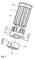
- Fig. 3
- die Verdreh-Sicherung der Stuhl-Säule in perspektivischer Explosionsdarstellung.
- Die in der Zeichnung dargestellte Stuhl-Säule weist ein Standrohr 1 und eine in diesem mittels einer Führungsbüchse 2 geführte, in Richtung einer gemeinsamen Mittel-Längs-Achse 3 verschiebbare, längenverstellbare Gasfeder 4 auf. Das Standrohr 1 weist an seinem unteren Ende einen Halte-Konus 5 zur Befestigung in einem üblichen Stuhl-Fußgestell auf.
- Die Gasfeder 4 weist ein im Wesentlichen zylindrisches Gehäuse 6 auf, das in der Führungsbüchse 2 geführt ist. Konzentrisch zur Achse 3 ist im Gehäuse 6 ein Innen-Rohr 7 angeordnet, zwischen dem und dem Gehäuse 6 ein Ringkanal 8 ausgebildet ist. An dem außerhalb des Standrohres 1 befindlichen oberen Ende des Gehäuses 6 ist in diesem ein Ventil 9 angeordnet, das mittels eines aus dem Gehäuse 6 herausragenden Betätigungsstiftes 10 betätigbar ist. Es dient zur wahlweisen Verbindung des Ringkanals 8 mit dem dem Ventil 9 benachbarten, im Innen-Rohr 7 ausgebildeten ersten Teil-Gehäuseraum 11.
- Im Innen-Rohr 7 ist eine Kolbenstange 12 konzentrisch zur Achse 3 und in deren Richtung verschiebbar angeordnet, die an dem dem Ventil 9 entgegengesetzten, im Standrohr 1 befindlichen unteren Ende des Gehäuses 6 aus diesem herausgeführt ist. Sie ist in diesem Bereich mittels einer Führungs-Dichtungs-Einheit 13 gasdicht geführt. Am im Innen-Rohr 7 befindlichen Ende der Kolbenstange 12 ist an dieser ein Kolben 14 angebracht, der abgedichtet am Innen-Rohr 7 geführt ist. Er trennt den ersten Teil-Gehäuseraum 11 von einem zwischen dem Kolben 14 und der Führungs-Dichtungs-Einheit 13 ausgebildeten zweiten Teil-Gehäuseraum 15. An dem dem Ventil 9 benachbarten Ende des Gehäuses 6 ist an diesem ein sich konusförmig verjüngender Befestigungsabschnitt 16 ausgebildet, mittels dessen die Gasfeder 4 an einer entsprechenden Aufnahme an der Unterseite eines Stuhlsitzes, beispielsweise also einem Stuhlsitzträger, befestigbar ist. An ihrem unteren, außerhalb des Gehäuses 6 liegenden Ende ist die Kolbenstange 12 über ein Axial-Lager 17 am Boden 18 des Standrohres 1 abgestützt und dort mittels einer Befestigungs-Klammer 19 lösbar befestigt.
- Der Ringkanal 8 und die Teil-Gehäuseräume 11 und 15 sind mit Gas unter verhältnismäßig hohem Druck und gegebenenfalls einer vorgegebenen Menge Öl gefüllt. Der zweite Teil-Gehäuseraum 15 ist an der Führungs-Dichtungs-Einheit 13 mittels eines Überström-Kanals 20 ständig mit dem Ringkanal 8 verbunden. Wenn das Ventil 9 durch Eindrücken des Betätigungsstiftes 10 geöffnet wird, dann wird bei ausreichender Entlastung des Gehäuses 6 die Kolbenstange ausgeschoben, d. h. das Gehäuse 6 wird aus dem Standrohr 1 nach oben herausgeschoben. Bei entsprechender Belastung des Gehäuses 6 wird dagegen das Gehäuse 6 nach unten in das Standrohr 1 eingeschoben und damit die Kolbenstange 12 in das Gehäuse 6 eingefahren. Beim Schließen des Ventils 9 durch Loslassen des Betätigungsstiftes 10 wird das Gehäuse 6 mit der Kolbenstange 12 über den im Gehäuse 6 herrschenden Druck gleichsam verriegelt, wobei bei einer Gasfüllung es sich um eine elastisch federnde Verriegelung und bei Vorhandensein einer überwiegenden Flüssigkeitsfüllung um eine weitgehend starre Verriegelung handelt. Der gesamte Aufbau und die Funktionsweise der Gasfeder 4 sind - soweit bisher beschrieben - allgemein bekannt, beispielsweise aus dem grundlegenden Patent DE 18 12 282 (entsprechend US 3,656,593). Entsprechend ist der grundsätzliche Aufbau und die Funktionsweise der Stuhlsäule aus dem Patent DE 19 31 021 bekannt.
- Die Führungsbüchse 2 weist an ihrer Außenseite Längs-Rippen 21 auf, mittels derer sie sich an der Innenwand 22 des Standrohres 1 radial zur Achse 3 abstützt. Zwischen den Längs-Rippen 21 sind entsprechende Längs-Nuten 23 ausgebildet. An dem im Innenraum des Standrohres 1 befindlichen Ende der Führungsbüchse 2 ist ein Feststell-Widerlager 24 angebracht, das im Wesentlichen aus einem Ring 25 und an diesem ausgebildeten, parallel zur Achse 3 verlaufenden, in die Längs-Nuten 23 eingeschobenen Haltestegen 26 besteht. Mittels dieser Haltestege 26 ist das Widerlager 24 fest an der Führungsbüchse 2 befestigt, und zwar insbesondere drehfest. Es ist mit der ebenfalls aus schweißbarem Kunststoff bestehenden Führungsbüchse 2 durch Ultraschallschweißen oder dergleichen verschweißt und klemmend gehalten. Die Führungsbüchse 2 selber ist ausreichend drehfest, gegebenenfalls durch zusätzliche Sicherungsmittel, in das Standrohr 1 eingepresst.
- An dem der Führungs-Dichtungs-Einheit 13 zugewandten, kolbenstangenaustrittswärtigem Ende des Gehäuses 6 ist an diesem ein Feststell-Element 27 angebracht, das ebenfalls im Wesentlichen in Form eines Ringes ausgebildet ist. Die Führungsbüchse 2, das Feststell-Widerlager 24 und das Feststell-Element 27 bilden eine Verdreh-Sicherung. Das Widerlager 24 und das Element 27 sind jeweils mit Ausschnitten 28, 29 versehen, wodurch wiederum Feststell-Stege 30, 31 gebildet werden. Die Ausschnitte 28, 29 und damit die Stege 30, 31 sind so ausgebildet, dass der Feststell-Steg 30 des Widerlagers 24 in den Ausschnitt 29 des Elements 27 und der Steg 31 des Elements 27 in den Ausschnitt 28 des Widerlagers 24 eingreift, und zwar spielfrei. Die Stege 30, 31 weisen jeweils Schrägflächen 32, 33 auf, die derart schräg zur Achse 3 angeordnet sind, dass die Ausschnitte 28, 29 sich jeweils zu ihrer offenen Seite hin erweitern. Die beim Eingriff des Elements 27 in das Widerlager 24 einander zugeordneten Schräg-Flächen 32 bzw. 33 weisen den gleichen Öffnungswinkel a zu einer achsparallelen Linie auf. Die Umfangserstreckung der Feststell-Stege 30, 31 ist derart bemessen, dass beim Eindringen des Feststell-Elements 27 in das Feststell-Widerlager 24 zwischen dem Boden 34 des Ausschnitts 28 des Widerlagers 24 und dem Feststell-Steg 31 des Feststell-Elements 27 und zwischen dem Boden 35 des Ausschnitts 29 des Feststell-Elements und dem Feststell-Steg 30 ein Spiel 36 bzw. 37 in Richtung der Achse 3 verbleibt. In diesem Fall liegen also die Schrägflächen 32, 33 jeweils fest aneinander, d. h. das Feststell-Element 27 hat kein tangentiales Spiel, also kein Drehspiel, gegenüber dem Widerlager 24.
- Am Ende des vollständigen Ausfahrens des Gehäuses 6 der Gasfeder 4 aus dem Standrohr 1 kann durch entsprechendes Drehen des Gehäuses 6 der Gasfeder 4 bzw. des an ihr befestigten Sitzes gegenüber dem Standrohr 1 um die Achse 3 das Feststell-Element 27 in eine derartige Position gegenüber dem Feststell-Widerlager 24 gebracht werden, dass es in der geschilderten Weise in dieses eingreift und dadurch mit diesem drehfest verbunden wird. Der am Befestigungsabschnitt 16 befestigte Stuhlsitz kann sich daher in dieser Position gegenüber dem am Standrohr 1 befestigten Fußgestell nicht mehr verdrehen.
- Der Öffnungswinkel a wird so gewählt, dass bei entsprechend großen, zwischen Gehäuse 6 und Standrohr 1 wirkenden Drehmomenten das Feststell-Element 27 und das Feststell-Widerlager 24 über die Schräg-Flächen 32, 33 in Richtung der Achse 3 auseinandergedrückt werden. Die Dimensionierung erfolgt über eine Abstimmung der in ausgefahrenem Zustand zwischen der Kolbenstange 12 und dem Gehäuse 6 aufgrund des inneren Gasdrucks bestehenden Ausschubkraft und dem mittleren Radius r der Schräg-Flächen 32, 33 und dem als zulässig angesehenen Drehmoment. Die Verdreh-Sicherung arbeitet also formschlüssig bis zum Erreichen des vorgegebenen Drehmomentes. Für den Öffnungswinkel a gilt: 5° ≤a ≤25° und bevorzugt 10° ≤a ≤15°.
Claims (11)
- Höhenverstellbare Stuhl-Säule- mit einem Standrohr (1) mit einer Mittel-Längs-Achse (3),- mit einer im Standrohr (1) koaxial zur Mittel-Längs-Achse (3) angeordneten Gasfeder (4), die-- ein im Standrohr (1) in Richtung der Mittel-Längs-Achse (3) bis in eine ausgefahrene Stellung verschiebbares Gehäuse (6) und-- eine im Standrohr (1) festgelegte Kolbenstange (12) aufweist und- mit einer Verdreh-Sicherung (2, 24, 27), die das Gehäuse (6) mit dem Standrohr (1) gegen Verdrehen festlegt,dadurch gekennzeichnet,
dass das Gehäuse (6) gegenüber dem Standrohr (1) drehbar ausgebildet ist und
dass die Verdreh-Sicherung (2, 24, 27) derart ausgebildet ist, dass sie das Gehäuse (6) nur in seiner vollständig ausgefahrenen Stellung gegenüber dem Standrohr (1) gegen Verdrehen festlegt. - Höhenverstellbare Stuhl-Säule nach Anspruch 1, dadurch gekennzeichnet,
dass die Verdreh-Sicherung (2, 24, 27) formschlüssig wirkend ausgebildet ist. - Höhenverstellbare Stuhl-Säule nach Anspruch 1 oder 2, dadurch gekennzeichnet,
dass die Verdreh-Sicherung (2, 24, 27) derart ausgebildet ist, dass sie bei Überschreiten eines vorgegebenen Drehmoments zwischen dem Gehäuse (6) und dem Standrohr (1) sich löst. - Höhenverstellbare Stuhl-Säule nach einem der Ansprüche 1 bis 3, dadurch gekennzeichnet,
dass die Verdreh-Sicherung (2, 24, 27) ein mit dem Gehäuse (6) verbundenes Feststell-Element (27) und ein mit dem Standrohr (1) verbundenes Feststell-Widerlager (24) aufweist. - Höhenverstellbare Stuhl-Säule nach Anspruch 4, dadurch gekennzeichnet,
dass das Feststell-Element (27) und/oder das Feststell-Widerlager (24) mindestens einen Ausschnitt (28, 29) und mindestens einen diesem zugeordneten und angepassten Feststell-Steg (30, 31) aufweisen. - Höhenverstellbare Stuhl-Säule nach Anspruch 5, dadurch gekennzeichnet,
dass der mindestens eine Ausschnitt (28, 29) und der mindestens eine Feststell-Steg (30, 31) einander angepasste Schräg-Flächen (32, 33) mit einem Öffnungswinkel (a) aufweisen. - Höhenverstellbare Stuhl-Säule nach Anspruch 6, dadurch gekennzeichnet,
dass jeder Ausschnitt (28, 29) und jeder Feststell-Steg (30, 31) einander angepasste Schräg-Flächen (32, 33) aufweisen. - Höhenverstellbare Stuhl-Säule nach Anspruch 6 oder 7, dadurch gekennzeichnet,
dass für den Öffnungswinkel (a) gilt 5° ≤a ≤25° und bevorzugt 10° ≤a ≤15°. - Höhenverstellbare Stuhl-Säule nach einem der Ansprüche 6 bis 8, dadurch gekennzeichnet,
dass in der ausgefahrenen Stellung alle Schräg-Flächen (32, 33) dicht aneinander liegen. - Höhenverstellbare Stuhl-Säule nach Anspruch 9, dadurch gekennzeichnet,
dass in der ausgefahrenen Stellung zwischen dem Boden (34, 35) eines Ausschnitts (28, 29) und dem in den Ausschnitt (28, 29) eingreifenden Feststell-Steg (30, 31) ein Spiel (36, 37) besteht. - Höhenverstellbare Stuhl-Säule nach Anspruch 5 oder 6, dadurch gekennzeichnet, dass jedem Feststell-Steg (30, 31) nur ein angepasster Ausschnitt (28, 29) zugeordnet ist.
Applications Claiming Priority (2)
| Application Number | Priority Date | Filing Date | Title |
|---|---|---|---|
| DE102004003624A DE102004003624A1 (de) | 2004-01-24 | 2004-01-24 | Höhenverstellbare Stuhl-Säule |
| DE102004003624 | 2004-01-24 |
Publications (2)
| Publication Number | Publication Date |
|---|---|
| EP1559349A1 EP1559349A1 (de) | 2005-08-03 |
| EP1559349B1 true EP1559349B1 (de) | 2006-06-28 |
Family
ID=34638750
Family Applications (1)
| Application Number | Title | Priority Date | Filing Date |
|---|---|---|---|
| EP04029283A Expired - Lifetime EP1559349B1 (de) | 2004-01-24 | 2004-12-10 | Höhenverstellbare Stuhl-Säule |
Country Status (6)
| Country | Link |
|---|---|
| US (1) | US7328875B2 (de) |
| EP (1) | EP1559349B1 (de) |
| JP (1) | JP2005205207A (de) |
| AT (1) | ATE331449T1 (de) |
| CA (1) | CA2490382A1 (de) |
| DE (2) | DE102004003624A1 (de) |
Families Citing this family (8)
| Publication number | Priority date | Publication date | Assignee | Title |
|---|---|---|---|---|
| DE102004034220B3 (de) * | 2004-07-14 | 2006-02-23 | Stabilus Gmbh | Objektträgersäule |
| DE202005017987U1 (de) * | 2005-11-17 | 2006-01-12 | Kintec-Solution Gmbh | Sessel |
| TW200942199A (en) * | 2008-04-11 | 2009-10-16 | Hong-Yi Huang | Pneumatic lifter |
| DE102008047745B4 (de) * | 2008-09-17 | 2015-04-30 | Stabilus Gmbh | Höhenverstellbares Möbelstück |
| DE102009058647A1 (de) * | 2009-12-16 | 2011-06-22 | Stabilus GmbH, 56070 | Objektträgersäule |
| WO2013030997A1 (ja) * | 2011-08-31 | 2013-03-07 | Higashi Kazuo | 伸縮装置 |
| EP3001932B1 (de) * | 2014-09-30 | 2018-04-25 | Innotec Motion GmbH | Vorrichtung zur höhenverstellung einer sitzfläche eines sitzmöbels |
| CN106051020A (zh) * | 2016-07-29 | 2016-10-26 | 常州市莱特气弹簧有限公司 | 气动杆的后顶套 |
Family Cites Families (11)
| Publication number | Priority date | Publication date | Assignee | Title |
|---|---|---|---|---|
| DE1812282C3 (de) | 1968-12-03 | 1981-07-30 | Fritz Bauer + Söhne oHG, 8503 Altdorf | Hubvorrichtung zum stufenlosen Höhenverstellen von Tischplatten, Stuhlsitzen u.dgl. |
| DE1931021A1 (de) | 1969-06-19 | 1971-01-07 | Suspa Federungstech | Hubvorrichtung zum stufenlosen Hoeherverstellen insbesondere von Arbeitsplatten,z.B. Tischplatten u.dgl. |
| GB2083349B (en) * | 1980-09-03 | 1984-03-14 | Project Office Furniture Ltd | Swivel restrictor apparatus |
| SE449424B (sv) * | 1983-08-22 | 1987-05-04 | Svenska Vision Ab | Teleskopuppbyggd stativpelare |
| DE3420528A1 (de) * | 1984-06-01 | 1985-12-05 | Stabilus Gmbh, 5400 Koblenz | Stufenlos verstellbare hubvorrichtung |
| US5031869A (en) * | 1987-05-05 | 1991-07-16 | Illinois Tool Works Inc. | Control assembly for chair height adjustment |
| DE4233407A1 (de) * | 1992-10-05 | 1994-04-07 | Stabilus Gmbh | Führung für teleskopartig ineinander verschiebbare zylindrische Teile |
| DE4313766A1 (de) * | 1993-04-27 | 1994-11-03 | Suspa Compart Ag | Längenverstellbare Säule für Stühle, Tische od. dgl. |
| DE4428259C2 (de) * | 1994-08-10 | 1997-04-10 | Stabilus Gmbh | Objektträgersäule |
| DE19628721C2 (de) * | 1996-07-17 | 1999-01-21 | Stabilus Gmbh | Höhenverstellbare Säule |
| US5988754A (en) * | 1999-02-10 | 1999-11-23 | Steelcase Development Inc. | Stool with foot support |
-
2004
- 2004-01-24 DE DE102004003624A patent/DE102004003624A1/de not_active Withdrawn
- 2004-12-10 DE DE502004000877T patent/DE502004000877D1/de not_active Expired - Lifetime
- 2004-12-10 EP EP04029283A patent/EP1559349B1/de not_active Expired - Lifetime
- 2004-12-10 AT AT04029283T patent/ATE331449T1/de not_active IP Right Cessation
- 2004-12-16 CA CA002490382A patent/CA2490382A1/en not_active Abandoned
-
2005
- 2005-01-05 US US11/028,607 patent/US7328875B2/en not_active Expired - Fee Related
- 2005-01-12 JP JP2005005236A patent/JP2005205207A/ja active Pending
Also Published As
| Publication number | Publication date |
|---|---|
| EP1559349A1 (de) | 2005-08-03 |
| DE102004003624A1 (de) | 2005-08-11 |
| CA2490382A1 (en) | 2005-07-24 |
| DE502004000877D1 (de) | 2006-08-10 |
| JP2005205207A (ja) | 2005-08-04 |
| US20050161559A1 (en) | 2005-07-28 |
| US7328875B2 (en) | 2008-02-12 |
| ATE331449T1 (de) | 2006-07-15 |
Similar Documents
| Publication | Publication Date | Title |
|---|---|---|
| EP3021974B1 (de) | Zentrifuge | |
| DE3420528C2 (de) | ||
| DE1812282C3 (de) | Hubvorrichtung zum stufenlosen Höhenverstellen von Tischplatten, Stuhlsitzen u.dgl. | |
| DE3429424C2 (de) | ||
| EP0641532B1 (de) | Längenverstellbare Säule für Stühle, Tische o.dgl. | |
| EP2242944B1 (de) | Hubventil, insbesondere für die prozesstechnik | |
| DE3034057A1 (de) | Ausruecklager | |
| DE2324432A1 (de) | In der hoehe verstellbares pult oder tisch | |
| DE3413804C2 (de) | ||
| EP1559349B1 (de) | Höhenverstellbare Stuhl-Säule | |
| DE3803407A1 (de) | Hoehenverstellvorrichtung | |
| EP1557114B1 (de) | Höhenverstellbare Stuhl-Säule | |
| DE60024207T2 (de) | Drehbaugruppe für einen drehstuhl | |
| EP0651175A1 (de) | Längenverstellbare Gasfeder | |
| DE19515368A1 (de) | Längenverstellbare Gasfeder | |
| EP0564776A1 (de) | Längenverstellbare Gasfeder und Stuhl mit einer solchen Gasfeder | |
| WO2000047852A1 (de) | Scharnier mit arretierung | |
| DE29724446U1 (de) | Längenverstellbare Säule für Stühle o.dgl. | |
| DE7434102U (de) | Höhenverstellbare Säule | |
| EP0667462B1 (de) | Längenverstellbare Säule für Stühle, Tische od. dgl. und Feder-Sicherungsklammer hierfür | |
| DE29608147U1 (de) | Stuhl-Gasfeder | |
| DE2705259A1 (de) | Hubvorrichtung zum stufenlosen hoehenverstellen von stuhlsitzen o.dgl. | |
| EP0151899A1 (de) | Standsäule | |
| DE9402272U1 (de) | Längenverstellbare Säule für Stühle, Tische o.dgl. und Feder-Sicherungsklammer hierfür | |
| CH720298A2 (de) | Betätigungsmechanismus, Möbelarretieranordnung, Möbel und Verfahren zum selektiven Hemmen einer Bewegung eines Möbels. |
Legal Events
| Date | Code | Title | Description |
|---|---|---|---|
| PUAI | Public reference made under article 153(3) epc to a published international application that has entered the european phase |
Free format text: ORIGINAL CODE: 0009012 |
|
| AK | Designated contracting states |
Kind code of ref document: A1 Designated state(s): AT BE BG CH CY CZ DE DK EE ES FI FR GB GR HU IE IS IT LI LT LU MC NL PL PT RO SE SI SK TR |
|
| AX | Request for extension of the european patent |
Extension state: AL BA HR LV MK YU |
|
| 17P | Request for examination filed |
Effective date: 20051025 |
|
| GRAP | Despatch of communication of intention to grant a patent |
Free format text: ORIGINAL CODE: EPIDOSNIGR1 |
|
| GRAS | Grant fee paid |
Free format text: ORIGINAL CODE: EPIDOSNIGR3 |
|
| AKX | Designation fees paid |
Designated state(s): AT BE BG CH CY CZ DE DK EE ES FI FR GB GR HU IE IS IT LI LT LU MC NL PL PT RO SE SI SK TR |
|
| GRAA | (expected) grant |
Free format text: ORIGINAL CODE: 0009210 |
|
| AK | Designated contracting states |
Kind code of ref document: B1 Designated state(s): AT BE BG CH CY CZ DE DK EE ES FI FR GB GR HU IE IS IT LI LT LU MC NL PL PT RO SE SI SK TR |
|
| PG25 | Lapsed in a contracting state [announced via postgrant information from national office to epo] |
Ref country code: IT Free format text: LAPSE BECAUSE OF FAILURE TO SUBMIT A TRANSLATION OF THE DESCRIPTION OR TO PAY THE FEE WITHIN THE PRESCRIBED TIME-LIMIT;WARNING: LAPSES OF ITALIAN PATENTS WITH EFFECTIVE DATE BEFORE 2007 MAY HAVE OCCURRED AT ANY TIME BEFORE 2007. THE CORRECT EFFECTIVE DATE MAY BE DIFFERENT FROM THE ONE RECORDED. Effective date: 20060628 Ref country code: NL Free format text: LAPSE BECAUSE OF FAILURE TO SUBMIT A TRANSLATION OF THE DESCRIPTION OR TO PAY THE FEE WITHIN THE PRESCRIBED TIME-LIMIT Effective date: 20060628 Ref country code: RO Free format text: LAPSE BECAUSE OF FAILURE TO SUBMIT A TRANSLATION OF THE DESCRIPTION OR TO PAY THE FEE WITHIN THE PRESCRIBED TIME-LIMIT Effective date: 20060628 Ref country code: FI Free format text: LAPSE BECAUSE OF FAILURE TO SUBMIT A TRANSLATION OF THE DESCRIPTION OR TO PAY THE FEE WITHIN THE PRESCRIBED TIME-LIMIT Effective date: 20060628 Ref country code: GB Free format text: LAPSE BECAUSE OF FAILURE TO SUBMIT A TRANSLATION OF THE DESCRIPTION OR TO PAY THE FEE WITHIN THE PRESCRIBED TIME-LIMIT Effective date: 20060628 Ref country code: PL Free format text: LAPSE BECAUSE OF FAILURE TO SUBMIT A TRANSLATION OF THE DESCRIPTION OR TO PAY THE FEE WITHIN THE PRESCRIBED TIME-LIMIT Effective date: 20060628 Ref country code: SI Free format text: LAPSE BECAUSE OF FAILURE TO SUBMIT A TRANSLATION OF THE DESCRIPTION OR TO PAY THE FEE WITHIN THE PRESCRIBED TIME-LIMIT Effective date: 20060628 Ref country code: SK Free format text: LAPSE BECAUSE OF FAILURE TO SUBMIT A TRANSLATION OF THE DESCRIPTION OR TO PAY THE FEE WITHIN THE PRESCRIBED TIME-LIMIT Effective date: 20060628 Ref country code: IE Free format text: LAPSE BECAUSE OF FAILURE TO SUBMIT A TRANSLATION OF THE DESCRIPTION OR TO PAY THE FEE WITHIN THE PRESCRIBED TIME-LIMIT Effective date: 20060628 Ref country code: CZ Free format text: LAPSE BECAUSE OF FAILURE TO SUBMIT A TRANSLATION OF THE DESCRIPTION OR TO PAY THE FEE WITHIN THE PRESCRIBED TIME-LIMIT Effective date: 20060628 Ref country code: LT Free format text: LAPSE BECAUSE OF FAILURE TO SUBMIT A TRANSLATION OF THE DESCRIPTION OR TO PAY THE FEE WITHIN THE PRESCRIBED TIME-LIMIT Effective date: 20060628 |
|
| REG | Reference to a national code |
Ref country code: GB Ref legal event code: FG4D Free format text: NOT ENGLISH |
|
| REG | Reference to a national code |
Ref country code: CH Ref legal event code: EP |
|
| REG | Reference to a national code |
Ref country code: IE Ref legal event code: FG4D Free format text: LANGUAGE OF EP DOCUMENT: GERMAN |
|
| REF | Corresponds to: |
Ref document number: 502004000877 Country of ref document: DE Date of ref document: 20060810 Kind code of ref document: P |
|
| PG25 | Lapsed in a contracting state [announced via postgrant information from national office to epo] |
Ref country code: DK Free format text: LAPSE BECAUSE OF FAILURE TO SUBMIT A TRANSLATION OF THE DESCRIPTION OR TO PAY THE FEE WITHIN THE PRESCRIBED TIME-LIMIT Effective date: 20060928 Ref country code: SE Free format text: LAPSE BECAUSE OF FAILURE TO SUBMIT A TRANSLATION OF THE DESCRIPTION OR TO PAY THE FEE WITHIN THE PRESCRIBED TIME-LIMIT Effective date: 20060928 |
|
| PG25 | Lapsed in a contracting state [announced via postgrant information from national office to epo] |
Ref country code: ES Free format text: LAPSE BECAUSE OF FAILURE TO SUBMIT A TRANSLATION OF THE DESCRIPTION OR TO PAY THE FEE WITHIN THE PRESCRIBED TIME-LIMIT Effective date: 20061009 |
|
| PG25 | Lapsed in a contracting state [announced via postgrant information from national office to epo] |
Ref country code: PT Free format text: LAPSE BECAUSE OF FAILURE TO SUBMIT A TRANSLATION OF THE DESCRIPTION OR TO PAY THE FEE WITHIN THE PRESCRIBED TIME-LIMIT Effective date: 20061128 |
|
| NLV1 | Nl: lapsed or annulled due to failure to fulfill the requirements of art. 29p and 29m of the patents act | ||
| PG25 | Lapsed in a contracting state [announced via postgrant information from national office to epo] |
Ref country code: BE Free format text: LAPSE BECAUSE OF NON-PAYMENT OF DUE FEES Effective date: 20061231 Ref country code: MC Free format text: LAPSE BECAUSE OF NON-PAYMENT OF DUE FEES Effective date: 20061231 |
|
| GBV | Gb: ep patent (uk) treated as always having been void in accordance with gb section 77(7)/1977 [no translation filed] |
Effective date: 20060628 |
|
| REG | Reference to a national code |
Ref country code: IE Ref legal event code: FD4D |
|
| PLBE | No opposition filed within time limit |
Free format text: ORIGINAL CODE: 0009261 |
|
| STAA | Information on the status of an ep patent application or granted ep patent |
Free format text: STATUS: NO OPPOSITION FILED WITHIN TIME LIMIT |
|
| EN | Fr: translation not filed | ||
| 26N | No opposition filed |
Effective date: 20070329 |
|
| BERE | Be: lapsed |
Owner name: SUSPA HOLDING G.M.B.H. Effective date: 20061231 |
|
| PG25 | Lapsed in a contracting state [announced via postgrant information from national office to epo] |
Ref country code: AT Free format text: LAPSE BECAUSE OF NON-PAYMENT OF DUE FEES Effective date: 20061210 |
|
| PG25 | Lapsed in a contracting state [announced via postgrant information from national office to epo] |
Ref country code: FR Free format text: LAPSE BECAUSE OF FAILURE TO SUBMIT A TRANSLATION OF THE DESCRIPTION OR TO PAY THE FEE WITHIN THE PRESCRIBED TIME-LIMIT Effective date: 20070511 Ref country code: GR Free format text: LAPSE BECAUSE OF FAILURE TO SUBMIT A TRANSLATION OF THE DESCRIPTION OR TO PAY THE FEE WITHIN THE PRESCRIBED TIME-LIMIT Effective date: 20060929 |
|
| PG25 | Lapsed in a contracting state [announced via postgrant information from national office to epo] |
Ref country code: EE Free format text: LAPSE BECAUSE OF FAILURE TO SUBMIT A TRANSLATION OF THE DESCRIPTION OR TO PAY THE FEE WITHIN THE PRESCRIBED TIME-LIMIT Effective date: 20060628 Ref country code: BG Free format text: LAPSE BECAUSE OF FAILURE TO SUBMIT A TRANSLATION OF THE DESCRIPTION OR TO PAY THE FEE WITHIN THE PRESCRIBED TIME-LIMIT Effective date: 20060928 |
|
| PG25 | Lapsed in a contracting state [announced via postgrant information from national office to epo] |
Ref country code: LU Free format text: LAPSE BECAUSE OF NON-PAYMENT OF DUE FEES Effective date: 20061210 Ref country code: IS Free format text: LAPSE BECAUSE OF FAILURE TO SUBMIT A TRANSLATION OF THE DESCRIPTION OR TO PAY THE FEE WITHIN THE PRESCRIBED TIME-LIMIT Effective date: 20060628 Ref country code: HU Free format text: LAPSE BECAUSE OF FAILURE TO SUBMIT A TRANSLATION OF THE DESCRIPTION OR TO PAY THE FEE WITHIN THE PRESCRIBED TIME-LIMIT Effective date: 20061229 Ref country code: TR Free format text: LAPSE BECAUSE OF FAILURE TO SUBMIT A TRANSLATION OF THE DESCRIPTION OR TO PAY THE FEE WITHIN THE PRESCRIBED TIME-LIMIT Effective date: 20060628 |
|
| PG25 | Lapsed in a contracting state [announced via postgrant information from national office to epo] |
Ref country code: CY Free format text: LAPSE BECAUSE OF FAILURE TO SUBMIT A TRANSLATION OF THE DESCRIPTION OR TO PAY THE FEE WITHIN THE PRESCRIBED TIME-LIMIT Effective date: 20060628 Ref country code: FR Free format text: LAPSE BECAUSE OF FAILURE TO SUBMIT A TRANSLATION OF THE DESCRIPTION OR TO PAY THE FEE WITHIN THE PRESCRIBED TIME-LIMIT Effective date: 20060628 |
|
| REG | Reference to a national code |
Ref country code: CH Ref legal event code: PL |
|
| PG25 | Lapsed in a contracting state [announced via postgrant information from national office to epo] |
Ref country code: LI Free format text: LAPSE BECAUSE OF NON-PAYMENT OF DUE FEES Effective date: 20081231 Ref country code: CH Free format text: LAPSE BECAUSE OF NON-PAYMENT OF DUE FEES Effective date: 20081231 |
|
| PGFP | Annual fee paid to national office [announced via postgrant information from national office to epo] |
Ref country code: DE Payment date: 20171231 Year of fee payment: 14 |
|
| REG | Reference to a national code |
Ref country code: DE Ref legal event code: R119 Ref document number: 502004000877 Country of ref document: DE |
|
| PG25 | Lapsed in a contracting state [announced via postgrant information from national office to epo] |
Ref country code: DE Free format text: LAPSE BECAUSE OF NON-PAYMENT OF DUE FEES Effective date: 20190702 |