EP1558779B1 - Verfahren und vorrichtung zum entzundern und/oder reinigen eines metallstrangs - Google Patents
Verfahren und vorrichtung zum entzundern und/oder reinigen eines metallstrangs Download PDFInfo
- Publication number
- EP1558779B1 EP1558779B1 EP03753485A EP03753485A EP1558779B1 EP 1558779 B1 EP1558779 B1 EP 1558779B1 EP 03753485 A EP03753485 A EP 03753485A EP 03753485 A EP03753485 A EP 03753485A EP 1558779 B1 EP1558779 B1 EP 1558779B1
- Authority
- EP
- European Patent Office
- Prior art keywords
- descaling
- plasma
- cleaning
- metal strip
- metal strand
- Prior art date
- Legal status (The legal status is an assumption and is not a legal conclusion. Google has not performed a legal analysis and makes no representation as to the accuracy of the status listed.)
- Revoked
Links
- 238000004140 cleaning Methods 0.000 title claims abstract description 83
- 238000000034 method Methods 0.000 title claims abstract description 37
- 238000005058 metal casting Methods 0.000 title 1
- 239000002184 metal Substances 0.000 claims abstract description 128
- 229910052751 metal Inorganic materials 0.000 claims abstract description 128
- 229910000831 Steel Inorganic materials 0.000 claims abstract description 18
- 239000010959 steel Substances 0.000 claims abstract description 18
- 230000008569 process Effects 0.000 claims abstract description 16
- 229910001220 stainless steel Inorganic materials 0.000 claims abstract description 8
- 239000010935 stainless steel Substances 0.000 claims abstract description 6
- 238000000576 coating method Methods 0.000 claims description 19
- 239000011248 coating agent Substances 0.000 claims description 18
- 229910001338 liquidmetal Inorganic materials 0.000 claims description 10
- 238000010438 heat treatment Methods 0.000 claims description 9
- 238000005097 cold rolling Methods 0.000 claims description 7
- 238000005246 galvanizing Methods 0.000 claims description 7
- 230000006698 induction Effects 0.000 claims description 6
- 239000000463 material Substances 0.000 claims description 4
- 238000011109 contamination Methods 0.000 claims description 2
- 230000001105 regulatory effect Effects 0.000 claims 3
- 238000010276 construction Methods 0.000 claims 1
- 238000005452 bending Methods 0.000 description 10
- 238000005554 pickling Methods 0.000 description 8
- 238000012360 testing method Methods 0.000 description 8
- 238000005516 engineering process Methods 0.000 description 7
- 238000003860 storage Methods 0.000 description 7
- 239000002253 acid Substances 0.000 description 6
- 230000008901 benefit Effects 0.000 description 5
- 238000009966 trimming Methods 0.000 description 5
- VEXZGXHMUGYJMC-UHFFFAOYSA-N Hydrochloric acid Chemical compound Cl VEXZGXHMUGYJMC-UHFFFAOYSA-N 0.000 description 4
- 230000007613 environmental effect Effects 0.000 description 4
- 239000007788 liquid Substances 0.000 description 4
- 238000005096 rolling process Methods 0.000 description 4
- 229910001209 Low-carbon steel Inorganic materials 0.000 description 3
- 150000007513 acids Chemical class 0.000 description 3
- UQSXHKLRYXJYBZ-UHFFFAOYSA-N iron oxide Inorganic materials [Fe]=O UQSXHKLRYXJYBZ-UHFFFAOYSA-N 0.000 description 3
- 238000012545 processing Methods 0.000 description 3
- 238000003466 welding Methods 0.000 description 3
- QAOWNCQODCNURD-UHFFFAOYSA-N Sulfuric acid Chemical compound OS(O)(=O)=O QAOWNCQODCNURD-UHFFFAOYSA-N 0.000 description 2
- 238000000137 annealing Methods 0.000 description 2
- 238000013459 approach Methods 0.000 description 2
- 238000005265 energy consumption Methods 0.000 description 2
- 230000006872 improvement Effects 0.000 description 2
- 238000012432 intermediate storage Methods 0.000 description 2
- XEEYBQQBJWHFJM-UHFFFAOYSA-N iron Substances [Fe] XEEYBQQBJWHFJM-UHFFFAOYSA-N 0.000 description 2
- 235000013980 iron oxide Nutrition 0.000 description 2
- VBMVTYDPPZVILR-UHFFFAOYSA-N iron(2+);oxygen(2-) Chemical class [O-2].[Fe+2] VBMVTYDPPZVILR-UHFFFAOYSA-N 0.000 description 2
- 230000001681 protective effect Effects 0.000 description 2
- 239000000126 substance Substances 0.000 description 2
- VYZAMTAEIAYCRO-UHFFFAOYSA-N Chromium Chemical compound [Cr] VYZAMTAEIAYCRO-UHFFFAOYSA-N 0.000 description 1
- GRYLNZFGIOXLOG-UHFFFAOYSA-N Nitric acid Chemical compound O[N+]([O-])=O GRYLNZFGIOXLOG-UHFFFAOYSA-N 0.000 description 1
- 241001474791 Proboscis Species 0.000 description 1
- 230000001680 brushing effect Effects 0.000 description 1
- 230000008859 change Effects 0.000 description 1
- 238000006243 chemical reaction Methods 0.000 description 1
- 229910052804 chromium Inorganic materials 0.000 description 1
- 239000011651 chromium Substances 0.000 description 1
- 238000001816 cooling Methods 0.000 description 1
- 238000005260 corrosion Methods 0.000 description 1
- 230000007797 corrosion Effects 0.000 description 1
- 230000008878 coupling Effects 0.000 description 1
- 238000010168 coupling process Methods 0.000 description 1
- 238000005859 coupling reaction Methods 0.000 description 1
- 238000011161 development Methods 0.000 description 1
- 230000018109 developmental process Effects 0.000 description 1
- 239000012467 final product Substances 0.000 description 1
- 238000005098 hot rolling Methods 0.000 description 1
- 238000004519 manufacturing process Methods 0.000 description 1
- 229910017604 nitric acid Inorganic materials 0.000 description 1
- 230000003647 oxidation Effects 0.000 description 1
- 238000007254 oxidation reaction Methods 0.000 description 1
- 230000035515 penetration Effects 0.000 description 1
- 235000021110 pickles Nutrition 0.000 description 1
- 238000000746 purification Methods 0.000 description 1
- 230000008929 regeneration Effects 0.000 description 1
- 238000011069 regeneration method Methods 0.000 description 1
- 230000004044 response Effects 0.000 description 1
- 230000000717 retained effect Effects 0.000 description 1
- 238000007665 sagging Methods 0.000 description 1
- 238000011144 upstream manufacturing Methods 0.000 description 1
- 239000002351 wastewater Substances 0.000 description 1
Images


Classifications
-
- B—PERFORMING OPERATIONS; TRANSPORTING
- B08—CLEANING
- B08B—CLEANING IN GENERAL; PREVENTION OF FOULING IN GENERAL
- B08B7/00—Cleaning by methods not provided for in a single other subclass or a single group in this subclass
- B08B7/0035—Cleaning by methods not provided for in a single other subclass or a single group in this subclass by radiant energy, e.g. UV, laser, light beam or the like
-
- B—PERFORMING OPERATIONS; TRANSPORTING
- B21—MECHANICAL METAL-WORKING WITHOUT ESSENTIALLY REMOVING MATERIAL; PUNCHING METAL
- B21B—ROLLING OF METAL
- B21B45/00—Devices for surface or other treatment of work, specially combined with or arranged in, or specially adapted for use in connection with, metal-rolling mills
- B21B45/04—Devices for surface or other treatment of work, specially combined with or arranged in, or specially adapted for use in connection with, metal-rolling mills for de-scaling, e.g. by brushing
- B21B45/06—Devices for surface or other treatment of work, specially combined with or arranged in, or specially adapted for use in connection with, metal-rolling mills for de-scaling, e.g. by brushing of strip material
-
- C—CHEMISTRY; METALLURGY
- C23—COATING METALLIC MATERIAL; COATING MATERIAL WITH METALLIC MATERIAL; CHEMICAL SURFACE TREATMENT; DIFFUSION TREATMENT OF METALLIC MATERIAL; COATING BY VACUUM EVAPORATION, BY SPUTTERING, BY ION IMPLANTATION OR BY CHEMICAL VAPOUR DEPOSITION, IN GENERAL; INHIBITING CORROSION OF METALLIC MATERIAL OR INCRUSTATION IN GENERAL
- C23C—COATING METALLIC MATERIAL; COATING MATERIAL WITH METALLIC MATERIAL; SURFACE TREATMENT OF METALLIC MATERIAL BY DIFFUSION INTO THE SURFACE, BY CHEMICAL CONVERSION OR SUBSTITUTION; COATING BY VACUUM EVAPORATION, BY SPUTTERING, BY ION IMPLANTATION OR BY CHEMICAL VAPOUR DEPOSITION, IN GENERAL
- C23C2/00—Hot-dipping or immersion processes for applying the coating material in the molten state without affecting the shape; Apparatus therefor
- C23C2/003—Apparatus
- C23C2/0038—Apparatus characterised by the pre-treatment chambers located immediately upstream of the bath or occurring locally before the dipping process
-
- C—CHEMISTRY; METALLURGY
- C23—COATING METALLIC MATERIAL; COATING MATERIAL WITH METALLIC MATERIAL; CHEMICAL SURFACE TREATMENT; DIFFUSION TREATMENT OF METALLIC MATERIAL; COATING BY VACUUM EVAPORATION, BY SPUTTERING, BY ION IMPLANTATION OR BY CHEMICAL VAPOUR DEPOSITION, IN GENERAL; INHIBITING CORROSION OF METALLIC MATERIAL OR INCRUSTATION IN GENERAL
- C23C—COATING METALLIC MATERIAL; COATING MATERIAL WITH METALLIC MATERIAL; SURFACE TREATMENT OF METALLIC MATERIAL BY DIFFUSION INTO THE SURFACE, BY CHEMICAL CONVERSION OR SUBSTITUTION; COATING BY VACUUM EVAPORATION, BY SPUTTERING, BY ION IMPLANTATION OR BY CHEMICAL VAPOUR DEPOSITION, IN GENERAL
- C23C2/00—Hot-dipping or immersion processes for applying the coating material in the molten state without affecting the shape; Apparatus therefor
- C23C2/02—Pretreatment of the material to be coated, e.g. for coating on selected surface areas
- C23C2/022—Pretreatment of the material to be coated, e.g. for coating on selected surface areas by heating
-
- C—CHEMISTRY; METALLURGY
- C23—COATING METALLIC MATERIAL; COATING MATERIAL WITH METALLIC MATERIAL; CHEMICAL SURFACE TREATMENT; DIFFUSION TREATMENT OF METALLIC MATERIAL; COATING BY VACUUM EVAPORATION, BY SPUTTERING, BY ION IMPLANTATION OR BY CHEMICAL VAPOUR DEPOSITION, IN GENERAL; INHIBITING CORROSION OF METALLIC MATERIAL OR INCRUSTATION IN GENERAL
- C23C—COATING METALLIC MATERIAL; COATING MATERIAL WITH METALLIC MATERIAL; SURFACE TREATMENT OF METALLIC MATERIAL BY DIFFUSION INTO THE SURFACE, BY CHEMICAL CONVERSION OR SUBSTITUTION; COATING BY VACUUM EVAPORATION, BY SPUTTERING, BY ION IMPLANTATION OR BY CHEMICAL VAPOUR DEPOSITION, IN GENERAL
- C23C2/00—Hot-dipping or immersion processes for applying the coating material in the molten state without affecting the shape; Apparatus therefor
- C23C2/02—Pretreatment of the material to be coated, e.g. for coating on selected surface areas
- C23C2/024—Pretreatment of the material to be coated, e.g. for coating on selected surface areas by cleaning or etching
-
- C—CHEMISTRY; METALLURGY
- C23—COATING METALLIC MATERIAL; COATING MATERIAL WITH METALLIC MATERIAL; CHEMICAL SURFACE TREATMENT; DIFFUSION TREATMENT OF METALLIC MATERIAL; COATING BY VACUUM EVAPORATION, BY SPUTTERING, BY ION IMPLANTATION OR BY CHEMICAL VAPOUR DEPOSITION, IN GENERAL; INHIBITING CORROSION OF METALLIC MATERIAL OR INCRUSTATION IN GENERAL
- C23G—CLEANING OR DE-GREASING OF METALLIC MATERIAL BY CHEMICAL METHODS OTHER THAN ELECTROLYSIS
- C23G5/00—Cleaning or de-greasing metallic material by other methods; Apparatus for cleaning or de-greasing metallic material with organic solvents
-
- B—PERFORMING OPERATIONS; TRANSPORTING
- B21—MECHANICAL METAL-WORKING WITHOUT ESSENTIALLY REMOVING MATERIAL; PUNCHING METAL
- B21B—ROLLING OF METAL
- B21B1/00—Metal-rolling methods or mills for making semi-finished products of solid or profiled cross-section; Sequence of operations in milling trains; Layout of rolling-mill plant, e.g. grouping of stands; Succession of passes or of sectional pass alternations
- B21B1/22—Metal-rolling methods or mills for making semi-finished products of solid or profiled cross-section; Sequence of operations in milling trains; Layout of rolling-mill plant, e.g. grouping of stands; Succession of passes or of sectional pass alternations for rolling plates, strips, bands or sheets of indefinite length
- B21B1/24—Metal-rolling methods or mills for making semi-finished products of solid or profiled cross-section; Sequence of operations in milling trains; Layout of rolling-mill plant, e.g. grouping of stands; Succession of passes or of sectional pass alternations for rolling plates, strips, bands or sheets of indefinite length in a continuous or semi-continuous process
- B21B1/28—Metal-rolling methods or mills for making semi-finished products of solid or profiled cross-section; Sequence of operations in milling trains; Layout of rolling-mill plant, e.g. grouping of stands; Succession of passes or of sectional pass alternations for rolling plates, strips, bands or sheets of indefinite length in a continuous or semi-continuous process by cold-rolling, e.g. Steckel cold mill
Definitions
- the invention relates to a method for descaling and / or cleaning a metal strand, in particular a hot-rolled strip of mild steel or stainless steel, in which the metal strand is guided in a conveying direction through a device in which it a plasma descaling and / or Plasma cleaning is subjected. Furthermore, the invention relates to a device for descaling and / or cleaning of such a metal strand.
- JP 03207518 A known A method of the generic type is known from JP 03207518 A known.
- the pickling of steel strip is carried out in continuous lines, the process part of which can have a very long length depending on the strip speed. Such systems therefore require very high investments.
- the pickling process also requires a great deal of energy and wastewater disposal and regeneration of hydrochloric acid, which is commonly used in mild steel.
- the cited prior art is primarily based on the descaling of wire and pipes. This results in the advantage that due to the geometry of the material to be inflamed a relatively simple guidance of the electrodes is possible, so that the descaling can be done efficiently.
- JP 07 275920 A a generic method in which a set of bending rollers is arranged in front of the plasma descaling, with which the incoming into the chamber belt is treated.
- the achievable strip flatness is therefore not sufficient to achieve the desired quality of descaling.
- the invention is therefore an object of the invention to provide a method and an associated device for descaling and / or cleaning a metal strand, with which or with which it is possible, even wide metal strands over their entire width extension in a consistent quality efficiently and effectively by means descaling plasma technology, with both the economic and environmental benefits of this process being exploitable.
- This object is achieved by the method according to the invention in that the metal strand is subjected in the conveying direction before the apparatus for plasma descaling and / or plasma cleaning a stretch straightening process or a stretch bending straightening process, which gives the metal strand a high degree of planarity.
- the result of the descaling or cleaning is thereby significantly improved, so that the finished metal strip has a high quality.
- the tensile force in the straightening process is selected so that a tensile stress occurs in the metal strand, which corresponds to at least 10% of the yield strength of the material of the metal strand.
- the process can be operated with continuously passing metal strand; but it is also just as possible to perform the strand discontinuously, ie at a non-constant speed, through the descaling or cleaning system.
- the latter case is especially interesting for small plants.
- a particularly high quality of the manufactured metal strand can be achieved if, according to the device for plasma descaling and / or plasma cleaning, a test of the surface of the metal strand is carried out; it is then envisaged that the rate at which the metal strand is passed through the apparatus for plasma descaling and / or plasma cleaning, so depending on the test in a closed loop is specified that a desired Entzu concernings considerably or cleaning quality is achieved.
- a coating of the strand with liquid metal in particular a hot dip galvanizing.
- the known coating methods are used.
- One possibility is to pass the metal strand through a vessel filled with the liquid coating metal, with a redirection of the metal strand in the vessel.
- the CVGL method Continuous Vertical Galvanizing Line
- the metal rod is preferably heated, preferably by induction heating.
- cold rolling of the metal strand can advantageously take place.
- the device for descaling and / or cleaning the metal strand has an arrangement through which the metal strand is guided in the conveying direction and in which the metal strand is subjected to plasma descaling and / or plasma cleaning.
- the device is characterized according to the invention by means of which a high degree of flatness can be imparted to the metal strand in the conveying direction before the arrangement for plasma descaling and / or plasma cleaning, wherein at least one clamping device for generating a tensile force in the metal strand is arranged in front of and / or behind the means , These means consist of at least one stretch straightening or stretch bending machine. As tensioning device, the S-roller stand has proven itself.
- a particularly good guidance of the metal strand by the device for plasma descaling and / or plasma cleaning can be achieved if, in the conveying direction behind the device for plasma descaling and / or plasma cleaning, a tensioning device for generating a tensile force in the metal strand is arranged, whereby also here preferably is thought of an S-roll stand.
- a tensioning device for generating a tensile force in the metal strand is arranged, whereby also here preferably is thought of an S-roll stand.
- the device for plasma descaling and / or plasma cleaning can have a treatment chamber under vacuum, in which a number of modularly constructed electrodes are arranged in the conveying direction of the metal strand. It can be provided that the individual electrodes depending on the degree of scaling and / or the degree of contamination of the surface of the metal strand and in dependence on the speed at which the metal strand passes through the plasma device, independently switched on and off , In particular, it is possible to switch on just as many electrodes during descaling or cleaning that a desired result is achieved.
- control means which control means dictate the rate at which the metal strand is passed through the device in response to the test so as to achieve a desired descaling quality or cleaning quality of the metal strand.
- the descaling or cleaning system according to the invention is advantageously used in combination with further treatment devices for the metal strand.
- means for coating the metal strand with liquid metal in particular for hot dip galvanizing
- these means may comprise a liquid metal kettle and at least one pulley integrated therein.
- the coating means may comprise a liquid metal kettle and, under the kettle, electromagnetic means for retaining the liquid Metal in the boiler.
- in the conveying direction behind the device for plasma descaling and / or plasma cleaning and in the conveying direction before the means for coating the metal strand means for heating the metal strand, in particular induction heating, may be arranged.
- means for rolling the metal strand can be arranged in the conveying direction behind the device for plasma descaling and / or plasma cleaning; These may be a multi-stand cold rolling tandem mill.
- a continuous operation of the entire system is facilitated by the fact that a tape storage is arranged in the conveying direction before the device for plasma descaling and / or plasma cleaning.
- the productivity of the plant is further improved by arranging means for oiling the metal strand in the conveying direction behind the device for plasma descaling and / or plasma cleaning.
- a highly productive plant for processing a metal strand preferably for hot rolled strip of mild steel or stainless steel, which can ensure an economical and ecological descaling and / or cleaning of the metal strand and which has proven especially in combination with downstream treatment facilities ,
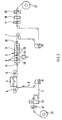
- FIG. 1 is schematically outlined a device with which a metal strand 1 is first descaled and then hot-dip galvanized.
- the metal strand 1 enters the system at a predetermined conveying speed v in the conveying direction R and is initially guided between two S-roll stands 5 and 6, which exert a tensile force F on the metal strand 1.
- a means 4 for straightening the metal strand 1 is arranged. This means 4 is a stretch bending straightening machine.
- the metal strand 1 in the stretch bending straightening machine 4 is bent or set by adjustable rollers under high tension by the tensile force F so that the metal strand 1 has a high degree of flatness after leaving the stretch bending straightening machine 4 Has.
- the metal strand 1 is fed to the device 2 for plasma descaling or cleaning.
- This device 2 has a treatment chamber 8, which is kept under a vacuum.
- a respective lock 19 and 20 is provided at the inlet or outlet of the metal strand 1 into or out of the treatment chamber 8.
- an S-roller stand 7 is also arranged; in cooperation with the S-roller stand 6, it is thus possible to keep the metal strand 1 in pulling the device 2 under train (tensile force F), so that in synergy with the stretch bending straightening machine 4 ensures that the metal strand 1, the device. 2 goes through with an extremely high degree of flatness. This is necessary to achieve a good result of the descaling or cleaning.
- a number of electrodes 9 are arranged, which are required to generate the plasma, with which the surface of the metal strand 1 is descaled or cleaned. Details can be found in the aforementioned literature.
- FIG. 1 In conveying direction R are - like it FIG. 1 can be removed - several electrodes 9 arranged one behind the other. These can all be activated simultaneously for descaling or cleaning, d. h be supplied with electrical energy. However, it is also possible to selectively switch the individual module-shaped electrodes 9 in such a way that only a number of electrodes is activated as required to achieve a desired descaling or cleaning result.
- a test means 10 is arranged, which is able to inspect the surface of the metal strand 1 and pass the result of the test to a control means 11.
- the control means 11 acts on the drive of the overall device, not shown, in such a way that the conveying speed v of the metal strand 1 is influenced such that the result of the descaling or cleaning of a desired specification equivalent.
- the control means 11 can reduce the conveying speed v; As a result, the surface of the metal strand 1 is exposed to a longer exposure time of the plasma, which improves the Entzu matters- or cleaning result. However, if there is already an excessively large, unneeded quality, the control means 11 can provide an increase in the conveying speed v, so that although the quality of the descaling or cleaning is reduced, the productivity of the overall system is increased.
- FIG. 1 can be further removed, located in the conveying direction R behind the device 2 for plasma descaling or cleaning an induction heating 14, which can heat the metal strand 1.
- This may in particular be an inductively heated annealing furnace with a protective gas atmosphere, with which it is possible to heat the metal strand 1 to a temperature of about 500 ° C. in a very short time.
- the metal strand 1 is conducted under protective gas and via a proboscis, not shown, into a vessel 3 with liquid coating metal.
- a guide roller 13 is arranged, which deflects the metal strand 1 after coating with liquid coating metal vertically upwards.
- the induction heating means 14, the boiler 3 and the deflection roller 13 form the schematically illustrated means 12 for coating the metal strand 1.
- FIG. 2 An alternative embodiment of the system is in FIG. 2 to see.
- the difference to FIG. 1 is that in FIG. 2
- the device 2 for plasma descaling or cleaning means 15 for rolling the descaled or cleaned metal strand 1 are connected downstream. These means are a multi-stand cold rolling tandem mill on which the metal strand 1 is rolled to the desired final thickness.
- FIG. 3 an apparatus is sketched, which serves only the descaling of the metal strand 1, but in the manner of the in the FIGS. 1 and 2 shown solutions can also be combined with subsequent facilities.
- the metal strand 1 is fed in wound form from a reel 21 of a welding machine 22, where the metal strand 1 is welded together with the preceding metal strand. Before welding, the tape ends are cut with scissors 23 to allow a perfect weld.
- the metal strand 1 is then fed to the stretch straightening machine 4, in which the strand 1 can be directed by bending and applying a tensile force so that it has an optimum flatness, before it enters the device 2 for plasma descaling or plasma cleaning enters.
- the metal strand 1 passes through the lock 19, whereupon it is in the treatment chamber 8, in which there is a vacuum.
- the vacuum is generated by the vacuum pump 24.
- descaling or cleaning is carried out by the located between the electrodes 9 and the metal strand 1 plasma.
- the number of electrodes 9 depends on the belt speed v to ensure the required residence time of the metal strand 1 in the plasma.
- the exact width of the metal strand 1 is achieved. If necessary, the metal strand 1 is then electrostatically oiled with the oiling machine 18 to protect the surface of the metal strand 1 from corrosion. With a pair of scissors 26, the metal strand 1 is divided before pushing off the finished federal. It can also be used with two reels 21 and 27 be worked in the inlet and the outlet to achieve the shortest possible exchange times.
- Cold-rolled, oiled steel strip for example, has to pass through special alkaline and electrolytic cleaning tanks, followed by rinsing and sometimes also brushing, in front of a metallic coating in order to achieve the required metallically bright surface.
- Previous systems also use this chemical means in which pose the aforementioned environmental problems.
- the use of the plasma technology for the cleaning of the metal strand brings here also great advantages.
Landscapes
- Chemical & Material Sciences (AREA)
- Mechanical Engineering (AREA)
- Engineering & Computer Science (AREA)
- Organic Chemistry (AREA)
- Chemical Kinetics & Catalysis (AREA)
- Materials Engineering (AREA)
- Metallurgy (AREA)
- Optics & Photonics (AREA)
- Physics & Mathematics (AREA)
- General Chemical & Material Sciences (AREA)
- Cleaning And De-Greasing Of Metallic Materials By Chemical Methods (AREA)
- Metal Rolling (AREA)
- Coating With Molten Metal (AREA)
- Cleaning In General (AREA)
- Heat Treatment Of Strip Materials And Filament Materials (AREA)
- Arc Welding In General (AREA)
- Physical Vapour Deposition (AREA)
- Exhaust Gas Treatment By Means Of Catalyst (AREA)
- Catalysts (AREA)
Description
- Die Erfindung betrifft ein Verfahren zum Entzundern und/oder Reinigen eines Metallstrangs, insbesondere eines warmgewalzten Bandes aus Normalstahl oder aus nicht rostendem Stahl, bei dem der Metallstrang in eine Förderrichtung durch eine Vorrichtung geführt wird, in der er einer Plasma-Entzunderung und/oder einer Plasma-Reinigung unterzogen wird. Des weiteren betrifft die Erfindung eine Vorrichtung zum Entzundern und/oder Reinigen eines derartigen Metallstrangs.
- Ein Verfahren der gattungsgemäßen Art ist aus der
JP 03207518 A - Für die Weiterverarbeitung - z. B. durch Kaltwalzen, für eine metallische Beschichtung oder die direkte Verarbeitung zu einem Endprodukt - muss warmgewalztes Stahlband eine zunderfreie Oberfläche haben. Daher muss der beim Warmwalzen und während der nachfolgenden Abkühlung entstandene Zunder restlos entfernt werden. Dies erfolgt bei vorbekannten Verfahren durch einen Beizprozess, wobei der aus den verschiedenen Eisenoxiden (FeO, Fe3O4, Fe2O3) oder bei nichtrostenden Stählen auch aus chromreichen Eisenoxiden bestehende Zunder je nach Stahlqualität mittels verschiedener Säuren (z.B. Salzsäure, Schwefelsäure, Salpetersäure oder Mischsäure) bei erhöhten Temperaturen durch chemische Reaktion mit der Säure gelöst wird. Vor dem Beizen ist bei Normalstahl noch eine zusätzliche mechanische Behandlung durch Streckbiegerichten erforderlich, um den Zunder aufzubrechen und somit ein schnelleres Eindringen der Säure in die Zunderschicht zu ermöglichen. Bei den wesentlich schwieriger zu beizenden nichtrostenden, austenitischen und ferritischen Stählen sind ein Glühen und eine mechanische Vorentzunderung des Bandes beim Beizprozess vorgeschaltet, um eine möglichst gut beizbare Bandoberfläche zu erzielen. Nach dem Beizen muss das Stahlband gespült, getrocknet und je nach Bedarf eingeölt werden, um eine Oxidation zu verhindern.
- Das Beizen von Stahlband wird in kontinuierlichen Linien durchgeführt, deren Prozessteil in Abhängigkeit von der Bandgeschwindigkeit eine sehr große Länge haben kann. Derartige Anlagen erfordern daher sehr hohe Investitionen. Der Beizprozess erfordert außerdem sehr viel Energie und einen hohen Aufwand für die Entsorgung der Abwässer und die Regenerierung der Salzsäure, die bei Normalstahl meistens verwendet wird.
- Es gibt daher im Stand der Technik verschiedenartige Ansätze, die Entzunderung von metallischen Strängen ohne Einsatz von Säuren zu bewerkstelligen. Bisher bekannte Entwicklungen basieren hier zumeist auf einer mechanischen Entfernung des Zunders (z. B. Ishiclean-Verfahren, APO-Verfahren). Allerdings sind derartige Verfahren hinsichtlich ihrer Wirtschaftlichkeit und Qualität der entzunderten Oberfläche für die industrielle Entzunderung von breitem Stahlband nicht geeignet. Daher wird bei der Entzunderung derartigen Bandes nach wie vor auf den Einsatz von Säuren gesetzt.
- Die Nachteile hinsichtlich der Wirtschaftlichkeit und der Umweltbelastung müssen daher bislang in Kauf genommen werden.
- Neuere Ansätze für das Entzundern von metallischen Strängen setzen auf die Plasma-Technologie. Dieses Verfahren ist in der bereits eingangs genannten
JP 03207518 A WO 00/56949 A1 WO 01/00337 A1 RU 2153025 C1 RU 2139151 C1 - Der genannte Stand der Technik stellt dabei primär auf die Entzunderung von Draht und von Rohren ab. Hierbei ergibt sich der Vorteil, dass aufgrund der Geometrie des zu entzundemden Gutes eine relativ einfache Führung der Elektroden möglich ist, so dass die Entzunderung effizient erfolgen kann.
- Bei der Entzunderung von Stahlband hat es sich jedoch gezeigt, dass das in den genannten Schriften offenbarte Verfahren zu keinem brauchbaren Ergebnis führt, d. h. dass das entsprechend behandelte Stahlband, zumindest wenn es eine gewisse Breite aufweist, nicht in der benötigten Qualität entzundert werden kann.
- Zwar offenbart die
JP 07 275920 A - Der Erfindung liegt daher die Aufgabe zugrunde, ein Verfahren und eine zugehörige Vorrichtung zum Entzundern und/oder zum Reinigen eines Metallstrangs zu schaffen, mit dem bzw. mit der es möglich ist, auch breite Metallstränge über ihre gesamte Breitenerstreckung in gleichbleibender Qualität effizient und wirkungsvoll mittels der Plasma-Technologie zu entzundern, wobei sowohl die ökonomischen als auch die ökologischen Vorteile dieses Verfahrens nutzbar sein sollen.
- Diese Aufgabe wird durch die Erfindung verfahrensgemäß dadurch gelöst, dass der Metallstrang in Förderrichtung vor der Vorrichtung zur Plasma-Entzunderung und/oder Plasma-Reinigung einem Streck-Richtprozess oder einem Streckbiege-Richtprozess unterzogen wird, der dem Metallstrang einen hohen Planheits-Grad verleiht.
- Mit diesem Prozess kann auf den Metallstrang nämlich eine Zugkraft ausgeübt werden, die eine solche Höhe hat, dass die Planheit des in die Vorrichtung zur Plasma-Entzunderung und/oder Plasma-Reinigung einlaufenden Metallstrangs so hoch ist, dass der Strang die Vorrichtung als ebenes Blech durchlaufen kann. Das Resultat der Entzunderung bzw. Reinigung wird dadurch wesentlich verbessert, so dass das gefertigte Metallband eine hohe Qualität aufweist.
- Es hat sich als vorteilhaft herausgestellt, dass die Zugkraft beim Richtprozess so gewählt wird, dass im Metallstrang eine Zugspannung auftritt, die mindestens 10 % der Streckgrenze des Materials des Metallstrangs entspricht.
- Das Verfahren kann bei kontinuierlich durchlaufendem Metallstrang betrieben werden; es ist aber auch genauso möglich, den Strang diskontinuierlich, also mit nicht konstanter Geschwindigkeit, durch die Entzunderungs- bzw. Reinigungsanlage zu führen. Der zuletzt genannte Fall ist vor allem für kleine Anlagen interessant.
- Eine besonders hohe Qualität des gefertigten Metallstrangs kann erreicht werden, wenn nach der Vorrichtung zur Plasma-Entzunderung und/oder Plasma-Reinigung eine Prüfung der Oberfläche des Metallstrangs durchgeführt wird; es ist dann vorgesehen, dass die Geschwindigkeit, mit der der Metallstrang durch die Vorrichtung zur Plasma-Entzunderung und/oder Plasma-Reinigung geführt wird, in Abhängigkeit von der Prüfung im geschlossenen Regelkreis so vorgegeben wird, dass eine gewünschte Entzunderungsqualität bzw. Reinigungsqualität erzielt wird. Dies bedeutet, dass namentlich bei noch ungenügender Entzunderungsqualität bzw. Reinigungsqualität die Durchlaufgeschwindigkeit des Metallstrangs durch die Vorrichtung zur Plasma-Entzunderung und/oder Plasma-Reinigung herabgesetzt wird, so dass das Plasma eine längere Einwirkungszeit auf den Metallstang hat. Dadurch lässt sich die Qualität des Entzunderungs- bzw. Reinigungsvorgangs an die speziellen Bedürfnisse anpassen.
- Besonders bevorzugt kann sich direkt an das Entzundern und/oder Reinigen des Metallstrangs eine Beschichtung des Strangs mit flüssigem Metall anschließen, insbesondere eine Feuerverzinkung. Hierfür finden die bekannten Beschichtungsverfahren Anwendung. Eine Möglichkeit besteht darin, den Metallstrang durch einen Kessel, der mit dem flüssigen Beschichtungsmetall gefüllt ist, zu führen, wobei eine Umlenkung des Metallstrangs im Kessel stattfindet. Alternativ kann aber auch das CVGL-Verfahren (Continuous Vertical Galvanizing Line) zum Einsatz kommen, bei dem der Metallstrang durch einen Kessel, der mit dem flüssigen Metall gefüllt ist, von unten hindurchgeführt wird, wobei das Beschichtungsmetall im Kessel durch einen elektromagnetischen Verschluss zurückgehalten wird. Nach dem Entzundern und/oder Reinigen und vor dem Beschichten mit flüssigem Metall erfolgt bevorzugt eine Erwärmung des Metallstangs, vorzugsweise durch Induktionserwärmung.
- Im unmittelbaren Anschluss an das Entzundern und/oder Reinigen des Metallstrangs kann vorteilhaft ein Kaltwalzen des Metallstrangs erfolgen.
- Die Vorrichtung zum Entzundern und/oder Reinigen des Metallstrangs weist eine Anordnung auf, durch die der Metallstrang in Förderrichtung geführt wird und in der der Metallstrang einer Plasma-Entzunderung und/oder einer Plasma-Reinigung unterzogen wird. Die Vorrichtung ist erfindungsgemäß gekennzeichnet durch Mittel, mit denen dem Metallstrang in Förderrichtung vor der Anordnung zur Plasma-Entzunderung und/oder Plasma-Reinigung ein hoher Planheits-Grad verliehen werden kann, wobei vor und/oder hinter dem Mittel mindestens eine Spannvorrichtung zur Erzeugung einer Zugkraft im Metallstrang angeordnet ist. Diese Mittel bestehen aus mindestens einer Streckricht- oder Streckbiegericht-Maschine. Als Spannvorrichtung hat sich der S-Rollenstand bewährt.
- Eine besonders gute Führung des Metallstrangs durch die Vorrichtung zur Plasma-Entzunderung und/oder Plasma-Reinigung kann erreicht werden, wenn in Förderrichtung hinter der Vorrichtung zur Plasma-Entzunderung und/oder Plasma-Reinigung eine Spannvorrichtung zur Erzeugung einer Zugkraft im Metallstrang angeordnet ist, wobei auch hier bevorzugt an einen S-Rollenstand gedacht ist. Dadurch wird der Metallstrang beim Passieren der Plasma-Vorrichtung sehr eben gehalten, was die Qualität der Entzunderung bzw. Reinigung erhöht.
- Die Vorrichtung zur Plasma-Entzunderung und/oder Plasma-Reinigung kann eine unter Vakuum stehende Behandlungskammer aufweisen, in der in Förderrichtung des Metallstrangs eine Anzahl modulartig aufgebauter Elektroden angeordnet sind. Dabei kann vorgesehen werden, dass die einzelnen Elektroden in Abhängigkeit vom Grad der Verzunderung und/oder dem Grad der Verschmutzung der Oberfläche des Metallstrangs sowie in Abhängigkeit von der Geschwindigkeit, mit der der Metallstrang die Plasma-Vorrichtung passiert, unabhängig voneinander ein- und abgeschaltet werden. Es können namentlich genau so viele Elektroden bei der Entzunderung bzw. Reinigung eingeschaltet werden, dass ein gewünschtes Ergebnis erreicht wird.
- Eine weitere Qualitätsverbesserung der Entzunderung bzw. Reinigung kann erreicht werden, wenn in Förderrichtung hinter der Vorrichtung zur Plasma-Entzunderung und/oder Plasma-Reinigung Prüfmittel zur Prüfung der Oberfläche des Metallstrangs angeordnet werden; diese stehen dann mit Regelmitteln in Verbindung, wobei diese Regelmittel die Geschwindigkeit, mit der der Metallstrang durch die Vorrichtung geführt wird, in Abhängigkeit von der Prüfung so vorgeben, dass eine gewünschte Entzunderungsqualität bzw. Reinigungsqualität des Metallstrangs erzielt wird.
- Mit Vorteil wird - wie bereits ausgeführt - die erfindungsgemäße Entzunderungs- bzw. Reinigungsanlage in Kombination mit weiteren Behandlungseinrichtungen für den Metallstrang eingesetzt. In Förderrichtung hinter der Vorrichtung zur Plasma-Entzunderung und/oder Plasma-Reinigung können dabei Mittel zum Beschichtung des Metallstrangs mit flüssigem Metall, insbesondere zum Feuerverzinken, angeordnet werden. Diese Mittel können einen Kessel für flüssiges Metall und mindestens eine in diesen integrierte Umlenkrolle aufweisen. Alternativ können die Mittel zum Beschichtung einen Kessel für flüssiges Metall und unter dem Kessel elektromagnetische Mittel zum Zurückhalten des flüssigen Metalls im Kessel aufweisen. In Förderrichtung hinter der Vorrichtung zur Plasma-Entzunderung und/oder Plasma-Reinigung und in Förderrichtung vor den Mitteln zum Beschichtung des Metallstrangs können Mittel zum Erwärmen des Metallstrangs, insbesondere Induktionsheizmittel, angeordnet sein.
- Alternativ oder additiv zu den Beschichtungsmitteln können in Förderrichtung hinter der Vorrichtung zur Plasma-Entzunderung und/oder Plasma-Reinigung Mittel zum Walzen des Metallstrangs angeordnet werden; bei diesen kann es sich um eine mehrgerüstige Kaltwalz-Tandemstrasse handeln.
- Ein kontinuierlicher Betrieb der gesamten Anlage wird dadurch begünstigt, dass in Förderrichtung vor der Vorrichtung zur Plasma-Entzunderung und/oder Plasma-Reinigung ein Bandspeicher angeordnet wird.
- Vorteilhaft für eine hohe Produktivität der Anlage ist es weiterhin, wenn in Förderrichtung hinter der Vorrichtung zur Plasma-Entzunderung und/oder Plasma-Reinigung Mittel zum Besäumen des Metallstrangs (Besäumschere) angeordnet sind.
- Die Produktivität der Anlage wird weiterhin auch dadurch verbessert, dass in Förderrichtung hinter der Vorrichtung zur Plasma-Entzunderung und/oder Plasma-Reinigung Mittel zum Einölen des Metallstrangs angeordnet werden.
- Insgesamt ergibt sich eine hochproduktive Anlage zur Verarbeitung eines Metallstrangs, bevorzugt für warmgewalztes Band aus Normalstahl oder aus nicht rostendem Stahl, die eine ökonomische und ökologische Entzunderung und/oder Reinigung des Metallstrangs sicherstellen kann und die sich vor allem in der Kombination mit nachgeschalteten Behandlungseinrichtungen bewährt hat.
- Die beschriebene Technologie bietet vor allem im Vergleich mit dem Beizen große Vorteile hinsichtlich des Umweltschutzes, dem Energieverbrauch und der Qualität. Ferner sind die Investitionskosten für entsprechende Anlagen wesentlich geringer als bei bekannten Entzunderungs- und/oder Reinigungsanlagen.
- In der Zeichnung sind Ausführungsbeispiele der Erfindung dargestellt. Es zeigen:
- Fig. 1
- schematisch eine Vorrichtung zur Entzunderung und nachfolgenden Feuerverzinkung eines Metallstrangs,
- Fig. 2
- schematisch eine Vorrichtung zur Entzunderung und zum nachfolgenden Walzen des Metallstrangs und
- Fig. 3
- schematisch eine Vorrichtung zur Entzunderung des Metallstrangs.
- In
Figur 1 ist schematisch eine Vorrichtung skizziert, mit der ein Metallstrang 1 zunächst entzundert und anschließend feuerverzinkt werden kann. Der Metallstrang 1 tritt mit vorgegebener Fördergeschwindigkeit v in Förderrichtung R in die Anlage ein und wird zunächst zwischen zwei S-Rollenständen 5 und 6 geführt, die auf den Metallstrang 1 eine Zugkraft F ausüben. Zwischen den beiden S-Rollenständen 5, 6 ist ein Mittel 4 zum Richten des Metallstrangs 1 angeordnet. Es handelt sich bei diesem Mittel 4 um eine Streckbiege-Richtmaschine. Schematisch ist angedeutet, dass der Metallstrang 1 in der Streckbiege-Richtmaschine 4 durch anstellbare Walzen unter hoher Spannung durch die Zugkraft F so gebogen bzw. gerichtet wird, dass der Metallstrang 1 einen hohen Planheits-Grad aufweist, nachdem er die Streckbiege-Richtmaschine 4 verlassen hat. - Im Anschluss an die Streckbiege-Richtmaschine 4 wird der Metallstrang 1 der Vorrichtung 2 zur Plasma-Entzunderung bzw. -Reinigung zugeführt. Diese Vorrichtung 2 weist eine Behandlungskammer 8 auf, die unter einem Vakuum gehalten wird. Am Ein- bzw. Austritt des Metallstrangs 1 in die bzw. aus der Behandlungskammer 8 ist je eine Schleuse 19 bzw. 20 vorgesehen.
- In Förderrichtung hinter der Vorrichtung 2 ist ebenfalls ein S-Rollenstand 7 angeordnet; im Zusammenwirken mit dem S-Rollenstand 6 ist es somit möglich, den Metallstrang 1 beim Passieren der Vorrichtung 2 unter Zug zu halten (Zugkraft F), so dass in Synergie mit der Streckbiege-Richtmaschine 4 sichergestellt ist, dass der Metallstrang 1 die Vorrichtung 2 mit einem extrem hohen Grad an Planheit durchläuft. Diese ist zur Erzielung eines guten Ergebnisses der Entzunderung bzw. Reinigung erforderlich.
- Wie in
Figur 1 gesehen werden kann, sind in der Behandlungskammer 8 eine Anzahl Elektroden 9 angeordnet, die erforderlich sind, um das Plasma zu erzeugen, mit dem die Oberfläche des Metallstrangs 1 entzundert bzw. gereinigt wird. Details hierzu sind im vorgenannten Schrifttum zu finden. - In Förderrichtung R sind - wie es
Figur 1 entnommen werden kann - mehrere Elektroden 9 hintereinander angeordnet. Diese können alle gleichzeitig zum Entzundern bzw. Reinigen aktiviert, d. h mit elektrischer Energie versorgt werden. Es ist jedoch auch möglich, die einzelnen modulartig ausgebildeten Elektroden 9 wahlweise so zu schalten, dass nur eine solche Anzahl Elektroden aktiviert wird, wie es zur Erzielung eines gewünschten Entzunderungs- bzw. Reinigungsergebnisses erforderlich ist. - In Förderrichtung R hinter der Vorrichtung 2 zur Plasma-Entzunderung bzw. - Reinigung ist ein Prüfmittel 10 angeordnet, das in der Lage ist, die Oberfläche des Metallstrangs 1 zu inspizieren und das Ergebnis der Prüfung an ein Regelmittel 11 weiterzugeben. Abhängig von der gewünschten Qualität der Entzunderung bzw. Reinigung kann vorgesehen werden, dass das Regelmittel 11 auf den nicht dargestellten Antrieb der Gesamtvorrichtung derart einwirkt, dass die Fördergeschwindigkeit v des Metallstrangs 1 so beeinflusst wird, dass das Ergebnis der Entzunderung bzw. Reinigung einer gewünschten Vorgabe entspricht.
- Reicht die Qualität der Entzunderung bzw. Reinigung nicht aus, können die Regelmittel 11 die Fördergeschwindigkeit v herabsetzen; dadurch ist die Oberfläche des Metallstrangs 1 einer längeren Einwirkzeit des Plasmas ausgesetzt, wodurch sich das Entzunderungs- bzw. Reinigungsergebnis verbessert. Liegt indes bereits eine übermäßig große, nicht benötigte Qualität vor, können die Regelmittel 11 eine Erhöhung der Fördergeschwindigkeit v vorsehen, so dass die Qualität der Entzunderung bzw. Reinigung zwar herabgesetzt, die Produktivität der Gesamtanlage jedoch erhöht wird.
- Wie
Figur 1 weiter entnommen werden kann, befindet sich in Förderrichtung R hinter der Vorrichtung 2 zur Plasma-Entzunderung bzw. -Reinigung ein Induktionsheizmittel 14, das den Metallstrang 1 erwärmen kann. Es kann sich hierbei insbesondere um einen induktiv beheizten Glühofen mit einer SchutzgasAtmosphäre handeln, mit es möglich ist, in sehr kurzer Zeit den Metallstrang 1 auf eine Temperatur von etwa 500 °C zu erhitzen. Anschließend wird der Metallstrang 1 unter Schutzgas und über einen nicht dargestellten Rüssel in einen Kessel 3 mit flüssigem Beschichtungsmetall geführt. Im Kessel 3 ist eine Umlenkrolle 13 angeordnet, die den Metallstrang 1 nach der Beschichtung mit flüssigem Beschichtungsmetall vertikal nach oben umlenkt. Die Induktionsheizmittel 14, der Kessel 3 und die Umlenkrolle 13 bilden die schematisch dargestellten Mittel 12 zum Beschichten des Metallstrangs 1. - Eine alternative Ausgestaltung der Anlage ist in
Figur 2 zu sehen. Der Unterschied zuFigur 1 besteht darin, dass inFigur 2 der Vorrichtung 2 zur Plasma-Entzunderung bzw. -Reinigung Mittel 15 zum Walzen des entzunderten bzw. gereinigten Metallstrangs 1 nachgeschaltet sind. Bei diesen Mitteln handelt es sich um eine mehrgerüstige Kaltwalz-Tandemstraße, auf der der Metallstrang 1 auf die gewünschte Enddicke gewalzt wird. - In
Figur 3 ist eine Vorrichtung skizziert, die lediglich der Entzunderung des Metallstrangs 1 dient, die jedoch nach Art der in denFiguren 1 und2 gezeigten Lösungen auch mit nachfolgenden Einrichtungen kombiniert werden kann. - Der Metallstrang 1 wird in aufgewickelter Form von einem Abhaspel 21 einer Schweißmaschine 22 zugeführt, wo der Metallstrang 1 mit dem vorhergehenden Metallstrang zusammengeschweißt wird. Vor dem Schweißen werden die Bandenden mit einer Schere 23 geschnitten, um eine einwandfreie Schweißung zu ermöglichen.
- Der Metallstrang 1 wird dann der Streck-Richtmaschine bzw. Streckbiege-Richtmaschine 4 zugeführt, in der der Strang 1 durch Biegung und Aufbringung einer Zugkraft so gerichtet werden kann, dass er eine optimale Planheit hat, bevor er in die Vorrichtung 2 zur Plasma-Entzunderung bzw. Plasma-Reinigung einläuft. Zunächst durchtritt der Metallstrang 1 die Schleuse 19, woraufhin er sich in der Behandlungskammer 8 befindet, in der ein Vakuum herrscht. Das Vakuum wird durch die Vakuumpumpe 24 erzeugt. In der Behandlungskammer 8 erfolgt die Entzunderung bzw. Reinigung durch das sich zwischen den Elektroden 9 und dem Metallstrang 1 befindliche Plasma. Die Zahl der Elektroden 9 hängt dabei von der Bandgeschwindigkeit v ab, um die erforderliche Verweilzeit des Metallstrangs 1 im Plasma zu gewährleisten.
- Nach der vollständigen Entzunderung bzw. hinreichenden Reinigung läuft der Metallstrang 1 durch die Vakuumschleuse 20 zum S-Rollenstand 7, der - wie bereits erläutert - den erforderlichen hohen Bandzug für einen möglichst horizontalen Banddurchlauf im Zusammenwirken mit dem S-Rollenstand 6 erzeugt. Bei längeren Behandlungskammern 8 und für hohe Bandgeschwindigkeiten v sind Tragrollen 25 zwischen den Elektroden 9 angeordnet, die einen Durchhang des Metallstrangs 1 verhindern.
- Mit der Besäumschere 17 wird die genaue Breite des Metallstrangs 1 erzielt. Falls erforderlich, wird der Metallstrang 1 anschließend mit der Einölmaschine 18 elektrostatisch eingeölt, um die Oberfläche des Metallstrangs 1 vor Korrosion zu schützen. Mit einer Schere 26 wird der Metallstrang 1 vor dem Abschieben des fertigen Bundes zerteilt. Es kann auch mit je zwei Haspeln 21 und 27 im Einlauf und im Auslauf gearbeitet werden, um möglichst kurze Bundwechselzeiten zu erreichen.
- Mit einem Bandspeicher 16 und einem Bandspeicher 28 ist ein kontinuierlicher Bandlauf im Prozessteil der Anlage möglich. Für Anlagen mit geringer Leistung ist ein diskontinuierlicher Betrieb ohne Bandspeicher möglich, wobei die Anlage während der Bundwechsel angehalten wird. Im Gegensatz zum Beizen ist dies bei der Plasma-Entzunderung ohne Ausbringverluste möglich.
- In obiger Beschreibung wurde stets sowohl von der Entzunderung als auch von der Reinigung des Metallstrangs gesprochen. Es hat sich nämlich herausgestellt, dass die Plasma-Technologie nicht nur für die Entzunderung, sondern auch sehr gut für die Reinigung metallischer Oberflächen von organischen oder anorganischen Substanzen (z. B. Öl) geeignet ist.
- Kaltgewalztes geöltes Stahlband muss beispielsweise vor einer metallischen Beschichtung spezielle alkalische und elektrolytische Reinigungstanks mit nachfolgendem Spülen und teilweise auch Bürsten durchlaufen, um die erforderliche metallisch blanke Oberfläche zu erzielen. Vorbekannte Anlagen setzen auch hierfür chemische Mittel ein, bei denen sich die eingangs genannten Umweltprobleme stellen. Der Einsatz der Plasma-Technologie für die Reinigung des Metallstrangs bringt auch hier große Vorteile.
- Bei der Koppelung der in
Figur 3 skizzierten Anlage mit Nachfolgebehandlungseinrichtungen gemäß derFiguren 1 und2 ergeben sich - wie bereits erwähnt - hohe wirtschaftliche Vorteile. Die Zwischenlagerung des entzunderten bzw. gereinigten Bandes entfällt, so dass sowohl Produktions- als auch Qualitätsverbesserungen erzielt werden können. Dem Bandspeicher 28 (sieheFigur 3 ) hinter der Vorrichtung 2 zur Plasma-Entzunderung bzw. -Reinigung kommt dabei eine besondere Bedeutung zu. Das entzunderte und vorzugsweise bereits besäumte Band kann dann ohne Zwischenlagerung unter gleichmäßigem Bandzug kontinuierlich in die Nachfolgeeinrichtung (Feuerverzinkungsanlage, Kaltwalz-Tandemstraße) einlaufen. Das fertige Band kann dabei hinter der Nachfolgeeinrichtung, insbesondere hinter der Kaltwalz-Tandemstraße, wechselweise mit zwei Haspeln aufgewickelt und mit einer Schere unterteilt werden. -
- 1
- Metallstrang
- 2
- Vorrichtung zur Plasma-Entzunderung/-Reinigung
- 3
- Kessel mit flüssigem Beschichtungsmetall
- 4
- Mittel zum Richten des Metallstrangs (Streckrichtmaschine, Streckbiegerichtmaschine)
- 5
- Spannvorrichtung (S-Rollenstand)
- 6
- Spannvorrichtung (S-Rollenstand)
- 7
- Spannvorrichtung (S-Rollenstand)
- 8
- Behandlungskammer
- 9
- Elektroden
- 10
- Prüfmittel
- 11
- Regelmittel
- 12
- Mittel zum Beschichtung des Metallstrangs
- 13
- Umlenkrolle
- 14
- Mittel zum Erwärmen des Metallstrangs (Induktionsheizmittel)
- 15
- Mittel zum Walzen des Metallstrangs
- 16
- Bandspeicher
- 17
- Mittel zum Besäumen des Metallstrangs (Besäumschere)
- 18
- Mittel zum Einölen des Metallstrangs (Einölmaschine)
- 19
- Schleuse
- 20
- Schleuse
- 21
- Abhaspel
- 22
- Schweißmaschine
- 23
- Schere
- 24
- Vakuumpumpe
- 25
- Tragrolle
- 26
- Schere
- 27
- Aufhaspel
- 28
- Bandspeicher
- R
- Förderrichtung
- v
- Fördergeschwindigkeit
- F
- Zugkraft
Claims (14)
- Verfahren zum Entzundern und/oder Reinigen eines Metallstrangs (1), insbesondere eines warmgewalzten Bandes aus Normalstahl oder aus nicht rostendem Stahl, bei dem der Metallstrang (1) in Förderrichtung (R) durch eine Vorrichtung (2) geführt wird, in der er einer Plasma-Entzunderung und/oder einer Plasma-Reinigung unterzogen wird,
dadurch gekennzeichnet,
dass der Metallstrang (1) in Förderrichtung (R) vor der Vorrichtung (2) zur Plasma-Entzunderung und/oder Plasma-Reinigung einem Streck-Richtprozess oder einem Streckbiege-Richtprozess unterzogen wird, der dem Metallstrang (1) einen hohen Planheits-Grad verleiht. - Verfahren nach Anspruch 1,
dadurch gekennzeichnet,
dass eine Zugkraft (F) so ausgeübt wird, dass im Metallstrang (1) eine Zugspannung auftritt, die mindestens 10 % der Streckgrenze des Materials des Metallstrangs (1) entspricht. - Verfahren nach Anspruch 1 oder 2,
dadurch gekennzeichnet
dass der Metallstrang (1) kontinuierlich durch die Vorrichtung (2) zur Plasma-Entzunderung und/oder Plasma-Reinigung geführt wird. - Verfahren nach Anspruch 1 oder 2,
dadurch gekennzeichnet,
dass der Metallstrang (1) diskontinuierlich durch die Vorrichtung (2) zur Plasma-Entzunderung und/oder Plasma-Reinigung geführt wird. - Verfahren nach einem der Ansprüche 1 bis 4,
dadurch gekennzeichnet,
dass nach der Vorrichtung (2) zur Plasma-Entzunderung und/oder Plasma-Reinigung eine Prüfung der Oberfläche des Metallstrangs (1) durchgeführt wird, wobei die Geschwindigkeit (v), mit der der Metallstrang (1) durch die Vorrichtung (2) zur Plasma-Entzunderung und/oder Plasma-Reinigung geführt wird, in Abhängigkeit von der Prüfung im geschlossenen Regelkreis so vorgegeben wird, dass eine gewünschte Entzunderungsqualität bzw. Reinigungsqualität erzielt wird. - Verfahren nach einem der Ansprüche 1 bis 5,
dadurch gekennzeichnet,
dass der Metallstrang (1) im Anschluss an das Entzundern und/oder Reinigen des mit flüssigem Metall beschichtet wird, insbesondere in einer Feuerverzinkung. - Verfahren nach Anspruch 6,
dadurch gekennzeichnet,
dass der Metallstrang (1) nach dem Entzundern und/oder Reinigen und vor dem Beschichten mit flüssigem Metall einer Erwärmung, insbesondere einer Induktionserwärmung, unterzogen wird. - Verfahren nach einem der Ansprüche 1 bis 7,
dadurch gekennzeichnet,
dass der Metallstrang (1) im Anschluss an das Entzundern und/oder Reinigen kaltgewalzt wird. - Vorrichtung zum Entzundern und/oder Reinigen eines Metallstrangs (1), insbesondere eines warmgewalzten Bandes aus Normalstahl oder aus nicht rostendem Stahl, insbesondere zur Durchführung des Verfahrens nach einem der Ansprüche 1 bis 8, die eine Vorrichtung (2) aufweist, durch die der Metallstrang (1) in eine Förderrichtung (R) geführt wird und in der der Metallstrang (1) einer Plasma-Entzunderung und/oder einer Plasma-Reinigung unterzogen wird,
gekennzeichnet durch
Mittel (4), die in Förderrichtung (R) vor der Vorrichtung (2) zur Plasma-Entzunderung und/oder Plasma-Reinigung angeordnet sind und dem Metallstrang (1) einen hohen Planheits-Grad verleihen, wobei vor und/oder hinter dem Mittel (4) mindestens eine Spannvorrichtung (5, 6) zur Erzeugung einer Zugkraft (F) im Metallstrang (1) angeordnet ist. - Vorrichtung nach Anspruch 9,
dadurch gekennzeichnet,
dass die Vorrichtung (2) zur Plasma-Entzunderung und/oder Plasma-Reinigung eine unter Vakuum stehende Behandlungskammer (8) aufweist, in der in Förderrichtung (R) des Metallstrangs (1) eine Anzahl modulartig aufgebauter Elektroden (9) angeordnet sind. - Vorrichtung nach Anspruch 10,
dadurch gekennzeichnet,
dass die einzelnen Elektroden (9) in Abhängigkeit vom Grad der Verzunderung und/oder dem Grad der Verschmutzung der Oberfläche des Metallstrangs (1) sowie in Abhängigkeit von der Geschwindigkeit (v), mit der der Metallstrang (1) die Vorrichtung (2) zur Plasma-Entzunderung und/oder Plasma-Reinigung passiert, unabhängig voneinander ein- und abschaltbar sind. - Vorrichtung nach einem der Ansprüche 9 bis 11,
dadurch gekennzeichnet,
dass in Förderrichtung (R) hinter der Vorrichtung (2) zur Plasma-Entzunderung und/oder Plasma-Reinigung Prüfmittel (10) zur Prüfung der Oberfläche des Metallstrangs (1) angeordnet sind, die mit Regelmitteln (11) in Verbindung stehen, wobei die Regelmittel (11) die Geschwindigkeit (v), mit der der Metallstrang (1) durch die Vorrichtung (2) zur Plasma-Entzunderung und/oder Plasma-Reinigung geführt wird, in Abhängigkeit von der Prüfung zur Erzielung der gewünschten Entzunderungsqualität bzw. Reinigungsqualität des Metallstrangs (1) vorgeben. - Vorrichtung nach einem der Ansprüche 9 bis 12,
dadurch gekennzeichnet,
dass in Förderrichtung (R) hinter der Vorrichtung (2) zur Plasma-Entzunderung und/oder Plasma-Reinigung Mittel (12) zum Beschichten des Metallstrangs (1) mit flüssigem Metall, insbesondere zum Feuerverzinken, angeordnet sind. - Vorrichtung nach einem der Ansprüche 9 bis 13,
dadurch gekennzeichnet,
dass in Förderrichtung (R) hinter der Vorrichtung (2) zur Plasma-Entzunderung und/oder Plasma-Reinigung Mittel (15) zum Kaltwalzen des Metallstrangs (1) angeordnet sind.
Applications Claiming Priority (3)
| Application Number | Priority Date | Filing Date | Title |
|---|---|---|---|
| DE10252178A DE10252178A1 (de) | 2002-11-09 | 2002-11-09 | Verfahren und Vorrichtung zum Entzundern und/oder Reinigen eines Metallstrangs |
| DE10252178 | 2002-11-09 | ||
| PCT/EP2003/010852 WO2004044257A1 (de) | 2002-11-09 | 2003-09-30 | Verfahren und vorrichtung zum entzundern und/oder reinigen eines metallstrangs |
Publications (2)
| Publication Number | Publication Date |
|---|---|
| EP1558779A1 EP1558779A1 (de) | 2005-08-03 |
| EP1558779B1 true EP1558779B1 (de) | 2008-12-31 |
Family
ID=32185405
Family Applications (1)
| Application Number | Title | Priority Date | Filing Date |
|---|---|---|---|
| EP03753485A Revoked EP1558779B1 (de) | 2002-11-09 | 2003-09-30 | Verfahren und vorrichtung zum entzundern und/oder reinigen eines metallstrangs |
Country Status (17)
| Country | Link |
|---|---|
| US (1) | US20060108034A1 (de) |
| EP (1) | EP1558779B1 (de) |
| JP (1) | JP4431045B2 (de) |
| KR (1) | KR101010580B1 (de) |
| CN (1) | CN100471981C (de) |
| AT (1) | ATE419407T1 (de) |
| AU (1) | AU2003271666B2 (de) |
| BR (1) | BR0315719A (de) |
| CA (1) | CA2505152C (de) |
| DE (2) | DE10252178A1 (de) |
| ES (1) | ES2316798T3 (de) |
| MX (1) | MXPA05004995A (de) |
| MY (1) | MY138080A (de) |
| PL (1) | PL207871B1 (de) |
| RU (1) | RU2325965C2 (de) |
| TW (1) | TWI316002B (de) |
| WO (1) | WO2004044257A1 (de) |
Cited By (1)
| Publication number | Priority date | Publication date | Assignee | Title |
|---|---|---|---|---|
| DE102020202722A1 (de) | 2020-03-03 | 2021-09-09 | Trumpf Laser- Und Systemtechnik Gmbh | Verfahren zum Bearbeiten eines Werkstücks und Bearbeitungssystem |
Families Citing this family (23)
| Publication number | Priority date | Publication date | Assignee | Title |
|---|---|---|---|---|
| DE102005012296A1 (de) † | 2005-03-17 | 2006-09-21 | Sms Demag Ag | Verfahren und Vorrichtung zum Entzundern eines Metallbandes |
| AT503377B1 (de) * | 2006-02-02 | 2008-09-15 | Eiselt Primoz | Verfahren und vorrichtung zur plasmabehandlung von materialien |
| KR101149087B1 (ko) * | 2007-06-27 | 2012-05-25 | 최원영 | 스테인레스스틸 코일의 표면가공장치 |
| RU2366759C2 (ru) * | 2007-11-12 | 2009-09-10 | Государственное образовательное учреждение высшего профессионального образования "Казанский государственный технологический университет" | Способ обработки металлокорда |
| RU2365442C1 (ru) * | 2008-02-19 | 2009-08-27 | Закрытое акционерное общество "КОРАД" | Способ защиты поверхности горячекатаного раската от окисления в процессе прокатки |
| US20090277331A1 (en) * | 2008-05-09 | 2009-11-12 | Membrane Reactor Technologies Ltd. | Hydrogen separation composite membrane module and the method of production thereof |
| FR2942978B1 (fr) * | 2009-03-16 | 2011-03-18 | Fives Dms | Procede d'elaboration, en discontinu, d'une bande d'acier inoxydable a partir d'une bande d'acier prealablement laminee a chaud |
| DE102009044011A1 (de) * | 2009-09-15 | 2011-03-24 | Paul Hettich Gmbh & Co. Kg | Verfahren zum Herstellen einer beschichteten Auszugsführung |
| DE102009054266A1 (de) | 2009-11-23 | 2011-07-21 | SMS Siemag AG, 40237 | Verfahren und Vorrichtung zum elektrolytischen Entzundern und/oder Beizen eines kaltgewalzten und geglühten Metallbandes |
| CN101892447B (zh) * | 2010-08-20 | 2011-07-20 | 成都虹波实业股份有限公司 | 连续高温清洁钼丝表面的装置及工艺 |
| CN102443816B (zh) * | 2011-12-08 | 2013-07-17 | 南京和澳自动化科技有限公司 | 金属材料分析前处理机及其处理方法 |
| CN102581045B (zh) * | 2012-01-30 | 2014-10-29 | 宝山钢铁股份有限公司 | 一种金属板带的表面破鳞方法及装置 |
| US9997278B2 (en) | 2012-02-06 | 2018-06-12 | Nv Bekaert Sa | Non-magnetic stainless steel wire as an armouring wire for power cables |
| CN104384209B (zh) * | 2014-12-03 | 2016-06-01 | 首钢总公司 | 一种消除机清条纹的方法 |
| US9333625B1 (en) * | 2014-12-05 | 2016-05-10 | The Material Works, Ltd. | Method of descaling stainless steel |
| AT517335B1 (de) * | 2015-10-07 | 2017-01-15 | Berndorf Band Gmbh | Verfahren und Vorrichtung zum Herstellen eines Metallbands mit weitgehend parallelen Bandkanten |
| DE102016217561A1 (de) * | 2016-03-18 | 2017-09-21 | Sms Group Gmbh | Vorrichtung und Verfahren zum Entzundern eines bewegten Werkstücks |
| GB201614332D0 (en) * | 2016-08-22 | 2016-10-05 | Innano As | Method and system for treating a surface |
| CN106626694A (zh) * | 2016-09-21 | 2017-05-10 | 南京理工大学常熟研究院有限公司 | 一种金属叠层复合板材及其制备方法 |
| IT201900006234A1 (it) | 2019-04-23 | 2020-10-23 | Danieli Off Mecc | Impianto e processo di decapaggio |
| CN113846291A (zh) * | 2020-06-28 | 2021-12-28 | 宝山钢铁股份有限公司 | 一种镀锌钢板/卷的清洗涂镀联合机组及其生产方法 |
| CN114659014B (zh) * | 2022-03-30 | 2024-10-18 | 广东韶钢松山股份有限公司 | 起重机钢丝绳加油设备及方法 |
| CN115369415A (zh) * | 2022-08-19 | 2022-11-22 | 北京首钢吉泰安新材料有限公司 | 一种去除铁铬铝表面氧化皮的方法及装置 |
Family Cites Families (12)
| Publication number | Priority date | Publication date | Assignee | Title |
|---|---|---|---|---|
| US4555612A (en) * | 1983-10-17 | 1985-11-26 | General Electric Co. | Plasma jet cleaning apparatus and method |
| JPS6368223A (ja) * | 1986-09-09 | 1988-03-28 | Ishikawajima Harima Heavy Ind Co Ltd | ロ−ラ矯正機 |
| JPH05317950A (ja) * | 1991-10-21 | 1993-12-03 | Nippon Steel Corp | 金属の連続表面処理装置列 |
| JPH05269517A (ja) * | 1992-03-25 | 1993-10-19 | Nippon Steel Corp | ステンレス鋼帯の表面疵除去装置列 |
| JPH07275920A (ja) * | 1994-04-07 | 1995-10-24 | Nippon Steel Corp | 金属の連続表面処理装置列 |
| DE4423664A1 (de) * | 1994-07-07 | 1996-05-15 | Bwg Bergwerk Walzwerk | Verfahren zum Herstellen von kaltgewalzten Stahlbändern aus nichtrostendem Stahl und Metallbändern, insbesondere aus Titanlegierungen |
| BE1011098A3 (fr) * | 1997-04-10 | 1999-04-06 | Cockerill Rech & Dev | Procede et dispositif de decapage. |
| RU2120830C1 (ru) * | 1998-01-05 | 1998-10-27 | Владимир Николаевич Стазаев | Устройство для очистки проволоки |
| RU2153025C1 (ru) * | 1998-10-27 | 2000-07-20 | Сенокосов Евгений Степанович | Способ обработки металлических лент или проволоки в вакууме и устройство для его реализации |
| US6088895A (en) * | 1999-01-21 | 2000-07-18 | Armco Inc. | Method for descaling hot rolled strip |
| RU2149930C1 (ru) * | 1999-07-30 | 2000-05-27 | Рябков Данила Витальевич | Способ модифицирования поверхности металлических изделий и устройство для реализации способа |
| US6205830B1 (en) * | 2000-02-24 | 2001-03-27 | The Material Works, Ltd. | Method and apparatus for processing sheet metal |
-
2002
- 2002-11-09 DE DE10252178A patent/DE10252178A1/de not_active Withdrawn
-
2003
- 2003-09-29 TW TW092126771A patent/TWI316002B/zh not_active IP Right Cessation
- 2003-09-30 EP EP03753485A patent/EP1558779B1/de not_active Revoked
- 2003-09-30 AT AT03753485T patent/ATE419407T1/de active
- 2003-09-30 ES ES03753485T patent/ES2316798T3/es not_active Expired - Lifetime
- 2003-09-30 CA CA2505152A patent/CA2505152C/en not_active Expired - Fee Related
- 2003-09-30 BR BR0315719-9A patent/BR0315719A/pt not_active Application Discontinuation
- 2003-09-30 CN CNB038250012A patent/CN100471981C/zh not_active Expired - Fee Related
- 2003-09-30 JP JP2004550693A patent/JP4431045B2/ja not_active Expired - Fee Related
- 2003-09-30 PL PL374974A patent/PL207871B1/pl not_active IP Right Cessation
- 2003-09-30 DE DE50311018T patent/DE50311018D1/de not_active Expired - Lifetime
- 2003-09-30 KR KR1020057008103A patent/KR101010580B1/ko not_active Expired - Fee Related
- 2003-09-30 RU RU2005117797/02A patent/RU2325965C2/ru not_active IP Right Cessation
- 2003-09-30 WO PCT/EP2003/010852 patent/WO2004044257A1/de not_active Ceased
- 2003-09-30 US US10/534,221 patent/US20060108034A1/en not_active Abandoned
- 2003-09-30 AU AU2003271666A patent/AU2003271666B2/en not_active Ceased
- 2003-09-30 MX MXPA05004995A patent/MXPA05004995A/es active IP Right Grant
- 2003-11-06 MY MYPI20034255A patent/MY138080A/en unknown
Cited By (2)
| Publication number | Priority date | Publication date | Assignee | Title |
|---|---|---|---|---|
| DE102020202722A1 (de) | 2020-03-03 | 2021-09-09 | Trumpf Laser- Und Systemtechnik Gmbh | Verfahren zum Bearbeiten eines Werkstücks und Bearbeitungssystem |
| WO2021175726A1 (de) | 2020-03-03 | 2021-09-10 | Trumpf Laser- Und Systemtechnik Gmbh | Verfahren zum bearbeiten eines werkstücks und bearbeitungssystem |
Also Published As
| Publication number | Publication date |
|---|---|
| CA2505152A1 (en) | 2004-05-27 |
| WO2004044257A1 (de) | 2004-05-27 |
| CA2505152C (en) | 2011-03-22 |
| PL374974A1 (en) | 2005-11-14 |
| EP1558779A1 (de) | 2005-08-03 |
| US20060108034A1 (en) | 2006-05-25 |
| DE50311018D1 (de) | 2009-02-12 |
| TWI316002B (en) | 2009-10-21 |
| CN100471981C (zh) | 2009-03-25 |
| ATE419407T1 (de) | 2009-01-15 |
| AU2003271666A1 (en) | 2004-06-03 |
| AU2003271666B2 (en) | 2009-03-12 |
| TW200408466A (en) | 2004-06-01 |
| PL207871B1 (pl) | 2011-02-28 |
| JP4431045B2 (ja) | 2010-03-10 |
| RU2005117797A (ru) | 2006-01-20 |
| CN1694975A (zh) | 2005-11-09 |
| MXPA05004995A (es) | 2005-08-02 |
| JP2006505411A (ja) | 2006-02-16 |
| KR101010580B1 (ko) | 2011-01-24 |
| KR20050084976A (ko) | 2005-08-29 |
| MY138080A (en) | 2009-04-30 |
| BR0315719A (pt) | 2005-09-06 |
| DE10252178A1 (de) | 2004-05-27 |
| ES2316798T3 (es) | 2009-04-16 |
| RU2325965C2 (ru) | 2008-06-10 |
Similar Documents
| Publication | Publication Date | Title |
|---|---|---|
| EP1558779B1 (de) | Verfahren und vorrichtung zum entzundern und/oder reinigen eines metallstrangs | |
| EP1814678B1 (de) | Verfahren und vorrichtung zum entzundern eines metallbandes | |
| DE4423664A1 (de) | Verfahren zum Herstellen von kaltgewalzten Stahlbändern aus nichtrostendem Stahl und Metallbändern, insbesondere aus Titanlegierungen | |
| EP3016754B1 (de) | Anlage und verfahren zum warmwalzen von stahlband | |
| DE102010026757B4 (de) | Verfahren und Produktionslinie zum Herstellen eines kaltgewalzten Stahlflachprodukts aus einem nicht rostenden Stahl | |
| EP3097218B1 (de) | Verfahren und anlage zum schmelztauchbeschichten von warmgewalztem stahlband | |
| EP2389260B1 (de) | Verfahren und vorrichtung zum glühen und entzundern von band aus nichtrostendem stahl | |
| EP0708843B1 (de) | Verfahren und anlage zum herstellen von edelstahlrohlingen | |
| EP2523774B1 (de) | Verfahren und vorrichtung zur inline-oberflächenbehandlung von brammen | |
| EP0706840A2 (de) | Verfahren und Vorrichtung zum Herstellen von Edelstahlkaltband aus warmgewalztem Vorband | |
| EP1525060B1 (de) | Verfahren und anlage zur kontinuierlichen herstellung metallischer bänder | |
| DE19505324C2 (de) | Verfahren zum Herstellen von kaltgewalzten Stahlbändern, insbesondere Edelstahlbändern, und Bandbehandlungslinie | |
| EP1261751B1 (de) | Verfahren und anlage zum feuerbeschichten von metallischen bändern | |
| DE10332693A1 (de) | Verfahren und Vorrichtung zum Entzundern und/oder reinigen eines Metallstranges | |
| DE10022045C1 (de) | Fertigungslinie und Verfahren zum kontinuierlichen Herstellen von kaltgewalzten metallischen Bändern | |
| AT501551B1 (de) | Verfahren und anlage zum herstellen von hochduktilem stahldraht aus warmgewalztem walzdraht | |
| DE10022083A1 (de) | Verfahren und Einrichtung zum Beizen von Edelstahlwarmbändern | |
| DE10307050A1 (de) | Verfahren zum Entzundern und/oder Reinigen eines Metallstranges |
Legal Events
| Date | Code | Title | Description |
|---|---|---|---|
| PUAI | Public reference made under article 153(3) epc to a published international application that has entered the european phase |
Free format text: ORIGINAL CODE: 0009012 |
|
| 17P | Request for examination filed |
Effective date: 20050324 |
|
| AK | Designated contracting states |
Kind code of ref document: A1 Designated state(s): AT BE BG CH CY CZ DE DK EE ES FI FR GB GR HU IE IT LI LU MC NL PT RO SE SI SK TR |
|
| AX | Request for extension of the european patent |
Extension state: AL LT LV MK |
|
| DAX | Request for extension of the european patent (deleted) | ||
| RIN1 | Information on inventor provided before grant (corrected) |
Inventor name: FROMMANN, KLAUS Inventor name: HARTUNG, HANS, GEORG Inventor name: BLOCK, BODO Inventor name: BRISBERGER, ROLF |
|
| GRAP | Despatch of communication of intention to grant a patent |
Free format text: ORIGINAL CODE: EPIDOSNIGR1 |
|
| GRAS | Grant fee paid |
Free format text: ORIGINAL CODE: EPIDOSNIGR3 |
|
| GRAA | (expected) grant |
Free format text: ORIGINAL CODE: 0009210 |
|
| AK | Designated contracting states |
Kind code of ref document: B1 Designated state(s): AT BE BG CH CY CZ DE DK EE ES FI FR GB GR HU IE IT LI LU MC NL PT RO SE SI SK TR |
|
| REG | Reference to a national code |
Ref country code: CH Ref legal event code: EP Ref country code: GB Ref legal event code: FG4D Free format text: NOT ENGLISH |
|
| REF | Corresponds to: |
Ref document number: 50311018 Country of ref document: DE Date of ref document: 20090212 Kind code of ref document: P |
|
| REG | Reference to a national code |
Ref country code: SE Ref legal event code: TRGR |
|
| REG | Reference to a national code |
Ref country code: IE Ref legal event code: FG4D Free format text: LANGUAGE OF EP DOCUMENT: GERMAN |
|
| REG | Reference to a national code |
Ref country code: ES Ref legal event code: FG2A Ref document number: 2316798 Country of ref document: ES Kind code of ref document: T3 |
|
| PG25 | Lapsed in a contracting state [announced via postgrant information from national office to epo] |
Ref country code: SI Free format text: LAPSE BECAUSE OF FAILURE TO SUBMIT A TRANSLATION OF THE DESCRIPTION OR TO PAY THE FEE WITHIN THE PRESCRIBED TIME-LIMIT Effective date: 20081231 |
|
| RAP2 | Party data changed (patent owner data changed or rights of a patent transferred) |
Owner name: SMS SIEMAG AG |
|
| PG25 | Lapsed in a contracting state [announced via postgrant information from national office to epo] |
Ref country code: RO Free format text: LAPSE BECAUSE OF FAILURE TO SUBMIT A TRANSLATION OF THE DESCRIPTION OR TO PAY THE FEE WITHIN THE PRESCRIBED TIME-LIMIT Effective date: 20081231 Ref country code: EE Free format text: LAPSE BECAUSE OF FAILURE TO SUBMIT A TRANSLATION OF THE DESCRIPTION OR TO PAY THE FEE WITHIN THE PRESCRIBED TIME-LIMIT Effective date: 20081231 |
|
| NLT2 | Nl: modifications (of names), taken from the european patent patent bulletin |
Owner name: SMS SIEMAG AG Effective date: 20090617 |
|
| REG | Reference to a national code |
Ref country code: IE Ref legal event code: FD4D |
|
| PG25 | Lapsed in a contracting state [announced via postgrant information from national office to epo] |
Ref country code: PT Free format text: LAPSE BECAUSE OF FAILURE TO SUBMIT A TRANSLATION OF THE DESCRIPTION OR TO PAY THE FEE WITHIN THE PRESCRIBED TIME-LIMIT Effective date: 20090601 Ref country code: CZ Free format text: LAPSE BECAUSE OF FAILURE TO SUBMIT A TRANSLATION OF THE DESCRIPTION OR TO PAY THE FEE WITHIN THE PRESCRIBED TIME-LIMIT Effective date: 20081231 |
|
| PLBI | Opposition filed |
Free format text: ORIGINAL CODE: 0009260 |
|
| PG25 | Lapsed in a contracting state [announced via postgrant information from national office to epo] |
Ref country code: DK Free format text: LAPSE BECAUSE OF FAILURE TO SUBMIT A TRANSLATION OF THE DESCRIPTION OR TO PAY THE FEE WITHIN THE PRESCRIBED TIME-LIMIT Effective date: 20081231 Ref country code: IE Free format text: LAPSE BECAUSE OF FAILURE TO SUBMIT A TRANSLATION OF THE DESCRIPTION OR TO PAY THE FEE WITHIN THE PRESCRIBED TIME-LIMIT Effective date: 20081231 |
|
| 26 | Opposition filed |
Opponent name: ARCELORMITTAL FRANCE Effective date: 20090929 Opponent name: SIEMENS VAI METALS TECHNOLOGIES SAS Effective date: 20090929 |
|
| PLAX | Notice of opposition and request to file observation + time limit sent |
Free format text: ORIGINAL CODE: EPIDOSNOBS2 |
|
| NLR1 | Nl: opposition has been filed with the epo |
Opponent name: ARCELORMITTAL FRANCE Opponent name: SIEMENS VAI METALS TECHNOLOGIES SAS |
|
| PG25 | Lapsed in a contracting state [announced via postgrant information from national office to epo] |
Ref country code: BG Free format text: LAPSE BECAUSE OF FAILURE TO SUBMIT A TRANSLATION OF THE DESCRIPTION OR TO PAY THE FEE WITHIN THE PRESCRIBED TIME-LIMIT Effective date: 20090331 |
|
| PLAF | Information modified related to communication of a notice of opposition and request to file observations + time limit |
Free format text: ORIGINAL CODE: EPIDOSCOBS2 |
|
| PG25 | Lapsed in a contracting state [announced via postgrant information from national office to epo] |
Ref country code: MC Free format text: LAPSE BECAUSE OF NON-PAYMENT OF DUE FEES Effective date: 20090930 |
|
| REG | Reference to a national code |
Ref country code: CH Ref legal event code: PL |
|
| PLBB | Reply of patent proprietor to notice(s) of opposition received |
Free format text: ORIGINAL CODE: EPIDOSNOBS3 |
|
| PG25 | Lapsed in a contracting state [announced via postgrant information from national office to epo] |
Ref country code: GR Free format text: LAPSE BECAUSE OF FAILURE TO SUBMIT A TRANSLATION OF THE DESCRIPTION OR TO PAY THE FEE WITHIN THE PRESCRIBED TIME-LIMIT Effective date: 20090401 Ref country code: LI Free format text: LAPSE BECAUSE OF NON-PAYMENT OF DUE FEES Effective date: 20090930 Ref country code: CH Free format text: LAPSE BECAUSE OF NON-PAYMENT OF DUE FEES Effective date: 20090930 |
|
| PG25 | Lapsed in a contracting state [announced via postgrant information from national office to epo] |
Ref country code: HU Free format text: LAPSE BECAUSE OF FAILURE TO SUBMIT A TRANSLATION OF THE DESCRIPTION OR TO PAY THE FEE WITHIN THE PRESCRIBED TIME-LIMIT Effective date: 20090701 |
|
| PG25 | Lapsed in a contracting state [announced via postgrant information from national office to epo] |
Ref country code: CY Free format text: LAPSE BECAUSE OF FAILURE TO SUBMIT A TRANSLATION OF THE DESCRIPTION OR TO PAY THE FEE WITHIN THE PRESCRIBED TIME-LIMIT Effective date: 20081231 |
|
| PGFP | Annual fee paid to national office [announced via postgrant information from national office to epo] |
Ref country code: SE Payment date: 20120919 Year of fee payment: 10 Ref country code: LU Payment date: 20120928 Year of fee payment: 10 Ref country code: GB Payment date: 20120920 Year of fee payment: 10 Ref country code: FI Payment date: 20120912 Year of fee payment: 10 |
|
| PGFP | Annual fee paid to national office [announced via postgrant information from national office to epo] |
Ref country code: SK Payment date: 20120927 Year of fee payment: 10 Ref country code: TR Payment date: 20120828 Year of fee payment: 10 |
|
| PGFP | Annual fee paid to national office [announced via postgrant information from national office to epo] |
Ref country code: DE Payment date: 20120921 Year of fee payment: 10 Ref country code: ES Payment date: 20120926 Year of fee payment: 10 |
|
| PGFP | Annual fee paid to national office [announced via postgrant information from national office to epo] |
Ref country code: FR Payment date: 20121010 Year of fee payment: 10 Ref country code: NL Payment date: 20120920 Year of fee payment: 10 Ref country code: BE Payment date: 20120920 Year of fee payment: 10 |
|
| PGFP | Annual fee paid to national office [announced via postgrant information from national office to epo] |
Ref country code: IT Payment date: 20120927 Year of fee payment: 10 |
|
| PGFP | Annual fee paid to national office [announced via postgrant information from national office to epo] |
Ref country code: AT Payment date: 20120912 Year of fee payment: 10 |
|
| PLAB | Opposition data, opponent's data or that of the opponent's representative modified |
Free format text: ORIGINAL CODE: 0009299OPPO |
|
| R26 | Opposition filed (corrected) |
Opponent name: ARCELORMITTAL FRANCE Effective date: 20090929 |
|
| BERE | Be: lapsed |
Owner name: SMS DEMAG A.G. Effective date: 20130930 |
|
| REG | Reference to a national code |
Ref country code: DE Ref legal event code: R119 Ref document number: 50311018 Country of ref document: DE |
|
| REG | Reference to a national code |
Ref country code: NL Ref legal event code: V1 Effective date: 20140401 |
|
| PG25 | Lapsed in a contracting state [announced via postgrant information from national office to epo] |
Ref country code: FI Free format text: LAPSE BECAUSE OF NON-PAYMENT OF DUE FEES Effective date: 20130930 |
|
| REG | Reference to a national code |
Ref country code: AT Ref legal event code: MM01 Ref document number: 419407 Country of ref document: AT Kind code of ref document: T Effective date: 20130930 |
|
| GBPC | Gb: european patent ceased through non-payment of renewal fee |
Effective date: 20130930 |
|
| REG | Reference to a national code |
Ref country code: SE Ref legal event code: EUG Ref country code: SK Ref legal event code: MM4A Ref document number: E 4973 Country of ref document: SK Effective date: 20130930 |
|
| REG | Reference to a national code |
Ref country code: FR Ref legal event code: ST Effective date: 20140530 |
|
| PG25 | Lapsed in a contracting state [announced via postgrant information from national office to epo] |
Ref country code: GB Free format text: LAPSE BECAUSE OF NON-PAYMENT OF DUE FEES Effective date: 20130930 Ref country code: BE Free format text: LAPSE BECAUSE OF NON-PAYMENT OF DUE FEES Effective date: 20130930 |
|
| PG25 | Lapsed in a contracting state [announced via postgrant information from national office to epo] |
Ref country code: NL Free format text: LAPSE BECAUSE OF NON-PAYMENT OF DUE FEES Effective date: 20140401 Ref country code: FR Free format text: LAPSE BECAUSE OF NON-PAYMENT OF DUE FEES Effective date: 20130930 Ref country code: AT Free format text: LAPSE BECAUSE OF NON-PAYMENT OF DUE FEES Effective date: 20130930 Ref country code: SK Free format text: LAPSE BECAUSE OF NON-PAYMENT OF DUE FEES Effective date: 20130930 Ref country code: IT Free format text: LAPSE BECAUSE OF NON-PAYMENT OF DUE FEES Effective date: 20130930 Ref country code: SE Free format text: LAPSE BECAUSE OF NON-PAYMENT OF DUE FEES Effective date: 20131001 |
|
| REG | Reference to a national code |
Ref country code: ES Ref legal event code: FD2A Effective date: 20141007 |
|
| RDAF | Communication despatched that patent is revoked |
Free format text: ORIGINAL CODE: EPIDOSNREV1 |
|
| REG | Reference to a national code |
Ref country code: DE Ref legal event code: R119 Ref document number: 50311018 Country of ref document: DE Effective date: 20140401 |
|
| PG25 | Lapsed in a contracting state [announced via postgrant information from national office to epo] |
Ref country code: DE Free format text: LAPSE BECAUSE OF NON-PAYMENT OF DUE FEES Effective date: 20140401 |
|
| PG25 | Lapsed in a contracting state [announced via postgrant information from national office to epo] |
Ref country code: ES Free format text: LAPSE BECAUSE OF NON-PAYMENT OF DUE FEES Effective date: 20131001 |
|
| RDAG | Patent revoked |
Free format text: ORIGINAL CODE: 0009271 |
|
| STAA | Information on the status of an ep patent application or granted ep patent |
Free format text: STATUS: PATENT REVOKED |
|
| PLAB | Opposition data, opponent's data or that of the opponent's representative modified |
Free format text: ORIGINAL CODE: 0009299OPPO |
|
| 27W | Patent revoked |
Effective date: 20141030 |
|
| R26 | Opposition filed (corrected) |
Opponent name: SIEMENS VAI METALS TECHNOLOGIES SAS Effective date: 20090929 |
|
| REG | Reference to a national code |
Ref country code: SK Ref legal event code: MC4A Ref document number: E 4973 Country of ref document: SK Effective date: 20141030 |
|
| REG | Reference to a national code |
Ref country code: AT Ref legal event code: MA03 Ref document number: 419407 Country of ref document: AT Kind code of ref document: T Effective date: 20141030 |
|
| REG | Reference to a national code |
Ref country code: SE Ref legal event code: ECNC |
|
| PG25 | Lapsed in a contracting state [announced via postgrant information from national office to epo] |
Ref country code: LU Free format text: LAPSE BECAUSE OF NON-PAYMENT OF DUE FEES Effective date: 20130930 |
|
| PG25 | Lapsed in a contracting state [announced via postgrant information from national office to epo] |
Ref country code: TR Free format text: LAPSE BECAUSE OF NON-PAYMENT OF DUE FEES Effective date: 20130930 |