EP1558396B1 - Feststoffseparator - Google Patents
Feststoffseparator Download PDFInfo
- Publication number
- EP1558396B1 EP1558396B1 EP03775279A EP03775279A EP1558396B1 EP 1558396 B1 EP1558396 B1 EP 1558396B1 EP 03775279 A EP03775279 A EP 03775279A EP 03775279 A EP03775279 A EP 03775279A EP 1558396 B1 EP1558396 B1 EP 1558396B1
- Authority
- EP
- European Patent Office
- Prior art keywords
- liquid
- solid material
- material separator
- collecting vessel
- accordance
- Prior art date
- Legal status (The legal status is an assumption and is not a legal conclusion. Google has not performed a legal analysis and makes no representation as to the accuracy of the status listed.)
- Expired - Lifetime
Links
- 239000011343 solid material Substances 0.000 title claims 23
- 239000007788 liquid Substances 0.000 claims abstract description 99
- 239000002245 particle Substances 0.000 claims abstract description 41
- 238000011049 filling Methods 0.000 claims abstract description 22
- 239000000203 mixture Substances 0.000 claims abstract description 6
- 230000000717 retained effect Effects 0.000 claims abstract description 5
- 239000007787 solid Substances 0.000 claims description 81
- 239000006148 magnetic separator Substances 0.000 claims description 34
- 238000010438 heat treatment Methods 0.000 claims description 20
- 238000012545 processing Methods 0.000 claims description 8
- 230000008016 vaporization Effects 0.000 claims description 5
- 239000007769 metal material Substances 0.000 claims description 4
- 230000000694 effects Effects 0.000 claims description 2
- 239000000696 magnetic material Substances 0.000 claims description 2
- 238000004519 manufacturing process Methods 0.000 claims 2
- 239000003921 oil Substances 0.000 description 7
- 238000001704 evaporation Methods 0.000 description 5
- 238000000926 separation method Methods 0.000 description 5
- 238000010411 cooking Methods 0.000 description 4
- 230000008020 evaporation Effects 0.000 description 4
- 230000005484 gravity Effects 0.000 description 4
- 229910000831 Steel Inorganic materials 0.000 description 3
- 239000010802 sludge Substances 0.000 description 3
- 239000010959 steel Substances 0.000 description 3
- 238000005406 washing Methods 0.000 description 3
- 239000000470 constituent Substances 0.000 description 2
- 230000002349 favourable effect Effects 0.000 description 2
- 238000004062 sedimentation Methods 0.000 description 2
- 230000009286 beneficial effect Effects 0.000 description 1
- 238000009835 boiling Methods 0.000 description 1
- 238000004140 cleaning Methods 0.000 description 1
- 239000012141 concentrate Substances 0.000 description 1
- 239000002826 coolant Substances 0.000 description 1
- 238000010586 diagram Methods 0.000 description 1
- 238000004821 distillation Methods 0.000 description 1
- 238000001035 drying Methods 0.000 description 1
- 239000013013 elastic material Substances 0.000 description 1
- 239000000839 emulsion Substances 0.000 description 1
- 238000001914 filtration Methods 0.000 description 1
- 239000010419 fine particle Substances 0.000 description 1
- 239000012530 fluid Substances 0.000 description 1
- 210000004072 lung Anatomy 0.000 description 1
- 239000000463 material Substances 0.000 description 1
- 238000005192 partition Methods 0.000 description 1
- 238000002360 preparation method Methods 0.000 description 1
- 238000012958 reprocessing Methods 0.000 description 1
- HEMHJVSKTPXQMS-UHFFFAOYSA-M sodium hydroxide Substances [OH-].[Na+] HEMHJVSKTPXQMS-UHFFFAOYSA-M 0.000 description 1
- 230000001960 triggered effect Effects 0.000 description 1
- 238000000108 ultra-filtration Methods 0.000 description 1
- XLYOFNOQVPJJNP-UHFFFAOYSA-N water Substances O XLYOFNOQVPJJNP-UHFFFAOYSA-N 0.000 description 1
Images

Classifications
-
- B—PERFORMING OPERATIONS; TRANSPORTING
- B03—SEPARATION OF SOLID MATERIALS USING LIQUIDS OR USING PNEUMATIC TABLES OR JIGS; MAGNETIC OR ELECTROSTATIC SEPARATION OF SOLID MATERIALS FROM SOLID MATERIALS OR FLUIDS; SEPARATION BY HIGH-VOLTAGE ELECTRIC FIELDS
- B03C—MAGNETIC OR ELECTROSTATIC SEPARATION OF SOLID MATERIALS FROM SOLID MATERIALS OR FLUIDS; SEPARATION BY HIGH-VOLTAGE ELECTRIC FIELDS
- B03C1/00—Magnetic separation
- B03C1/02—Magnetic separation acting directly on the substance being separated
- B03C1/04—Magnetic separation acting directly on the substance being separated with the material carriers in the form of trays or with tables
- B03C1/08—Magnetic separation acting directly on the substance being separated with the material carriers in the form of trays or with tables with non-movable magnets
-
- B—PERFORMING OPERATIONS; TRANSPORTING
- B03—SEPARATION OF SOLID MATERIALS USING LIQUIDS OR USING PNEUMATIC TABLES OR JIGS; MAGNETIC OR ELECTROSTATIC SEPARATION OF SOLID MATERIALS FROM SOLID MATERIALS OR FLUIDS; SEPARATION BY HIGH-VOLTAGE ELECTRIC FIELDS
- B03C—MAGNETIC OR ELECTROSTATIC SEPARATION OF SOLID MATERIALS FROM SOLID MATERIALS OR FLUIDS; SEPARATION BY HIGH-VOLTAGE ELECTRIC FIELDS
- B03C1/00—Magnetic separation
- B03C1/005—Pretreatment specially adapted for magnetic separation
-
- B—PERFORMING OPERATIONS; TRANSPORTING
- B03—SEPARATION OF SOLID MATERIALS USING LIQUIDS OR USING PNEUMATIC TABLES OR JIGS; MAGNETIC OR ELECTROSTATIC SEPARATION OF SOLID MATERIALS FROM SOLID MATERIALS OR FLUIDS; SEPARATION BY HIGH-VOLTAGE ELECTRIC FIELDS
- B03C—MAGNETIC OR ELECTROSTATIC SEPARATION OF SOLID MATERIALS FROM SOLID MATERIALS OR FLUIDS; SEPARATION BY HIGH-VOLTAGE ELECTRIC FIELDS
- B03C1/00—Magnetic separation
- B03C1/02—Magnetic separation acting directly on the substance being separated
- B03C1/28—Magnetic plugs and dipsticks
- B03C1/288—Magnetic plugs and dipsticks disposed at the outer circumference of a recipient
-
- B—PERFORMING OPERATIONS; TRANSPORTING
- B03—SEPARATION OF SOLID MATERIALS USING LIQUIDS OR USING PNEUMATIC TABLES OR JIGS; MAGNETIC OR ELECTROSTATIC SEPARATION OF SOLID MATERIALS FROM SOLID MATERIALS OR FLUIDS; SEPARATION BY HIGH-VOLTAGE ELECTRIC FIELDS
- B03C—MAGNETIC OR ELECTROSTATIC SEPARATION OF SOLID MATERIALS FROM SOLID MATERIALS OR FLUIDS; SEPARATION BY HIGH-VOLTAGE ELECTRIC FIELDS
- B03C2201/00—Details of magnetic or electrostatic separation
- B03C2201/18—Magnetic separation whereby the particles are suspended in a liquid
Definitions
- the present invention relates to a solids separator for separating solid particles from a mixture containing the particles and a liquid.
- Such solids separators are known from the prior art and serve, for example, to separate ferritic particles from a washing liquid containing the particles.
- such solids separators are known in the form of roll magnetic separators.
- the liquid containing the ferritic particles is placed in a container in which there is a magnetic roller immersed in the liquid.
- the ferritic particles accumulate on the mantle surface of the roller and are transported on the mantle surface to a stationary scraper, from which the particles are stripped off the mantle surface of the magnet roller.
- roller magnetic separators In such roller magnetic separators is disadvantageous that also adheres to the magnetic roller liquid, which is stripped off together with the ferritic particles from the scraper, so that only an incomplete separation of particles and liquid is achieved.
- the BE 481 512 A discloses a solids separator having the features of the preamble of claim 1. In this apparatus, in the liquid drainage position, the separated solid is discharged from the sump together with a portion of the liquid.
- the present invention has for its object to provide a solids separator of the type mentioned, which allows an improved separation of solid particles and liquid.
- the solids separator according to the invention enables particularly efficient separation of solid particles from a magnetic or magnetizable material from the mixture containing the particles and a liquid.
- the solids separator according to the invention makes it possible to separate the solid particles from the liquid without using a filtration device for this purpose.
- the solids separator is also particularly suitable for the separation of very fine particles from a liquid.
- the liquid in which the solid particles to be separated are contained may be any liquid.
- water, lye, emulsions, coolants or oils come into consideration.
- the solids separator according to the invention is particularly suitable for the treatment of liquids and sludges with ferritic constituents, such as gray cast sludge, for the treatment of washing liquids with high particle load and for concentrate preparation from filter systems such as backwash filters, ultrafiltration systems, etc.
- the collecting container is rotatable from the filling position into the liquid drainage position.
- the collecting container can be moved out of the liquid discharge position and / or out of the filling position into a solids discharge position in which the separated solid can be dispensed from the collecting container.
- the collecting container from the liquid drainage position and / or from the filling position in the Feststoffausbringussi is rotatable.
- a particularly simple emptying of the collecting container is achieved when the separated solid in the Feststoffausbring ein can be discharged by gravity from the sump.
- a solid container arranged below the collecting container is preferably provided.
- the device for generating the magnetic field may, in particular, comprise at least one magnet element arranged in a fixed position, that is to say not moving with the collecting container.
- Such a magnetic element may be formed, for example, as an electromagnet.
- the at least one magnetic element is designed as a permanent magnet element. As a result, the reliability of the solids separator is increased.
- the collecting container is formed from a non-magnetic material.
- the collecting container is formed from a non-magnetic metallic material, for example from a VA steel.
- the solids separator comprises a heater for heating the collecting container.
- Such a heater may in particular be arranged stationary, that is to be arranged so that it does not move with the collecting container.
- the collecting container has at least one side wall which is adjacent to the heating device in every position of the collecting container.
- the heater may be formed in any suitable manner and include, for example, an electrical resistance heater.
- the heating device comprises a heat exchanger.
- the heating device comprises a heat exchanger through which a steam flows.
- the collecting container has a drain wall and a wall opposite the drain wall, wherein in the filling position of the collecting container, the drain wall has a lower average slope than the wall of the collecting container opposite the drain wall.
- a transversely oriented to the drain wall spout wall is arranged at one edge of the drain wall of the collecting container.
- Claim 17 is directed to a liquid medium treatment plant, which comprises at least one solids separator according to the invention and at least one evaporation device for at least partially evaporating the liquid discharged from the solids separator.
- Such a liquid medium treatment plant makes it possible to treat the separated from the solid particles residual liquid by the evaporation.
- the recovered from the vapor condensate of the liquid medium can be reused and in particular be returned to a liquid medium circuit.
- evaporation device in particular a device for reprocessing of aqueous, oil or greasy cleaning solutions can be used, as described in the DE 35 12 207 A1 is described.
- the solids separator comprises a heat exchanger and the vapor from the vaporizing device is at least partially supplied to that heat exchanger.
- the heat exchanger can serve as a heating means for the sump of the solids separator, so that by means of the heat recovered from the steam, the separated solid contained in the sump of the solid separator can be heated and dried.
- the liquid medium processing plant comprises at least one magnetic separator, by means of which the concentration of the solid particles in the mixture fed to the solids separator is increased.
- Such a magnetic separator may, for example, as in the DE 100 06 262 A1 Magnetic separator described be formed.
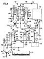
- FIG. 1 shown as a whole and designated 100 liquid medium processing plant comprises a container 102 in which the liquid medium to be treated, for example, a washing liquid containing ferritic particles is contained.
- a liquid supply line 104 in which a liquid pump 106 and a heat exchanger 108 are arranged, leads to a branch 110.
- a first supply line 112a which can be shut off by means of a check valve 114a, leads to an inlet of a first magnetic separator 116a, while a second supply line 112b, which can be shut off by means of a check valve 114b, leads to an inlet of a second magnetic separator 116b.
- the first magnetic separator 116a includes a base 118 having an upper cylindrical portion 120 and a lower conically downwardly tapered portion 122.
- the upper end of the main body 118 is closed by a cover 124, from the underside of which an inner tube 126 coaxial with the upper section 120 of the main body 118 projects into the interior of the main body 118 forming a collecting chamber 128.
- a flap valve 130 is arranged, through which the collecting chamber 128 can be separated from a lock chamber 132 arranged below the flap valve 130.
- a slide valve 134 is arranged, through which the lock chamber 132 can be separated from a arranged below the slide valve 134 outlet pipe 136.
- the first magnetic separator 116a includes a plurality of magnetic elements 138, which consists of a in Fig. 1 shown rest position, in which the magnetic elements 138 are spaced from the base body 118, in an in Fig. 1 in the second magnetic separator 116b illustrated operating position can be brought, in which the magnetic elements 138 abut against the base body 118 of the magnetic separator.
- the base body 118 is formed of a non-magnetic metallic material, such as a VA steel, so that the magnetic field generated by the magnetic elements 138 extends in the working position magnetic elements 138 into the collection chamber 128 into it.
- a first discharge line 140a which can be shut off by means of a check valve 142a, leads to a merger 144.
- the second magnetic separator 116b is formed in the same manner as the first magnetic separator 116a described above, and has an outlet which is connected to the merging 144 via a second discharge line 140b, which can be shut off by means of a check valve 142b.
- the two magnetic separators 116a, 116b are thus connected in parallel to each other and are flowed through in the operation of the liquid medium processing plant 100 in alternation of the liquid medium to be processed from the container 102.
- the flow direction of the liquid medium is in Fig. 1 indicated by the arrows 148.
- the second magnetic separator 116b is located in the in Fig. 1 illustrated situation in a collection phase in which the magnetic elements 138 are arranged in their working position on the base body 118, so that the ferritic particles which are contained in the collecting medium 128 flowing through the liquid medium, in a collecting region 148 which is surrounded by the magnetic elements 138 to be withheld.
- the check valves 114b and 142b are closed, and the check valves 114a and 142a are opened, so that now the first magnetic separator 116a is flowed through by the liquid medium from the container 102.
- the first magnetic separator 116a enters its collection phase, in which the magnetic elements 138 are in their working position on the main body 118.
- the second magnetic separator 116b enters a sedimentation phase in which the magnetic elements 138 are brought from the working position to the rest position, in which they no longer hold the ferritic particles in the collecting region 148, and then the flap valve 130 is opened, whereby At the upper end of the collection chamber 128, air cushions are released and a pulse-like movement is triggered in the fluid column arranged beneath the air cushions, by means of which the ferritic particles are substantially completely detached from the inside of the main body 118 in the collecting region 148.
- the detached particles sink under the action of gravity through the collection chamber 128 down and pass through the open flap valve 130 in the lock chamber 132, the lower end is closed by the slide valve 134.
- the sedimentation phase of the second magnetic separator 116b is ended by closing the flap valve 130.
- the slide valve 134 is opened, so that the particles contained in the lock chamber 132 together with residual liquid from the collection chamber 128 fall through the outlet pipe 136 down.
- the second magnetic separator 116b is again switched to its collection phase, and a new operating cycle of the second magnetic separator 116b begins.
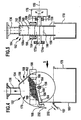
- a solids separator 152 Disposed below each of the magnetic separators 116a, 116b is a solids separator 152, which serves to separate the particles passing through the outlet tube 136 from the entrained liquid, and will now be described with reference to FIGS Fig. 2, to 7 will be described in more detail.
- Each solids separator 152 comprises a collection container 154, which has two substantially planar, substantially congruent to one another, parallel aligned and along a rotation axis 156 of the sump 154 spaced side walls 158.
- the two side walls 158 are by means of a substantially radially to the rotation axis 156 aligned bottom wall 160, extending from a radially outer end of the bottom wall 160 substantially perpendicular to the bottom wall 160 extending front wall 162, one of the radially inner End of the bottom wall 160 of extending and with the top of the bottom wall 160 an obtuse angle ⁇ enclosing rear drain wall 164 and a remote from the bottom wall 160 outer end of the drain wall 164 and extending from the drain wall 164 substantially vertically downwardly extending spout wall 166th connected with each other.
- FIG. 3 How best Fig. 3 can be seen extends from the outside of the Fig. 3
- a first rotary shaft part 172 a along the axis of rotation 156 to the outside which is rotatably mounted in a (only schematically illustrated) first bearing 174 a about the axis of rotation 156.
- a second rotary shaft part 172b extends outward along the axis of rotation 156, which is rotatably mounted about the axis of rotation 156 in a second bearing 174b.
- a rotary drive device 176 At the outer end of the second rotary shaft part 172b engages a rotary drive device 176, by means of which the rotary shaft part 172b and thus the other, rigidly connected to the rotary shaft part 172b elements of the collecting container 154 are rotatable about the rotation axis 156.
- a stationary upwardly open solid container 178 is arranged below the collecting container 154.
- a rear wall 180 of the solids container 178 At the upper edge of a rear wall 180 of the solids container 178 is a (in the Figures 2 . 4 and 6 only partially shown) collecting hopper 182 arranged for draining from the sump 178 liquid.
- a stop 184 disposed between the side walls 158 of the collecting container 154 is held, which serves to limit the rotational travel of the collecting container 154.
- the stop 184 may include an elastic material to dampen the impact of the collection container 154 on the stop 184.
- the solids separator 152 comprises a stationary heating device 186 arranged between the side walls 158 of the collecting container 154, which has two lateral heating surfaces 188, which are in contact with the inside of the respectively adjacent side wall 158 of the collecting container 154, and an upper heating surface 189, which in the hereinafter described liquid drainage position of the collecting container 154 is in contact with the outside of the drainage wall 164.
- Heat can be transferred from the heater 186 to the side walls 158 (rotatable relative to the heater 186) via these heating surfaces 188.
- the heating device 186 is designed as a heat exchanger through which steam flows.
- the solids separator 152 includes a plurality of magnetic members 190 disposed in two substantially horizontal rows extending above the axis of rotation 156 of the sump 154, on both sides of the sump 154 and adjacent to the outsides of the side walls 158.
- the sump 154 is made of a non-magnetic metallic material, such as a VA steel, so that the magnetic field generated by the magnetic elements 190 extends into the space between the side walls 158 of the sump 154.
- the magnetic elements 190 may be formed in particular as permanent magnets.
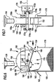
- the collecting container 154 can by means of the rotary drive device 176 in three different working positions, namely one in the FIGS. 2 and 3 shown filling position, one in the 4 and 5 shown liquid drainage position and a in the 6 and 7 shown Feststoffausbring ein be brought.
- the collecting container 154 is brought into the filling position before the slide valve 134 of the magnetic separator 116a or 116b arranged above the solids separator 152 is opened.
- the collecting container 154 remains in the filling position over several discharge phases of the associated magnetic separator until the filling level 192 of the collecting trough 168 has almost reached the upper edge of the front wall 162 or the drain wall 164.
- the ferritic particles filled in the collecting trough 168 adhere to the side walls of the collecting trough 168 due to the effect of the magnetic field generated by the magnetic elements 190.
- the sump 154 is slowly (in the direction of the Fig. 2 seen) in the counterclockwise direction from the filling position in the in the 4 and 5 shown liquid drainage position rotated in which the drain wall 164 of the sump 168 abuts the upper heating surface 189 of the heater 186 and is inclined to the horizontal that its radially outer edge below the bottom wall 160 facing edge of the drain wall 164 is located so that the drain wall 164 in this position has a directed to the spout wall 166 slope.
- the ferritic particles contained in the sump 168 are retained by the action of the magnetic field generated by the magnetic elements 190, even in the liquid draining position on the side walls 158 of the sump 168, so that they do not enter the collection hopper 182.
- the sump 154 is heated by the heater 186 so that the solids left in the sump 168 are dried.
- the sump is rotated by means of the rotary drive device 176 (in the direction of view of FIG Fig. 4 seen) clockwise from the liquid drainage position in the in the 6 and 7 shown Feststoffausbring ein brought in which the bottom wall 160 of the sump 168 from below abuts the stop 184 and the passage opening 170 of the sump 168 is directed downward, so that the solid particles from the sump 168 under the action of gravity through the passage opening 170 in the Solid container 178 arrive.
- the entire sump 168 is below the axis of rotation 156 of the sump 154 where no magnetic elements 190 are disposed so that the ferritic particles are not retained by the magnetic field on the sidewalls of the sump 168 in the solids disengagement position.
- the sump 154 is rotated by means of the rotary drive device 176 (in the direction of view of FIG Fig. 2 seen) in the counterclockwise direction in the above-described filling position turned back to receive new solid particles and liquid.
- the collecting funnels 182 associated with the solids separators 152 are connected via a respective liquid discharge line 194a, 194b to a junction 196, from which a supply line 198 leads to an inlet of an evaporator 200.
- the supply line opens into a cooking zone 202 of the evaporator 200, which is separated from an oil collection chamber 204 of the evaporator via a partition wall 206 with an overflow 208.
- the cooking zone 202 is filled up to a bath level 210 with a liquid bath 212 into which a heating device 214 immerses, with which the liquid in the liquid bath 212 can be heated above its boiling point.
- oil constituents contained in the liquid coming from the solids separators 152 form an oil layer on the upper side of the liquid bath 212, from where this oil-containing phase passes via the overflow 208 into the oil collecting space 204 of the evaporator 200.
- Vapor from the liquid to be treated formed by the evaporation of the liquid in the liquid bath 212 passes via a discharge arranged at the top of the evaporator 200 into a steam discharge line 218 and thence into the steam side of the heat exchanger 108 in which the steam heats heat to the liquid pumped out of the container 102 Liquids releases and condenses.
- the condensate from the heat exchanger 108 passes through a condensate line 220 in a condensate collection 222.
- Steam branch lines 224a, 224b branch off from the steam discharge line 218, through which steam from the steam discharge line 218 can be supplied to the collecting containers 154 to the heating devices 186 designed as heat exchangers.
- the steam in the heaters 186 transfers heat to the headers 154 of the solids separators 152 to dry the solids in the headers 168 and condenses.
- the condensate passes via Kondensatab2009 Gustaven 226 a, 226 b to a merge 228, from which a condensate line 230 leads to the condensate collecting tank 222.
- the condensate from the condensate collection container 222 is conveyed into the container 102 via a condensate return line 230, in which a condensate pump 232 is arranged.
- the container 102 is thus removed continuously to be purified liquid medium and purified liquid medium via the liquid return line 146 and recycled by distillation recycled condensate from the condensate collection tank 222 via the condensate return line 230.
Landscapes
- Centrifugal Separators (AREA)
- Vaporization, Distillation, Condensation, Sublimation, And Cold Traps (AREA)
- Manufacture And Refinement Of Metals (AREA)
- Excavating Of Shafts Or Tunnels (AREA)
- Filtration Of Liquid (AREA)
- Treatment Of Liquids With Adsorbents In General (AREA)
- Sink And Installation For Waste Water (AREA)
- Filling Of Jars Or Cans And Processes For Cleaning And Sealing Jars (AREA)
Applications Claiming Priority (3)
| Application Number | Priority Date | Filing Date | Title |
|---|---|---|---|
| DE10251570A DE10251570A1 (de) | 2002-11-06 | 2002-11-06 | Feststoffseparator |
| DE10251570 | 2002-11-06 | ||
| PCT/EP2003/012193 WO2004041438A1 (de) | 2002-11-06 | 2003-11-03 | Feststoffseparator |
Publications (2)
| Publication Number | Publication Date |
|---|---|
| EP1558396A1 EP1558396A1 (de) | 2005-08-03 |
| EP1558396B1 true EP1558396B1 (de) | 2010-06-02 |
Family
ID=32115273
Family Applications (1)
| Application Number | Title | Priority Date | Filing Date |
|---|---|---|---|
| EP03775279A Expired - Lifetime EP1558396B1 (de) | 2002-11-06 | 2003-11-03 | Feststoffseparator |
Country Status (11)
| Country | Link |
|---|---|
| US (1) | US7357260B2 (pl) |
| EP (1) | EP1558396B1 (pl) |
| JP (1) | JP4741238B2 (pl) |
| CN (1) | CN100588465C (pl) |
| AT (1) | ATE469700T1 (pl) |
| AU (1) | AU2003283338A1 (pl) |
| CA (1) | CA2480262C (pl) |
| DE (2) | DE10251570A1 (pl) |
| MX (1) | MXPA05001190A (pl) |
| PL (1) | PL371316A1 (pl) |
| WO (1) | WO2004041438A1 (pl) |
Families Citing this family (14)
| Publication number | Priority date | Publication date | Assignee | Title |
|---|---|---|---|---|
| DE102006010842A1 (de) | 2006-03-09 | 2007-09-13 | Dürr Ecoclean GmbH | Vorrichtung und Verfahren zum Aufbereiten von rückgespültem Fluid |
| DE102006010843A1 (de) | 2006-03-09 | 2007-09-13 | Dürr Ecoclean GmbH | Filtervorrichtung und Filterverfahren |
| CA2675108A1 (en) * | 2007-01-09 | 2008-07-17 | Cambridge Water Technology, Inc. | Improved collection system for a wet drum magnetic separator |
| NL1033644C2 (nl) * | 2007-04-04 | 2008-10-07 | Recco B V | Hooggradient magneetscheidingseenheid met instelmiddelen en opvangplaat. |
| DE202007005082U1 (de) * | 2007-04-05 | 2007-10-11 | Dürr Ecoclean GmbH | Vorrichtung zum Aufbereiten von rückgespültem Fluid |
| GB0724404D0 (en) * | 2007-05-29 | 2008-01-30 | Invitrogen Dynal As | A sample vessel retaining portion |
| DE502007004200D1 (de) * | 2007-08-14 | 2010-08-05 | Qiagen Gmbh | Verfahren zum Suspendieren oder Resuspendieren von Partikeln in einer Lösung sowie daran angepasste Vorrichtung |
| US8309711B2 (en) * | 2009-08-07 | 2012-11-13 | Corn Products Development Inc. | Filtration of corn starch followed by washing and collection of the resultant corn starch cake |
| FI20115350A0 (fi) * | 2011-04-12 | 2011-04-12 | Steris Europe Inc | Laite kiintoaineen erottamiseksi biojätesuspensiosta |
| WO2013189549A1 (de) * | 2012-06-22 | 2013-12-27 | Norbert Ruez Gmbh & Co.Kg | Vorrichtung zum abscheiden magnetisierbarer verunreinigungen aus strömenden fluiden |
| US9242251B2 (en) | 2013-01-30 | 2016-01-26 | Wheelabrator Group, Inc. | Magnetic separator with dynamic baffle system |
| CN104043523A (zh) * | 2013-03-11 | 2014-09-17 | 昆山宝腾橡塑胶材料科技有限公司 | 一种金属自动分离器 |
| EP3806975B1 (en) * | 2018-06-13 | 2024-12-04 | Cargill, Incorporated | A filtration process |
| CN112756615B (zh) * | 2020-12-28 | 2023-05-09 | 赣州睿达磁性材料有限公司 | 一种利用烧结钕铁硼废料制备再生粘结磁体的工艺方法及设备 |
Family Cites Families (17)
| Publication number | Priority date | Publication date | Assignee | Title |
|---|---|---|---|---|
| BE481512A (pl) * | ||||
| GB1190203A (en) * | 1966-11-15 | 1970-04-29 | M E L Equipment Co Ltd | Improvements in or relating to Apparatus for Separating Ferromagnetic Material from a Liquid |
| SE395621B (sv) * | 1974-01-28 | 1977-08-22 | Asea Ab | Forfaringssett och anordning for malmseparering vid forhojd temperatur |
| US3985649A (en) * | 1974-11-25 | 1976-10-12 | Eddelman Roy T | Ferromagnetic separation process and material |
| GB1576427A (en) * | 1976-04-29 | 1980-10-08 | English Clays Lovering Pochin | Magnetic separators |
| DE3512207A1 (de) * | 1985-04-03 | 1986-10-16 | Dürr GmbH, 7000 Stuttgart | Verfahren und vorrichtung zum wiederaufbereiten von waessrigen, oel- und fetthaltigen reiniungsloesungen |
| AT392020B (de) * | 1989-09-18 | 1991-01-10 | Elin Union Ag | Verfahren zur selektiven, trockenen scheidung von unterschiedlich magnetisierbarem feinkorn |
| DE9209279U1 (de) * | 1992-07-10 | 1992-09-17 | Hagemann, Andreas, 7516 Karlsbad | Vorrichtung zur Reinigung von ferromagnetischem Schrott |
| DE4418345A1 (de) * | 1994-05-26 | 1995-11-30 | Windhorst Beteiligungsgesellsc | Magnetisches Filtersystem zum Abtrennen von fein verteilten ferromagnetischen Verunreinigungen aus Flüssigkeiten oder Schüttgütern |
| JP3115501B2 (ja) * | 1994-06-15 | 2000-12-11 | プレシジョン・システム・サイエンス株式会社 | 分注機を利用した磁性体の脱着制御方法及びこの方法によって処理される各種装置 |
| JP4060468B2 (ja) * | 1994-06-15 | 2008-03-12 | プレシジョン・システム・サイエンス株式会社 | 分注機を利用した磁性体の脱着制御方法及びこの方法によって処理される各種装置 |
| DE4421058A1 (de) * | 1994-06-16 | 1995-12-21 | Boehringer Mannheim Gmbh | Verfahren zur magnetischen Abtrennung von Flüssigkeitskomponenten |
| US5837144A (en) * | 1994-06-16 | 1998-11-17 | Boehringer Mannheim Gmbh | Method of magnetically separating liquid components |
| LU90273B1 (de) * | 1998-08-11 | 2000-02-14 | Wurth Paul Sa | Verfahren zur thermischen Behandlung schwermetall-und eisenoxidhaltiger Reststoffe |
| US6764859B1 (en) * | 1999-07-19 | 2004-07-20 | Biomerieux, B.V. | Device and method for mixing magnetic particles with a fluid |
| DE10006262B4 (de) * | 2000-02-12 | 2005-12-01 | Dürr Ecoclean GmbH | Magnetabscheider |
| DE10030412B4 (de) * | 2000-06-21 | 2006-02-09 | Bematec S.A. | Magnetabscheider mit drehbarer Klappe |
-
2002
- 2002-11-06 DE DE10251570A patent/DE10251570A1/de not_active Withdrawn
-
2003
- 2003-11-03 AT AT03775279T patent/ATE469700T1/de active
- 2003-11-03 AU AU2003283338A patent/AU2003283338A1/en not_active Abandoned
- 2003-11-03 CN CN200380100455A patent/CN100588465C/zh not_active Expired - Fee Related
- 2003-11-03 PL PL03371316A patent/PL371316A1/pl not_active IP Right Cessation
- 2003-11-03 DE DE50312781T patent/DE50312781D1/de not_active Expired - Lifetime
- 2003-11-03 CA CA002480262A patent/CA2480262C/en not_active Expired - Fee Related
- 2003-11-03 JP JP2004548846A patent/JP4741238B2/ja not_active Expired - Fee Related
- 2003-11-03 MX MXPA05001190A patent/MXPA05001190A/es active IP Right Grant
- 2003-11-03 WO PCT/EP2003/012193 patent/WO2004041438A1/de not_active Ceased
- 2003-11-03 EP EP03775279A patent/EP1558396B1/de not_active Expired - Lifetime
-
2004
- 2004-10-19 US US10/968,627 patent/US7357260B2/en not_active Expired - Fee Related
Also Published As
| Publication number | Publication date |
|---|---|
| CN1691982A (zh) | 2005-11-02 |
| US7357260B2 (en) | 2008-04-15 |
| ATE469700T1 (de) | 2010-06-15 |
| AU2003283338A1 (en) | 2004-06-07 |
| US20050189303A1 (en) | 2005-09-01 |
| DE50312781D1 (de) | 2010-07-15 |
| DE10251570A1 (de) | 2004-05-19 |
| CA2480262A1 (en) | 2004-05-21 |
| EP1558396A1 (de) | 2005-08-03 |
| JP2006504522A (ja) | 2006-02-09 |
| CA2480262C (en) | 2008-03-25 |
| CN100588465C (zh) | 2010-02-10 |
| MXPA05001190A (es) | 2005-05-16 |
| WO2004041438A1 (de) | 2004-05-21 |
| JP4741238B2 (ja) | 2011-08-03 |
| PL371316A1 (pl) | 2005-06-13 |
Similar Documents
| Publication | Publication Date | Title |
|---|---|---|
| EP1558396B1 (de) | Feststoffseparator | |
| DE69736128T2 (de) | Vorrichtung und Verfahren zum Trennen einer leichten Flüssigkeit von einer schweren Flüssigkeit | |
| DE69735774T2 (de) | Trennvorrichtung | |
| EP0196644B1 (de) | Verfahren und Vorrichtung zum Wiederaufbereiten von wässrigen , öl- und fetthaltigen Reinigungslösungen | |
| EP0835681A2 (de) | Verfahren und Vorrichtung zur Reinigung und Aufbereitung von in der Hüttenindustrie benutzten Kühl- und/oder Schmiermitteln | |
| EP3778088A1 (de) | Reflow-kondensationslötanlage | |
| DE4239083A1 (pl) | ||
| EP1194383B1 (de) | Vorrichtung zum entwässern von schlamm | |
| DE19524276A1 (de) | Vorrichtung zum Entfernen von Abscheidegut aus in einem Gerinne strömender Flüssigkeit | |
| DE3641924A1 (de) | Vorrichtung zum entwaessern von bei der reinigung von brennstoffseparatoren angefallenen brennstoffen, insbesondere zur installierung auf schiffen | |
| WO1980002138A1 (fr) | Procede et dispositif pour la separation d'huile a partir d'un melange eau-huile | |
| EP0282906A2 (de) | Fettabscheider | |
| DE3503486A1 (de) | Abscheidevorrichtung | |
| DE4320814C2 (de) | Diskontinuierliches Sedimentationsverfahren und Einrichtung zum Entölen eines ölhaltigen Flüssigkeitsgemisches | |
| DE2512291C2 (de) | Vorrichtung zum Abscheiden von Öl aus einem Öl-Wasser-Gemisch | |
| DE10201916A1 (de) | Vorrichtung zum kontinuierlichen Trennen von aufschwimmbaren und sedimentierbaren Stoffen aus damit verunreinigtem Wasser | |
| DE19721629C1 (de) | Aufstromsortierer | |
| DE29700914U1 (de) | Vorrichtung zum Spülen und Reinigen von mit wäßrigen Trennmedien benetztem Trenngut | |
| DE60118177T2 (de) | Verfahren und vorrichtung für ein saugelement | |
| DE29810474U1 (de) | Vorrichtung zum Eindicken von Schlämmen | |
| DE2713266A1 (de) | Fluessigkeitsbehandlungssystem mit dampfkompression | |
| DE102013100694B4 (de) | Verfahren und Vorrichtung zur Aufbereitung einer von Zusatzstoffen verunreinigten Basisflüssikeit | |
| EP1386650B1 (de) | Abscheidersystem zum Abtrennen einer leichteren Phase aus einem Abwasser | |
| DE19729514C1 (de) | Dampfbeheizte Vorrichtung zur Verdampfung oder Eindickung von Flüssigkeiten | |
| DE69211519T2 (de) | Trockenreinigungsanlage für verschiedene Artikel |
Legal Events
| Date | Code | Title | Description |
|---|---|---|---|
| PUAI | Public reference made under article 153(3) epc to a published international application that has entered the european phase |
Free format text: ORIGINAL CODE: 0009012 |
|
| 17P | Request for examination filed |
Effective date: 20040608 |
|
| AK | Designated contracting states |
Kind code of ref document: A1 Designated state(s): AT BE BG CH CY CZ DE DK EE ES FI FR GB GR HU IE IT LI LU MC NL PT RO SE SI SK TR |
|
| AX | Request for extension of the european patent |
Extension state: AL LT LV MK |
|
| GRAP | Despatch of communication of intention to grant a patent |
Free format text: ORIGINAL CODE: EPIDOSNIGR1 |
|
| GRAS | Grant fee paid |
Free format text: ORIGINAL CODE: EPIDOSNIGR3 |
|
| GRAA | (expected) grant |
Free format text: ORIGINAL CODE: 0009210 |
|
| AK | Designated contracting states |
Kind code of ref document: B1 Designated state(s): AT BE BG CH CY CZ DE DK EE ES FI FR GB GR HU IE IT LI LU MC NL PT RO SE SI SK TR |
|
| AX | Request for extension of the european patent |
Extension state: AL LT LV MK |
|
| REG | Reference to a national code |
Ref country code: GB Ref legal event code: FG4D Free format text: NOT ENGLISH |
|
| REG | Reference to a national code |
Ref country code: CH Ref legal event code: EP |
|
| REG | Reference to a national code |
Ref country code: IE Ref legal event code: FG4D Free format text: LANGUAGE OF EP DOCUMENT: GERMAN |
|
| REF | Corresponds to: |
Ref document number: 50312781 Country of ref document: DE Date of ref document: 20100715 Kind code of ref document: P |
|
| REG | Reference to a national code |
Ref country code: NL Ref legal event code: VDEP Effective date: 20100602 |
|
| PG25 | Lapsed in a contracting state [announced via postgrant information from national office to epo] |
Ref country code: SE Free format text: LAPSE BECAUSE OF FAILURE TO SUBMIT A TRANSLATION OF THE DESCRIPTION OR TO PAY THE FEE WITHIN THE PRESCRIBED TIME-LIMIT Effective date: 20100602 |
|
| LTIE | Lt: invalidation of european patent or patent extension |
Effective date: 20100602 |
|
| PG25 | Lapsed in a contracting state [announced via postgrant information from national office to epo] |
Ref country code: FI Free format text: LAPSE BECAUSE OF FAILURE TO SUBMIT A TRANSLATION OF THE DESCRIPTION OR TO PAY THE FEE WITHIN THE PRESCRIBED TIME-LIMIT Effective date: 20100602 Ref country code: SI Free format text: LAPSE BECAUSE OF FAILURE TO SUBMIT A TRANSLATION OF THE DESCRIPTION OR TO PAY THE FEE WITHIN THE PRESCRIBED TIME-LIMIT Effective date: 20100602 |
|
| PG25 | Lapsed in a contracting state [announced via postgrant information from national office to epo] |
Ref country code: GR Free format text: LAPSE BECAUSE OF FAILURE TO SUBMIT A TRANSLATION OF THE DESCRIPTION OR TO PAY THE FEE WITHIN THE PRESCRIBED TIME-LIMIT Effective date: 20100903 Ref country code: CY Free format text: LAPSE BECAUSE OF FAILURE TO SUBMIT A TRANSLATION OF THE DESCRIPTION OR TO PAY THE FEE WITHIN THE PRESCRIBED TIME-LIMIT Effective date: 20100602 |
|
| REG | Reference to a national code |
Ref country code: IE Ref legal event code: FD4D |
|
| PG25 | Lapsed in a contracting state [announced via postgrant information from national office to epo] |
Ref country code: IE Free format text: LAPSE BECAUSE OF FAILURE TO SUBMIT A TRANSLATION OF THE DESCRIPTION OR TO PAY THE FEE WITHIN THE PRESCRIBED TIME-LIMIT Effective date: 20100602 Ref country code: EE Free format text: LAPSE BECAUSE OF FAILURE TO SUBMIT A TRANSLATION OF THE DESCRIPTION OR TO PAY THE FEE WITHIN THE PRESCRIBED TIME-LIMIT Effective date: 20100602 Ref country code: NL Free format text: LAPSE BECAUSE OF FAILURE TO SUBMIT A TRANSLATION OF THE DESCRIPTION OR TO PAY THE FEE WITHIN THE PRESCRIBED TIME-LIMIT Effective date: 20100602 |
|
| PGFP | Annual fee paid to national office [announced via postgrant information from national office to epo] |
Ref country code: AT Payment date: 20101112 Year of fee payment: 8 Ref country code: FR Payment date: 20101130 Year of fee payment: 8 |
|
| PG25 | Lapsed in a contracting state [announced via postgrant information from national office to epo] |
Ref country code: RO Free format text: LAPSE BECAUSE OF FAILURE TO SUBMIT A TRANSLATION OF THE DESCRIPTION OR TO PAY THE FEE WITHIN THE PRESCRIBED TIME-LIMIT Effective date: 20100602 Ref country code: PT Free format text: LAPSE BECAUSE OF FAILURE TO SUBMIT A TRANSLATION OF THE DESCRIPTION OR TO PAY THE FEE WITHIN THE PRESCRIBED TIME-LIMIT Effective date: 20101004 Ref country code: CZ Free format text: LAPSE BECAUSE OF FAILURE TO SUBMIT A TRANSLATION OF THE DESCRIPTION OR TO PAY THE FEE WITHIN THE PRESCRIBED TIME-LIMIT Effective date: 20100602 Ref country code: SK Free format text: LAPSE BECAUSE OF FAILURE TO SUBMIT A TRANSLATION OF THE DESCRIPTION OR TO PAY THE FEE WITHIN THE PRESCRIBED TIME-LIMIT Effective date: 20100602 |
|
| PG25 | Lapsed in a contracting state [announced via postgrant information from national office to epo] |
Ref country code: IT Free format text: LAPSE BECAUSE OF FAILURE TO SUBMIT A TRANSLATION OF THE DESCRIPTION OR TO PAY THE FEE WITHIN THE PRESCRIBED TIME-LIMIT Effective date: 20100602 |
|
| PLBE | No opposition filed within time limit |
Free format text: ORIGINAL CODE: 0009261 |
|
| STAA | Information on the status of an ep patent application or granted ep patent |
Free format text: STATUS: NO OPPOSITION FILED WITHIN TIME LIMIT |
|
| PG25 | Lapsed in a contracting state [announced via postgrant information from national office to epo] |
Ref country code: DK Free format text: LAPSE BECAUSE OF FAILURE TO SUBMIT A TRANSLATION OF THE DESCRIPTION OR TO PAY THE FEE WITHIN THE PRESCRIBED TIME-LIMIT Effective date: 20100602 |
|
| 26N | No opposition filed |
Effective date: 20110303 |
|
| BERE | Be: lapsed |
Owner name: DURR ECOCLEAN G.M.B.H. Effective date: 20101130 |
|
| REG | Reference to a national code |
Ref country code: DE Ref legal event code: R097 Ref document number: 50312781 Country of ref document: DE Effective date: 20110302 |
|
| PG25 | Lapsed in a contracting state [announced via postgrant information from national office to epo] |
Ref country code: MC Free format text: LAPSE BECAUSE OF NON-PAYMENT OF DUE FEES Effective date: 20101130 |
|
| REG | Reference to a national code |
Ref country code: CH Ref legal event code: PL |
|
| GBPC | Gb: european patent ceased through non-payment of renewal fee |
Effective date: 20101103 |
|
| PG25 | Lapsed in a contracting state [announced via postgrant information from national office to epo] |
Ref country code: LI Free format text: LAPSE BECAUSE OF NON-PAYMENT OF DUE FEES Effective date: 20101130 Ref country code: CH Free format text: LAPSE BECAUSE OF NON-PAYMENT OF DUE FEES Effective date: 20101130 |
|
| PG25 | Lapsed in a contracting state [announced via postgrant information from national office to epo] |
Ref country code: BE Free format text: LAPSE BECAUSE OF NON-PAYMENT OF DUE FEES Effective date: 20101130 |
|
| PG25 | Lapsed in a contracting state [announced via postgrant information from national office to epo] |
Ref country code: GB Free format text: LAPSE BECAUSE OF NON-PAYMENT OF DUE FEES Effective date: 20101103 |
|
| REG | Reference to a national code |
Ref country code: FR Ref legal event code: ST Effective date: 20120731 |
|
| PG25 | Lapsed in a contracting state [announced via postgrant information from national office to epo] |
Ref country code: HU Free format text: LAPSE BECAUSE OF FAILURE TO SUBMIT A TRANSLATION OF THE DESCRIPTION OR TO PAY THE FEE WITHIN THE PRESCRIBED TIME-LIMIT Effective date: 20101203 Ref country code: LU Free format text: LAPSE BECAUSE OF NON-PAYMENT OF DUE FEES Effective date: 20101103 Ref country code: BG Free format text: LAPSE BECAUSE OF FAILURE TO SUBMIT A TRANSLATION OF THE DESCRIPTION OR TO PAY THE FEE WITHIN THE PRESCRIBED TIME-LIMIT Effective date: 20100602 |
|
| PG25 | Lapsed in a contracting state [announced via postgrant information from national office to epo] |
Ref country code: TR Free format text: LAPSE BECAUSE OF FAILURE TO SUBMIT A TRANSLATION OF THE DESCRIPTION OR TO PAY THE FEE WITHIN THE PRESCRIBED TIME-LIMIT Effective date: 20100602 |
|
| REG | Reference to a national code |
Ref country code: AT Ref legal event code: MM01 Ref document number: 469700 Country of ref document: AT Kind code of ref document: T Effective date: 20111103 |
|
| PG25 | Lapsed in a contracting state [announced via postgrant information from national office to epo] |
Ref country code: FR Free format text: LAPSE BECAUSE OF NON-PAYMENT OF DUE FEES Effective date: 20111130 |
|
| PG25 | Lapsed in a contracting state [announced via postgrant information from national office to epo] |
Ref country code: AT Free format text: LAPSE BECAUSE OF NON-PAYMENT OF DUE FEES Effective date: 20111103 |
|
| PG25 | Lapsed in a contracting state [announced via postgrant information from national office to epo] |
Ref country code: BG Free format text: LAPSE BECAUSE OF FAILURE TO SUBMIT A TRANSLATION OF THE DESCRIPTION OR TO PAY THE FEE WITHIN THE PRESCRIBED TIME-LIMIT Effective date: 20100902 |
|
| PG25 | Lapsed in a contracting state [announced via postgrant information from national office to epo] |
Ref country code: ES Free format text: LAPSE BECAUSE OF FAILURE TO SUBMIT A TRANSLATION OF THE DESCRIPTION OR TO PAY THE FEE WITHIN THE PRESCRIBED TIME-LIMIT Effective date: 20100913 |
|
| REG | Reference to a national code |
Ref country code: DE Ref legal event code: R082 Ref document number: 50312781 Country of ref document: DE Representative=s name: HOEGER, STELLRECHT & PARTNER PATENTANWAELTE MB, DE |
|
| PGFP | Annual fee paid to national office [announced via postgrant information from national office to epo] |
Ref country code: DE Payment date: 20171121 Year of fee payment: 15 |
|
| REG | Reference to a national code |
Ref country code: DE Ref legal event code: R082 Ref document number: 50312781 Country of ref document: DE Representative=s name: HOEGER, STELLRECHT & PARTNER PATENTANWAELTE MB, DE Ref country code: DE Ref legal event code: R081 Ref document number: 50312781 Country of ref document: DE Owner name: ECOCLEAN GMBH, DE Free format text: FORMER OWNER: DUERR ECOCLEAN GMBH, 70794 FILDERSTADT, DE |
|
| REG | Reference to a national code |
Ref country code: DE Ref legal event code: R119 Ref document number: 50312781 Country of ref document: DE |
|
| PG25 | Lapsed in a contracting state [announced via postgrant information from national office to epo] |
Ref country code: DE Free format text: LAPSE BECAUSE OF NON-PAYMENT OF DUE FEES Effective date: 20190601 |