EP1555933B1 - Sensorsystem für die bestimmung der glukose-konzentration im blut - Google Patents
Sensorsystem für die bestimmung der glukose-konzentration im blut Download PDFInfo
- Publication number
- EP1555933B1 EP1555933B1 EP03750231A EP03750231A EP1555933B1 EP 1555933 B1 EP1555933 B1 EP 1555933B1 EP 03750231 A EP03750231 A EP 03750231A EP 03750231 A EP03750231 A EP 03750231A EP 1555933 B1 EP1555933 B1 EP 1555933B1
- Authority
- EP
- European Patent Office
- Prior art keywords
- sensor
- sensor system
- magnet
- glucose
- measuring
- Prior art date
- Legal status (The legal status is an assumption and is not a legal conclusion. Google has not performed a legal analysis and makes no representation as to the accuracy of the status listed.)
- Expired - Lifetime
Links
- 239000008103 glucose Substances 0.000 title claims abstract description 44
- WQZGKKKJIJFFOK-GASJEMHNSA-N Glucose Natural products OC[C@H]1OC(O)[C@H](O)[C@@H](O)[C@@H]1O WQZGKKKJIJFFOK-GASJEMHNSA-N 0.000 title claims abstract description 43
- 239000008280 blood Substances 0.000 title claims description 18
- 210000004369 blood Anatomy 0.000 title claims description 18
- 238000005259 measurement Methods 0.000 claims abstract description 23
- 239000004033 plastic Substances 0.000 claims abstract description 16
- 239000003708 ampul Substances 0.000 claims abstract description 9
- 239000000203 mixture Substances 0.000 claims abstract description 8
- 238000011156 evaluation Methods 0.000 claims abstract description 4
- 238000002156 mixing Methods 0.000 claims abstract description 3
- 239000007788 liquid Substances 0.000 claims description 37
- 230000008878 coupling Effects 0.000 claims description 7
- 238000010168 coupling process Methods 0.000 claims description 7
- 238000005859 coupling reaction Methods 0.000 claims description 7
- 238000013016 damping Methods 0.000 claims description 4
- 230000000694 effects Effects 0.000 claims description 3
- 230000010355 oscillation Effects 0.000 claims 4
- 230000035515 penetration Effects 0.000 claims 2
- 238000000265 homogenisation Methods 0.000 claims 1
- 230000008859 change Effects 0.000 abstract description 2
- 239000012530 fluid Substances 0.000 abstract 4
- 239000012466 permeate Substances 0.000 abstract 2
- 230000003534 oscillatory effect Effects 0.000 abstract 1
- 238000005452 bending Methods 0.000 description 11
- 230000006399 behavior Effects 0.000 description 7
- 206010012601 diabetes mellitus Diseases 0.000 description 6
- 230000005284 excitation Effects 0.000 description 4
- 239000000758 substrate Substances 0.000 description 4
- 208000015181 infectious disease Diseases 0.000 description 3
- 239000000463 material Substances 0.000 description 3
- 238000012544 monitoring process Methods 0.000 description 3
- 125000006850 spacer group Chemical group 0.000 description 3
- 238000011282 treatment Methods 0.000 description 3
- 229920002307 Dextran Polymers 0.000 description 2
- 206010067584 Type 1 diabetes mellitus Diseases 0.000 description 2
- 230000008901 benefit Effects 0.000 description 2
- 238000011161 development Methods 0.000 description 2
- 230000018109 developmental process Effects 0.000 description 2
- 238000010586 diagram Methods 0.000 description 2
- 230000006870 function Effects 0.000 description 2
- 238000002513 implantation Methods 0.000 description 2
- 239000007924 injection Substances 0.000 description 2
- 238000002347 injection Methods 0.000 description 2
- NOESYZHRGYRDHS-UHFFFAOYSA-N insulin Chemical compound N1C(=O)C(NC(=O)C(CCC(N)=O)NC(=O)C(CCC(O)=O)NC(=O)C(C(C)C)NC(=O)C(NC(=O)CN)C(C)CC)CSSCC(C(NC(CO)C(=O)NC(CC(C)C)C(=O)NC(CC=2C=CC(O)=CC=2)C(=O)NC(CCC(N)=O)C(=O)NC(CC(C)C)C(=O)NC(CCC(O)=O)C(=O)NC(CC(N)=O)C(=O)NC(CC=2C=CC(O)=CC=2)C(=O)NC(CSSCC(NC(=O)C(C(C)C)NC(=O)C(CC(C)C)NC(=O)C(CC=2C=CC(O)=CC=2)NC(=O)C(CC(C)C)NC(=O)C(C)NC(=O)C(CCC(O)=O)NC(=O)C(C(C)C)NC(=O)C(CC(C)C)NC(=O)C(CC=2NC=NC=2)NC(=O)C(CO)NC(=O)CNC2=O)C(=O)NCC(=O)NC(CCC(O)=O)C(=O)NC(CCCNC(N)=N)C(=O)NCC(=O)NC(CC=3C=CC=CC=3)C(=O)NC(CC=3C=CC=CC=3)C(=O)NC(CC=3C=CC(O)=CC=3)C(=O)NC(C(C)O)C(=O)N3C(CCC3)C(=O)NC(CCCCN)C(=O)NC(C)C(O)=O)C(=O)NC(CC(N)=O)C(O)=O)=O)NC(=O)C(C(C)CC)NC(=O)C(CO)NC(=O)C(C(C)O)NC(=O)C1CSSCC2NC(=O)C(CC(C)C)NC(=O)C(NC(=O)C(CCC(N)=O)NC(=O)C(CC(N)=O)NC(=O)C(NC(=O)C(N)CC=1C=CC=CC=1)C(C)C)CC1=CN=CN1 NOESYZHRGYRDHS-UHFFFAOYSA-N 0.000 description 2
- 239000012528 membrane Substances 0.000 description 2
- 238000000034 method Methods 0.000 description 2
- 239000004417 polycarbonate Substances 0.000 description 2
- 229920000515 polycarbonate Polymers 0.000 description 2
- 239000000523 sample Substances 0.000 description 2
- 239000000243 solution Substances 0.000 description 2
- PNEYBMLMFCGWSK-UHFFFAOYSA-N Alumina Chemical compound [O-2].[O-2].[O-2].[Al+3].[Al+3] PNEYBMLMFCGWSK-UHFFFAOYSA-N 0.000 description 1
- 201000004569 Blindness Diseases 0.000 description 1
- 241001631457 Cannula Species 0.000 description 1
- 208000017667 Chronic Disease Diseases 0.000 description 1
- 102000004877 Insulin Human genes 0.000 description 1
- 108090001061 Insulin Proteins 0.000 description 1
- 238000002266 amputation Methods 0.000 description 1
- 238000003556 assay Methods 0.000 description 1
- 230000005540 biological transmission Effects 0.000 description 1
- 239000001913 cellulose Substances 0.000 description 1
- 229920002678 cellulose Polymers 0.000 description 1
- 230000007797 corrosion Effects 0.000 description 1
- 238000005260 corrosion Methods 0.000 description 1
- 238000001514 detection method Methods 0.000 description 1
- 235000005911 diet Nutrition 0.000 description 1
- 230000037213 diet Effects 0.000 description 1
- 239000003814 drug Substances 0.000 description 1
- 229940079593 drug Drugs 0.000 description 1
- 230000004907 flux Effects 0.000 description 1
- 230000036541 health Effects 0.000 description 1
- 239000012212 insulator Substances 0.000 description 1
- 229940125396 insulin Drugs 0.000 description 1
- 230000007794 irritation Effects 0.000 description 1
- 210000003734 kidney Anatomy 0.000 description 1
- 230000007774 longterm Effects 0.000 description 1
- 210000003141 lower extremity Anatomy 0.000 description 1
- 239000000696 magnetic material Substances 0.000 description 1
- 229910052751 metal Inorganic materials 0.000 description 1
- 239000002184 metal Substances 0.000 description 1
- 150000002739 metals Chemical class 0.000 description 1
- 230000004048 modification Effects 0.000 description 1
- 238000012986 modification Methods 0.000 description 1
- 208000010125 myocardial infarction Diseases 0.000 description 1
- 230000007830 nerve conduction Effects 0.000 description 1
- 238000010606 normalization Methods 0.000 description 1
- 210000000056 organ Anatomy 0.000 description 1
- 238000004806 packaging method and process Methods 0.000 description 1
- 230000037081 physical activity Effects 0.000 description 1
- 239000002504 physiological saline solution Substances 0.000 description 1
- 230000008569 process Effects 0.000 description 1
- 230000006641 stabilisation Effects 0.000 description 1
- 238000011105 stabilization Methods 0.000 description 1
- 238000007920 subcutaneous administration Methods 0.000 description 1
- 238000012360 testing method Methods 0.000 description 1
Images

Classifications
-
- A—HUMAN NECESSITIES
- A61—MEDICAL OR VETERINARY SCIENCE; HYGIENE
- A61B—DIAGNOSIS; SURGERY; IDENTIFICATION
- A61B5/00—Measuring for diagnostic purposes; Identification of persons
- A61B5/14—Devices for taking samples of blood ; Measuring characteristics of blood in vivo, e.g. gas concentration within the blood, pH-value of blood
-
- G—PHYSICS
- G01—MEASURING; TESTING
- G01N—INVESTIGATING OR ANALYSING MATERIALS BY DETERMINING THEIR CHEMICAL OR PHYSICAL PROPERTIES
- G01N11/00—Investigating flow properties of materials, e.g. viscosity, plasticity; Analysing materials by determining flow properties
- G01N11/10—Investigating flow properties of materials, e.g. viscosity, plasticity; Analysing materials by determining flow properties by moving a body within the material
- G01N11/16—Investigating flow properties of materials, e.g. viscosity, plasticity; Analysing materials by determining flow properties by moving a body within the material by measuring damping effect upon oscillatory body
-
- A—HUMAN NECESSITIES
- A61—MEDICAL OR VETERINARY SCIENCE; HYGIENE
- A61B—DIAGNOSIS; SURGERY; IDENTIFICATION
- A61B5/00—Measuring for diagnostic purposes; Identification of persons
- A61B5/0002—Remote monitoring of patients using telemetry, e.g. transmission of vital signals via a communication network
- A61B5/0031—Implanted circuitry
-
- A—HUMAN NECESSITIES
- A61—MEDICAL OR VETERINARY SCIENCE; HYGIENE
- A61B—DIAGNOSIS; SURGERY; IDENTIFICATION
- A61B5/00—Measuring for diagnostic purposes; Identification of persons
- A61B5/145—Measuring characteristics of blood in vivo, e.g. gas concentration or pH-value ; Measuring characteristics of body fluids or tissues, e.g. interstitial fluid or cerebral tissue
- A61B5/14532—Measuring characteristics of blood in vivo, e.g. gas concentration or pH-value ; Measuring characteristics of body fluids or tissues, e.g. interstitial fluid or cerebral tissue for measuring glucose, e.g. by tissue impedance measurement
-
- G—PHYSICS
- G01—MEASURING; TESTING
- G01N—INVESTIGATING OR ANALYSING MATERIALS BY DETERMINING THEIR CHEMICAL OR PHYSICAL PROPERTIES
- G01N11/00—Investigating flow properties of materials, e.g. viscosity, plasticity; Analysing materials by determining flow properties
- G01N11/10—Investigating flow properties of materials, e.g. viscosity, plasticity; Analysing materials by determining flow properties by moving a body within the material
- G01N11/14—Investigating flow properties of materials, e.g. viscosity, plasticity; Analysing materials by determining flow properties by moving a body within the material by using rotary bodies, e.g. vane
- G01N2011/147—Magnetic coupling
Definitions
- the invention is in the field of blood sugar measurement by an implantable sensor.
- Diabetes mellitus (diabetes) is one of the most common chronic diseases. About 8% of the US population is affected and as a result of increasing overweight in the population, this number increases annually. It is estimated that there will be around 300 million diabetics worldwide by 2025. Long-term and poorly treated diabetes means a high risk of heart attack, stroke, lower limb circulatory problems, kidney damage, blindness and nerve conduction, which can lead to amputations of the feet or legs. Diabetes therefore puts health care at around 10% of all costs.
- the present invention relates to a sensor system for the determination of the glucose concentration in the blood, with an implantable sensor and an associated control unit.
- the sensor system includes in particular an implantable probe and an interrogation unit.
- the probe contains a shell of semipermeable material, It includes macromolecular material that surrounds a sensor, a circuit, and a responder.
- transcutaneous system with an implantable sensor having a needle containing two different metals separated by an insulator so that an electrical potential can be applied.
- the sensor is connected to a monitor that records the glucose levels every 5 minutes for a maximum of 3 days.
- the sensor is not very stable, so a calibration with the blood of the patient must be made several times a day.
- Another glucose measurement system on the market today uses glucose to pull glucose through the skin and collect it in two gel slices of a sensor that measures glucose content.
- the sensor which is located on the back of a clock-like indicator, is a so-called minimally invasive system, which is a system where you need to either apply something to the skin or stick small cannulas in it, which can not exclude the risk of infection , For this reason, in this invasive system, the sensor needs to be changed every few days, and this system also requires calibration with the patient's blood.
- Both of these known systems are also referred to as Holtersysteme, which means systems for use by a doctor and not by the patient himself.
- a sensor system is to be specified, which is suitable for use by the patient and this should allow continuous monitoring of the glucose content of his blood, without after the implantation of the sensor after a short time a renewed intervention is required, or a risk of infection performing manipulations on or in the skin of the patient are required.
- the senor has the form of an ampoule in which a sensitive liquid is trapped and in which glucose can penetrate, that a measurement of the viscosity of the consisting of the sensitive liquid and glucose mixture takes place, and that the operating device is formed by a portable device to be worn on the outside of the skin, the control of the measurement and its evaluation taking place by the operating device.
- the operating device no manipulation on or in the skin takes place by the operating device, so that any risk of irritation and infection is ruled out.
- the sensor may be implanted for at least several months without recalibration or the like being required and the patient will be spared the annoying blood draws.
- the patient can check the glucose content of his blood at any time without any discomfort and regulate it by taking appropriate medication, without the need for monitoring by a doctor.
- a first preferred embodiment of the sensor system according to the invention is characterized in that the viscosity is measured on the basis of the vibration behavior of a vibration element arranged in the sensor, which can be excited to oscillate by an oscillating magnetic field, wherein the vibration behavior of the vibration element is determined by whose decay behavior is analyzed after switching off the magnet.
- the oscillating element itself generates a magnetic field, which is measured by the operating device.
- a second preferred embodiment of the sensor system according to the invention is characterized in that the measurement of the viscosity is based on the rotation of a measuring element arranged in the sensor, which is drivable by a drive magnet also arranged in the sensor, the rotation of the measuring device based on their Abklinghalten after switching off the drive magnet is analyzed.
- the senor is constructed in two stages and has a head part and a measuring part, the head part containing the drive magnet and the measuring part containing the measuring element and the drive magnet is shielded against liquid in a housing.
- a third preferred embodiment of the sensor system according to the invention is characterized in that between the head part and the measuring part there is provided the two connecting reference part which has a sealed chamber against liquid containing a rotatably mounted reference member and said sensitive liquid.
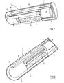
- the in the FIGS. 1 to 3 illustrated first embodiment of the sensor 1 has the shape of an elongated ampoule with the approximate dimensions of 2 mm in diameter and 8 mm in length, these data are variable within wide limits.
- the jacket 2 of the sensor 1 is formed by a semipermeable wall of cellulose, through which glucose can penetrate into the ampoule.
- the largest part of the interior of the sensor 1 is occupied by a cylindrical plastic part 3, which by several protruding on its jacket ribs 4 in Sensor 1 is centered and has an axial bore 5.
- the plastic part which is for example an injection molded part made of polycarbonate, serves on the one hand as a carrier for a vibrating member described below and on the other hand for reducing the volume of liquid in the sensor 1.
- the sensor is in the ready state with a sensitive high molecular weight liquid, for example dextran and ConA filled.
- a permanent magnet 6 is arranged in the sensor 1, which is over-injected to avoid corrosion with a plastic sheath 7 made of polycarbonate.
- the plastic casing 7, the casing 2 of the sensor 1 and the plastic part 3 are partially cut open to allow a view into the interior of the plastic part 3.
- the plastic sheath 7 serves as a support for a bending beam 8, for example, alumina ceramic, which extends along the plastic part 3.
- the plastic part 3 is flattened in the region of the bending beam 8 ( Fig. 3 ) and here carries a base substrate 9 in the form of a thin strip. Between the free end of the bending beam 8 and the base substrate 9, a spacer element 10 is provided, whose thickness is selected so that a sufficiently large vibration amplitude of the bending beam of about 100 microns is possible.
- Bending beam 8, base substrate 9 and spacer 10 are made of the same material and are produced by successive layers of laminates and subsequent packaging.
- the plastic sheath 7 carries on its the plastic part 3 facing end face a narrow., Elongated wing 11 which projects into the bore 5 of the plastic part 3.
- the permanent magnet 6 When the permanent magnet 6 is excited by an external oscillating magnetic field, it is set in vibration and with the vibration of the magnet 6 also vibrate the plastic sheath 7, the bending beam 8 and the wing 11.
- These vibrations have the fact that existing in the sensor 1 sensitive liquid is mixed with the glucose that has entered the sensor 1.
- the vibration of the blade 11 is of great importance for a rapid measurement because it simulates the flow in the sensor 1 and ensures a homogeneous glucose concentration in the sensor.
- the frequency of the magnet 6 exciting magnetic field is chosen so that it vibrates at a frequency in the range between 100 and 300 Hz. Bending beam 8 and wing 11 vibrate at the same frequency, wherein the vibration amplitude is about 100 microns or 0.1 mm. After the mixing of sensitive liquid and glucose, the magnetic field is switched off and the decay time of the vibration is measured, which is done on the basis of the magnetic field generated by the bending beam 8 with oscillating magnet 6.
- Fig. 4 shows a block diagram of the designated by the reference symbol B HMI device.
- This contains in particular a magnet 12 for generating a magnetic field 13 for the excitation of the magnet 6 in the ampoule 1 (FIG. Fig. 1 ) and a coil 14 for the excitation of the magnet 12, which also serve as a magnetic field sensor for detecting the magnetic field generated by the magnet 6 in the sensor 1, and a microprocessor 15.
- the coil 14 is on the one hand with a receiving amplifier 16 and on the other hand with a transmission amplifier 17 whose output or input is guided to the microprocessor 15.
- the microprocessor 15 is also connected to a display 18 for the currently measured glucose value and to a memory 19 for the storage of the glucose values.
- the operating unit B contains a not shown power supply.
- an additional magnetic field sensor for example a Hall sensor, can be provided for the exact positioning (normalization) of the operating device B relative to the sensor 1.
- Another possible solution for the functions excitation and detection of the HMI B is based on a rotating dipole, a hard disk motor with two permanent magnet excites the vibrations of the bending beam 8 from the outside and by analyzing the engine damping of the quality factor of the oscillator (bending beam 8 plus magnet 6 ) is determined.
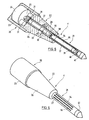
- the in the FIGS. 5 and 6 illustrated sensor 1 ' also has the shape of an elongated ampoule; he is different from the one in the FIGS. 1 to 3 represented sensor 1 essentially by the method of measuring the viscosity of the consisting of the sensitive liquid and glucose mixture. While the viscosity measurement in the sensor 1 is based on the vibration behavior of a vibrating member, it takes place in the second sensor 1 'on the basis of the rotational behavior of a measuring element. The rotational behavior of the measuring device is analyzed on the basis of its decay behavior after switching off the magnet. However, the measurement result becomes more accurate when two measuring organs are used, one of which rotates in the mixture of sensitive liquid and glucose and the other in a reference liquid.
- the reference liquid is formed by sensitive liquid.
- the sensor 1 has a rotationally symmetrical shape and consists of a cylindrical head part 20, a cylindrical measuring part 21 of smaller diameter the head part 20 has an approximate diameter of 2.5 mm and an approximate length of 3 mm, the measuring part 21 has an approximate diameter of 0.6 mm and an approximate length of 6 mm, and the reference part 22 also has an approximate length of about 6 mm.
- the head part 20 consists of an airtight housing 23, in which a drive magnet 24 is mounted.
- the drive magnet 16 is mechanically supported on two bearings 25, of which Fig. 5 only the bearing mounted in the reference part 22 front bearing is visible. The hidden by the drive magnet 24 rear of the bearing 25 is mounted on the housing 23.
- the reference part 22 comprises a frusto-conical housing 26 which has an axial bore in which an airtight, cylindrical reference chamber 27 is arranged.
- the frusto-conical housing 26 is connected to the head part 20 at its thicker end and to the measuring part 21 at its thinner end.
- a reference liquid preferably by the in the description of the FIGS. 1 to 3 said high molecular weight sensitive liquid is formed.
- a cylindrical reference member 28 is rotatably mounted in the reference chamber 27.
- the reference member 28 carries at its ends depending on a magnetic end portion 29 and 30, of which the end portion 29 forms a magnetic coupling with the drive magnet 24 and two protruding from this permanent magnet 31 and the end portion 30, a magnetic coupling with the measuring part 21. Between the two magnetic end portions 29 and 30, the reference member 28 carries a further permanent magnet 32, which is located in the level of a arranged in the housing 26 and the reference chamber 27 encompassing ring magnet 33. Ring magnet 33 and permanent magnet 32 serve to stabilize the reference member 28 in its axis of rotation. This stabilization can also be achieved by mechanical support of the axle.
- the measuring part 21 comprises a cylindrical housing 34, which is fastened at its one end in the reference part 22 and carries at its other end a termination part 22.
- the housing 34 forms a measuring chamber, in which said sensitive liquid is located, and in which a cylindrical measuring member 35 is also rotatably mounted.
- the shell of the housing 34 is provided with elongated windows 36 and lined inside with a semipermeable cellulose-formed membrane 37, through which glucose can penetrate into the measuring chamber.
- the result of the rotation of the measuring element 35 is that the sensitive liquid present in the measuring chamber is mixed with the glucose which has penetrated into it, which leads to a homogeneous glucose concentration in the measuring chamber.
- the measuring member 35 carries at its ends depending on a magnetic end portion 38 and 39, of which the reference member 28 adjacent end portion 38 for magnetic coupling with the Reference member 28 and thus used to drive the measuring element 35.
- the other end part 39 forms a magnetic coupling with a permanent magnet 40, which is fixed at the free end of the housing 34, and serves to stabilize the measuring member 35 in its axis of rotation.
- the reference numeral 41 designates a conical end part of the measuring part 21 of the sensor.
- the HMI device for in the FIGS. 5 and 6 illustrated second embodiment of the sensor is constructed substantially the same as that in Fig. 4 shown operating device B and differs from this mainly in that it contains a plurality of coils 14 for generating a rotating field, which sets the drive magnet 24 in rotation.
- the operating device has a plurality of magnetic field sensors which measure the rotation of the drive magnet 24 after switching off the magnetic rotary field.
- the drive magnet 24 drives via the magnets 31 and 29 the reference member 28 and this via the magnets 30 and 38, the measuring member 35.
- the measuring member 35 and the reference member 28 rotate in the housings 27 and 34, both the same sensitive liquid of high molecular weight contain.
- the housing 27 with the reference member 28 is sealed airtight and the housing 34 with the measuring member 35 is sealed with the semipermeable membrane 37 through which glucose can penetrate into the measuring chamber.
- the magnetic coupling between the reference member 28 (permanent magnet 30) and the measuring member 35 (permanent magnet 38) is designed so that the measuring member 35 rotates only up to a critical rotational frequency.
- the system measures the viscosity of the liquid in the housing 27 based on the decay of the rotation of the drive magnet 24 when the magnetic rotating field is switched off, and this liquid is exclusively the said sensitive liquid.
- the decay of the rotation of the drive magnet 24 when the magnetic rotating field is switched off is determined by the viscosity of the liquid mixture of sensitive liquid and glucose in the measuring chamber (housing 34). The glucose concentration determined from this information is independent of temperature, which is a significant advantage over a system without reference measurement.
- the drive magnet would directly drive the measuring element 35 via the permanent magnets 31 and 38.
- the in the FIGS. 1 to 3 shown Sensor.1 can be adapted by relatively simple modification for use as a Holtersystem in which the glucose content is continuously monitored under medical supervision and over a period of several days.
- the magnet 6 in the sensor 1 exciting magnetic field is not generated by an external magnet 12 but by a disposed inside the sensor 1 current coil, from which two thin electrical wires are passed through the skin of the patient to the outside to the control unit.
- the named current coil is preferably in the region of the spacer element 10 (FIG. Fig. 1 ) arranged.
- bending beam 8 and base substrate 9 are made of soft magnetic material.
- a current coil for the excitation of the drive magnet 24 could be arranged.
Landscapes
- Health & Medical Sciences (AREA)
- Life Sciences & Earth Sciences (AREA)
- Physics & Mathematics (AREA)
- Pathology (AREA)
- General Health & Medical Sciences (AREA)
- Engineering & Computer Science (AREA)
- Public Health (AREA)
- Animal Behavior & Ethology (AREA)
- Veterinary Medicine (AREA)
- Surgery (AREA)
- Medical Informatics (AREA)
- Molecular Biology (AREA)
- Biophysics (AREA)
- Biomedical Technology (AREA)
- Heart & Thoracic Surgery (AREA)
- General Physics & Mathematics (AREA)
- Immunology (AREA)
- Biochemistry (AREA)
- Analytical Chemistry (AREA)
- Chemical & Material Sciences (AREA)
- Computer Networks & Wireless Communication (AREA)
- Emergency Medicine (AREA)
- Optics & Photonics (AREA)
- Hematology (AREA)
- Measurement Of The Respiration, Hearing Ability, Form, And Blood Characteristics Of Living Organisms (AREA)
- Investigating Or Analysing Biological Materials (AREA)
- Investigating Or Analyzing Materials By The Use Of Electric Means (AREA)
- Investigating Or Analyzing Materials By The Use Of Magnetic Means (AREA)
Description
- Die Erfindung liegt auf dem Gebiet der Blutzucker-Messung durch einen implantierbaren Sensor. Diabetes mellitus (Zuckerkrankheit) ist eine der häufigsten chronischen Erkrankungen. Etwa 8% der US Bevölkerung sind betroffen und infolge zunehmendem Uebergewicht in der Bevölkerung steigt diese Zahl jährlich. Man rechnet weltweit mit gegen 300 Millionen Diabetikern bis im Jahre 2025. Eine langjährige und ungenügend behandelte Zuckerkrankheit bedeutet hohes Risiko für Herzinfarkt, Hirnschlag, Durchblutungsstörungen der unteren Extremitäten, Nierenschaden, Blindheit sowie Nervenleitungsstörungen, welche zu Amputationen der Füsse oder Beine führen können. Der Diabetes belastet deshalb das Gesundheitswesen mit ca. 10% aller Kosten.
- Durch verschiedene Studien wie der Diabetes Control and Complication Trial (DCCT) und die U. K. Prospective Diabetes Study (UKPDS) konnte gezeigt werden, dass durch eine verbesserte Blutzuckereinstellung das Risiko von Spätkomplikationen vermindert werden kann. Zur Blutzuckersenkung stehen verschiedene Behandlungsarten zur Verfügung: eine angepasste Ernährung, körperliche Betätigung, Tabletten und Insulin. Ein wesentliches Element, die Effizienz der jeweiligen Behandlung zu überprüfen ist die Blutzucker-Selbstmessung (Self- monitoring). Alle insulinabhängigen Diabetiker (Typ 1) und eine Auswahl von nicht insulin- abhängigen Diabetikern (Typ 2) sollten mehrmals täglich ihren Blutzucker messen. Bis heute geschieht dies durch einen Stich an der Fingerkuppe und Auftragen einer kleinen Blutmenge auf einen Teststreifen, welcher in ein Ablesegerät geschoben wird. Diese Art von Selbstmessung ist mit Schmerzen und hohen Kosten verbunden. Seit Jahren wird daher ein schmerzloses Verfahren zur kontinuierlichen Blutzuckermessung angestrebt. Möglichst viele Blutzuckermessungen sollten den Aerzten und Patienten erlauben, die Behandlungen laufend anzupassen und zu verbessern, wodurch das Risiko von Spätkomplikationen verringert und die Folgekosten gesenkt werden könnten.
- Die vorliegende Erfindung betrifft ein Sensorsystem für die Bestimmung der Glukose-Konzentration im Blut, mit einem implantierbaren Sensor und einem diesem zugeordneten Bediengerät.
- Dokument
GB-A-2 335 496 - Es ist ein transcutanes System mit einem implantierbaren Sensor bekannt, der eine Nadel aufweist, welche zwei durch einen Isolator getrennte verschiedene Metalle enthält, so dass ein elektrisches Potential angelegt werden kann. Der Sensor ist mit einem Monitor verbunden, der alle 5 Minuten über maximal 3 Tage die Glukosewerte aufzeichnet. Der Sensor ist nicht sehr stabil, so dass mehrmals täglich eine Eichung mit dem Blut des Patienten vorgenommen werden muss.
- Bei einem anderen heute auf dem Markt erhältlichen Messsystem zur Messung des Glukosegehalts wird durch Stromimpulse Glukose durch die Haut gezogen und in zwei Gel-Scheiben eines Sensors gesammelt, welcher den Glukosegehalt misst. Der Sensor, der auf der Rückseite eines uhrartigen Anzeigegeräts angeordnet ist, ist ein so genanntes minimal invasives System, das ist ein System, bei welchem man entweder etwas auf die Haut auftragen oder kleine Kanülen in diese stechen muss, wodurch ein Infektionsrisiko nicht ausgeschlossen werden kann. Aus diesem Grund muss bei diesem invasiven System der Sensor alle paar Tage gewechselt werden, ausserdem erfordert auch dieses System eine Eichung mit dem Blut des Patienten. Beide genannten bekannten Systeme werden auch als Holtersysteme bezeichnet, darunter versteht man Systeme für den Gebrauch durch einen Arzt und nicht durch den Patienten selbst.
- Durch die Erfindung soll ein Sensorsystem angegeben werden, welches für den Gebrauch durch den Patienten geeignet ist und diesem eine ständige Überwachung des Glukosegehalts seines Blutes ermöglichen soll, ohne dass nach der Implantation des Sensors schon nach kurzer Zeit ein neuerlicher Eingriff erforderlich ist, oder ein Infektionsrisiko darstellende Manipulationen an oder in der Haut des Patienten erforderlich sind.
- Die gestellte Aufgabe wird erfindungsgemäss dadurch gelöst, dass der Sensor die Form einer Ampulle aufweist, in welcher eine sensitive Flüssigkeit eingeschlossen ist und in welche Glukose eindringen kann, dass eine Messung der Viskosität des aus der sensitiven Flüssigkeit und der Glukose bestehenden Gemisches erfolgt, und dass das Bediengerät durch ein aussen auf der Haut zu tragendes, portables Gerät gebildet ist, wobei die Steuerung der Messung und deren Auswertung durch das Bediengerät erfolgt.
- Beim erfindungsgemässen Sensorsystem erfolgt durch das Bediengerät keinerlei Manipulation an oder in der Haut, so dass jede Reiz- und Infektionsgefahr ausgeschlossen ist. Der Sensor kann zumindest mehrere Monate lang implantiert sein, ohne dass eine Nacheichung oder dergleichen erforderlich wäre und dem Patienten bleiben die lästigen Blutabnahmen erspart. Der Patient kann jederzeit ohne irgendwelche Beschwerden den Glukosegehalt seines Blutes prüfen und diesen durch Einnahme entsprechender Medikamente regulieren, ohne dass eine Überwachung durch einen Arzt erforderlich wäre.
- Eine erste bevorzugte Ausführungsform des erfindungsgemässen Sensorsystems ist dadurch gekennzeichnet, dass die Messung der Viskosität anhand des Schwingverhaltens eines im Sensor angeordneten Schwingorgans erfolgt, welches durch ein oszillierendes Magnetfeld zu Schwingungen anregbar ist, wobei des Schwingverhalten des Schwingorgans anhand von dessen Abklingverhalten nach Abschalten des Magneten analysiert wird. Das Schwingorgan selbst erzeugt ein Magnetfeld, welches vom Bediengerät gemessen wird. Vorteilhafte Weiterbildungen dieser ersten bevorzugten Ausführungsform des erfindungsgemässen Sensorsystems sind in den Ansprüchen 2 bis 9 beansprucht.
- Eine zweite bevorzugte Ausführungsform des erfindungsgemässen Sensorsystems ist dadurch gekennzeichnet, dass die Messung der Viskosität anhand der Rotation eines im Sensor angeordneten Messorgans erfolgt, welches von einem ebenfalls im Sensor angeordneten Antriebsmagneten antreibbar ist, wobei die Rotation des Messorgans anhand von deren Abklinghalten nach Abschalten des Antriebsmagneten analysiert wird.
- Vorzugsweise ist der Sensor zweistufig aufgebaut und weist ein Kopfteil und ein Messteil auf, wobei das Kopfteil den Antriebsmagneten und das Messteil das Messorgan enthält und der Antriebsmagnet gegen Flüssigkeit abgeschirmt in einem Gehäuse angeordnet ist.
- Eine dritte bevorzugte Ausführungsform des erfindungsgemässen Sensorsystems ist dadurch gekennzeichnet, dass zwischen Kopfteil und Messteil ein die beiden verbindendes Referenzteil vorgesehen ist, welches eine gegen Flüssigkeit abgedichtete Kammer aufweist, welche ein rotierbar gelagertes Referenzorgan und die genannte sensitive Flüssigkeit enthält. Mittels des Referenzteils wird die Genauigkeit der Messung erhöht und die Einflüsse von Temperaturänderungen auf das Messresultat werden reduziert.
- Vorteilhafte Weiterbildungen der zweiten und/oder dritten bevorzugten Ausführungsform sind in den Ansprüchen 10 bis 20 beansprucht.
- Im Folgenden wird die Erfindung anhand eines Ausführungsbeispiels und der Zeichnungen näher erläutert; es zeigt:
- Fig. 1, 2
- je eine perspektivische Darstellung eines ersten Ausführungsbeispiels des teilweise aufgeschnittenen Sensors eines erfindungsgemässen Sensorsystems,
- Fig. 3
- einen Querschnitt durch den Sensor von
Fig. 1, 2 ; - Fig. 4
- ein Blockschema des Bediengeräts des erfindungsgemässen Sensorsystems;
- Fig. 5
- eine perspektivische Darstellung eines zweiten Ausführungsbeispiels des teilweise aufgeschnittenen Sensors eines erfindungsgemässen Sensorsystems; und
- Fig. 6
- eine perspektivische Ansicht des Sensors von
Fig. 5 im geschlossenen Zustand. - Der in den
Figuren 1 bis 3 dargestellte erste Ausführungsbeispiel des Sensors 1 hat die Form einer länglichen Ampulle mit den ungefähren Dimensionen von 2 mm Durchmesser und 8 mm Länge, wobei diese Angaben in weiten Grenzen variabel sind. Der Mantel 2 des Sensors 1 ist durch eine semipermeable Wand aus Cellulose gebildet, durch welche Glukose in die Ampulle eindringen kann. Der grösste Teil des Innenraums des Sensors 1 wird von einem zylindrischen Kunststoffteil 3 eingenommen, das durch mehrere an seinem Mantel abstehende Rippen 4 im Sensor 1 zentriert ist und eine axiale Bohrung 5 aufweist. Das Kunststoffteil, das beispielsweise ein aus Polycarbonat hergestelltes Spritzgussteil ist, dient einerseits als Träger für ein weiter unten beschriebenes Schwingorgan und anderseits zur Verkleinerung des Flüssigkeitsvolumens im Sensor 1. Der Sensor ist im betriebsbereiten Zustand mit einer sensitiven Flüssigkeit mit hohem Molekulargewicht, beispielsweise Dextran und ConA gefüllt. - Im Anschluss an das in den
Fig. 1 und 2 rechte Ende des Kunststoffteils 3 ist im Sensor 1 ein Permanentmagnet 6 angeordnet, der zur Vermeidung von Korrosion mit einer Kunststoffummantelung 7 aus Polycarbonat überspritzt ist. In denFig. 1 und 2 sind die Kunststoffummantelung 7, der Mantel 2 des Sensors 1 und das Kunststoffteil 3 teilweise aufgeschnitten, um einen Blick ins Innere des Kunststoffteils 3 zu ermöglichen. Die Kunststoffummantelung 7 dient als Träger für einen Biegebalken 8 aus beispielsweise Aluminiumoxidkeramik, der sich entlang des Kunststoffteils 3 erstreckt. Das Kunststoffteil 3 ist im Bereich des Biegebalkens 8 abgeflacht (Fig. 3 ) und trägt hier ein Basissubstrat 9 in Form eines dünnen Streifens. Zwischen dem freien Ende des Biegebalkens 8 und dem Basissubstrat 9 ist ein Distanzelement 10 vorgesehen, dessen Dicke so gewählt ist, dass eine genügend grosse Schwingungsamplitude des Biegebalkens von etwa 100 µm möglich ist. - Biegebalken 8, Basissubstrat 9 und Distanzelement 10 bestehen aus dem gleichen Material und sind durch aufeinander Schichten von Laminaten und anschliessendes Verpacken hergestellt. Die Kunststoffummantelung 7 trägt an ihrer dem Kunststoffteil 3 zugewandten Stirnfläche einen schmalen., langgestreckten Flügel 11, der in die Bohrung 5 des Kunststoffteils 3 ragt. Wenn der Permanentmagnet 6 von einem externen oszillierenden Magnetfeld erregt wird, wird er in Vibrationen versetzt und mit der Vibration des Magneten 6 vibrieren auch die Kunststoffummantelung 7, der Biegebalken 8 und der Flügel 11. Diese Vibrationen haben zur Folge, dass die im Sensor 1 vorhandene sensitive Flüssigkeit mit der in den Sensor 1 eingedrungenen Glukose vermischt wird. Dabei ist die Vibration des Flügels 11 von grosser Bedeutung für eine schnelle Messung, weil sie den Fluss im Sensor 1 simuliert und für eine homogene Glukosekonzentration im Sensor sorgt.
- Die Frequenz des den Magneten 6 erregenden Magnetfeldes ist so gewählt, dass dieser mit einer Frequenz im Bereich zwischen 100 und 300 Hz vibriert. Biegebalken 8 und Flügel 11 vibrieren mit der gleichen Frequenz, wobei die Schwingungsamplitude etwa 100 µm oder 0.1 mm beträgt. Nach der Durchmischung von sensitiver Flüssigkeit und Glukose wird das Magnetfeld abgeschaltet und die Abklingzeit der Vibration gemessen, was anhand des von dem mit dem Biegebalken 8 mit schwingenden Magneten 6 erzeugten Magnetfeldes erfolgt.
- Die Viskositätsänderung von Dextran und ConA in einer physiologisch salinen Lösung in Funktion der Glukose-Konzentration ist in R. Ehwald et al., "Viscosimetric affinity assay", Anal Biochem 234,1 (1996) und U. Beyer, "Recording of subcutaneous glucose dynamics by a viscosimetric affinity sensor", Diabetologia 44, 416 (2001) beschrieben. Die dort beschriebene Lösung basiert auf der Zirkulation der sensitiven Flüssigkeit durch ein aus mehreren Komponenten bestehendes System. Beim erfindungsgemässen System wird die Viskosität direkt im Volumen der im Sensor 1 eingeschlossenen sensitiven Flüssigkeit gemessen, wobei der Sensor in Längsrichtung senkrecht zur Körperoberfläche so unter die Haut implantiert wird, dass das in den
Fig. 1 und 2 flache rechte Ende des Sensors 1 etwa 2 mm unterhalb der Haut liegt. Die Implantation erfolgt beispielsweise in Gürtelhöhe mit einer Injektionsnadel. -
Fig. 4 zeigt ein Blockschema des mit dem Bezugszeichen B bezeichneten Bediengeräts. Dieses enthält insbesondere einen Magneten 12 zur Erzeugung eines Magnetfeldes 13 für die Erregung des Magneten 6 in der Ampulle 1 (Fig. 1 ) und eine Spule 14 für die Erregung des Magneten 12, welche gleichzeitig auch als Magnetfeldsensor für die Detektion des vom Magneten 6 im Sensor 1 erzeugten Magnetfeldes dienen, und einen Mikroprozessor 15. Die Spule 14 ist einerseits mit einem Empfangsverstärker 16 und andererseits mit einem Sendeverstärker 17 verbunden, deren Aus- bzw. Eingang an den Mikroprozessor 15 geführt ist. Der Mikroprozessor 15 ist ausserdem mit einer Anzeige 18 für den aktuell gemessenen Glukosewert und mit einem Speicher 19 für die Speicherung der Glukosewerte verbunden. Ausserdem enthält das Bediengerät B eine nicht eingezeichnete Stromversorgung. Optional kann ein zusätzlicher Magnetfeldsensor, beispielsweise ein Hall-Sensor, für die genaue Positionierung (Normalisierung) des Bediengeräts B relativ zum Sensor 1 vorgesehen sein. - Eine andere mögliche Lösung für die Funktionen Anregung und Detektion des Bediengeräts B beruht auf einem rotierenden Dipol, wobei ein Harddisk-Motor mit zwei Permanentmagneten die Schwingungen des Biegebalkens 8 von aussen anregt und durch Analyse der Motordämpfung der Gütefaktor des Oszillators (Biegebalken 8 plus Magnet 6) ermittelt wird.
- Der in den
Figuren 5 und 6 dargestellte Sensor 1' hat ebenfalls die Form einer länglichen Ampulle; er unterscheidet sich von dem in denFiguren 1 bis 3 dargestellten Sensor 1 im wesentlichen durch die Methode der Messung der Viskosität des aus der sensitiven Flüssigkeit und der Glukose bestehenden Gemisches. Während die Viskositätsmessung beim Sensor 1 anhand des Schwingverhaltens eines Schwingorgans erfolgt, erfolgt sie beim zweiten Sensor 1' anhand des Rotationsverhaltens eines Messorgans. Dabei wird das Rotationsverhalten des Messorgans anhand von dessen Abklingverhalten nach Abschalten des Magneten analysiert. Das Messergebnis wird jedoch genauer, wenn zwei Messorgane verwendet werden, von denen das eine in dem aus sensitiver Flüssigkeit und Glukose bestehendem Gemisch und das andere in einer Referenzflüssigkeit rotiert. Vorzugsweise ist die Referenzflüssigkeit durch sensitive Flüssigkeit gebildet. - Gemäss den
Figuren 5 und 6 hat der Sensor 1' eine rotationssymmetrische Form und besteht aus einem zylindrischen Kopfteil 20, einem zylindrischen Messteil 21 von geringerem Durchmesser als das Kopfteil 20, und einem Kopfteil 20 und Messteil 21 verbindenden konischen Referenzteil 22. Das Kopfteil 20 hat einen ungefähren Durchmesser von 2.5 mm und eine ungefähre Länge von 3 mm, das Messteil 21 hat einen ungefähren Durchmesser von 0.6 mm und eine ungefähre Länge von 6 mm, und das Referenzteil 22 hat ebenfalls eine ungefähre Länge von etwa 6 mm. Das Kopfteil 20 besteht aus einem luftdichten Gehäuse 23, in welchem ein Antriebsmagnet 24 gelagert ist. Der Antriebsmagnet 16 ist auf zwei Lagern 25 mechanisch abgestützt, von denen ausFig. 5 nur das im Referenzteil 22 gelagerte vordere Lager ersichtlich ist. Das durch den Antriebsmagneten 24 verdeckte hintere der Lager 25 ist am Gehäuse 23 gelagert. - Das Referenzteil 22 umfasst ein kegelstumpfförmiges Gehäuse 26, welches eine axiale Bohrung aufweist, in der eine luftdichte, zylindrische Referenzkammer 27 angeordnet ist. Das kegelstumpfförmiger Gehäuse 26 ist an seinem dickeren Ende mit dem Kopfteil 20 und an seinem dünneren Ende mit dem Messteil 21 verbunden. In der Referenzkammer 27 befindet sich eine Referenzflüssigkeit, die vorzugsweise durch die in der Beschreibung der
Figuren 1 bis 3 genannte sensitive Flüssigkeit mit hohem Molekulargewicht gebildet ist. Ausserdem ist in der Referenzkammer 27 ein zylindrisches Referenzorgan 28 drehbar gelagert. - Das Referenzorgan 28 trägt an seinen Enden je ein magnetisches Endteil 29 und 30, von denen das Endteil 29 eine magnetische Kopplung mit dem Antriebsmagneten 24 und zwei vom diesem abstehenden Permanentmagneten 31 und das Endteil 30 eine magnetische Kopplung mit dem Messteil 21 bildet. Zwischen den beiden magnetischen Endteilen 29 und 30 trägt das Referenzorgan 28 einen weiteren Permanentmagneten 32, der sich im Niveau eines im Gehäuse 26 angeordneten und die Referenzkammer 27 umgreifenden Ringmagneten 33 befindet. Ringmagnet 33 und Permanentmagnet 32 dienen zur Stabilisierung des Referenzorgans 28 in seiner Rotationsachse. Diese Stabilisierung kann auch durch eine mechanische Lagerung der Achse erreicht werden.
- Das Messteil 21 umfasst ein zylindrisches Gehäuse 34, welches an seinem einen Ende im Referenzteil 22 befestigt ist und an seinem anderen Ende ein Abschlussteil 22 trägt. Das Gehäuse 34 bildet eine Messkammer, in der sich die genannte sensitive Flüssigkeit befindet, und in der ausserdem ein zylindrisches Messorgan 35 drehbar gelagert ist. Der Mantel des Gehäuses 34 ist mit länglichen Fenstern 36 versehen und innen mit einer semipermeablen, aus Cellulose gebildeten Membran 37 ausgekleidet, durch welche Glukose in die Messkammer eindringen kann. Die Rotation des Messorgans 35 hat zur Folge, dass die in der Messkammer vorhandene sensitive Flüssigkeit mit der in diese eingedrungenen Glukose vermischt wird, was zu homogenen Glukosekonzentration in der Messkammer führt.
- Das Messorgan 35 trägt an seinen Enden je ein magnetisches Endteil 38 und 39, von denen das dem Referenzorgan 28 benachbarte Endteil 38 zur magnetischen Kopplung mit dem Referenzorgan 28 und damit zum Antrieb des Messorgans 35 dient. Das andere Endteil 39 bildet eine magnetische Kopplung mit einem Permanentmagneten 40, der am freien Ende des Gehäuses 34 fixiert ist, und dient zur Stabilisierung des Messorgans 35 in seiner Rotationsachse. Mit dem Bezugszeichen 41 ist ein kegelförmiges Abschlussteil des Messteils 21 des Sensors bezeichnet.
- Das Bediengerät für das in den
Fig. 5 und 6 dargestellte zweite Ausführungsbeispiel des Sensors ist im Wesentlichen gleich aufgebaut wie das inFig. 4 dargestellte Bediengerät B und unterscheidet sich von diesem hauptsächlich dadurch, dass es mehrere Spulen 14 für die Erzeugung eines Drehfeldes enthält, welches den Antriebsmagneten 24 in Rotation versetzt. Analog weist das Bediengerät mehrere Magnetfeldsensoren auf, welche die Rotation des Antriebsmagneten 24 nach dem Abschalten des magnetischen Drehfeldes messen. - Der Antriebsmagnet 24 treibt über die Magneten 31 und 29 das Referenzorgan 28 an und dieses über die Magneten 30 und 38 das Messorgan 35. Das Messorgan 35 und das Referenzorgan 28 rotieren in den Gehäusen 27 und 34, die beide die gleiche sensitive Flüssigkeit von hohem Molekulargewicht enthalten. Das Gehäuse 27 mit dem Referenzorgan 28 ist luftdicht abgedichtet und das Gehäuse 34 mit dem Messorgan 35 ist mit der semipermeablen Membran 37 abgedichtet, durch welche Glukose in die Messkammer eindringen kann. Die magnetische Kopplung zwischen dem Referenzorgan 28 (Permanentmagnet 30) und dem Messorgan 35 (Permanentmagnet 38) ist so ausgelegt, dass das Messorgan 35 nur bis zu einer kritischen Rotationsfrequenz mitdreht.
- Oberhalb dieser kritischen Frequenz misst das System anhand des Abklingens der Rotation des Antriebsmagneten 24 bei Abschaltung des magnetischen Drehfeldes die Viskosität der Flüssigkeit im Gehäuse 27, und diese Flüssigkeit ist ausschliesslich die genannte sensitive Flüssigkeit. Unterhalb der kritischen Frequenz ist das Abklingen der Rotation des Antriebsmagneten 24 bei Abschaltung des magnetischen Drehfeldes durch die Viskosität des Flüssigkeitsgemisches aus sensitiver Flüssigkeit und Glukose in der Messkammer (Gehäuse 34) bestimmt. Die anhand dieser Informationen bestimmte Glukosekonzentration ist von der Temperatur unabhängig, was einen wesentlichen Vorteil gegenüber einem System ohne Referenzmessung darstellt.
- Wenn dieser Vorteil nicht gewünscht wird oder nicht wesentlich ist, kann der in den
Figuren 5 und 6 dargestellte Sensor durch Weglassen des Referenzteils 22 vereinfacht werden. Der Antriebsmagnet würde in diesem Fall über die Permanentmagnete 31 und 38 das Messorgan 35 direkt antreiben. - Der in den
Figuren 1 bis 3 dargestellte Sensor.1 kann durch relativ einfache Modifikation für die Anwendung als Holtersystem adaptiert werden, bei welchem der Glukosegehalt unter ärztlicher Aufsicht und über einen Zeitraum von mehreren Tagen kontinuierlich überwacht wird. Bei dieser Anwendung wird das den Magneten 6 im Sensor 1 erregende Magnetfeld nicht von einem externen Magneten 12 sondern durch eine im Inneren des Sensors 1 angeordnete Stromspule erzeugt, von welcher zwei dünne elektrische Drähte durch die Haut des Patienten nach aussen zum Bediengerät geführt sind. Die genannte Stromspule ist vorzugsweise im Bereich des Distanzelements 10 (Fig. 1 ) angeordnet. Um einen ausreichenden Magnetfluss von der Stromspule zum Magneten 6 zu gewährleisten, bestehen Biegebalken 8 und Basissubstrat 9 aus weichmagnetischem Material. Gleiches gilt für den in denFiguren 5 und 6 dargestellten Sensor 1', wo ebenfalls im Inneren des Gehäuses 23 eine Stromspule für die Erregung des Antriebsmagneten 24 angeordnet werden könnte.
Claims (20)
- Sensorsystem für die Bestimmung der Glukose-Konzentration im Blut, mit einem implantierbaren Sensor (1, 1') und einem diesem zugeordneten Bediengerät (B), wobei der Sensor (1, 1') die Form einer Ampulle aufweist, in welcher eine sensitive Flüssigkeit eingeschlossen ist und in welche Glukose eindringen kann wobei der Sensor (1,1') eine Messung der Viskosität des aus der sensitiven Flüssigkeit und der Glukose bestehenden Gemisches vornimmt, und wobei das Bediengerät (B) durch ein aussen auf der Haut zu tragendes, portables Gerät gebildet ist, wobei die Steuerung der Messung und deren Auswertung durch das Bediengerät (B) erfolgt, dadurch gekennzeichnet dass die Messung der Viskosität anhand des Schwingverhaltens eines im Sensor (1) angeordneten Schwingorgans (8) erfolgt, welches durch ein oszillierendes Magnetfeld zu Schwingungen anregbar ist, und dass das Schwingverhalten des Schwingorgans (8) anhand von dessen Abklingverhalten nach Abschalten des Magneten (6) analysiert wird, wobei das Schwingorgan (8) selbst ein Magnetfeld erzeugt, welches vom Bediengerät gemessen wird.
- Sensorsystem nach Anspruch 1, dadurch gekennzeichnet, dass durch das Schwingorgan zusätzlich eine Homogenisierung der Flüssigkeit im Sensor (1) erfolgt.
- Sensorsystem nach Anspruch 2, dadurch gekennzeichnet, dass das Schwingorgan (8) formschlüssig mit dem Magneten (6) verbunden und durch einen Biegebalken gebildet ist.
- Sensorsystem nach Anspruch 3, dadurch gekennzeichnet, dass der Magnet (6) an einem der beiden Enden des Biegebalkens angebracht und durch ein Magnetfeld (13) in Schwingungen versetzbar ist.
- Sensorsystem nach Anspruch 4, dadurch gekennzeichnet, dass das genannte Magnetfeld (13) durch eine im Bediengerät (B) vorgesehene elektromagnetische Anordnung oder durch eine im Sensor (1) vorgesehene elektrische Spule erzeugt wird.
- Sensorsystem nach einem der Ansprüche 1 bis 5, dadurch gekennzeichnet, dass der Sensor (1) eine das Eindringen von Glukose ermöglichende semipermeable Wand (2) aufweist.
- Sensorsystem nach einem der Ansprüche 1 bis 6, gekennzeichnet durch ein im Sensor (1) angeordnetes, diesen teilweise ausfüllendes und damit das Flüssigkeitsvolumen begrenzendes Kunststoffteil (3), welches als Auflage für das Schwingorgan (8) ausgebildet ist und eine längliche Bohrung (5) aufweist, in welche ein am Magneten (6) angeordneter und zur Durchmischung der Flüssigkeiten vorgesehener Flügel (11) ragt.
- Sensorsystem nach Anspruch 5, dadurch gekennzeichnet, dass die genannte elektro- magnetische Anordnung Mittel zur Erregung des Magneten (6) im Sensor (1) und einen Magnetfeldsensor für das von diesem Magneten erzeugte Magnetfeld enthält.
- Sensorsystem nach Anspruch 8, dadurch gekennzeichnet, dass die genannten Mittel und der genannte Magnetfeldsensor durch einen Magneten (12) und eine diesen erregende Spule (14) sowie einen mit der Spule (14) verbundenen Mikroprozessor (15) gebildet sind.
- Sensorsystem für die Bestimmung der Glukose-Konzentration im Blut, mit einem implantierbaren Sensor (1, 1') und einem diesem zugeordneten Bediengerät (B), wobei der Sensor (1, 1') die Form einer Ampulle aufweist, in welche eine sensitive Flüssigkeit eingeschlossen ist und in welche Glukose eindringen kann, wobei der Sensor (1,1') eine Messung der Viskosität des aus der sensitiven Flüssigkeit und der Glukose bestehenden Gemisches vornimmt, und wobei das Bediengerät (B) durch ein aussen auf der Haut zu tragendes, portables Gerät gebildet ist, wobei die Steuerung der Messung und deren Auswertung durch das Bediengerät (B) erfolgt, dadurch gekennzeichnet, dass die Messung der Viskosität anhand der Rotation eines im Sensor (1') angeordneten Messorgans (35) erfolgt, welches von einem ebenfalls im Sensor (1') angeordneten Antriebsmagneten (24) antreibbar ist und dass die Rotation des Messorgans (35) anhand von deren Abklingverhalten nach Abschalten des Antriebsmagneten (24) analysiert wird.
- Sensorsystem nach Anspruch 10, dadurch gekennzeichnet, dass der Sensor (1') zweistufig aufgebaut ist und ein Kopfteil (20) und ein Messteil (21) aufweist, wobei das Kopfteil (20) den Antriebsmagneten (24) und das Messteil (21) das Messorgan (35) enthält und der Antriebsmagnet (24) gegen Flüssigkeit abgeschirmt und in einem Gehäuse (23) angeordnet ist.
- Sensorsystem nach Anspruch 11, dadurch gekennzeichnet, dass zwischen Kopfteil (20) und Messteil (21) ein die beiden verbindendes Referenzteil (22) vorgesehen ist, welches eine gegen Flüssigkeit abgedichtete Kammer (27) aufweist, welche ein rotierbar gelagertes Referenzorgan (28) und die genannte sensitive Flüssigkeit enthält.
- Sensorsystem nach Anspruch 11 oder 12, dadurch gekennzeichnet, dass das Kopfteil (20) und das Messteil (21) je ein zylindrische Form aufweisen, wobei der Durchmesser des Kopfteils (20) grösser ist als derjenige des Messteils (21).
- Sensorsystem nach den Ansprüchen 12 und 13, dadurch gekennzeichnet, dass das Referenzteil (22) die Form eines Kegelstumpfes aufweist, und dass das Referenzorgan (28) und das Messorgan (35) als längliche Zylinder ausgebildet sind.
- Sensorsystem nach Anspruch 14, dadurch gekennzeichnet, dass das Messteil (21) als längliches Gehäuse (34) ausgebildet ist, welches fensterartige Öffnungen (36) aufweist und innen mit einer das Eindringen von Glukose ermöglichenden semipermeablen Folie (37) ausgekleidet ist.
- Sensorsystem nach Anspruch 15, dadurch gekennzeichnet, dass der Antriebsmagnet (24) durch ein Magnetfeld in Rotation versetzbar ist, welches von einer im Bediengerät (B) vorgesehenen elektromagnetischen Anordnung erzeugt wird.
- Sensorsystem nach Anspruch 16, dadurch gekennzeichnet, dass der Antrieb des Messorgans (35) über magnetische Kopplungen (29,31 ; 30,38) zwischen dem Antriebsmagneten (24) und dem Referenzorgan (28) beziehungsweise zwischen dem Referenzorgan (28) und dem Messorgan (35) erfolgt.
- Sensorsystem nach Anspruch 17, dadurch gekennzeichnet, dass die magnetische Kopplung (30,38) zwischen Referenzorgan (28) und Messorgan (35) so ausgelegt ist, dass das Messorgan (35) nur bis zu einer bestimmten kritischen Rotationsfrequenz mitdreht.
- Sensorsystem nach Anspruch 18, dadurch gekennzeichnet, dass nach Abschalten des Antriebs des Antriebsmagneten (24) das Abklingen von dessen Rotation oberhalb der kritischen Rotationsfrequenz ausschliesslich durch die Viskosität der sensitiven Flüssigkeit in der Kammer (27) des Referenzteils (22) und unterhalb der kritischen Rotationsfrequenz durch die Viskosität des Gemisches aus sensitiver Flüssigkeit und Glukose im Gehäuse (34) des Messteils (21) bestimmt ist.
- Sensorsystem nach Anspruch 19, dadurch gekennzeichnet, dass anhand der beiden Viskositätswerte oberhalb und unterhalb der kritischen Rotationsfrequenz die Bestimmung eines von der Temperatur unabhängigen Werts der Glukosekonzentration erfolgt.
Priority Applications (1)
| Application Number | Priority Date | Filing Date | Title |
|---|---|---|---|
| EP03750231A EP1555933B1 (de) | 2002-10-28 | 2003-10-22 | Sensorsystem für die bestimmung der glukose-konzentration im blut |
Applications Claiming Priority (6)
| Application Number | Priority Date | Filing Date | Title |
|---|---|---|---|
| EP02024022A EP1415590A1 (de) | 2002-10-28 | 2002-10-28 | Glukose-Sensor |
| EP02024022 | 2002-10-28 | ||
| CH887032003 | 2003-05-16 | ||
| CH00887/03A CH696259A5 (de) | 2002-10-28 | 2003-05-16 | Sensorsystem für die Bestimmumg der Glukose-Konzentration im Blut. |
| EP03750231A EP1555933B1 (de) | 2002-10-28 | 2003-10-22 | Sensorsystem für die bestimmung der glukose-konzentration im blut |
| PCT/CH2003/000684 WO2004037079A1 (de) | 2002-10-28 | 2003-10-22 | Sensorsystem für die bestimmung der glukose-konzentration im blut |
Publications (2)
| Publication Number | Publication Date |
|---|---|
| EP1555933A1 EP1555933A1 (de) | 2005-07-27 |
| EP1555933B1 true EP1555933B1 (de) | 2009-10-07 |
Family
ID=32178138
Family Applications (2)
| Application Number | Title | Priority Date | Filing Date |
|---|---|---|---|
| EP02024022A Withdrawn EP1415590A1 (de) | 2002-10-28 | 2002-10-28 | Glukose-Sensor |
| EP03750231A Expired - Lifetime EP1555933B1 (de) | 2002-10-28 | 2003-10-22 | Sensorsystem für die bestimmung der glukose-konzentration im blut |
Family Applications Before (1)
| Application Number | Title | Priority Date | Filing Date |
|---|---|---|---|
| EP02024022A Withdrawn EP1415590A1 (de) | 2002-10-28 | 2002-10-28 | Glukose-Sensor |
Country Status (16)
| Country | Link |
|---|---|
| US (1) | US7789829B2 (de) |
| EP (2) | EP1415590A1 (de) |
| JP (1) | JP2006503678A (de) |
| KR (1) | KR20050055043A (de) |
| CN (1) | CN100423684C (de) |
| AT (1) | ATE444706T1 (de) |
| AU (1) | AU2003269666B2 (de) |
| BR (1) | BR0306653A (de) |
| CA (1) | CA2503896C (de) |
| CH (1) | CH696259A5 (de) |
| DE (1) | DE50312007D1 (de) |
| NO (1) | NO20052596L (de) |
| PL (1) | PL374945A1 (de) |
| TN (1) | TNSN04093A1 (de) |
| WO (1) | WO2004037079A1 (de) |
| YU (1) | YU47204A (de) |
Families Citing this family (14)
| Publication number | Priority date | Publication date | Assignee | Title |
|---|---|---|---|---|
| CN101282684B (zh) * | 2005-10-11 | 2011-05-25 | 皇家飞利浦电子股份有限公司 | 用于可植入装置的独立激活传感器 |
| DE102007008509B4 (de) | 2007-02-21 | 2008-12-24 | Humboldt-Universität Zu Berlin | Verfahren zur Messung der Viskosität und viskosimetrischer Affinitätssensor |
| EP2055369A1 (de) * | 2007-10-30 | 2009-05-06 | Sensile Pat AG | Permeable, sensitiv beschichtete Membran |
| EP2339955B1 (de) | 2008-07-14 | 2012-09-05 | École Polytechnique Fédérale de Lausanne (EPFL) | Viskosimetrischer biosensor zur überwachung von analytenkonzentrationen |
| EP2236077A1 (de) * | 2009-03-31 | 2010-10-06 | Sensile Pat AG | Medizinische Vorrichtung zum Messen einer Analytkonzentration |
| CN101566549B (zh) * | 2009-05-27 | 2011-07-20 | 重庆天海医疗设备有限公司 | 血液粘度测量装置的取样/测量针 |
| ES2388846B2 (es) * | 2011-03-21 | 2013-06-04 | Universidad De Huelva | Dispositivo para la medida de propiedades reológicas y seguimiento de procesos a presión. |
| CN103519828B (zh) * | 2013-11-04 | 2015-04-29 | 理康互联科技(北京)有限公司 | 分析物检测系统及其传感标签 |
| US10004433B2 (en) * | 2014-07-07 | 2018-06-26 | Verily Life Sciences Llc | Electrochemical sensor chip |
| KR101881632B1 (ko) * | 2015-11-10 | 2018-07-24 | 이인한 | 최소 침습 연속 혈당 측정 장치 |
| CA3005831A1 (en) * | 2015-11-20 | 2017-05-26 | Duke University | Glucose biosensors and uses thereof |
| CN105854685B (zh) * | 2016-06-15 | 2018-10-12 | 浙江大学 | 一种动态细胞打印微混合器 |
| EP3382370A1 (de) * | 2017-03-30 | 2018-10-03 | University Of Oulu | Sondenanordnung und verfahren für rheometrische messungen mit einer wegwerfsonde und fernlesbarkeit |
| KR102279341B1 (ko) * | 2019-07-23 | 2021-07-20 | 한국과학기술원 | 진동 특성의 변화를 이용한 비침습적 생체지표 측정 방법 및 장치 |
Family Cites Families (14)
| Publication number | Priority date | Publication date | Assignee | Title |
|---|---|---|---|---|
| DD252438A1 (de) * | 1986-08-08 | 1987-12-16 | Medizin Labortechnik Veb K | Rotationsviskosimeter |
| NL9200207A (nl) * | 1992-02-05 | 1993-09-01 | Nedap Nv | Implanteerbare biomedische sensorinrichting, in het bijzonder voor meting van de glucoseconcentratie. |
| DE4334834A1 (de) * | 1993-10-13 | 1995-04-20 | Andrzej Dr Ing Grzegorzewski | Biosensor zum Messen von Viskositäts- und/oder Dichteänderungen |
| US5547049A (en) * | 1994-05-31 | 1996-08-20 | Lord Corporation | Magnetorheological fluid composite structures |
| DE19501159B4 (de) * | 1995-01-06 | 2004-05-13 | Ehwald, Rudolf, Prof. Dr.sc.nat. | Mikrosensor zur Bestimmung der Konzentration von Glukose und anderen Analyten in Flüssigkeiten auf der Basis der Affinitätsviskosimetrie |
| US5743262A (en) * | 1995-06-07 | 1998-04-28 | Masimo Corporation | Blood glucose monitoring system |
| DE19714087C2 (de) * | 1997-04-07 | 2000-06-21 | Rudolph Ehwald | Verfahren zur Affinitätsviskosimetrie und viskosimetrischer Affinitätssensor |
| GB2335496B (en) * | 1998-03-20 | 2000-06-07 | David Eglise | Sensing devices & systems |
| US6271044B1 (en) * | 1998-05-06 | 2001-08-07 | University Of Pittsburgh Of The Commonwealth System Of Higher Education | Method and kit for detecting an analyte |
| US6201980B1 (en) * | 1998-10-05 | 2001-03-13 | The Regents Of The University Of California | Implantable medical sensor system |
| US6200532B1 (en) * | 1998-11-20 | 2001-03-13 | Akzo Nobel Nv | Devices and method for performing blood coagulation assays by piezoelectric sensing |
| US7284413B2 (en) | 2000-05-26 | 2007-10-23 | Rudolf Ehwald | Method and apparatus for measuring viscosity |
| US6668621B1 (en) * | 2002-06-13 | 2003-12-30 | Hubert Arthur Wright | Viscosity measurement by means of damped resonant vibration normal to an approximate rigid plate |
| US7226414B2 (en) * | 2002-10-09 | 2007-06-05 | Biotex, Inc. | Method and apparatus for analyte sensing |
-
2002
- 2002-10-28 EP EP02024022A patent/EP1415590A1/de not_active Withdrawn
-
2003
- 2003-05-16 CH CH00887/03A patent/CH696259A5/de not_active IP Right Cessation
- 2003-10-22 WO PCT/CH2003/000684 patent/WO2004037079A1/de not_active Ceased
- 2003-10-22 CA CA2503896A patent/CA2503896C/en not_active Expired - Fee Related
- 2003-10-22 EP EP03750231A patent/EP1555933B1/de not_active Expired - Lifetime
- 2003-10-22 KR KR1020057007306A patent/KR20050055043A/ko not_active Ceased
- 2003-10-22 AU AU2003269666A patent/AU2003269666B2/en not_active Ceased
- 2003-10-22 DE DE50312007T patent/DE50312007D1/de not_active Expired - Lifetime
- 2003-10-22 YU YU47204A patent/YU47204A/sh unknown
- 2003-10-22 US US10/532,897 patent/US7789829B2/en not_active Expired - Fee Related
- 2003-10-22 PL PL03374945A patent/PL374945A1/xx not_active Application Discontinuation
- 2003-10-22 JP JP2005501492A patent/JP2006503678A/ja active Pending
- 2003-10-22 BR BR0306653-3A patent/BR0306653A/pt not_active IP Right Cessation
- 2003-10-22 AT AT03750231T patent/ATE444706T1/de not_active IP Right Cessation
- 2003-10-22 CN CNB2003801022578A patent/CN100423684C/zh not_active Expired - Fee Related
-
2004
- 2004-05-27 TN TNP2004000093A patent/TNSN04093A1/en unknown
-
2005
- 2005-05-30 NO NO20052596A patent/NO20052596L/no not_active Application Discontinuation
Also Published As
| Publication number | Publication date |
|---|---|
| KR20050055043A (ko) | 2005-06-10 |
| US7789829B2 (en) | 2010-09-07 |
| WO2004037079A1 (de) | 2004-05-06 |
| YU47204A (sh) | 2006-05-25 |
| JP2006503678A (ja) | 2006-02-02 |
| TNSN04093A1 (en) | 2006-06-01 |
| BR0306653A (pt) | 2004-10-05 |
| CN100423684C (zh) | 2008-10-08 |
| NO20052596D0 (no) | 2005-05-30 |
| AU2003269666B2 (en) | 2008-09-11 |
| DE50312007D1 (de) | 2009-11-19 |
| CA2503896A1 (en) | 2004-05-06 |
| ATE444706T1 (de) | 2009-10-15 |
| NO20052596L (no) | 2005-05-30 |
| CA2503896C (en) | 2012-11-27 |
| PL374945A1 (en) | 2005-11-14 |
| AU2003269666A1 (en) | 2004-05-13 |
| CN1708254A (zh) | 2005-12-14 |
| EP1415590A1 (de) | 2004-05-06 |
| EP1555933A1 (de) | 2005-07-27 |
| US20060100493A1 (en) | 2006-05-11 |
| CH696259A5 (de) | 2007-03-15 |
Similar Documents
| Publication | Publication Date | Title |
|---|---|---|
| EP1555933B1 (de) | Sensorsystem für die bestimmung der glukose-konzentration im blut | |
| DE60318323T2 (de) | Kalibrationstechnik für nichtinvasive medizinische vorrichtungen | |
| DE69324376T2 (de) | Vorrichtung zur in-vivo bestimmung der konzentration von metaboliten in einer körperflussigkeit | |
| DE69025646T2 (de) | Kunst-Pankreas | |
| DE69728525T2 (de) | Mittels vakuum verbesserter transdermaler flüssigkeitstransport | |
| DE10057215B4 (de) | Systeme zur Extrapolation einer Glucosekonzentration und zur Ermittlung von zu verabreichenden Insulingaben oder vorzunehmender Kohlenhydrataufnahmen | |
| DE60035025T2 (de) | Kalibrierverfahren für glukoseüberwachungsvorrichtungen | |
| DE60310159T3 (de) | Vorrichtung und Verfahren zur Zufuhr und Analyse von einer physiologischen Flüssigkeit | |
| DE69829399T2 (de) | Katheter mit neben dem distalen ende angeordnetem druckgeber | |
| EP1404217B1 (de) | Messung der konzentration von substanzen in lebenden organismen mittels mikrodialyse | |
| DE10392210T5 (de) | Verfahren und Vorrichtung zum Überwachen einer analytischen Konzentration mittels einer Osmose-Differenz-Druckmessung | |
| DE10156384A1 (de) | System zur Überwachung und Steuerung von Druck- und Konzentrationswerten in einem Fluidkanal | |
| DE10305831B4 (de) | Diagnosegerät | |
| DE3623711A1 (de) | Vorrichtung zum feststellen von eigenschaften, verschiedenheiten und veraenderungen des menschlichen oder tierischen koerpers | |
| Waltz | Sweet sensation | |
| DE10020352A1 (de) | Implantierbares Blutzuckermessgerät | |
| DE4405149C2 (de) | Anordnung zum Bestimmen der Konzentration von Inhaltsstoffen in Körperflüssigkeiten | |
| EP0236023A2 (de) | Nicht-eindringendes Verfahren zum Messen des Blut-Glucose-Spiegels | |
| DE19507107C1 (de) | Implantierbares Sensorsystem zur Bestimmung von Stoffkonzentrationen in lebenden Organismen | |
| WO2003030706A2 (de) | Einrichtung zum einführen in körperhohlorgane | |
| EP2440114B1 (de) | Vorrichtung zur transkutanen, in-vivo messung der konzentration zumindest eines analyten in einem lebenden organismus | |
| DE102006045952A1 (de) | Biosensor mit einem RFID-System für eine Parameterkonfiguration | |
| DE3525588C2 (de) | ||
| EP3844515B1 (de) | Handgehaltenes messgerät zur analyse von körperflüssigkeiten mit kernspinresonanz-sensoreinheit, einer einheit zur aufnahme einer körperflüssigkeit, und einer punktionseinheit zur minimal-invasiven punktion eines körpers | |
| DE1616006C (de) | Schaltung zum Überwachen der Durchlas sigkeit des Zellgewebes eines lebenden Korpers fur eine körpereigene Flüssigkeit, insbesondere eine Glykoselosung |
Legal Events
| Date | Code | Title | Description |
|---|---|---|---|
| PUAI | Public reference made under article 153(3) epc to a published international application that has entered the european phase |
Free format text: ORIGINAL CODE: 0009012 |
|
| 17P | Request for examination filed |
Effective date: 20050427 |
|
| AK | Designated contracting states |
Kind code of ref document: A1 Designated state(s): AT BE BG CH CY CZ DE DK EE ES FI FR GB GR HU IE IT LI LU MC NL PT RO SE SI SK TR |
|
| AX | Request for extension of the european patent |
Extension state: AL LT LV MK |
|
| DAX | Request for extension of the european patent (deleted) | ||
| 17Q | First examination report despatched |
Effective date: 20070702 |
|
| RAP1 | Party data changed (applicant data changed or rights of an application transferred) |
Owner name: SENSILE PAT AG |
|
| GRAP | Despatch of communication of intention to grant a patent |
Free format text: ORIGINAL CODE: EPIDOSNIGR1 |
|
| GRAS | Grant fee paid |
Free format text: ORIGINAL CODE: EPIDOSNIGR3 |
|
| GRAA | (expected) grant |
Free format text: ORIGINAL CODE: 0009210 |
|
| AK | Designated contracting states |
Kind code of ref document: B1 Designated state(s): AT BE BG CH CY CZ DE DK EE ES FI FR GB GR HU IE IT LI LU MC NL PT RO SE SI SK TR |
|
| REG | Reference to a national code |
Ref country code: GB Ref legal event code: FG4D Free format text: NOT ENGLISH |
|
| REG | Reference to a national code |
Ref country code: CH Ref legal event code: EP |
|
| REG | Reference to a national code |
Ref country code: IE Ref legal event code: FG4D |
|
| REF | Corresponds to: |
Ref document number: 50312007 Country of ref document: DE Date of ref document: 20091119 Kind code of ref document: P |
|
| PG25 | Lapsed in a contracting state [announced via postgrant information from national office to epo] |
Ref country code: SI Free format text: LAPSE BECAUSE OF FAILURE TO SUBMIT A TRANSLATION OF THE DESCRIPTION OR TO PAY THE FEE WITHIN THE PRESCRIBED TIME-LIMIT Effective date: 20091007 |
|
| NLV1 | Nl: lapsed or annulled due to failure to fulfill the requirements of art. 29p and 29m of the patents act | ||
| REG | Reference to a national code |
Ref country code: CH Ref legal event code: PUE Owner name: COLE POLYTECHNIQUE FEDERALE DE LAUSANNE (EPFL) Free format text: SENSILE PAT AG#ZUGERSTRASSE 76B#6340 BAAR (CH) -TRANSFER TO- ECOLE POLYTECHNIQUE FEDERALE DE LAUSANNE (EPFL)#SRI, STATION 10#1015 LAUSANNE (CH) Ref country code: CH Ref legal event code: NV Representative=s name: REUTELER & CIE S.A. |
|
| RAP2 | Party data changed (patent owner data changed or rights of a patent transferred) |
Owner name: ECOLE POLYTECHNIQUE FEDERALE DE LAUSANNE (EPFL) |
|
| BERE | Be: lapsed |
Owner name: SENSILE PAT A.G. Effective date: 20091031 |
|
| PG25 | Lapsed in a contracting state [announced via postgrant information from national office to epo] |
Ref country code: FI Free format text: LAPSE BECAUSE OF FAILURE TO SUBMIT A TRANSLATION OF THE DESCRIPTION OR TO PAY THE FEE WITHIN THE PRESCRIBED TIME-LIMIT Effective date: 20091007 Ref country code: SE Free format text: LAPSE BECAUSE OF FAILURE TO SUBMIT A TRANSLATION OF THE DESCRIPTION OR TO PAY THE FEE WITHIN THE PRESCRIBED TIME-LIMIT Effective date: 20091007 Ref country code: PT Free format text: LAPSE BECAUSE OF FAILURE TO SUBMIT A TRANSLATION OF THE DESCRIPTION OR TO PAY THE FEE WITHIN THE PRESCRIBED TIME-LIMIT Effective date: 20100208 Ref country code: ES Free format text: LAPSE BECAUSE OF FAILURE TO SUBMIT A TRANSLATION OF THE DESCRIPTION OR TO PAY THE FEE WITHIN THE PRESCRIBED TIME-LIMIT Effective date: 20100118 |
|
| REG | Reference to a national code |
Ref country code: IE Ref legal event code: FD4D |
|
| PG25 | Lapsed in a contracting state [announced via postgrant information from national office to epo] |
Ref country code: MC Free format text: LAPSE BECAUSE OF NON-PAYMENT OF DUE FEES Effective date: 20091031 |
|
| PG25 | Lapsed in a contracting state [announced via postgrant information from national office to epo] |
Ref country code: RO Free format text: LAPSE BECAUSE OF FAILURE TO SUBMIT A TRANSLATION OF THE DESCRIPTION OR TO PAY THE FEE WITHIN THE PRESCRIBED TIME-LIMIT Effective date: 20091007 Ref country code: IE Free format text: LAPSE BECAUSE OF FAILURE TO SUBMIT A TRANSLATION OF THE DESCRIPTION OR TO PAY THE FEE WITHIN THE PRESCRIBED TIME-LIMIT Effective date: 20091007 Ref country code: BG Free format text: LAPSE BECAUSE OF FAILURE TO SUBMIT A TRANSLATION OF THE DESCRIPTION OR TO PAY THE FEE WITHIN THE PRESCRIBED TIME-LIMIT Effective date: 20100107 Ref country code: NL Free format text: LAPSE BECAUSE OF FAILURE TO SUBMIT A TRANSLATION OF THE DESCRIPTION OR TO PAY THE FEE WITHIN THE PRESCRIBED TIME-LIMIT Effective date: 20091007 Ref country code: DK Free format text: LAPSE BECAUSE OF FAILURE TO SUBMIT A TRANSLATION OF THE DESCRIPTION OR TO PAY THE FEE WITHIN THE PRESCRIBED TIME-LIMIT Effective date: 20091007 Ref country code: EE Free format text: LAPSE BECAUSE OF FAILURE TO SUBMIT A TRANSLATION OF THE DESCRIPTION OR TO PAY THE FEE WITHIN THE PRESCRIBED TIME-LIMIT Effective date: 20091007 |
|
| PLBE | No opposition filed within time limit |
Free format text: ORIGINAL CODE: 0009261 |
|
| STAA | Information on the status of an ep patent application or granted ep patent |
Free format text: STATUS: NO OPPOSITION FILED WITHIN TIME LIMIT |
|
| PG25 | Lapsed in a contracting state [announced via postgrant information from national office to epo] |
Ref country code: SK Free format text: LAPSE BECAUSE OF FAILURE TO SUBMIT A TRANSLATION OF THE DESCRIPTION OR TO PAY THE FEE WITHIN THE PRESCRIBED TIME-LIMIT Effective date: 20091007 Ref country code: CZ Free format text: LAPSE BECAUSE OF FAILURE TO SUBMIT A TRANSLATION OF THE DESCRIPTION OR TO PAY THE FEE WITHIN THE PRESCRIBED TIME-LIMIT Effective date: 20091007 |
|
| 26N | No opposition filed |
Effective date: 20100708 |
|
| PG25 | Lapsed in a contracting state [announced via postgrant information from national office to epo] |
Ref country code: BE Free format text: LAPSE BECAUSE OF NON-PAYMENT OF DUE FEES Effective date: 20091031 Ref country code: GR Free format text: LAPSE BECAUSE OF FAILURE TO SUBMIT A TRANSLATION OF THE DESCRIPTION OR TO PAY THE FEE WITHIN THE PRESCRIBED TIME-LIMIT Effective date: 20100108 |
|
| PG25 | Lapsed in a contracting state [announced via postgrant information from national office to epo] |
Ref country code: AT Free format text: LAPSE BECAUSE OF NON-PAYMENT OF DUE FEES Effective date: 20091022 |
|
| PG25 | Lapsed in a contracting state [announced via postgrant information from national office to epo] |
Ref country code: IT Free format text: LAPSE BECAUSE OF FAILURE TO SUBMIT A TRANSLATION OF THE DESCRIPTION OR TO PAY THE FEE WITHIN THE PRESCRIBED TIME-LIMIT Effective date: 20091007 |
|
| PG25 | Lapsed in a contracting state [announced via postgrant information from national office to epo] |
Ref country code: LU Free format text: LAPSE BECAUSE OF NON-PAYMENT OF DUE FEES Effective date: 20091022 |
|
| PG25 | Lapsed in a contracting state [announced via postgrant information from national office to epo] |
Ref country code: HU Free format text: LAPSE BECAUSE OF FAILURE TO SUBMIT A TRANSLATION OF THE DESCRIPTION OR TO PAY THE FEE WITHIN THE PRESCRIBED TIME-LIMIT Effective date: 20100408 |
|
| PG25 | Lapsed in a contracting state [announced via postgrant information from national office to epo] |
Ref country code: TR Free format text: LAPSE BECAUSE OF FAILURE TO SUBMIT A TRANSLATION OF THE DESCRIPTION OR TO PAY THE FEE WITHIN THE PRESCRIBED TIME-LIMIT Effective date: 20091007 |
|
| PG25 | Lapsed in a contracting state [announced via postgrant information from national office to epo] |
Ref country code: CY Free format text: LAPSE BECAUSE OF FAILURE TO SUBMIT A TRANSLATION OF THE DESCRIPTION OR TO PAY THE FEE WITHIN THE PRESCRIBED TIME-LIMIT Effective date: 20091007 |
|
| PGFP | Annual fee paid to national office [announced via postgrant information from national office to epo] |
Ref country code: DE Payment date: 20141022 Year of fee payment: 12 Ref country code: FR Payment date: 20141022 Year of fee payment: 12 Ref country code: CH Payment date: 20141021 Year of fee payment: 12 Ref country code: GB Payment date: 20141021 Year of fee payment: 12 |
|
| REG | Reference to a national code |
Ref country code: DE Ref legal event code: R119 Ref document number: 50312007 Country of ref document: DE |
|
| REG | Reference to a national code |
Ref country code: CH Ref legal event code: PL |
|
| GBPC | Gb: european patent ceased through non-payment of renewal fee |
Effective date: 20151022 |
|
| PG25 | Lapsed in a contracting state [announced via postgrant information from national office to epo] |
Ref country code: LI Free format text: LAPSE BECAUSE OF NON-PAYMENT OF DUE FEES Effective date: 20151031 Ref country code: CH Free format text: LAPSE BECAUSE OF NON-PAYMENT OF DUE FEES Effective date: 20151031 Ref country code: DE Free format text: LAPSE BECAUSE OF NON-PAYMENT OF DUE FEES Effective date: 20160503 Ref country code: GB Free format text: LAPSE BECAUSE OF NON-PAYMENT OF DUE FEES Effective date: 20151022 |
|
| REG | Reference to a national code |
Ref country code: FR Ref legal event code: ST Effective date: 20160630 |
|
| PG25 | Lapsed in a contracting state [announced via postgrant information from national office to epo] |
Ref country code: FR Free format text: LAPSE BECAUSE OF NON-PAYMENT OF DUE FEES Effective date: 20151102 |