EP1555933B1 - Systeme capteur destine a la determination de la glycemie - Google Patents
Systeme capteur destine a la determination de la glycemie Download PDFInfo
- Publication number
- EP1555933B1 EP1555933B1 EP03750231A EP03750231A EP1555933B1 EP 1555933 B1 EP1555933 B1 EP 1555933B1 EP 03750231 A EP03750231 A EP 03750231A EP 03750231 A EP03750231 A EP 03750231A EP 1555933 B1 EP1555933 B1 EP 1555933B1
- Authority
- EP
- European Patent Office
- Prior art keywords
- sensor
- sensor system
- magnet
- glucose
- measuring
- Prior art date
- Legal status (The legal status is an assumption and is not a legal conclusion. Google has not performed a legal analysis and makes no representation as to the accuracy of the status listed.)
- Expired - Lifetime
Links
- 239000008103 glucose Substances 0.000 title claims abstract description 44
- WQZGKKKJIJFFOK-GASJEMHNSA-N Glucose Natural products OC[C@H]1OC(O)[C@H](O)[C@@H](O)[C@@H]1O WQZGKKKJIJFFOK-GASJEMHNSA-N 0.000 title claims abstract description 43
- 239000008280 blood Substances 0.000 title claims description 18
- 210000004369 blood Anatomy 0.000 title claims description 18
- 238000005259 measurement Methods 0.000 claims abstract description 23
- 239000004033 plastic Substances 0.000 claims abstract description 16
- 239000003708 ampul Substances 0.000 claims abstract description 9
- 239000000203 mixture Substances 0.000 claims abstract description 8
- 238000011156 evaluation Methods 0.000 claims abstract description 4
- 238000002156 mixing Methods 0.000 claims abstract description 3
- 239000007788 liquid Substances 0.000 claims description 37
- 230000008878 coupling Effects 0.000 claims description 7
- 238000010168 coupling process Methods 0.000 claims description 7
- 238000005859 coupling reaction Methods 0.000 claims description 7
- 238000013016 damping Methods 0.000 claims description 4
- 230000000694 effects Effects 0.000 claims description 3
- 230000010355 oscillation Effects 0.000 claims 4
- 230000035515 penetration Effects 0.000 claims 2
- 238000000265 homogenisation Methods 0.000 claims 1
- 230000008859 change Effects 0.000 abstract description 2
- 239000012530 fluid Substances 0.000 abstract 4
- 239000012466 permeate Substances 0.000 abstract 2
- 230000003534 oscillatory effect Effects 0.000 abstract 1
- 238000005452 bending Methods 0.000 description 11
- 230000006399 behavior Effects 0.000 description 7
- 206010012601 diabetes mellitus Diseases 0.000 description 6
- 230000005284 excitation Effects 0.000 description 4
- 239000000758 substrate Substances 0.000 description 4
- 208000015181 infectious disease Diseases 0.000 description 3
- 239000000463 material Substances 0.000 description 3
- 238000012544 monitoring process Methods 0.000 description 3
- 125000006850 spacer group Chemical group 0.000 description 3
- 238000011282 treatment Methods 0.000 description 3
- 229920002307 Dextran Polymers 0.000 description 2
- 206010067584 Type 1 diabetes mellitus Diseases 0.000 description 2
- 230000008901 benefit Effects 0.000 description 2
- 238000011161 development Methods 0.000 description 2
- 230000018109 developmental process Effects 0.000 description 2
- 238000010586 diagram Methods 0.000 description 2
- 230000006870 function Effects 0.000 description 2
- 238000002513 implantation Methods 0.000 description 2
- 239000007924 injection Substances 0.000 description 2
- 238000002347 injection Methods 0.000 description 2
- NOESYZHRGYRDHS-UHFFFAOYSA-N insulin Chemical compound N1C(=O)C(NC(=O)C(CCC(N)=O)NC(=O)C(CCC(O)=O)NC(=O)C(C(C)C)NC(=O)C(NC(=O)CN)C(C)CC)CSSCC(C(NC(CO)C(=O)NC(CC(C)C)C(=O)NC(CC=2C=CC(O)=CC=2)C(=O)NC(CCC(N)=O)C(=O)NC(CC(C)C)C(=O)NC(CCC(O)=O)C(=O)NC(CC(N)=O)C(=O)NC(CC=2C=CC(O)=CC=2)C(=O)NC(CSSCC(NC(=O)C(C(C)C)NC(=O)C(CC(C)C)NC(=O)C(CC=2C=CC(O)=CC=2)NC(=O)C(CC(C)C)NC(=O)C(C)NC(=O)C(CCC(O)=O)NC(=O)C(C(C)C)NC(=O)C(CC(C)C)NC(=O)C(CC=2NC=NC=2)NC(=O)C(CO)NC(=O)CNC2=O)C(=O)NCC(=O)NC(CCC(O)=O)C(=O)NC(CCCNC(N)=N)C(=O)NCC(=O)NC(CC=3C=CC=CC=3)C(=O)NC(CC=3C=CC=CC=3)C(=O)NC(CC=3C=CC(O)=CC=3)C(=O)NC(C(C)O)C(=O)N3C(CCC3)C(=O)NC(CCCCN)C(=O)NC(C)C(O)=O)C(=O)NC(CC(N)=O)C(O)=O)=O)NC(=O)C(C(C)CC)NC(=O)C(CO)NC(=O)C(C(C)O)NC(=O)C1CSSCC2NC(=O)C(CC(C)C)NC(=O)C(NC(=O)C(CCC(N)=O)NC(=O)C(CC(N)=O)NC(=O)C(NC(=O)C(N)CC=1C=CC=CC=1)C(C)C)CC1=CN=CN1 NOESYZHRGYRDHS-UHFFFAOYSA-N 0.000 description 2
- 239000012528 membrane Substances 0.000 description 2
- 238000000034 method Methods 0.000 description 2
- 239000004417 polycarbonate Substances 0.000 description 2
- 229920000515 polycarbonate Polymers 0.000 description 2
- 239000000523 sample Substances 0.000 description 2
- 239000000243 solution Substances 0.000 description 2
- PNEYBMLMFCGWSK-UHFFFAOYSA-N Alumina Chemical compound [O-2].[O-2].[O-2].[Al+3].[Al+3] PNEYBMLMFCGWSK-UHFFFAOYSA-N 0.000 description 1
- 201000004569 Blindness Diseases 0.000 description 1
- 241001631457 Cannula Species 0.000 description 1
- 208000017667 Chronic Disease Diseases 0.000 description 1
- 102000004877 Insulin Human genes 0.000 description 1
- 108090001061 Insulin Proteins 0.000 description 1
- 238000002266 amputation Methods 0.000 description 1
- 238000003556 assay Methods 0.000 description 1
- 230000005540 biological transmission Effects 0.000 description 1
- 239000001913 cellulose Substances 0.000 description 1
- 229920002678 cellulose Polymers 0.000 description 1
- 230000007797 corrosion Effects 0.000 description 1
- 238000005260 corrosion Methods 0.000 description 1
- 238000001514 detection method Methods 0.000 description 1
- 235000005911 diet Nutrition 0.000 description 1
- 230000037213 diet Effects 0.000 description 1
- 239000003814 drug Substances 0.000 description 1
- 229940079593 drug Drugs 0.000 description 1
- 230000004907 flux Effects 0.000 description 1
- 230000036541 health Effects 0.000 description 1
- 239000012212 insulator Substances 0.000 description 1
- 229940125396 insulin Drugs 0.000 description 1
- 230000007794 irritation Effects 0.000 description 1
- 210000003734 kidney Anatomy 0.000 description 1
- 230000007774 longterm Effects 0.000 description 1
- 210000003141 lower extremity Anatomy 0.000 description 1
- 239000000696 magnetic material Substances 0.000 description 1
- 229910052751 metal Inorganic materials 0.000 description 1
- 239000002184 metal Substances 0.000 description 1
- 150000002739 metals Chemical class 0.000 description 1
- 230000004048 modification Effects 0.000 description 1
- 238000012986 modification Methods 0.000 description 1
- 208000010125 myocardial infarction Diseases 0.000 description 1
- 230000007830 nerve conduction Effects 0.000 description 1
- 238000010606 normalization Methods 0.000 description 1
- 210000000056 organ Anatomy 0.000 description 1
- 238000004806 packaging method and process Methods 0.000 description 1
- 230000037081 physical activity Effects 0.000 description 1
- 239000002504 physiological saline solution Substances 0.000 description 1
- 230000008569 process Effects 0.000 description 1
- 230000006641 stabilisation Effects 0.000 description 1
- 238000011105 stabilization Methods 0.000 description 1
- 238000007920 subcutaneous administration Methods 0.000 description 1
- 238000012360 testing method Methods 0.000 description 1
Images

Classifications
-
- A—HUMAN NECESSITIES
- A61—MEDICAL OR VETERINARY SCIENCE; HYGIENE
- A61B—DIAGNOSIS; SURGERY; IDENTIFICATION
- A61B5/00—Measuring for diagnostic purposes; Identification of persons
- A61B5/14—Devices for taking samples of blood ; Measuring characteristics of blood in vivo, e.g. gas concentration within the blood, pH-value of blood
-
- G—PHYSICS
- G01—MEASURING; TESTING
- G01N—INVESTIGATING OR ANALYSING MATERIALS BY DETERMINING THEIR CHEMICAL OR PHYSICAL PROPERTIES
- G01N11/00—Investigating flow properties of materials, e.g. viscosity, plasticity; Analysing materials by determining flow properties
- G01N11/10—Investigating flow properties of materials, e.g. viscosity, plasticity; Analysing materials by determining flow properties by moving a body within the material
- G01N11/16—Investigating flow properties of materials, e.g. viscosity, plasticity; Analysing materials by determining flow properties by moving a body within the material by measuring damping effect upon oscillatory body
-
- A—HUMAN NECESSITIES
- A61—MEDICAL OR VETERINARY SCIENCE; HYGIENE
- A61B—DIAGNOSIS; SURGERY; IDENTIFICATION
- A61B5/00—Measuring for diagnostic purposes; Identification of persons
- A61B5/0002—Remote monitoring of patients using telemetry, e.g. transmission of vital signals via a communication network
- A61B5/0031—Implanted circuitry
-
- A—HUMAN NECESSITIES
- A61—MEDICAL OR VETERINARY SCIENCE; HYGIENE
- A61B—DIAGNOSIS; SURGERY; IDENTIFICATION
- A61B5/00—Measuring for diagnostic purposes; Identification of persons
- A61B5/145—Measuring characteristics of blood in vivo, e.g. gas concentration, pH value; Measuring characteristics of body fluids or tissues, e.g. interstitial fluid, cerebral tissue
- A61B5/14532—Measuring characteristics of blood in vivo, e.g. gas concentration, pH value; Measuring characteristics of body fluids or tissues, e.g. interstitial fluid, cerebral tissue for measuring glucose, e.g. by tissue impedance measurement
-
- G—PHYSICS
- G01—MEASURING; TESTING
- G01N—INVESTIGATING OR ANALYSING MATERIALS BY DETERMINING THEIR CHEMICAL OR PHYSICAL PROPERTIES
- G01N11/00—Investigating flow properties of materials, e.g. viscosity, plasticity; Analysing materials by determining flow properties
- G01N11/10—Investigating flow properties of materials, e.g. viscosity, plasticity; Analysing materials by determining flow properties by moving a body within the material
- G01N11/14—Investigating flow properties of materials, e.g. viscosity, plasticity; Analysing materials by determining flow properties by moving a body within the material by using rotary bodies, e.g. vane
- G01N2011/147—Magnetic coupling
Definitions
- the invention is in the field of blood sugar measurement by an implantable sensor.
- Diabetes mellitus (diabetes) is one of the most common chronic diseases. About 8% of the US population is affected and as a result of increasing overweight in the population, this number increases annually. It is estimated that there will be around 300 million diabetics worldwide by 2025. Long-term and poorly treated diabetes means a high risk of heart attack, stroke, lower limb circulatory problems, kidney damage, blindness and nerve conduction, which can lead to amputations of the feet or legs. Diabetes therefore puts health care at around 10% of all costs.
- the present invention relates to a sensor system for the determination of the glucose concentration in the blood, with an implantable sensor and an associated control unit.
- the sensor system includes in particular an implantable probe and an interrogation unit.
- the probe contains a shell of semipermeable material, It includes macromolecular material that surrounds a sensor, a circuit, and a responder.
- transcutaneous system with an implantable sensor having a needle containing two different metals separated by an insulator so that an electrical potential can be applied.
- the sensor is connected to a monitor that records the glucose levels every 5 minutes for a maximum of 3 days.
- the sensor is not very stable, so a calibration with the blood of the patient must be made several times a day.
- Another glucose measurement system on the market today uses glucose to pull glucose through the skin and collect it in two gel slices of a sensor that measures glucose content.
- the sensor which is located on the back of a clock-like indicator, is a so-called minimally invasive system, which is a system where you need to either apply something to the skin or stick small cannulas in it, which can not exclude the risk of infection , For this reason, in this invasive system, the sensor needs to be changed every few days, and this system also requires calibration with the patient's blood.
- Both of these known systems are also referred to as Holtersysteme, which means systems for use by a doctor and not by the patient himself.
- a sensor system is to be specified, which is suitable for use by the patient and this should allow continuous monitoring of the glucose content of his blood, without after the implantation of the sensor after a short time a renewed intervention is required, or a risk of infection performing manipulations on or in the skin of the patient are required.
- the senor has the form of an ampoule in which a sensitive liquid is trapped and in which glucose can penetrate, that a measurement of the viscosity of the consisting of the sensitive liquid and glucose mixture takes place, and that the operating device is formed by a portable device to be worn on the outside of the skin, the control of the measurement and its evaluation taking place by the operating device.
- the operating device no manipulation on or in the skin takes place by the operating device, so that any risk of irritation and infection is ruled out.
- the sensor may be implanted for at least several months without recalibration or the like being required and the patient will be spared the annoying blood draws.
- the patient can check the glucose content of his blood at any time without any discomfort and regulate it by taking appropriate medication, without the need for monitoring by a doctor.
- a first preferred embodiment of the sensor system according to the invention is characterized in that the viscosity is measured on the basis of the vibration behavior of a vibration element arranged in the sensor, which can be excited to oscillate by an oscillating magnetic field, wherein the vibration behavior of the vibration element is determined by whose decay behavior is analyzed after switching off the magnet.
- the oscillating element itself generates a magnetic field, which is measured by the operating device.
- a second preferred embodiment of the sensor system according to the invention is characterized in that the measurement of the viscosity is based on the rotation of a measuring element arranged in the sensor, which is drivable by a drive magnet also arranged in the sensor, the rotation of the measuring device based on their Abklinghalten after switching off the drive magnet is analyzed.
- the senor is constructed in two stages and has a head part and a measuring part, the head part containing the drive magnet and the measuring part containing the measuring element and the drive magnet is shielded against liquid in a housing.
- a third preferred embodiment of the sensor system according to the invention is characterized in that between the head part and the measuring part there is provided the two connecting reference part which has a sealed chamber against liquid containing a rotatably mounted reference member and said sensitive liquid.
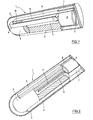
- the in the FIGS. 1 to 3 illustrated first embodiment of the sensor 1 has the shape of an elongated ampoule with the approximate dimensions of 2 mm in diameter and 8 mm in length, these data are variable within wide limits.
- the jacket 2 of the sensor 1 is formed by a semipermeable wall of cellulose, through which glucose can penetrate into the ampoule.
- the largest part of the interior of the sensor 1 is occupied by a cylindrical plastic part 3, which by several protruding on its jacket ribs 4 in Sensor 1 is centered and has an axial bore 5.
- the plastic part which is for example an injection molded part made of polycarbonate, serves on the one hand as a carrier for a vibrating member described below and on the other hand for reducing the volume of liquid in the sensor 1.
- the sensor is in the ready state with a sensitive high molecular weight liquid, for example dextran and ConA filled.
- a permanent magnet 6 is arranged in the sensor 1, which is over-injected to avoid corrosion with a plastic sheath 7 made of polycarbonate.
- the plastic casing 7, the casing 2 of the sensor 1 and the plastic part 3 are partially cut open to allow a view into the interior of the plastic part 3.
- the plastic sheath 7 serves as a support for a bending beam 8, for example, alumina ceramic, which extends along the plastic part 3.
- the plastic part 3 is flattened in the region of the bending beam 8 ( Fig. 3 ) and here carries a base substrate 9 in the form of a thin strip. Between the free end of the bending beam 8 and the base substrate 9, a spacer element 10 is provided, whose thickness is selected so that a sufficiently large vibration amplitude of the bending beam of about 100 microns is possible.
- Bending beam 8, base substrate 9 and spacer 10 are made of the same material and are produced by successive layers of laminates and subsequent packaging.
- the plastic sheath 7 carries on its the plastic part 3 facing end face a narrow., Elongated wing 11 which projects into the bore 5 of the plastic part 3.
- the permanent magnet 6 When the permanent magnet 6 is excited by an external oscillating magnetic field, it is set in vibration and with the vibration of the magnet 6 also vibrate the plastic sheath 7, the bending beam 8 and the wing 11.
- These vibrations have the fact that existing in the sensor 1 sensitive liquid is mixed with the glucose that has entered the sensor 1.
- the vibration of the blade 11 is of great importance for a rapid measurement because it simulates the flow in the sensor 1 and ensures a homogeneous glucose concentration in the sensor.
- the frequency of the magnet 6 exciting magnetic field is chosen so that it vibrates at a frequency in the range between 100 and 300 Hz. Bending beam 8 and wing 11 vibrate at the same frequency, wherein the vibration amplitude is about 100 microns or 0.1 mm. After the mixing of sensitive liquid and glucose, the magnetic field is switched off and the decay time of the vibration is measured, which is done on the basis of the magnetic field generated by the bending beam 8 with oscillating magnet 6.
- Fig. 4 shows a block diagram of the designated by the reference symbol B HMI device.
- This contains in particular a magnet 12 for generating a magnetic field 13 for the excitation of the magnet 6 in the ampoule 1 (FIG. Fig. 1 ) and a coil 14 for the excitation of the magnet 12, which also serve as a magnetic field sensor for detecting the magnetic field generated by the magnet 6 in the sensor 1, and a microprocessor 15.
- the coil 14 is on the one hand with a receiving amplifier 16 and on the other hand with a transmission amplifier 17 whose output or input is guided to the microprocessor 15.
- the microprocessor 15 is also connected to a display 18 for the currently measured glucose value and to a memory 19 for the storage of the glucose values.
- the operating unit B contains a not shown power supply.
- an additional magnetic field sensor for example a Hall sensor, can be provided for the exact positioning (normalization) of the operating device B relative to the sensor 1.
- Another possible solution for the functions excitation and detection of the HMI B is based on a rotating dipole, a hard disk motor with two permanent magnet excites the vibrations of the bending beam 8 from the outside and by analyzing the engine damping of the quality factor of the oscillator (bending beam 8 plus magnet 6 ) is determined.
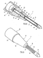
- the in the FIGS. 5 and 6 illustrated sensor 1 ' also has the shape of an elongated ampoule; he is different from the one in the FIGS. 1 to 3 represented sensor 1 essentially by the method of measuring the viscosity of the consisting of the sensitive liquid and glucose mixture. While the viscosity measurement in the sensor 1 is based on the vibration behavior of a vibrating member, it takes place in the second sensor 1 'on the basis of the rotational behavior of a measuring element. The rotational behavior of the measuring device is analyzed on the basis of its decay behavior after switching off the magnet. However, the measurement result becomes more accurate when two measuring organs are used, one of which rotates in the mixture of sensitive liquid and glucose and the other in a reference liquid.
- the reference liquid is formed by sensitive liquid.
- the sensor 1 has a rotationally symmetrical shape and consists of a cylindrical head part 20, a cylindrical measuring part 21 of smaller diameter the head part 20 has an approximate diameter of 2.5 mm and an approximate length of 3 mm, the measuring part 21 has an approximate diameter of 0.6 mm and an approximate length of 6 mm, and the reference part 22 also has an approximate length of about 6 mm.
- the head part 20 consists of an airtight housing 23, in which a drive magnet 24 is mounted.
- the drive magnet 16 is mechanically supported on two bearings 25, of which Fig. 5 only the bearing mounted in the reference part 22 front bearing is visible. The hidden by the drive magnet 24 rear of the bearing 25 is mounted on the housing 23.
- the reference part 22 comprises a frusto-conical housing 26 which has an axial bore in which an airtight, cylindrical reference chamber 27 is arranged.
- the frusto-conical housing 26 is connected to the head part 20 at its thicker end and to the measuring part 21 at its thinner end.
- a reference liquid preferably by the in the description of the FIGS. 1 to 3 said high molecular weight sensitive liquid is formed.
- a cylindrical reference member 28 is rotatably mounted in the reference chamber 27.
- the reference member 28 carries at its ends depending on a magnetic end portion 29 and 30, of which the end portion 29 forms a magnetic coupling with the drive magnet 24 and two protruding from this permanent magnet 31 and the end portion 30, a magnetic coupling with the measuring part 21. Between the two magnetic end portions 29 and 30, the reference member 28 carries a further permanent magnet 32, which is located in the level of a arranged in the housing 26 and the reference chamber 27 encompassing ring magnet 33. Ring magnet 33 and permanent magnet 32 serve to stabilize the reference member 28 in its axis of rotation. This stabilization can also be achieved by mechanical support of the axle.
- the measuring part 21 comprises a cylindrical housing 34, which is fastened at its one end in the reference part 22 and carries at its other end a termination part 22.
- the housing 34 forms a measuring chamber, in which said sensitive liquid is located, and in which a cylindrical measuring member 35 is also rotatably mounted.
- the shell of the housing 34 is provided with elongated windows 36 and lined inside with a semipermeable cellulose-formed membrane 37, through which glucose can penetrate into the measuring chamber.
- the result of the rotation of the measuring element 35 is that the sensitive liquid present in the measuring chamber is mixed with the glucose which has penetrated into it, which leads to a homogeneous glucose concentration in the measuring chamber.
- the measuring member 35 carries at its ends depending on a magnetic end portion 38 and 39, of which the reference member 28 adjacent end portion 38 for magnetic coupling with the Reference member 28 and thus used to drive the measuring element 35.
- the other end part 39 forms a magnetic coupling with a permanent magnet 40, which is fixed at the free end of the housing 34, and serves to stabilize the measuring member 35 in its axis of rotation.
- the reference numeral 41 designates a conical end part of the measuring part 21 of the sensor.
- the HMI device for in the FIGS. 5 and 6 illustrated second embodiment of the sensor is constructed substantially the same as that in Fig. 4 shown operating device B and differs from this mainly in that it contains a plurality of coils 14 for generating a rotating field, which sets the drive magnet 24 in rotation.
- the operating device has a plurality of magnetic field sensors which measure the rotation of the drive magnet 24 after switching off the magnetic rotary field.
- the drive magnet 24 drives via the magnets 31 and 29 the reference member 28 and this via the magnets 30 and 38, the measuring member 35.
- the measuring member 35 and the reference member 28 rotate in the housings 27 and 34, both the same sensitive liquid of high molecular weight contain.
- the housing 27 with the reference member 28 is sealed airtight and the housing 34 with the measuring member 35 is sealed with the semipermeable membrane 37 through which glucose can penetrate into the measuring chamber.
- the magnetic coupling between the reference member 28 (permanent magnet 30) and the measuring member 35 (permanent magnet 38) is designed so that the measuring member 35 rotates only up to a critical rotational frequency.
- the system measures the viscosity of the liquid in the housing 27 based on the decay of the rotation of the drive magnet 24 when the magnetic rotating field is switched off, and this liquid is exclusively the said sensitive liquid.
- the decay of the rotation of the drive magnet 24 when the magnetic rotating field is switched off is determined by the viscosity of the liquid mixture of sensitive liquid and glucose in the measuring chamber (housing 34). The glucose concentration determined from this information is independent of temperature, which is a significant advantage over a system without reference measurement.
- the drive magnet would directly drive the measuring element 35 via the permanent magnets 31 and 38.
- the in the FIGS. 1 to 3 shown Sensor.1 can be adapted by relatively simple modification for use as a Holtersystem in which the glucose content is continuously monitored under medical supervision and over a period of several days.
- the magnet 6 in the sensor 1 exciting magnetic field is not generated by an external magnet 12 but by a disposed inside the sensor 1 current coil, from which two thin electrical wires are passed through the skin of the patient to the outside to the control unit.
- the named current coil is preferably in the region of the spacer element 10 (FIG. Fig. 1 ) arranged.
- bending beam 8 and base substrate 9 are made of soft magnetic material.
- a current coil for the excitation of the drive magnet 24 could be arranged.
Landscapes
- Health & Medical Sciences (AREA)
- Life Sciences & Earth Sciences (AREA)
- Physics & Mathematics (AREA)
- Pathology (AREA)
- General Health & Medical Sciences (AREA)
- Engineering & Computer Science (AREA)
- Public Health (AREA)
- Animal Behavior & Ethology (AREA)
- Veterinary Medicine (AREA)
- Surgery (AREA)
- Medical Informatics (AREA)
- Molecular Biology (AREA)
- Biophysics (AREA)
- Biomedical Technology (AREA)
- Heart & Thoracic Surgery (AREA)
- General Physics & Mathematics (AREA)
- Immunology (AREA)
- Biochemistry (AREA)
- Analytical Chemistry (AREA)
- Chemical & Material Sciences (AREA)
- Computer Networks & Wireless Communication (AREA)
- Emergency Medicine (AREA)
- Optics & Photonics (AREA)
- Hematology (AREA)
- Measurement Of The Respiration, Hearing Ability, Form, And Blood Characteristics Of Living Organisms (AREA)
- Investigating Or Analysing Biological Materials (AREA)
- Investigating Or Analyzing Materials By The Use Of Magnetic Means (AREA)
- Investigating Or Analyzing Materials By The Use Of Electric Means (AREA)
Claims (20)
- Système de capteur pour la détermination du taux de glucose dans le sang, comportant un capteur (1, 1') implantable et un appareil de commande (B) associé à ce dernier, ledit capteur (1, 1') ayant la forme d'une ampoule, dans laquelle est contenu un liquide sensitif et dans laquelle le glucose peut pénétrer, ledit capteur (1, 1') mesurant la viscosité du mélange formé par le liquide sensitif et le glucose, et ledit appareil de commande (B) étant formé par un appareil portable, destiné à être porté extérieurement sur la peau, la commande de la mesure et de son évaluation étant assurée par l'appareil de commande (B), caractérisé en ce que la mesure de la viscosité est effectuée à l'appui du comportement oscillatoire d'un oscillateur (8), qui est agencé dans le capteur (1) et qui peut être stimulé en oscillation par un champ magnétique oscillant, et en ce que le comportement oscillatoire de l'oscillateur (8) est analysé à l'appui du comportement d'arrêt progressif de ce dernier après la désactivation de l'aimant (6), l'oscillateur (8) générant lui-même un champ magnétique qui est mesuré par l'appareil de commande.
- Système de capteur selon la revendication 1, caractérisé en ce que, sous l'effet de l'oscillateur, il se produit en plus une homogénéisation du liquide dans le capteur (1).
- Système de capteur selon la revendication 2, caractérisé en ce que l'oscillateur (8) est assemblé par emboîtement avec l'aimant (6) et est formé par une barre de flexion.
- Système de capteur selon la revendication 3, caractérisé en ce que l'aimant (6) est agencé sur l'une des deux extrémités de la barre de flexion et peut être amené en oscillation par un champ magnétique (13).
- Système de capteur selon la revendication 4, caractérisé en ce que ledit champ magnétique (13) est généré par un agencement électromagnétique, prévu dans l'appareil de commande (B), ou par une bobine électrique, prévue dans le capteur (1).
- Système de capteur selon l'une quelconque des revendications 1 à 5, caractérisé en ce que le capteur (1) comporte une paroi (2) hémiperméable permettant la pénétration du glucose.
- Système de capteur selon l'une quelconque des revendications 1 à 6, caractérisé par une partie en matière plastique (3), qui est agencée dans le capteur (1), remplit partiellement celui-ci et délimite donc le volume de liquide, et qui est réalisée comme support pour l'oscillateur (8) et comporte une forure (5) oblongue, dans laquelle s'engage une pale (11), agencée sur l'aimant (6) et prévue pour le brassage des liquides.
- Système de capteur selon la revendication 5, caractérisé en ce que ledit agencement électromagnétique contient des moyens d'excitation de l'aimant (6) dans le capteur (1) et un capteur de champ magnétique pour le champ magnétique généré par ledit aimant.
- Système de capteur selon la revendication 8, caractérisé en ce que lesdits moyens et ledit capteur de champ magnétique sont formés par un aimant (12) et une bobine (14) excitant celui-ci, ainsi que par un microprocesseur (15) relié à la bobine (14).
- Système de capteur pour la détermination du taux de glucose dans le sang, comportant un capteur (1, 1') implantable et un appareil de commande (B) associé à ce dernier, ledit capteur (1, 1') ayant la forme d'une ampoule, dans laquelle est contenu un liquide sensitif et dans laquelle le glucose peut pénétrer, ledit capteur (1, 1') mesurant la viscosité du mélange formé par le liquide sensitif et le glucose, et ledit appareil de commande (B) étant formé par un appareil portable, destiné à être porté extérieurement sur la peau, la commande de la mesure et de son évaluation étant assurée par l'appareil de commande (B), caractérisé en ce que la mesure de la viscosité est effectuée à l'appui de la rotation d'un élément de mesure (35), qui est agencé dans le capteur (1') et qui peut être actionné par un aimant de commande (24), également agencé dans le capteur (1'), et en ce que la rotation de l'élément de mesure (35) est analysée à l'appui du comportement d'arrêt progressif de ce dernier après la désactivation de l'aimant de commande (24).
- Système de capteur selon la revendication 10, caractérisé en ce que le capteur (1') est réalisé en deux niveaux et comporte une partie de tête (20) et une partie de mesure (21), ladite partie de tête (20) contenant l'aimant de commande (24) et ladite partie de mesure (21) contenant l'élément de mesure (35), et l'aimant de commande (24) est protégé du liquide et est agencé dans un boîtier (23).
- Système de capteur selon la revendication 11, caractérisé en ce que entre la partie de tête (20) et la partie de mesure (21) est prévue une partie de référence (22), qui relie lesdites deux parties et qui comporte une chambre (27), rendue étanche au liquide et contenant un élément de référence (28), monté rotatif, et ledit liquide sensitif.
- Système de capteur selon la revendication 11 ou 12, caractérisé en ce que la partie de tête (20) et la partie de mesure (21) ont chacune une forme cylindrique, le diamètre de la partie de tête (20) étant supérieur au diamètre de la partie de mesure (21).
- Système de capteur selon les revendications 12 et 13, caractérisé en ce que la partie de référence (22) a la forme d'un cône tronqué et en ce que l'élément de référence (28) et l'élément de mesure (35) sont réalisés sous forme de cylindres allongés.
- Système de capteur selon la revendication 14, caractérisé en ce que la partie de mesure (21) est réalisée sous la forme d'un boîtier (34) allongé, qui comporte des ouvertures (36) en forme de fenêtres et est revêtu à l'intérieur d'une feuille (37) semiperméable permettant la pénétration du glucose.
- Système de capteur selon la revendication 15, caractérisé en ce que l'aimant de commande (24) peut être entraîné en rotation par un champ magnétique, qui est généré par un agencement électromagnétique prévu dans l'appareil de commande (B).
- Système de capteur selon la revendication 16, caractérisé en ce que l'élément de mesure (35) est actionné par des couplages magnétiques (29, 31 ; 30, 38) entre l'aimant de commande (24) et l'élément de référence (28) et respectivement entre l'élément de référence (28) et l'élément de mesure (35).
- Système de capteur selon la revendication 17, caractérisé en ce que le couplage magnétique (30, 38) entre l'élément de référence (28) et l'élément de mesure (35) est configuré de telle sorte que l'élément de mesure (35) n'est entraîné en rotation que jusqu'à une fréquence de rotation critique déterminée.
- Système de capteur selon la revendication 18, caractérisé en ce que, après la désactivation du système d'entraînement de l'aimant de commande (24), l'arrêt progressif de la rotation de ce dernier au-dessus de la fréquence de rotation critique est déterminé uniquement par la viscosité du liquide sensitif dans la chambre (27) de la partie de référence (22) et, au-dessous de la fréquence de rotation critique, est déterminé par la viscosité du mélange formé par le liquide sensitif et le glucose dans le boîtier (34) de la partie de mesure (21).
- Système de capteur selon la revendication 19, caractérisé en ce qu'une valeur du taux de glucose, indépendante de la température, est déterminée à l'appui des deux valeurs de viscosité au-dessus et au-dessous de la fréquence de rotation critique.
Priority Applications (1)
| Application Number | Priority Date | Filing Date | Title |
|---|---|---|---|
| EP03750231A EP1555933B1 (fr) | 2002-10-28 | 2003-10-22 | Systeme capteur destine a la determination de la glycemie |
Applications Claiming Priority (6)
| Application Number | Priority Date | Filing Date | Title |
|---|---|---|---|
| EP02024022A EP1415590A1 (fr) | 2002-10-28 | 2002-10-28 | Capteur de glucose |
| EP02024022 | 2002-10-28 | ||
| CH00887/03A CH696259A5 (de) | 2002-10-28 | 2003-05-16 | Sensorsystem für die Bestimmumg der Glukose-Konzentration im Blut. |
| CH887032003 | 2003-05-16 | ||
| EP03750231A EP1555933B1 (fr) | 2002-10-28 | 2003-10-22 | Systeme capteur destine a la determination de la glycemie |
| PCT/CH2003/000684 WO2004037079A1 (fr) | 2002-10-28 | 2003-10-22 | Systeme capteur destine a la determination de la glycemie |
Publications (2)
| Publication Number | Publication Date |
|---|---|
| EP1555933A1 EP1555933A1 (fr) | 2005-07-27 |
| EP1555933B1 true EP1555933B1 (fr) | 2009-10-07 |
Family
ID=32178138
Family Applications (2)
| Application Number | Title | Priority Date | Filing Date |
|---|---|---|---|
| EP02024022A Withdrawn EP1415590A1 (fr) | 2002-10-28 | 2002-10-28 | Capteur de glucose |
| EP03750231A Expired - Lifetime EP1555933B1 (fr) | 2002-10-28 | 2003-10-22 | Systeme capteur destine a la determination de la glycemie |
Family Applications Before (1)
| Application Number | Title | Priority Date | Filing Date |
|---|---|---|---|
| EP02024022A Withdrawn EP1415590A1 (fr) | 2002-10-28 | 2002-10-28 | Capteur de glucose |
Country Status (16)
| Country | Link |
|---|---|
| US (1) | US7789829B2 (fr) |
| EP (2) | EP1415590A1 (fr) |
| JP (1) | JP2006503678A (fr) |
| KR (1) | KR20050055043A (fr) |
| CN (1) | CN100423684C (fr) |
| AT (1) | ATE444706T1 (fr) |
| AU (1) | AU2003269666B2 (fr) |
| BR (1) | BR0306653A (fr) |
| CA (1) | CA2503896C (fr) |
| CH (1) | CH696259A5 (fr) |
| DE (1) | DE50312007D1 (fr) |
| NO (1) | NO20052596D0 (fr) |
| PL (1) | PL374945A1 (fr) |
| TN (1) | TNSN04093A1 (fr) |
| WO (1) | WO2004037079A1 (fr) |
| YU (1) | YU47204A (fr) |
Families Citing this family (14)
| Publication number | Priority date | Publication date | Assignee | Title |
|---|---|---|---|---|
| EP1937139A2 (fr) * | 2005-10-11 | 2008-07-02 | Koninklijke Philips Electronics N.V. | Capteurs pouvant etre actives de maniere individuelle, pour capteurs implantables |
| DE102007008509B4 (de) * | 2007-02-21 | 2008-12-24 | Humboldt-Universität Zu Berlin | Verfahren zur Messung der Viskosität und viskosimetrischer Affinitätssensor |
| EP2055369A1 (fr) | 2007-10-30 | 2009-05-06 | Sensile Pat AG | Membrane revêtue perméable sensiblement |
| EP2339955B1 (fr) | 2008-07-14 | 2012-09-05 | École Polytechnique Fédérale de Lausanne (EPFL) | Biodetecteur viscosimetrique pour surveillance de taux de substance a analyser |
| EP2236077A1 (fr) | 2009-03-31 | 2010-10-06 | Sensile Pat AG | Dispositif médical pour mesurer une concentration analyte |
| CN101566549B (zh) * | 2009-05-27 | 2011-07-20 | 重庆天海医疗设备有限公司 | 血液粘度测量装置的取样/测量针 |
| ES2388846B2 (es) * | 2011-03-21 | 2013-06-04 | Universidad De Huelva | Dispositivo para la medida de propiedades reológicas y seguimiento de procesos a presión. |
| CN103519828B (zh) * | 2013-11-04 | 2015-04-29 | 理康互联科技(北京)有限公司 | 分析物检测系统及其传感标签 |
| US10004433B2 (en) * | 2014-07-07 | 2018-06-26 | Verily Life Sciences Llc | Electrochemical sensor chip |
| KR101881632B1 (ko) * | 2015-11-10 | 2018-07-24 | 이인한 | 최소 침습 연속 혈당 측정 장치 |
| US11156615B2 (en) * | 2015-11-20 | 2021-10-26 | Duke University | Glucose biosensors and uses thereof |
| CN105854685B (zh) * | 2016-06-15 | 2018-10-12 | 浙江大学 | 一种动态细胞打印微混合器 |
| EP3382370A1 (fr) * | 2017-03-30 | 2018-10-03 | University Of Oulu | Agencement de sonde et procédé de mesure rhéométrique comportant une sonde jetable et une lisibilité à distance |
| KR102279341B1 (ko) * | 2019-07-23 | 2021-07-20 | 한국과학기술원 | 진동 특성의 변화를 이용한 비침습적 생체지표 측정 방법 및 장치 |
Family Cites Families (14)
| Publication number | Priority date | Publication date | Assignee | Title |
|---|---|---|---|---|
| DD252438A1 (de) * | 1986-08-08 | 1987-12-16 | Medizin Labortechnik Veb K | Rotationsviskosimeter |
| NL9200207A (nl) * | 1992-02-05 | 1993-09-01 | Nedap Nv | Implanteerbare biomedische sensorinrichting, in het bijzonder voor meting van de glucoseconcentratie. |
| DE4334834A1 (de) * | 1993-10-13 | 1995-04-20 | Andrzej Dr Ing Grzegorzewski | Biosensor zum Messen von Viskositäts- und/oder Dichteänderungen |
| US5547049A (en) * | 1994-05-31 | 1996-08-20 | Lord Corporation | Magnetorheological fluid composite structures |
| DE19501159B4 (de) * | 1995-01-06 | 2004-05-13 | Ehwald, Rudolf, Prof. Dr.sc.nat. | Mikrosensor zur Bestimmung der Konzentration von Glukose und anderen Analyten in Flüssigkeiten auf der Basis der Affinitätsviskosimetrie |
| US5743262A (en) * | 1995-06-07 | 1998-04-28 | Masimo Corporation | Blood glucose monitoring system |
| DE19714087C2 (de) * | 1997-04-07 | 2000-06-21 | Rudolph Ehwald | Verfahren zur Affinitätsviskosimetrie und viskosimetrischer Affinitätssensor |
| GB2335496B (en) * | 1998-03-20 | 2000-06-07 | David Eglise | Sensing devices & systems |
| US6271044B1 (en) * | 1998-05-06 | 2001-08-07 | University Of Pittsburgh Of The Commonwealth System Of Higher Education | Method and kit for detecting an analyte |
| US6201980B1 (en) * | 1998-10-05 | 2001-03-13 | The Regents Of The University Of California | Implantable medical sensor system |
| US6200532B1 (en) * | 1998-11-20 | 2001-03-13 | Akzo Nobel Nv | Devices and method for performing blood coagulation assays by piezoelectric sensing |
| US7284413B2 (en) * | 2000-05-26 | 2007-10-23 | Rudolf Ehwald | Method and apparatus for measuring viscosity |
| US6668621B1 (en) * | 2002-06-13 | 2003-12-30 | Hubert Arthur Wright | Viscosity measurement by means of damped resonant vibration normal to an approximate rigid plate |
| US7226414B2 (en) * | 2002-10-09 | 2007-06-05 | Biotex, Inc. | Method and apparatus for analyte sensing |
-
2002
- 2002-10-28 EP EP02024022A patent/EP1415590A1/fr not_active Withdrawn
-
2003
- 2003-05-16 CH CH00887/03A patent/CH696259A5/de not_active IP Right Cessation
- 2003-10-22 PL PL03374945A patent/PL374945A1/xx not_active Application Discontinuation
- 2003-10-22 KR KR1020057007306A patent/KR20050055043A/ko not_active Application Discontinuation
- 2003-10-22 JP JP2005501492A patent/JP2006503678A/ja active Pending
- 2003-10-22 AU AU2003269666A patent/AU2003269666B2/en not_active Ceased
- 2003-10-22 CN CNB2003801022578A patent/CN100423684C/zh not_active Expired - Fee Related
- 2003-10-22 BR BR0306653-3A patent/BR0306653A/pt not_active IP Right Cessation
- 2003-10-22 US US10/532,897 patent/US7789829B2/en not_active Expired - Fee Related
- 2003-10-22 CA CA2503896A patent/CA2503896C/fr not_active Expired - Fee Related
- 2003-10-22 WO PCT/CH2003/000684 patent/WO2004037079A1/fr active Application Filing
- 2003-10-22 YU YU47204A patent/YU47204A/sh unknown
- 2003-10-22 DE DE50312007T patent/DE50312007D1/de not_active Expired - Lifetime
- 2003-10-22 EP EP03750231A patent/EP1555933B1/fr not_active Expired - Lifetime
- 2003-10-22 AT AT03750231T patent/ATE444706T1/de not_active IP Right Cessation
-
2004
- 2004-05-27 TN TNP2004000093A patent/TNSN04093A1/en unknown
-
2005
- 2005-05-30 NO NO20052596A patent/NO20052596D0/no not_active Application Discontinuation
Also Published As
| Publication number | Publication date |
|---|---|
| NO20052596L (no) | 2005-05-30 |
| US7789829B2 (en) | 2010-09-07 |
| EP1415590A1 (fr) | 2004-05-06 |
| WO2004037079A1 (fr) | 2004-05-06 |
| EP1555933A1 (fr) | 2005-07-27 |
| YU47204A (sh) | 2006-05-25 |
| JP2006503678A (ja) | 2006-02-02 |
| CA2503896A1 (fr) | 2004-05-06 |
| NO20052596D0 (no) | 2005-05-30 |
| CN1708254A (zh) | 2005-12-14 |
| KR20050055043A (ko) | 2005-06-10 |
| CN100423684C (zh) | 2008-10-08 |
| DE50312007D1 (de) | 2009-11-19 |
| CH696259A5 (de) | 2007-03-15 |
| TNSN04093A1 (en) | 2006-06-01 |
| CA2503896C (fr) | 2012-11-27 |
| AU2003269666A1 (en) | 2004-05-13 |
| PL374945A1 (en) | 2005-11-14 |
| AU2003269666B2 (en) | 2008-09-11 |
| BR0306653A (pt) | 2004-10-05 |
| ATE444706T1 (de) | 2009-10-15 |
| US20060100493A1 (en) | 2006-05-11 |
Similar Documents
| Publication | Publication Date | Title |
|---|---|---|
| EP1555933B1 (fr) | Systeme capteur destine a la determination de la glycemie | |
| DE60318323T2 (de) | Kalibrationstechnik für nichtinvasive medizinische vorrichtungen | |
| DE69728525T2 (de) | Mittels vakuum verbesserter transdermaler flüssigkeitstransport | |
| DE60310159T3 (de) | Vorrichtung und Verfahren zur Zufuhr und Analyse von einer physiologischen Flüssigkeit | |
| DE69829399T2 (de) | Katheter mit neben dem distalen ende angeordnetem druckgeber | |
| EP1404217B1 (fr) | Mesurage de la concentration de substances dans des organismes vivants par microdialyse | |
| DE10392210T5 (de) | Verfahren und Vorrichtung zum Überwachen einer analytischen Konzentration mittels einer Osmose-Differenz-Druckmessung | |
| DE10156384A1 (de) | System zur Überwachung und Steuerung von Druck- und Konzentrationswerten in einem Fluidkanal | |
| DE3623711A1 (de) | Vorrichtung zum feststellen von eigenschaften, verschiedenheiten und veraenderungen des menschlichen oder tierischen koerpers | |
| DE102008045878A1 (de) | Schlauch- oder röhrenförmige medizinische Einrichtung mit einem Führungslumen | |
| DE10305831A1 (de) | Diagnosegerät | |
| Hupé et al. | Spatial and temporal parameters of cortical inactivation by GABA | |
| Waltz | Sweet sensation | |
| DE10020352A1 (de) | Implantierbares Blutzuckermessgerät | |
| DE4405149C2 (de) | Anordnung zum Bestimmen der Konzentration von Inhaltsstoffen in Körperflüssigkeiten | |
| DE212008000064U1 (de) | Vorrichtung zur Überwachung der Diabetes-Insulin-Therapie | |
| EP1793321B1 (fr) | Procédé d évaluation et système d analyse d'un analyte dans le fluide corporel humain ou animal | |
| DE102011078711A1 (de) | Vaskulare Zugangsvorrichtung mit auslesbarer Speichereinheit | |
| DE19507107C1 (de) | Implantierbares Sensorsystem zur Bestimmung von Stoffkonzentrationen in lebenden Organismen | |
| DE102006045952A1 (de) | Biosensor mit einem RFID-System für eine Parameterkonfiguration | |
| WO2003030706A2 (fr) | Dispositif a introduire dans des organes corporels creux | |
| EP2440114B1 (fr) | Dispositif pour la mesure transcutanée in vivo de la concentration d'au moins un analyte dans un organisme vivant | |
| DE3525588C2 (fr) | ||
| DE1616006C (de) | Schaltung zum Überwachen der Durchlas sigkeit des Zellgewebes eines lebenden Korpers fur eine körpereigene Flüssigkeit, insbesondere eine Glykoselosung | |
| EP1364613A1 (fr) | Dispositif d'examen et de surveillance de la santé |
Legal Events
| Date | Code | Title | Description |
|---|---|---|---|
| PUAI | Public reference made under article 153(3) epc to a published international application that has entered the european phase |
Free format text: ORIGINAL CODE: 0009012 |
|
| 17P | Request for examination filed |
Effective date: 20050427 |
|
| AK | Designated contracting states |
Kind code of ref document: A1 Designated state(s): AT BE BG CH CY CZ DE DK EE ES FI FR GB GR HU IE IT LI LU MC NL PT RO SE SI SK TR |
|
| AX | Request for extension of the european patent |
Extension state: AL LT LV MK |
|
| DAX | Request for extension of the european patent (deleted) | ||
| 17Q | First examination report despatched |
Effective date: 20070702 |
|
| RAP1 | Party data changed (applicant data changed or rights of an application transferred) |
Owner name: SENSILE PAT AG |
|
| GRAP | Despatch of communication of intention to grant a patent |
Free format text: ORIGINAL CODE: EPIDOSNIGR1 |
|
| GRAS | Grant fee paid |
Free format text: ORIGINAL CODE: EPIDOSNIGR3 |
|
| GRAA | (expected) grant |
Free format text: ORIGINAL CODE: 0009210 |
|
| AK | Designated contracting states |
Kind code of ref document: B1 Designated state(s): AT BE BG CH CY CZ DE DK EE ES FI FR GB GR HU IE IT LI LU MC NL PT RO SE SI SK TR |
|
| REG | Reference to a national code |
Ref country code: GB Ref legal event code: FG4D Free format text: NOT ENGLISH |
|
| REG | Reference to a national code |
Ref country code: CH Ref legal event code: EP |
|
| REG | Reference to a national code |
Ref country code: IE Ref legal event code: FG4D |
|
| REF | Corresponds to: |
Ref document number: 50312007 Country of ref document: DE Date of ref document: 20091119 Kind code of ref document: P |
|
| PG25 | Lapsed in a contracting state [announced via postgrant information from national office to epo] |
Ref country code: SI Free format text: LAPSE BECAUSE OF FAILURE TO SUBMIT A TRANSLATION OF THE DESCRIPTION OR TO PAY THE FEE WITHIN THE PRESCRIBED TIME-LIMIT Effective date: 20091007 |
|
| NLV1 | Nl: lapsed or annulled due to failure to fulfill the requirements of art. 29p and 29m of the patents act | ||
| REG | Reference to a national code |
Ref country code: CH Ref legal event code: PUE Owner name: COLE POLYTECHNIQUE FEDERALE DE LAUSANNE (EPFL) Free format text: SENSILE PAT AG#ZUGERSTRASSE 76B#6340 BAAR (CH) -TRANSFER TO- ECOLE POLYTECHNIQUE FEDERALE DE LAUSANNE (EPFL)#SRI, STATION 10#1015 LAUSANNE (CH) Ref country code: CH Ref legal event code: NV Representative=s name: REUTELER & CIE S.A. |
|
| RAP2 | Party data changed (patent owner data changed or rights of a patent transferred) |
Owner name: ECOLE POLYTECHNIQUE FEDERALE DE LAUSANNE (EPFL) |
|
| BERE | Be: lapsed |
Owner name: SENSILE PAT A.G. Effective date: 20091031 |
|
| PG25 | Lapsed in a contracting state [announced via postgrant information from national office to epo] |
Ref country code: FI Free format text: LAPSE BECAUSE OF FAILURE TO SUBMIT A TRANSLATION OF THE DESCRIPTION OR TO PAY THE FEE WITHIN THE PRESCRIBED TIME-LIMIT Effective date: 20091007 Ref country code: SE Free format text: LAPSE BECAUSE OF FAILURE TO SUBMIT A TRANSLATION OF THE DESCRIPTION OR TO PAY THE FEE WITHIN THE PRESCRIBED TIME-LIMIT Effective date: 20091007 Ref country code: PT Free format text: LAPSE BECAUSE OF FAILURE TO SUBMIT A TRANSLATION OF THE DESCRIPTION OR TO PAY THE FEE WITHIN THE PRESCRIBED TIME-LIMIT Effective date: 20100208 Ref country code: ES Free format text: LAPSE BECAUSE OF FAILURE TO SUBMIT A TRANSLATION OF THE DESCRIPTION OR TO PAY THE FEE WITHIN THE PRESCRIBED TIME-LIMIT Effective date: 20100118 |
|
| REG | Reference to a national code |
Ref country code: IE Ref legal event code: FD4D |
|
| PG25 | Lapsed in a contracting state [announced via postgrant information from national office to epo] |
Ref country code: MC Free format text: LAPSE BECAUSE OF NON-PAYMENT OF DUE FEES Effective date: 20091031 |
|
| PG25 | Lapsed in a contracting state [announced via postgrant information from national office to epo] |
Ref country code: RO Free format text: LAPSE BECAUSE OF FAILURE TO SUBMIT A TRANSLATION OF THE DESCRIPTION OR TO PAY THE FEE WITHIN THE PRESCRIBED TIME-LIMIT Effective date: 20091007 Ref country code: IE Free format text: LAPSE BECAUSE OF FAILURE TO SUBMIT A TRANSLATION OF THE DESCRIPTION OR TO PAY THE FEE WITHIN THE PRESCRIBED TIME-LIMIT Effective date: 20091007 Ref country code: BG Free format text: LAPSE BECAUSE OF FAILURE TO SUBMIT A TRANSLATION OF THE DESCRIPTION OR TO PAY THE FEE WITHIN THE PRESCRIBED TIME-LIMIT Effective date: 20100107 Ref country code: NL Free format text: LAPSE BECAUSE OF FAILURE TO SUBMIT A TRANSLATION OF THE DESCRIPTION OR TO PAY THE FEE WITHIN THE PRESCRIBED TIME-LIMIT Effective date: 20091007 Ref country code: DK Free format text: LAPSE BECAUSE OF FAILURE TO SUBMIT A TRANSLATION OF THE DESCRIPTION OR TO PAY THE FEE WITHIN THE PRESCRIBED TIME-LIMIT Effective date: 20091007 Ref country code: EE Free format text: LAPSE BECAUSE OF FAILURE TO SUBMIT A TRANSLATION OF THE DESCRIPTION OR TO PAY THE FEE WITHIN THE PRESCRIBED TIME-LIMIT Effective date: 20091007 |
|
| PLBE | No opposition filed within time limit |
Free format text: ORIGINAL CODE: 0009261 |
|
| STAA | Information on the status of an ep patent application or granted ep patent |
Free format text: STATUS: NO OPPOSITION FILED WITHIN TIME LIMIT |
|
| PG25 | Lapsed in a contracting state [announced via postgrant information from national office to epo] |
Ref country code: SK Free format text: LAPSE BECAUSE OF FAILURE TO SUBMIT A TRANSLATION OF THE DESCRIPTION OR TO PAY THE FEE WITHIN THE PRESCRIBED TIME-LIMIT Effective date: 20091007 Ref country code: CZ Free format text: LAPSE BECAUSE OF FAILURE TO SUBMIT A TRANSLATION OF THE DESCRIPTION OR TO PAY THE FEE WITHIN THE PRESCRIBED TIME-LIMIT Effective date: 20091007 |
|
| 26N | No opposition filed |
Effective date: 20100708 |
|
| PG25 | Lapsed in a contracting state [announced via postgrant information from national office to epo] |
Ref country code: BE Free format text: LAPSE BECAUSE OF NON-PAYMENT OF DUE FEES Effective date: 20091031 Ref country code: GR Free format text: LAPSE BECAUSE OF FAILURE TO SUBMIT A TRANSLATION OF THE DESCRIPTION OR TO PAY THE FEE WITHIN THE PRESCRIBED TIME-LIMIT Effective date: 20100108 |
|
| PG25 | Lapsed in a contracting state [announced via postgrant information from national office to epo] |
Ref country code: AT Free format text: LAPSE BECAUSE OF NON-PAYMENT OF DUE FEES Effective date: 20091022 |
|
| PG25 | Lapsed in a contracting state [announced via postgrant information from national office to epo] |
Ref country code: IT Free format text: LAPSE BECAUSE OF FAILURE TO SUBMIT A TRANSLATION OF THE DESCRIPTION OR TO PAY THE FEE WITHIN THE PRESCRIBED TIME-LIMIT Effective date: 20091007 |
|
| PG25 | Lapsed in a contracting state [announced via postgrant information from national office to epo] |
Ref country code: LU Free format text: LAPSE BECAUSE OF NON-PAYMENT OF DUE FEES Effective date: 20091022 |
|
| PG25 | Lapsed in a contracting state [announced via postgrant information from national office to epo] |
Ref country code: HU Free format text: LAPSE BECAUSE OF FAILURE TO SUBMIT A TRANSLATION OF THE DESCRIPTION OR TO PAY THE FEE WITHIN THE PRESCRIBED TIME-LIMIT Effective date: 20100408 |
|
| PG25 | Lapsed in a contracting state [announced via postgrant information from national office to epo] |
Ref country code: TR Free format text: LAPSE BECAUSE OF FAILURE TO SUBMIT A TRANSLATION OF THE DESCRIPTION OR TO PAY THE FEE WITHIN THE PRESCRIBED TIME-LIMIT Effective date: 20091007 |
|
| PG25 | Lapsed in a contracting state [announced via postgrant information from national office to epo] |
Ref country code: CY Free format text: LAPSE BECAUSE OF FAILURE TO SUBMIT A TRANSLATION OF THE DESCRIPTION OR TO PAY THE FEE WITHIN THE PRESCRIBED TIME-LIMIT Effective date: 20091007 |
|
| PGFP | Annual fee paid to national office [announced via postgrant information from national office to epo] |
Ref country code: DE Payment date: 20141022 Year of fee payment: 12 Ref country code: FR Payment date: 20141022 Year of fee payment: 12 Ref country code: CH Payment date: 20141021 Year of fee payment: 12 Ref country code: GB Payment date: 20141021 Year of fee payment: 12 |
|
| REG | Reference to a national code |
Ref country code: DE Ref legal event code: R119 Ref document number: 50312007 Country of ref document: DE |
|
| REG | Reference to a national code |
Ref country code: CH Ref legal event code: PL |
|
| GBPC | Gb: european patent ceased through non-payment of renewal fee |
Effective date: 20151022 |
|
| PG25 | Lapsed in a contracting state [announced via postgrant information from national office to epo] |
Ref country code: LI Free format text: LAPSE BECAUSE OF NON-PAYMENT OF DUE FEES Effective date: 20151031 Ref country code: CH Free format text: LAPSE BECAUSE OF NON-PAYMENT OF DUE FEES Effective date: 20151031 Ref country code: DE Free format text: LAPSE BECAUSE OF NON-PAYMENT OF DUE FEES Effective date: 20160503 Ref country code: GB Free format text: LAPSE BECAUSE OF NON-PAYMENT OF DUE FEES Effective date: 20151022 |
|
| REG | Reference to a national code |
Ref country code: FR Ref legal event code: ST Effective date: 20160630 |
|
| PG25 | Lapsed in a contracting state [announced via postgrant information from national office to epo] |
Ref country code: FR Free format text: LAPSE BECAUSE OF NON-PAYMENT OF DUE FEES Effective date: 20151102 |