EP1555717A1 - Mobiles Kommunikationsendgerät mit Schleifenantenne - Google Patents
Mobiles Kommunikationsendgerät mit Schleifenantenne Download PDFInfo
- Publication number
- EP1555717A1 EP1555717A1 EP04022800A EP04022800A EP1555717A1 EP 1555717 A1 EP1555717 A1 EP 1555717A1 EP 04022800 A EP04022800 A EP 04022800A EP 04022800 A EP04022800 A EP 04022800A EP 1555717 A1 EP1555717 A1 EP 1555717A1
- Authority
- EP
- European Patent Office
- Prior art keywords
- line
- loop antenna
- power supply
- mobile communication
- communication terminal
- Prior art date
- Legal status (The legal status is an assumption and is not a legal conclusion. Google has not performed a legal analysis and makes no representation as to the accuracy of the status listed.)
- Granted
Links
Images


Classifications
-
- H—ELECTRICITY
- H01—ELECTRIC ELEMENTS
- H01Q—ANTENNAS, i.e. RADIO AERIALS
- H01Q1/00—Details of, or arrangements associated with, antennas
- H01Q1/12—Supports; Mounting means
- H01Q1/22—Supports; Mounting means by structural association with other equipment or articles
- H01Q1/24—Supports; Mounting means by structural association with other equipment or articles with receiving set
- H01Q1/241—Supports; Mounting means by structural association with other equipment or articles with receiving set used in mobile communications, e.g. GSM
- H01Q1/242—Supports; Mounting means by structural association with other equipment or articles with receiving set used in mobile communications, e.g. GSM specially adapted for hand-held use
- H01Q1/243—Supports; Mounting means by structural association with other equipment or articles with receiving set used in mobile communications, e.g. GSM specially adapted for hand-held use with built-in antennas
-
- H—ELECTRICITY
- H01—ELECTRIC ELEMENTS
- H01Q—ANTENNAS, i.e. RADIO AERIALS
- H01Q1/00—Details of, or arrangements associated with, antennas
- H01Q1/12—Supports; Mounting means
- H01Q1/22—Supports; Mounting means by structural association with other equipment or articles
- H01Q1/24—Supports; Mounting means by structural association with other equipment or articles with receiving set
- H01Q1/241—Supports; Mounting means by structural association with other equipment or articles with receiving set used in mobile communications, e.g. GSM
- H01Q1/242—Supports; Mounting means by structural association with other equipment or articles with receiving set used in mobile communications, e.g. GSM specially adapted for hand-held use
- H01Q1/245—Supports; Mounting means by structural association with other equipment or articles with receiving set used in mobile communications, e.g. GSM specially adapted for hand-held use with means for shaping the antenna pattern, e.g. in order to protect user against rf exposure
-
- H—ELECTRICITY
- H01—ELECTRIC ELEMENTS
- H01Q—ANTENNAS, i.e. RADIO AERIALS
- H01Q5/00—Arrangements for simultaneous operation of antennas on two or more different wavebands, e.g. dual-band or multi-band arrangements
- H01Q5/30—Arrangements for providing operation on different wavebands
- H01Q5/307—Individual or coupled radiating elements, each element being fed in an unspecified way
- H01Q5/342—Individual or coupled radiating elements, each element being fed in an unspecified way for different propagation modes
- H01Q5/357—Individual or coupled radiating elements, each element being fed in an unspecified way for different propagation modes using a single feed point
- H01Q5/364—Creating multiple current paths
- H01Q5/371—Branching current paths
-
- H—ELECTRICITY
- H01—ELECTRIC ELEMENTS
- H01Q—ANTENNAS, i.e. RADIO AERIALS
- H01Q5/00—Arrangements for simultaneous operation of antennas on two or more different wavebands, e.g. dual-band or multi-band arrangements
- H01Q5/30—Arrangements for providing operation on different wavebands
- H01Q5/378—Combination of fed elements with parasitic elements
-
- H—ELECTRICITY
- H01—ELECTRIC ELEMENTS
- H01Q—ANTENNAS, i.e. RADIO AERIALS
- H01Q7/00—Loop antennas with a substantially uniform current distribution around the loop and having a directional radiation pattern in a plane perpendicular to the plane of the loop
Definitions
- the present invention relates to a mobile communication terminal, particularly, to a mobile communication terminal equipped with a loop antenna housed in the casing of the mobile communication terminal.
- a loop antenna in which the directivity characteristics of radiated electric wave is controlled is disclosed in, for example, Japanese Patent Disclosure (Kokai) No. 2001-237637.
- a waveguide plate having a surface parallel to the plane of the loop antenna is arranged at a position a prescribed distance apart from the plane of the loop antenna in the vertical direction.
- the loop antenna exhibits the radiation characteristics of the electric wave having a directivity in a direction perpendicular to the plane of the loop antenna.
- the loop antenna exhibits the greatest radiation characteristics toward the waveguide plate.
- the loop antenna is combined with the waveguide plate so as to utilize the loop antenna as a primary radiator of a parabolic antenna.
- the line length of the loop antenna that is determined by the wavelength is rendered considerably large. Since the loop antenna is housed in the portable telephone, the line length of the loop antenna is secured by arranging the front surface of the portable telephone on which is positioned the receiver in parallel to the plane of the loop antenna.
- An object of the present invention is to provide a loop antenna exhibiting a radiation directivity that the radiation toward the user of the portable telephone is avoided.
- a mobile communication terminal comprising:
- FIG. 1 schematically shows the configuration of a portable telephone, in which the loop antenna according to each of the embodiments of the present invention can be housed, together with the coordinate system.
- the coordinate system shown in FIG. 1 indicates the front direction, the rear direction, the left direction, the right direction, the upper direction and the down direction in the portable telephone shown in FIG. 1.
- the front direction is defined to be the positive direction in the X-axis
- the right direction is defined to be the positive direction in the Y-axis
- the upper direction is defined to be the positive direction in the Z-axis.
- a receiver 201 including a loud speaker is arranged in the upper portion and a transmitter 202 including a microphone is arranged in the lower portion on the front surface 200 of the portable telephone 50.
- the ear of the user of the portable telephone 50 is allowed to abut against the receiver 201, and the mouth of the user is positioned close to the transmitter 202. It follows that the front direction corresponds to the direction in which the portable telephone 50 is allowed to face the user of the portable telephone 50.
- a loop antenna 100 having a loop shape on a plane substantially parallel to the front surface 200 (YZ plane) is arranged inside the portable telephone 40.
- the loop antenna 100 includes a looped line 1 and a power supply point 2 positioned in the lower portion of the looped line 1 for supplying an electric current to the looped line 1.
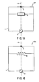
- FIGS. 2 to 5 collectively show a first embodiment in which the technical idea of the present invention is applied to a portable telephone.
- FIG. 2 schematically shows the configuration of a loop antenna 101.
- FIG. 3 shows the current distribution for explaining the operating principle of the loop antenna.
- FIG. 4 shows the radiation pattern of the electromagnetic field within the loop antenna.
- FIG. 5 is a graph showing the relationship between the value of VSWR (Voltage Standing Wave Ratio) and the frequency based on the power supply point.
- VSWR Voltage Standing Wave Ratio
- the loop antenna 101 shown in FIG. 2 comprises a line 1 forming a rectangular loop and a power supply point 2 for supplying a current to the line 1.
- the right portion and the left portion of the looped line 1 are arranged in symmetry with respect to a symmetric line 4 extending through a half point 3 in respect of the line length of the line 1 and the power supply point 2.
- the line corresponding to the right side or the left side of the loop is defined to have a length equal to a 1/2 wavelength ( ⁇ /2) of an electric wave having a prescribed frequency.
- the entire length of the line 1 including the four sides of the rectangular loop is defined to be equal to two wavelengths (2 ⁇ ) of the prescribed frequency.
- the half point 3 corresponds to the position apart from the power supply point 2 along the looped line 1 by one wavelength.
- FIG. 2 also shows the coordinate system denoting the front direction, the rear direction, the left direction, the right direction, the upper direction and the down direction as in FIG. 1 for clearly setting forth the arranging direction of the loop antenna.
- FIG. 3 shows the distribution of the current flowing within the loop antenna 101 shown in FIG. 2.
- a driving current flows into the line 1.
- the driving current is rendered maximum at the power supply point 2 and at points P1 and P2, which are apart from the power supply point 2 by 1/2 wavelength along the line 1.
- the driving current is also rendered maximum at point P3, which is apart from the point P1 or P2 by 1/2 wavelength along the line 1.
- a driving current vector is generated in each side of the rectangular line 1. To be more specific, driving current vectors 1a, 1b in the negative Z direction are generated on the right side portion of the rectangular line 1, and driving current vectors 1c, 1d in the positive Z direction are generated on the left side portion of the rectangular line 1.
- driving current vectors 1e, 1f in the negative Y direction are generated in the upper side portion of the rectangular line 1
- driving current vectors 1g, 1h in the positive Y direction are generated in the lower side portion of the rectangular line 1. It follows that an electromagnetic field is generated around the loop antenna 101, and the electromagnetic field thus generated is radiated to the free space. It should be noted that the driving current vectors have opposite phases with respect to the symmetric line 4.
- FIG. 4 shows the result of the simulation of the radiation pattern of the electromagnetic field generated within the XY plane by the driving current vectors shown in FIG. 3.
- the driving current vectors are generated in opposite phases that are in symmetry with respect to the symmetric line 4 as shown in FIG. 3. It follows that an electromagnetic field is radiated around the loop antenna 101, and the radiated electromagnetic field is combined and generated in the surrounding free space as a combined radiation pattern.
- the central portion in the right-left direction of the radiation pattern is constricted in the front-rear direction so as to form a null.
- the front direction is the direction toward the user of the portable telephone.
- the null is generated in the front direction so as to lower the intensity of the electric field.
- FIG. 5 shows the frequency characteristics of VSWR at the power supply point 2 shown in FIG. 2.
- the loop antenna 101 shown in FIG. 2 exhibits the frequency characteristics of a single ridge type, which has a single resonance point that is determined by the length of the line 1, as shown in FIG. 5.
- a null is generated in the radiation characteristics in a direction perpendicular to the plane of the loop antenna, i.e., in the direction toward the user of the portable telephone. Since the null is generated in the direction toward the human body, which can be regarded as a dielectric element, it is substantially possible to prevent the mismatch loss and the dielectric loss derived from the human body so as to improve the antenna radiation efficiency.
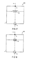
- FIGS. 6 to 9 collectively show a second embodiment in which the technical idea of the present invention is applied to a loop antenna for a portable telephone.
- FIG. 6 schematically shows the configuration of the loop antenna.
- FIG. 7 shows a loop antenna equipped with a specific component as a miniaturizing unit shown in FIG. 6.
- FIG. 8 shows a loop antenna equipped with another specific component as a miniaturizing unit.
- FIG. 9 shows a loop antenna equipped with still another specific component as a miniaturizing unit.
- a component 5 for miniaturizing a loop antenna 102 is connected to the right side portion of the line 1 of the loop antenna 102.
- a component 6 for miniaturizing the loop antenna 102 is connected to the left side portion of the line 1 of the loop antenna 102.
- These miniaturizing components 5 and 6 are arranged in symmetry with respect to the symmetric line 4. It should be noted that each of the miniaturizing components 5 and 6 corresponds to the section in which the line is shaped like a meander, i.e., shaped zigzag, or is formed helical, or corresponds to, for example, a dielectric element mounted to the line, and has an electric line length larger than the mechanical size.
- the electric line length is imparted to the loop antenna 102 so as to set the loop antenna 102 at a prescribed line length.
- a prescribed entire length of the electrical line of the line 1 corresponding to the length along the four sides of the rectangular line 1 is set at the length equal to two wavelengths of a prescribed frequency, and the half point 3 is set at the position apart from the power supply point 2 by one wavelength along the line 1.
- the loop antenna 102 shown in FIG. 6 exhibits the characteristics similar to those of the loop antenna shown in FIG. 2. It is also possible to form the loop antenna 102 with a small equivalent electric line length. As a result, the portable telephone equipped with the loop antenna 102 as shown in FIG. 6 can be made smaller in size.
- the loop antenna 102a it is possible for the loop antenna 102a to comprise meander-like miniaturizing means 5a and 6a as the miniaturizing components 5 and 6. Also, as shown in FIG. 8, it is possible for the loop antenna 102b to comprise helical miniaturizing means 5b, 6b as the miniaturizing components 5 and 6. Further, as shown in FIG. 9, it is possible for the loop antenna 102c to comprise dielectric elements 5c and 6c as the miniaturizing components 5 and 6.
- FIGS. 10 and 11 collectively show a loop antenna for a portable telephone according to a third embodiment of the present invention.
- FIG. 10 is an oblique view schematically showing the configuration of the loop antenna 103
- FIG. 11 schematically shows another construction relating to a modification of the loop antenna shown in FIG. 10.
- the upper and lower portions of the looped line 1 are folded toward the inside of the loop antenna 103, and the right side section and the left side section are erected relative to the plane including the upper portion and the lower portion of the line 1.
- the entire length of the line 1 starting from the power supply point 2, passing through the half point 3, and ending in the power supply point 2 is set at the length equal to two wavelengths of a prescribed frequency, and the half point 3 is positioned one wavelength apart from the power supply point 2.
- FIG. 11 shows a loop antenna, which has another construction relating to a modification of the loop antenna shown in FIG. 10.
- the upper side section of the line 1 is not linear but is folded in a manner to form right and left sections that are shaped in symmetry with respect to the symmetric line 4.
- the upper portion of the loop antenna 104 is substantially shaped like a letter T as a whole.
- the lower side section of the line 1 is not linear but is folded in a manner to form right and left sections that are shaped in symmetry with respect to the symmetric line 4.
- the lower portion of the loop antenna 104 is substantially shaped like a letter T that is reversed as a whole.
- the entire length of the line 1 starting from the power supply point 2, passing through the half point 3, and ending in the power supply point 2 is set at the length equal to two wavelengths of a prescribed frequency, and the half point 3 is positioned one wavelength apart from the power supply point 2.
- the folding shape is not limited to the shape of a letter T (entire shape) as far as the right and left portions of the folded structure are in symmetry with respect to the symmetric line 4. In other words, it is possible for each of the upper side section and the lower side section of the line 1 to be folded in another shape.
- each of FIGS. 10 and 11 it is possible to diminish the size of the entire loop antenna by folding a part of the line 1 while securing the line length of the line 1.
- the loop antenna shown in each of FIGS. 10 and 11 has a line length equal to that of the loop antenna shown in FIG. 2 and is shaped such that right and left sections of the loop antenna are in symmetry with respect to the symmetric line 4. It follows that the characteristics of each of the loop antennas 103 and 104 shown in FIGS. 10 and 11 are equal to those of the loop antenna shown in FIG. 2. Also, since the small loop antenna 104 can be formed with the line length equal to that of the loop antenna shown in FIG. 2, the portable telephone housing the loop antenna can be made smaller in size.
- FIG. 12 shows the configuration of a loop antenna, which can be used in the portable telephone shown in FIG. 1, according to a fourth embodiment of the present invention.
- the line 1 is short-circuited at one end to a ground plate 7 an is connected at the other end to the power supply point 2.
- the short-circuiting point to the ground plate 7 and the power supply point 2 are arranged in the vicinity of the symmetric line 4.
- the line length of the line 1 is set equal to two wavelengths, and the right and left sections of the loop antenna 105 are formed in symmetry with respect to the symmetric line 4.
- the loop antenna 105 Since one end of the line 1 is connected to the ground plate 7, the loop antenna 105 is of an imbalance type.
- the transmitting-receiving circuit (not shown) on the side of the portable telephone body, which is connected to the power supply point 2, is equipped with an imbalance type power supply circuit.
- the imbalance type loop antenna and the imbalance type transmitting-receiving circuit can be directly connected to each other without employing the imbalance-balance conversion, i.e., can be connected with the imbalance state left unchanged.
- the loss in the imbalance-balance converting circuit (not shown) can be eliminated so as to improve the radiation efficiency.
- FIGS. 13 and 14 collectively show a fifth embodiment, in which the technical idea of the present invention is applied to a loop antenna for a portable telephone.
- FIG. 13 shows the configuration of a loop antenna 106
- FIG. 14 is a graph showing the relationship between VSWR at the power supply point and the frequency.
- the loop antenna 106 shown in FIG. 13 comprises a short-circuiting line 8 formed midway of the loop of the line 1 so as to achieve the short-circuiting between the right side portion and the left side portion of the line 1.
- Two loops including an outside loop having a larger line length and passing through the power supply point 2 and an inside loop having a smaller line length and passing through the power supply point 2 are formed because of the presence of the short-circuiting line, with the result that two different resonance frequencies are imparted to the loop antenna 106.
- FIG. 14 is a graph showing the relationship between the VSWR value at the power supply point and the frequency in the loop antenna 106 shown in FIG. 13. It can be understood from FIG. 14 that generated are two resonance frequencies including a resonant point of the resonance frequency corresponding to the outside loop having a large line length and another resonant point of the resonance frequency corresponding to the inside loop having a small line length.
- the loop antenna shown in FIG. 13 has two different resonance frequencies, the loop antenna can be incorporated in a portable telephone that can be utilized under the dual mode of two different frequencies.
- FIGS. 15 to 18 collectively shows a six embodiment, in which the technical idea of the present invention is applied to a loop antenna for a portable telephone.
- FIG. 15 shows the configuration of a loop antenna 107.
- FIG. 16 shows a specific configuration of the loop antenna shown in FIG. 15.
- FIG. 17 shows another specific configuration of the loop antenna shown in FIG. 15.
- FIG. 18 shows still another specific configuration of the loop antenna shown in FIG. 15.
- a component 9 for miniaturizing the loop antenna is arranged on the symmetric line 4 so as to be connected to a short-circuiting line configured to form the short-circuiting between the right side section and the left side section of the line 1.
- the miniaturizing component 9 corresponds to a meander component in which the line is formed zigzag, to a line component in which the line is formed helical, or to a dielectric element.
- the miniaturizing component 9 permits an electric line length not smaller than the mechanical size to be imparted to the second loop of the loop antenna. It follows that the two different resonance frequencies shown in FIG. 14 can be adjusted to a prescribed value by the miniaturizing component 9.
- FIG. 16 shows a loop antenna 107a comprising a meander component 9a as the miniaturizing component 9 shown in FIG. 15.
- FIG. 17 shows a loop antenna 107b comprising a helical component 9b as the miniaturizing component 9 shown in FIG. 15.
- FIG. 18 shows a loop antenna 107c comprising a dielectric component 9c as the miniaturizing component 9 shown in FIG. 15.
- the loop antenna shown in each of FIGS. 15 to 18 has two different resonance frequencies, it is possible to incorporate the loop antenna in a portable telephone of a dual mode of two frequencies. It is also possible for the short-circuiting portion to decrease the length of the miniaturizing component.
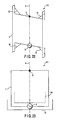
- FIG. 19 shows the configuration of a loop antenna according to a seventh embodiment in which the technical idea of the present invention is applied to a loop antenna for a portable telephone.
- the upper portion and the lower portion of the line 1 are folded toward the inner region of the loop antenna 108, and the right side section and the left side section of the loop antenna 108 are erected on the plane including the upper portion and the lower portion of the line 1 as in the loop antenna shown in FIG. 10.
- the entire length of the line 1 starting from the power supply point 2, passing through the half point 3, and ending in the power supply point 2 is set at the length equal to two wavelengths of a prescribed frequency, and the half point 3 is positioned one wavelength apart from the power supply point 2.
- a short-circuiting line 8 configured to form the short-circuiting between the right side section and the left side section of the line 1 in the right-left direction is formed midway of the loop of the line 1 as in the loop antenna 106 shown in FIG. 13.
- the loop antenna shown in FIG. 19 has two different resonance frequencies, it is possible to incorporate the loop antenna in a portable telephone of a dual mode of two different frequencies. Also, by folding a part of the line 1, the size of the entire antenna can be diminished while securing the line length of the first loop line 1 so as to make it possible to provide a small loop antenna and a small portable telephone.
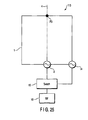
- FIGS. 20 to 22 collectively shows an eighth embodiment in which the technical idea of the present invention is applied to a loop antenna for a portable telephone.
- FIG. 20 shows the configuration of a loop antenna 109.
- FIG. 21 is a graph showing the relationship between the VSWR value at the power supply point and the frequency.
- FIG. 22 shows another construction relating to a modification of the loop antenna shown in FIG. 20.
- a short-circuiting line 10 is formed in each of the four corners of the looped line 1, and each short-circuiting line 10 is connected to the line 1 in a manner to cross the corner portion of the looped line 1. Because of the formation of the short-circuiting lines 10, an outer first loop having a large line length and an inner second loop having a small line length are formed in the loop antenna 109. In the loop antenna of the particular construction, an appreciably large difference in the line length is not generated between the outer first loop and the inner second loop. As a result, generated are two resonance frequencies that are close to each other.
- the resonance frequency corresponding to the outer loop having a large line length is close to the resonance frequency corresponding to the inner loop having a small line length, these two resonance frequencies are combined, with the result that the frequency characteristics having a large band width are imparted to the loop antenna, as shown in FIG. 21. It can be understood from the comparison with the frequency characteristics shown in FIG. 5 that the frequency characteristics shown in FIG. 21 have a large band width.
- FIG. 22 shows the configuration of a loop antenna 110 corresponding to a modification of the loop antenna shown in FIG. 20.
- the upper portion and the lower portion of the line 1 are folded toward the inner region of the loop antenna 110, and the right side section and the left side section are erected on a plane including the upper portion and the lower portion of the line 1, as in the loop antenna shown in FIG. 10.
- the entire length of the line 1 starting from the power supply point 2, passing through the half point 3, and ending in the power supply point 2 is set at the length equal to two wavelengths of a prescribed frequency, and the half point 3 is positioned one wavelength apart from the power supply point 2.
- short-circuiting lines 10 are arranged in four L-shaped lines arranged on a plane including the upper portion and the lower portion of the line 1 so as to achieve the short-circuiting in the L-shaped lines.
- the two resonance frequencies are close to each other so as to make it possible to achieve a large band width. Also, by folding a part of the line 1, the size of the entire loop antenna can be diminished while securing a prescribed length of the line 1. It follows that it is possible to realize a small loop antenna and a small portable telephone.
- FIG. 23 shows the configuration of a loop antenna 111 according to a ninth embodiment, in which the technical idea of the present invention is applied to a loop antenna for a portable telephone.
- a short-circuiting element is not included in the loop antenna 111.
- a parasitic element 11 is arranged outside of the line 1 such that the parasitic element 11 extends in parallel to the lower side section of the line 1.
- the line length of the parasitic element 11 is substantially equal to 1/2 wavelength of a desired resonance frequency differing from the resonance frequency of the line 1.
- the both edge portions of the parasitic element 11 are folded upward.
- the VSWR as viewed from the power supply point generates different resonance frequencies like the VSWR for the fifth embodiment of the present invention shown in FIG. 14.
- a parasitic element 11a is arranged inside the line 1 as denoted by a dotted line in FIG. 23 in place of the parasitic element 11 arranged outside the line 1, it is possible to obtain the similar characteristics.
- the loop antenna 111 according to the ninth embodiment of the present invention has two resonance frequencies so as to make it possible to incorporate the loop antenna 111 in a portable telephone of a dual mode of two frequencies.
- FIGS. 24 and 25 collectively show a tenth embodiment, in which the technical idea of the present invention is applied to a loop antenna for a portable telephone.
- FIG. 24 shows the configuration of a loop antenna 112
- FIG. 25 shows the construction relating to a modification of the loop antenna 112 shown in FIG. 24.
- a power supply point is mounted to a printing substrate 13 outside the line 1, and a power supply line 12 is connected to the power supply point. Under this condition, an electromagnetic coupling is achieved between the tip portion of the power supply line 12 and the line 1 of the loop antenna 112 shown in FIG. 24 so as to achieve the power supply.
- the power supply line 12 is arranged on an imaginary line extending from the right side section of the line 1, and the power supply point 2 is positioned on the printing substrate 13 arranged on the imaginary line extending from the right side of the line 1.
- the length of the power supply line 12 is defined to be an odd number times as long as about 1/4 wavelength of the resonance frequency of the line 1. Also, the distance of the path between a point P0, which is an intersection between the line 1 and the symmetric line 4, and the power supply point, the path including the electromagnetic coupling point, is defined to be an integer number times as long as about 1/2 wavelength.
- an electric power is supplied from the power supply point 2 to the line 1 through the power supply line 12.
- the driving power is rendered maximum at the power supply point 2 and the point P0 that is apart from the power supply point 2 by 1/2 wavelength.
- the driving power is also rendered maximum at each of points P1 and P2, which are apart from the point P0 by 1/2 wavelength, and at point P3 which is apart from any of the points P1 and P2 by 1/2 wavelength.
- the driving current vector similar to that described previously with reference to FIG. 3 is generated in the loop antenna, with the result that the current distribution on the right side and the current distribution on the left side are rendered symmetric in the loop antenna with respect to the symmetric line 4. It follows that a null can be formed in the radiation characteristics in the direction toward the user of the portable telephone.
- the power supply point can be arranged freely even in the case where there is a restriction in respect of the configuration of the portable telephone so as to enhance the degree of freedom of the design.
- FIG. 25 shows the configuration of a loop antenna 113 according to an eleventh embodiment, in which the technical idea of the present invention is applied to the loop antenna for a portable telephone.
- a power supply point 14 is formed on, for example, the lower right corner of the line 1 in addition to the power supply point 2 formed on the symmetric line 4 as in FIG. 2.
- the power supply points 2 and 14 are selected by a switch 15 arranged between each of the power supply points 2, 14 and an RF 16.
- the power supply point 2 on the symmetric line 4 is selected by the switch 15 in the loop antenna 113 shown in FIG. 25, the driving current vectors on the right side and the left side, which are in symmetry with respect to the symmetric line 4, are generated on the line of the loop antenna 113.
- the radiation characteristics are set at a null in a direction perpendicular to the plane of the loop antenna 113, i.e., in the direction toward the user of the portable telephone.
- the driving current vectors that are in symmetry with respect to the diagonal line passing through the power supply point 14 are generated in the line 1.
- the radiation characteristics caused by the driving current vectors are rendered different from the radiation characteristics caused by the driving current vectors shown in FIG. 3. As a matter of fact, the radiation characteristics are naturally rendered different. In this fashion, in the case where the loop antenna includes a plurality of power supply points, it is possible to select a desired directivity by switching the power supply point by operating the switch so as to switch the radiation characteristics.
- an exclusive RF circuit for the power supply point 2 and another exclusive RF circuit (not shown) for the power supply point 14 in place of mounting the switch 15 so as to selectively drive these two RF circuits.
- an exclusive RF circuit for the power supply point 2
- another exclusive RF circuit for the power supply point 14
- FIG. 26 shows the configuration of a loop antenna apparatus according to a twelfth embodiment, in which the technical idea of the present invention is applied to a loop antenna for a portable telephone.
- a plurality of loop antennas e.g., three loop antennas 114a, 114b, 114c each including a line and a power supply point.
- RF circuits 17a to 17c and AD converters 18a to 18c are connected to the power supply points 2a, 2b, 2c of the loop antennas 114a, 114b, 114c, respectively.
- a signal processing section 19 is commonly connected to the AD converters 18a to 18c.
- the magnitude of the driving current for each loop antenna is controlled so as to make the magnitudes of the radiation characteristics different from each other.
- a plurality of different radiation characteristics are combined so as to make it possible to change the directivity of the entire antenna apparatus comprising a plurality of loop antennas.
- a plurality of radiation characteristics can be combined by changing the arrangement among a plurality of loop antennas so as to change the directivity of the antenna apparatus including a plurality of loop antennas. It is also possible to achieve a multi-resonance by allowing a plurality of loop antennas to resonate with each other under frequencies differing from each other, or it is possible to enlarge the band width by allowing a plurality of loop antennas to resonate with each other under frequencies close to each other.
- FIG. 27 shows the configuration of a loop antenna 115 according to a thirteenth embodiment, in which the technical idea of the present invention is applied to the loop antenna for a portable telephone and also shows the distribution of the driving current.
- the line 1 is formed such that parallel lines on the YZ plane each having a length equal to 1/4 wavelength extend obliquely upward and obliquely downward from the upper right portion and the lower left portion of the line 1, respectively.
- the line length of each of the right side portion, the left side portion, the upper side portion and the lower side portion of the line 1 is set at a length equal to 1/4 wavelength.
- the entire length of the line 1 is equal to two wavelengths (1/4 wavelength ⁇ 8).
- the power supply point 2 is arranged at the intersection between the right side section and the lower side section of the line 1.
- the line length between the power supply point 2 and point P3 positioned on the diagonal line passing through the power supply point 2 is equal to one wavelength on each of the right side and the left side. It should be noted that the line 1 is arranged in symmetry with respect to the symmetric line 4 (diagonal line noted above) extending through the power supply point 2 and the point P3 noted above.
- driving current vectors 1h, 1b, 1a, 1f, 1e, 1c, 1d and 1g are generated in the counterclockwise direction about the power supply point 2.
- the relationship between the power supply point 2 and the driving current vectors shown in FIG. 3 is maintained in these driving current vectors shown in FIG. 27 so as to shift these driving current vectors.
- the driving current vectors 1h and 1e are opposite to each other in phase if viewed leftward and rightward from the Z-axis, as shown in FIG. 27. It follows that the radiation pattern of the electromagnetic field on the XY plane is constricted in the front-rear direction in the central portion in the right-left direction like the radiation pattern shown in FIG. 4, with the result that a null is generated in the front-rear direction in the central portion in the right-left direction.
- a null of the radiation characteristics is formed in a direction perpendicular to the plane of the loop antenna, i.e., in the direction toward the user of the portable telephone. It follows that the radiation efficiency of the antenna is improved without giving rise to the mismatch loss and the dielectric loss caused by the human body.
- each embodiment of the present invention is described independently in the present specification. However, it is possible to combine a plurality of embodiments of the present invention so as to operate the loop antenna as a loop antenna having a different construction. Also, each of the embodiments described above is directed to the case where the loop antenna of the present invention is used in a portable telephone. However, it is also possible to use the loop antenna of the present invention in a mobile communication terminal such as PDA.
- a null of the radiation characteristics is formed in a direction perpendicular to the plane of the loop antenna, i.e., in the direction toward the user of the portable telephone, so as to make it possible to improve the radiation efficiency of the antenna during the telephone conversation. It is also possible to miniaturize the loop antenna.
Landscapes
- Engineering & Computer Science (AREA)
- Computer Networks & Wireless Communication (AREA)
- Support Of Aerials (AREA)
- Telephone Set Structure (AREA)
- Details Of Aerials (AREA)
Applications Claiming Priority (2)
| Application Number | Priority Date | Filing Date | Title |
|---|---|---|---|
| JP2004005750 | 2004-01-13 | ||
| JP2004005750A JP3791923B2 (ja) | 2004-01-13 | 2004-01-13 | 無線通信端末 |
Publications (2)
| Publication Number | Publication Date |
|---|---|
| EP1555717A1 true EP1555717A1 (de) | 2005-07-20 |
| EP1555717B1 EP1555717B1 (de) | 2007-04-18 |
Family
ID=34616845
Family Applications (1)
| Application Number | Title | Priority Date | Filing Date |
|---|---|---|---|
| EP04022800A Ceased EP1555717B1 (de) | 2004-01-13 | 2004-09-24 | Mobiles Kommunikationsendgerät mit Schleifenantenne |
Country Status (4)
| Country | Link |
|---|---|
| US (1) | US7158820B2 (de) |
| EP (1) | EP1555717B1 (de) |
| JP (1) | JP3791923B2 (de) |
| DE (1) | DE602004005958D1 (de) |
Cited By (26)
| Publication number | Priority date | Publication date | Assignee | Title |
|---|---|---|---|---|
| WO2007060792A1 (ja) | 2005-11-22 | 2007-05-31 | Murata Manufacturing Co., Ltd. | コイルアンテナおよび携帯電子機器 |
| EP1973192A1 (de) * | 2007-03-23 | 2008-09-24 | Research In Motion Limited | Antennenvorrichtung und entsprechendes Verfahren für ein Multiband-Radiogerät |
| US7456798B2 (en) | 2006-06-28 | 2008-11-25 | Freescale Semiconductor, Inc | Stacked loop antenna |
| CN101453057A (zh) * | 2007-12-05 | 2009-06-10 | 天线直通股份有限公司 | 具有天线元件和反射器的天线组件 |
| US7629932B2 (en) | 2007-03-23 | 2009-12-08 | Research In Motion Limited | Antenna apparatus, and associated methodology, for a multi-band radio device |
| WO2010036279A1 (en) * | 2007-11-28 | 2010-04-01 | Qualcomm Incorporated | Wireless power range increase using parasitic antennas |
| EP2232639A1 (de) * | 2007-12-05 | 2010-09-29 | Antennas Direct, Inc. | Antennenbaugruppen mit antennenelementen und reflektoren |
| US7990335B2 (en) | 2007-12-05 | 2011-08-02 | Antennas Direct, Inc. | Antenna assemblies with antenna elements and reflectors |
| WO2012049473A3 (en) * | 2010-10-15 | 2012-12-13 | Antenova Limited | A loop antenna for mobile handset and other applications |
| US8368607B2 (en) | 2007-12-05 | 2013-02-05 | Antennas Direct, Inc. | Antenna assemblies with antenna elements and reflectors |
| EP2802037A1 (de) * | 2013-04-30 | 2014-11-12 | Starkey Laboratories, Inc. | Kleine Schleifenantenne mit Kurzschlussleitern für Hörgeräte |
| US8994600B2 (en) | 2007-12-05 | 2015-03-31 | Antennas Direct, Inc. | Antenna assemblies with tapered loop antenna elements |
| US9761935B2 (en) | 2015-09-02 | 2017-09-12 | Antennas Direct, Inc. | HDTV antenna assemblies |
| USD804459S1 (en) | 2008-02-29 | 2017-12-05 | Antennas Direct, Inc. | Antennas |
| USD809490S1 (en) | 2008-02-29 | 2018-02-06 | Antennas Direct, Inc. | Antenna |
| US10128575B2 (en) | 2015-09-02 | 2018-11-13 | Antennas Direct, Inc. | HDTV antenna assemblies |
| USD867347S1 (en) | 2008-02-29 | 2019-11-19 | Antennas Direct, Inc. | Antenna |
| USD868045S1 (en) | 2008-02-29 | 2019-11-26 | Antennas Direct, Inc. | Antenna |
| US10615501B2 (en) | 2007-12-05 | 2020-04-07 | Antennas Direct, Inc. | Antenna assemblies with tapered loop antenna elements |
| USD881172S1 (en) | 1975-11-03 | 2020-04-14 | Antennas Direct, Inc. | Antenna and base stand |
| USD883265S1 (en) | 2008-02-29 | 2020-05-05 | Antennas Direct, Inc. | Antenna |
| USD883264S1 (en) | 2008-02-29 | 2020-05-05 | Antennas Direct, Inc. | Antenna |
| USD888694S1 (en) | 2008-02-29 | 2020-06-30 | Antennas Direct, Inc. | Antenna |
| US10957979B2 (en) | 2018-12-06 | 2021-03-23 | Antennas Direct, Inc. | Antenna assemblies |
| USD920962S1 (en) | 2008-02-29 | 2021-06-01 | Antennas Direct, Inc. | Base stand for antenna |
| US11929562B2 (en) | 2007-12-05 | 2024-03-12 | Antennas Direct, Inc. | Antenna assemblies with tapered loop antenna elements |
Families Citing this family (24)
| Publication number | Priority date | Publication date | Assignee | Title |
|---|---|---|---|---|
| KR100612142B1 (ko) * | 2004-01-16 | 2006-08-11 | 주식회사 케이티프리텔 | 이동통신 단말을 이용한 공중선계 원격 측정 감시 장치 및그 방법 |
| JP4679950B2 (ja) * | 2005-04-11 | 2011-05-11 | 日本アンテナ株式会社 | ループアンテナ |
| JP2007067884A (ja) * | 2005-08-31 | 2007-03-15 | Yokowo Co Ltd | アンテナ |
| JP2007228326A (ja) * | 2006-02-24 | 2007-09-06 | Omron Corp | ループアンテナ、およびrfidタグ |
| JP2008085587A (ja) * | 2006-09-27 | 2008-04-10 | Dx Antenna Co Ltd | 放射器およびそれを備えるアンテナ装置 |
| JP4893889B2 (ja) * | 2007-07-09 | 2012-03-07 | 勝部 利夫 | 2重ループアンテナ |
| TWI381577B (zh) * | 2007-07-18 | 2013-01-01 | Fujitsu Ltd | 無線射頻識別標籤及無線射頻識別標籤之製造方法 |
| KR101102122B1 (ko) | 2007-07-18 | 2012-01-02 | 후지쯔 가부시끼가이샤 | 무선 태그 및 무선 태그의 제조 방법 |
| US7994986B2 (en) * | 2007-08-17 | 2011-08-09 | Ethertronics, Inc. | Antenna with near field deflector |
| US20090051614A1 (en) * | 2007-08-20 | 2009-02-26 | Hang Wong | Folded dipole antenna |
| JP5267463B2 (ja) * | 2008-03-03 | 2013-08-21 | 株式会社村田製作所 | 無線icデバイス及び無線通信システム |
| JP5319313B2 (ja) * | 2008-08-29 | 2013-10-16 | 峰光電子株式会社 | ループアンテナ |
| EP2518828A4 (de) * | 2009-12-24 | 2015-04-01 | Asahi Glass Co Ltd | Rfid-etikett |
| USD664126S1 (en) | 2010-08-26 | 2012-07-24 | Antennas Direct, Inc. | Antenna |
| JP5640817B2 (ja) * | 2011-02-28 | 2014-12-17 | Tdk株式会社 | アンテナ装置 |
| JP5731300B2 (ja) * | 2011-07-12 | 2015-06-10 | Dxアンテナ株式会社 | アンテナ装置 |
| KR101347993B1 (ko) * | 2011-10-25 | 2014-01-08 | 주식회사 에이스테크놀로지 | 단말기 하우징에 결합되는 안테나 |
| TW201526594A (zh) * | 2013-12-27 | 2015-07-01 | Quanta Comp Inc | 穿戴式裝置 |
| JP5737459B2 (ja) * | 2014-05-20 | 2015-06-17 | 住友電気工業株式会社 | 双ループアンテナ |
| JPWO2016117092A1 (ja) * | 2015-01-22 | 2017-04-27 | 株式会社東芝 | アンテナ装置及び無線装置 |
| EP3293819A1 (de) * | 2016-09-09 | 2018-03-14 | Thomson Licensing | Antennenspeisungsvorrichtung zur speisung einer in einer elektronischen vorrichtung integrierten antenne |
| US10575623B2 (en) * | 2018-06-29 | 2020-03-03 | Sephora USA, Inc. | Color capture system and device |
| JP7324858B2 (ja) | 2019-10-23 | 2023-08-10 | Fcnt株式会社 | アンテナ装置および無線通信装置 |
| CN115528434A (zh) * | 2022-10-21 | 2022-12-27 | 嘉兴诺艾迪通信科技有限公司 | 一种具有脊端加载的超宽带双脊喇叭天线 |
Citations (3)
| Publication number | Priority date | Publication date | Assignee | Title |
|---|---|---|---|---|
| EP0933832A2 (de) * | 1998-01-30 | 1999-08-04 | Matsushita Electric Industrial Co., Ltd. | Eingebaute Antenne für Funkübertragungsendgeräte |
| US6236368B1 (en) * | 1997-09-10 | 2001-05-22 | Rangestar International Corporation | Loop antenna assembly for telecommunication devices |
| US20030071757A1 (en) * | 2001-10-12 | 2003-04-17 | Murata Manufacturing Co., Ltd. | Loop antenna, surface-mounted antenna and communication equipment having the same |
Family Cites Families (16)
| Publication number | Priority date | Publication date | Assignee | Title |
|---|---|---|---|---|
| JPS5214334A (en) | 1975-07-25 | 1977-02-03 | Denki Kogyo Kk | Broadband loop antenna |
| JPS5462641A (en) | 1977-10-11 | 1979-05-19 | Robertshaw Controls Co | Thermostat |
| US6064343A (en) * | 1993-04-05 | 2000-05-16 | Crowley; Robert J | Antenna coupling arrangement |
| JPH08321719A (ja) | 1995-03-22 | 1996-12-03 | Kubota Corp | 受信用面状アンテナ装置 |
| JP4108246B2 (ja) | 2000-02-23 | 2008-06-25 | 日本電業工作株式会社 | ループアンテナ |
| JP2001326514A (ja) * | 2000-05-18 | 2001-11-22 | Sharp Corp | 携帯無線機用アンテナ |
| AU2001268114A1 (en) | 2000-05-31 | 2001-12-11 | Bae Systems Information And Electronic Systems Integration, Inc. | Narrow-band, crossed-element, offset-tuned dual band, dual mode meander line loaded antenna |
| JP4510244B2 (ja) | 2000-07-19 | 2010-07-21 | パナソニック株式会社 | アンテナ装置 |
| US6351629B1 (en) * | 2000-09-12 | 2002-02-26 | Dieceland Technologies Corp. | Compact modular wireless telephone |
| US20030096637A1 (en) * | 2001-11-09 | 2003-05-22 | Keller Walter John | Loop antenna formed of multiple concentric irregular loops |
| JP2003188631A (ja) | 2001-12-17 | 2003-07-04 | Sansei Denki Kk | 反射板付きループアンテナおよび同構成方法 |
| US6781551B2 (en) * | 2002-08-06 | 2004-08-24 | Phonak Ag | Hand-held transmitter and/or receiver unit |
| JP3824579B2 (ja) | 2002-12-19 | 2006-09-20 | 株式会社東芝 | アンテナ装置、携帯無線通信装置及び接続部材 |
| JP3848328B2 (ja) * | 2004-01-13 | 2006-11-22 | 株式会社東芝 | アンテナおよびこのアンテナを搭載した無線通信装置 |
| JP3790249B2 (ja) * | 2004-01-13 | 2006-06-28 | 株式会社東芝 | ループアンテナ及びループアンテナを備えた無線通信機 |
| JP4042702B2 (ja) * | 2004-01-30 | 2008-02-06 | ソニー株式会社 | 携帯型情報処理端末装置 |
-
2004
- 2004-01-13 JP JP2004005750A patent/JP3791923B2/ja not_active Expired - Fee Related
- 2004-09-24 US US10/948,876 patent/US7158820B2/en not_active Expired - Fee Related
- 2004-09-24 EP EP04022800A patent/EP1555717B1/de not_active Ceased
- 2004-09-24 DE DE602004005958T patent/DE602004005958D1/de not_active Expired - Lifetime
Patent Citations (3)
| Publication number | Priority date | Publication date | Assignee | Title |
|---|---|---|---|---|
| US6236368B1 (en) * | 1997-09-10 | 2001-05-22 | Rangestar International Corporation | Loop antenna assembly for telecommunication devices |
| EP0933832A2 (de) * | 1998-01-30 | 1999-08-04 | Matsushita Electric Industrial Co., Ltd. | Eingebaute Antenne für Funkübertragungsendgeräte |
| US20030071757A1 (en) * | 2001-10-12 | 2003-04-17 | Murata Manufacturing Co., Ltd. | Loop antenna, surface-mounted antenna and communication equipment having the same |
Non-Patent Citations (2)
| Title |
|---|
| LI R L ET AL: "Pattern shaping using a reactively loaded wire loop antenna", IEE PROCEEDINGS H. MICROWAVES, ANTENNAS & PROPAGATION, INSTITUTION OF ELECTRICAL ENGINEERS. STEVENAGE, GB, vol. 148, no. 3, 11 June 2001 (2001-06-11), pages 203 - 208, XP006016880, ISSN: 0950-107X * |
| NAKANO H ET AL: "A LOW-PROFILE CONICAL BEAM LOOP ANTENNA WITH AN ELECTROMAGNETICALLYCOUPLED FEED SYSTEM", IEEE TRANSACTIONS ON ANTENNAS AND PROPAGATION, IEEE INC. NEW YORK, US, vol. 48, no. 12, 1 December 2000 (2000-12-01), pages 1864 - 1866, XP001005155, ISSN: 0018-926X * |
Cited By (51)
| Publication number | Priority date | Publication date | Assignee | Title |
|---|---|---|---|---|
| USD881172S1 (en) | 1975-11-03 | 2020-04-14 | Antennas Direct, Inc. | Antenna and base stand |
| US7978146B2 (en) | 2005-11-22 | 2011-07-12 | Murata Manufacturing Co., Ltd. | Coil antenna and portable electronic apparatus |
| WO2007060792A1 (ja) | 2005-11-22 | 2007-05-31 | Murata Manufacturing Co., Ltd. | コイルアンテナおよび携帯電子機器 |
| CN101278439B (zh) * | 2005-11-22 | 2013-06-26 | 株式会社村田制作所 | 线圈天线及便携式电子设备 |
| US7456798B2 (en) | 2006-06-28 | 2008-11-25 | Freescale Semiconductor, Inc | Stacked loop antenna |
| EP1973192A1 (de) * | 2007-03-23 | 2008-09-24 | Research In Motion Limited | Antennenvorrichtung und entsprechendes Verfahren für ein Multiband-Radiogerät |
| US7629932B2 (en) | 2007-03-23 | 2009-12-08 | Research In Motion Limited | Antenna apparatus, and associated methodology, for a multi-band radio device |
| WO2010036279A1 (en) * | 2007-11-28 | 2010-04-01 | Qualcomm Incorporated | Wireless power range increase using parasitic antennas |
| US8766483B2 (en) | 2007-11-28 | 2014-07-01 | Qualcomm Incorporated | Wireless power range increase using parasitic antennas |
| EP2267842A1 (de) * | 2007-12-05 | 2010-12-29 | Antennas Direct, Inc. | Antennenanordnung mit Antennenelementen und -reflektoren |
| US7990335B2 (en) | 2007-12-05 | 2011-08-02 | Antennas Direct, Inc. | Antenna assemblies with antenna elements and reflectors |
| US11929562B2 (en) | 2007-12-05 | 2024-03-12 | Antennas Direct, Inc. | Antenna assemblies with tapered loop antenna elements |
| US8368607B2 (en) | 2007-12-05 | 2013-02-05 | Antennas Direct, Inc. | Antenna assemblies with antenna elements and reflectors |
| US11024968B2 (en) | 2007-12-05 | 2021-06-01 | Antennas Direct, Inc. | Antenna assemblies with tapered loop antenna elements |
| US10615501B2 (en) | 2007-12-05 | 2020-04-07 | Antennas Direct, Inc. | Antenna assemblies with tapered loop antenna elements |
| EP2232639A4 (de) * | 2007-12-05 | 2010-11-17 | Antennas Direct Inc | Antennenbaugruppen mit antennenelementen und reflektoren |
| EP2232639A1 (de) * | 2007-12-05 | 2010-09-29 | Antennas Direct, Inc. | Antennenbaugruppen mit antennenelementen und reflektoren |
| US8994600B2 (en) | 2007-12-05 | 2015-03-31 | Antennas Direct, Inc. | Antenna assemblies with tapered loop antenna elements |
| CN101453057A (zh) * | 2007-12-05 | 2009-06-10 | 天线直通股份有限公司 | 具有天线元件和反射器的天线组件 |
| USD888694S1 (en) | 2008-02-29 | 2020-06-30 | Antennas Direct, Inc. | Antenna |
| USD883265S1 (en) | 2008-02-29 | 2020-05-05 | Antennas Direct, Inc. | Antenna |
| USD918879S1 (en) | 2008-02-29 | 2021-05-11 | Antennas Direct, Inc. | Antenna |
| USD918187S1 (en) | 2008-02-29 | 2021-05-04 | Antennas Direct, Inc. | Antenna |
| USD804459S1 (en) | 2008-02-29 | 2017-12-05 | Antennas Direct, Inc. | Antennas |
| USD809490S1 (en) | 2008-02-29 | 2018-02-06 | Antennas Direct, Inc. | Antenna |
| USD928751S1 (en) | 2008-02-29 | 2021-08-24 | Antennas Direct, Inc. | Antenna |
| USD931260S1 (en) | 2008-02-29 | 2021-09-21 | Antennas Direct, Inc. | Antenna |
| USD867347S1 (en) | 2008-02-29 | 2019-11-19 | Antennas Direct, Inc. | Antenna |
| USD868045S1 (en) | 2008-02-29 | 2019-11-26 | Antennas Direct, Inc. | Antenna |
| USD868720S1 (en) | 2008-02-29 | 2019-12-03 | Antennas Direct, Inc. | Antenna |
| USD904358S1 (en) | 2008-02-29 | 2020-12-08 | Antennas Direct, Inc. | Antenna |
| USD902896S1 (en) | 2008-02-29 | 2020-11-24 | Antennas Direct, Inc. | Antenna |
| USD920962S1 (en) | 2008-02-29 | 2021-06-01 | Antennas Direct, Inc. | Base stand for antenna |
| USD883264S1 (en) | 2008-02-29 | 2020-05-05 | Antennas Direct, Inc. | Antenna |
| USD892096S1 (en) | 2008-02-29 | 2020-08-04 | Antennas Direct, Inc. | Antenna |
| USD888697S1 (en) | 2008-02-29 | 2020-06-30 | Antennas Direct, Inc. | Antenna |
| US9543650B2 (en) | 2010-10-15 | 2017-01-10 | Microsoft Technology Licensing, Llc | Loop antenna for mobile handset and other applications |
| CN103155281B (zh) * | 2010-10-15 | 2015-09-09 | 微软技术许可有限责任公司 | 用于移动手机及其他应用的回路天线 |
| US9502771B2 (en) | 2010-10-15 | 2016-11-22 | Microsoft Technology Licenseing, LLC | Loop antenna for mobile handset and other applications |
| US9948003B2 (en) | 2010-10-15 | 2018-04-17 | Microsoft Technology Licensing, Llc | Loop antenna for mobile handset and other applications |
| WO2012049473A3 (en) * | 2010-10-15 | 2012-12-13 | Antenova Limited | A loop antenna for mobile handset and other applications |
| EP3148000A1 (de) * | 2010-10-15 | 2017-03-29 | Microsoft Technology Licensing, LLC | Rahmenantenne für ein mobiltelefon und andere anwendungen |
| CN103155281A (zh) * | 2010-10-15 | 2013-06-12 | 微软公司 | 用于移动手机及其他应用的回路天线 |
| EP2802037A1 (de) * | 2013-04-30 | 2014-11-12 | Starkey Laboratories, Inc. | Kleine Schleifenantenne mit Kurzschlussleitern für Hörgeräte |
| US10743116B2 (en) | 2013-04-30 | 2020-08-11 | Starkey Laboratories, Inc. | Small loop antenna with shorting conductors for hearing assistance devices |
| US10693239B2 (en) | 2015-09-02 | 2020-06-23 | Antennas Direct, Inc. | HDTV antenna assemblies |
| US10128575B2 (en) | 2015-09-02 | 2018-11-13 | Antennas Direct, Inc. | HDTV antenna assemblies |
| US9761935B2 (en) | 2015-09-02 | 2017-09-12 | Antennas Direct, Inc. | HDTV antenna assemblies |
| US10957979B2 (en) | 2018-12-06 | 2021-03-23 | Antennas Direct, Inc. | Antenna assemblies |
| US11769947B2 (en) | 2018-12-06 | 2023-09-26 | Antennas Direct, Inc. | Antenna assemblies |
| US12095177B2 (en) | 2018-12-06 | 2024-09-17 | Antennas Direct, Inc. | Antenna assemblies |
Also Published As
| Publication number | Publication date |
|---|---|
| EP1555717B1 (de) | 2007-04-18 |
| US7158820B2 (en) | 2007-01-02 |
| US20050153755A1 (en) | 2005-07-14 |
| JP2005203877A (ja) | 2005-07-28 |
| JP3791923B2 (ja) | 2006-06-28 |
| DE602004005958D1 (de) | 2007-05-31 |
Similar Documents
| Publication | Publication Date | Title |
|---|---|---|
| EP1555717B1 (de) | Mobiles Kommunikationsendgerät mit Schleifenantenne | |
| JP4510244B2 (ja) | アンテナ装置 | |
| US7358906B2 (en) | Antenna device and mobile communication terminal equipped with antenna device | |
| JP3562512B2 (ja) | 表面実装型アンテナおよびそのアンテナを備えた通信装置 | |
| US7760150B2 (en) | Antenna assembly and wireless unit employing it | |
| US7830329B2 (en) | Composite antenna and portable terminal using same | |
| RU2517310C2 (ru) | Устройство радиосвязи, включающее петлевую антенну | |
| JP4171008B2 (ja) | アンテナ装置および携帯無線機 | |
| JP5327322B2 (ja) | アンテナモジュール | |
| US20020058483A1 (en) | Portable communiation terminal with reduced specific absorption rate | |
| TWI533637B (zh) | 在lte/gsm頻帶中用於mimo/多元化操作的lte天線對 | |
| JP3848328B2 (ja) | アンテナおよびこのアンテナを搭載した無線通信装置 | |
| JP5791961B2 (ja) | マルチアンテナ装置および通信機器 | |
| JP2008294635A (ja) | アンテナ装置及び携帯無線機 | |
| US20080316113A1 (en) | Folding Type Communication Terminal Device | |
| JP4925937B2 (ja) | アンテナ装置及び携帯無線装置 | |
| JP2004242165A (ja) | 携帯無線機 | |
| JP3824579B2 (ja) | アンテナ装置、携帯無線通信装置及び接続部材 | |
| JP5712784B2 (ja) | マルチアンテナ装置および通信機器 | |
| JP2004304705A (ja) | 無線装置 | |
| JP4881978B2 (ja) | アンテナ装置 | |
| JP2000315905A (ja) | アンテナ構造及びカード型無線端末 | |
| JP4830577B2 (ja) | アンテナ装置 | |
| JP2008283631A (ja) | 携帯無線機用のアンテナ装置及びそれを用いた携帯無線機 | |
| JP5286307B2 (ja) | アンテナおよび携帯無線端末 |
Legal Events
| Date | Code | Title | Description |
|---|---|---|---|
| PUAI | Public reference made under article 153(3) epc to a published international application that has entered the european phase |
Free format text: ORIGINAL CODE: 0009012 |
|
| 17P | Request for examination filed |
Effective date: 20040924 |
|
| AK | Designated contracting states |
Kind code of ref document: A1 Designated state(s): AT BE BG CH CY CZ DE DK EE ES FI FR GB GR HU IE IT LI LU MC NL PL PT RO SE SI SK TR |
|
| AX | Request for extension of the european patent |
Extension state: AL HR LT LV MK |
|
| AKX | Designation fees paid |
Designated state(s): DE FR GB |
|
| GRAP | Despatch of communication of intention to grant a patent |
Free format text: ORIGINAL CODE: EPIDOSNIGR1 |
|
| GRAS | Grant fee paid |
Free format text: ORIGINAL CODE: EPIDOSNIGR3 |
|
| GRAA | (expected) grant |
Free format text: ORIGINAL CODE: 0009210 |
|
| AK | Designated contracting states |
Kind code of ref document: B1 Designated state(s): DE FR GB |
|
| REF | Corresponds to: |
Ref document number: 602004005958 Country of ref document: DE Date of ref document: 20070531 Kind code of ref document: P |
|
| EN | Fr: translation not filed | ||
| PLBE | No opposition filed within time limit |
Free format text: ORIGINAL CODE: 0009261 |
|
| STAA | Information on the status of an ep patent application or granted ep patent |
Free format text: STATUS: NO OPPOSITION FILED WITHIN TIME LIMIT |
|
| 26N | No opposition filed |
Effective date: 20080121 |
|
| PG25 | Lapsed in a contracting state [announced via postgrant information from national office to epo] |
Ref country code: FR Free format text: LAPSE BECAUSE OF FAILURE TO SUBMIT A TRANSLATION OF THE DESCRIPTION OR TO PAY THE FEE WITHIN THE PRESCRIBED TIME-LIMIT Effective date: 20071214 Ref country code: DE Free format text: LAPSE BECAUSE OF FAILURE TO SUBMIT A TRANSLATION OF THE DESCRIPTION OR TO PAY THE FEE WITHIN THE PRESCRIBED TIME-LIMIT Effective date: 20070719 |
|
| PG25 | Lapsed in a contracting state [announced via postgrant information from national office to epo] |
Ref country code: FR Free format text: LAPSE BECAUSE OF FAILURE TO SUBMIT A TRANSLATION OF THE DESCRIPTION OR TO PAY THE FEE WITHIN THE PRESCRIBED TIME-LIMIT Effective date: 20070418 |
|
| GBPC | Gb: european patent ceased through non-payment of renewal fee |
Effective date: 20080924 |
|
| PG25 | Lapsed in a contracting state [announced via postgrant information from national office to epo] |
Ref country code: GB Free format text: LAPSE BECAUSE OF NON-PAYMENT OF DUE FEES Effective date: 20080924 |