EP1555660A1 - Aufzeichnungs-/Wiedergabegerät für optische Informationsträger - Google Patents
Aufzeichnungs-/Wiedergabegerät für optische Informationsträger Download PDFInfo
- Publication number
- EP1555660A1 EP1555660A1 EP04300712A EP04300712A EP1555660A1 EP 1555660 A1 EP1555660 A1 EP 1555660A1 EP 04300712 A EP04300712 A EP 04300712A EP 04300712 A EP04300712 A EP 04300712A EP 1555660 A1 EP1555660 A1 EP 1555660A1
- Authority
- EP
- European Patent Office
- Prior art keywords
- guide rod
- recording
- shaped portion
- tensioning element
- reproduction apparatus
- Prior art date
- Legal status (The legal status is an assumption and is not a legal conclusion. Google has not performed a legal analysis and makes no representation as to the accuracy of the status listed.)
- Withdrawn
Links
- 230000003287 optical effect Effects 0.000 title claims abstract description 26
- 230000005540 biological transmission Effects 0.000 claims abstract description 10
- 238000005452 bending Methods 0.000 claims abstract description 6
- 239000011324 bead Substances 0.000 claims description 12
- 238000010586 diagram Methods 0.000 description 10
- 230000001105 regulatory effect Effects 0.000 description 3
- 230000002411 adverse Effects 0.000 description 1
- 230000001419 dependent effect Effects 0.000 description 1
- 230000000284 resting effect Effects 0.000 description 1
- 230000000717 retained effect Effects 0.000 description 1
- 230000035945 sensitivity Effects 0.000 description 1
Images




Classifications
-
- G—PHYSICS
- G11—INFORMATION STORAGE
- G11B—INFORMATION STORAGE BASED ON RELATIVE MOVEMENT BETWEEN RECORD CARRIER AND TRANSDUCER
- G11B7/00—Recording or reproducing by optical means, e.g. recording using a thermal beam of optical radiation by modifying optical properties or the physical structure, reproducing using an optical beam at lower power by sensing optical properties; Record carriers therefor
- G11B7/08—Disposition or mounting of heads or light sources relatively to record carriers
- G11B7/085—Disposition or mounting of heads or light sources relatively to record carriers with provision for moving the light beam into, or out of, its operative position or across tracks, otherwise than during the transducing operation, e.g. for adjustment or preliminary positioning or track change or selection
-
- G—PHYSICS
- G11—INFORMATION STORAGE
- G11B—INFORMATION STORAGE BASED ON RELATIVE MOVEMENT BETWEEN RECORD CARRIER AND TRANSDUCER
- G11B7/00—Recording or reproducing by optical means, e.g. recording using a thermal beam of optical radiation by modifying optical properties or the physical structure, reproducing using an optical beam at lower power by sensing optical properties; Record carriers therefor
- G11B7/08—Disposition or mounting of heads or light sources relatively to record carriers
- G11B7/09—Disposition or mounting of heads or light sources relatively to record carriers with provision for moving the light beam or focus plane for the purpose of maintaining alignment of the light beam relative to the record carrier during transducing operation, e.g. to compensate for surface irregularities of the latter or for track following
- G11B7/095—Disposition or mounting of heads or light sources relatively to record carriers with provision for moving the light beam or focus plane for the purpose of maintaining alignment of the light beam relative to the record carrier during transducing operation, e.g. to compensate for surface irregularities of the latter or for track following specially adapted for discs, e.g. for compensation of eccentricity or wobble
- G11B7/0956—Disposition or mounting of heads or light sources relatively to record carriers with provision for moving the light beam or focus plane for the purpose of maintaining alignment of the light beam relative to the record carrier during transducing operation, e.g. to compensate for surface irregularities of the latter or for track following specially adapted for discs, e.g. for compensation of eccentricity or wobble to compensate for tilt, skew, warp or inclination of the disc, i.e. maintain the optical axis at right angles to the disc
-
- G—PHYSICS
- G11—INFORMATION STORAGE
- G11B—INFORMATION STORAGE BASED ON RELATIVE MOVEMENT BETWEEN RECORD CARRIER AND TRANSDUCER
- G11B7/00—Recording or reproducing by optical means, e.g. recording using a thermal beam of optical radiation by modifying optical properties or the physical structure, reproducing using an optical beam at lower power by sensing optical properties; Record carriers therefor
- G11B7/08—Disposition or mounting of heads or light sources relatively to record carriers
-
- G—PHYSICS
- G11—INFORMATION STORAGE
- G11B—INFORMATION STORAGE BASED ON RELATIVE MOVEMENT BETWEEN RECORD CARRIER AND TRANSDUCER
- G11B7/00—Recording or reproducing by optical means, e.g. recording using a thermal beam of optical radiation by modifying optical properties or the physical structure, reproducing using an optical beam at lower power by sensing optical properties; Record carriers therefor
- G11B7/08—Disposition or mounting of heads or light sources relatively to record carriers
- G11B7/09—Disposition or mounting of heads or light sources relatively to record carriers with provision for moving the light beam or focus plane for the purpose of maintaining alignment of the light beam relative to the record carrier during transducing operation, e.g. to compensate for surface irregularities of the latter or for track following
-
- G—PHYSICS
- G11—INFORMATION STORAGE
- G11B—INFORMATION STORAGE BASED ON RELATIVE MOVEMENT BETWEEN RECORD CARRIER AND TRANSDUCER
- G11B7/00—Recording or reproducing by optical means, e.g. recording using a thermal beam of optical radiation by modifying optical properties or the physical structure, reproducing using an optical beam at lower power by sensing optical properties; Record carriers therefor
- G11B7/08—Disposition or mounting of heads or light sources relatively to record carriers
- G11B7/09—Disposition or mounting of heads or light sources relatively to record carriers with provision for moving the light beam or focus plane for the purpose of maintaining alignment of the light beam relative to the record carrier during transducing operation, e.g. to compensate for surface irregularities of the latter or for track following
- G11B7/095—Disposition or mounting of heads or light sources relatively to record carriers with provision for moving the light beam or focus plane for the purpose of maintaining alignment of the light beam relative to the record carrier during transducing operation, e.g. to compensate for surface irregularities of the latter or for track following specially adapted for discs, e.g. for compensation of eccentricity or wobble
Definitions
- Recording and/or reproduction apparatus for optical recording media with means for parallel orientation of the scanning device with respect to the surface of the recording medium
- the invention relates to a recording and/or reproduction apparatus for optical recording media with means for parallel orientation of the scanning device with respect to the surface of the recording medium, the scanning device being arranged on a slide that is guided by means of a guide rod.
- a fixing and adjusting arrangement is provided which avoids to the greatest possible extent a force transmission to the guide rod that disadvantageously issues from the fixing or adjusting means.
- optical recording and/or reproduction apparatuses are CD or DVD players and corresponding recorders that are equipped by means of an optical scanning device, a so-called pick-up, to read data from an optical recording medium or to write data to the recording medium.
- the light beam, a laser beam, that reads the data of an optical recording medium or writes data to the optical recording medium is guided and focused on the track of the optical recording medium and has to be oriented perpendicularly with respect to the surface of the recording medium for optimum recording or reproduction of information.
- the optical scanning device is generally arranged on a slide that is moved parallel to the surface of the recording medium.
- One aspect of the invention is to specify means for fixing and adjusting the guide rod of the slide of an optical scanning device in a recording and/or reproduction apparatus for optical recording media which require a low outlay and nevertheless do not transmit to the guide rod forces which are necessary for the fixing and adjustment of the guide rod.
- the stress-free fixing and adjustment of the guide rod of the optical scanning device is necessary particularly on account of the high accuracy with which optical recording media, such as CD, DVD or Blu-Disc, have to be scanned.
- the track spacing of a DVD in accordance with the ECMA-267 Standard is just 0.74 ⁇ m and a shaft 80 mm long with a diameter of 3 mm has a flexure of 43 ⁇ m in the case of a force of 15 N acting in the end region at a distance of 3 mm. Therefore, use is made, for example, of stress-free fixing and adjusting devices which comprise at least one end element that receives the guide rod in a stress-free manner and can be adjusted in a stress-free manner by means of a screw and a spring. Such end elements disadvantageously require a high outlay both with regard to mounting and the number of individual parts.
- a fixing and adjusting arrangement comprising a tensioning element and an adjusting screw, which fix the guide rod on a shaped portion of the baseplate in an adjustable manner in a plane corresponding to the cross section of the guide rod.
- the tensioning element which is formed from a leaf spring, for example, wraps around the shaped portion of the baseplate and fixes the guide rod adjustably on the shaped portion of the baseplate.
- a tensioning element formed from a leaf spring has a bead that is arranged symmetrically and at an angle with respect to the adjusting direction of the adjusting screw that is provided for adjusting the guide rod.
- the angle at which the bead is arranged with respect to the adjusting direction of the adjusting screw is formed by a chamfer of the tensioning element formed in desk-like fashion.
- the fact that the bead of the tensioning element is arranged symmetrically and at an angle with respect to the adjusting direction of the adjusting screw means that, in a plane corresponding to the cross section of the guide rod, a linear fixing of the guide rod is achieved, thereby avoiding to the greatest possible extent a disadvantageous force transmission to the guide rod that leads to the bending of the guide rod.
- the tensioning element's bead which touches the guide rod tangentially, ensures a punctiform or linear fixing of the guide rod in the adjusting region of the guide rod.
- the bead, the adjusting screw and, if appropriate, a rib of the shaped portion of the baseplate are arranged in such a way that they form, in a plane corresponding to the cross section of the guide rod, a three-point fixing of the guide rod which avoids to the greatest possible extent the occurrence of bending forces issuing from the fixing of the guide rod.
- the tensioning element can be mounted, as a spring element that wraps around the shaped portion of the baseplate and fixes the guide rod in an adjustable manner, on the shaped portion of the baseplate with a low outlay.
- the tensioning element has a lug that engages into a cutout of the shaped portion for the purpose of preventing the tensioning element from being shifted.
- the shaped portion of the baseplate is provided as an angular piece, one limb of which receives the adjusting screw and the other limb of which forms a rib, for example, on which the guide rod is guided in the adjusting direction.
- the fixing and adjusting device requires a small number of individual parts and the mounting of the guide rod also requires a low outlay.
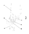
- Figure 1 shows the schematic diagram of a guide rod 4, which is held at one end by means of a fixing and adjusting device according to the invention, which comprises a tensioning element 1 having a bead 2, a shaped portion 5 of a baseplate 7 and an adjusting screw 3.
- the guide rod 4 is provided for guiding a movable slide which, in a recording and/or reproduction apparatus for optical recording media, carries a scanning device P provided for reading from or writing to a recording medium D illustrated in figure 2.
- the scanning device P generates a light or laser beam that has to be oriented perpendicularly onto the recording medium D in order to read or write information.
- the scanning device P For optical scanning of the recording medium D in its entire recording and/or reproduction region, the scanning device P is arranged on a movable slide that can be shifted parallel to the recording medium D in order to orient the laser beam perpendicularly onto the recording medium D.
- the parallel guidance of the scanning device P has to be provided with high accuracy since even slight deviations adversely affect the recording and/or reproduction on account of the optical scanning and the small dimensions of the information track of the recording medium D.
- the optical scanning device P generally has a fine drive and numerous servo regulating circuits for high-precision tracking and focusing of the laser beam and, if appropriate, also for orienting the laser beam perpendicularly onto the recording medium D.
- the fine drive and the servo regulating circuits are provided, in particular, in order to compensate for deviations of the recording medium D, which rotates on a disc turntable T, from a predetermined plane. Deviations with respect to said plane that issue from the guidance of the scanning device P already disadvantageously restrict the regulating range that can be provided for deviations of the recording medium D from the predetermined plane.
- Recording and/or reproduction apparatuses for optical recording media therefore have adjusting means that are used to set, for the purpose of orienting the scanning beam perpendicularly onto the recording medium D in the entire possible recording and/or reproduction region of the recording medium D, a parallel guidance of the scanning device P with respect to the recording medium D or a parallel orientation of the recording medium D with respect to a plane formed by the range of movement of the scanning device P.
- adjusting means that are used to set, for the purpose of orienting the scanning beam perpendicularly onto the recording medium D in the entire possible recording and/or reproduction region of the recording medium D, a parallel guidance of the scanning device P with respect to the recording medium D or a parallel orientation of the recording medium D with respect to a plane formed by the range of movement of the scanning device P.
- For parallel orientation of the recording medium D with respect to a plane formed by the range of movement of the scanning device P it is also possible to adjust the motor MT carrying the disc turntable T of the recording medium D on its spindle.
- the motor MT and the guide rod 4 on which the scanning device P is guided are arranged on a baseplate 7 such that corresponding adjustment can be carried out.
- the distance between the fixing and adjusting means of the motor MT is smaller than the range over which the scanning device P is moved, it is advantageous, for uncomplicated adjustment, to orient or adjust the guide rod 4 or the scanning device P with respect to the recording medium D.
- a fixing and adjusting device for the guide rod 4 is intended to have a small number of individual parts and mounting and adjustment are intended to be made possible with a low outlay, a solution illustrated in figure 3 has already been proposed, which essentially comprises a helical spring S that presses the guide rod 4 - guided in an opening O - against an adjusting screw 3.
- the helical spring S is fixed to a web W of the baseplate 7.
- a relatively low force of 15 N that acts on the guide rod 4 at a distance of just 3 mm from the clamping location leads to a flexure of the guide rod 4 by 43 ⁇ m if a customary guide rod 4 having an effective length of 80 mm and a diameter of 3 mm is used.
- the fixing and adjusting device illustrated in the figures with the exception of figure 3 is provided, which is used to orient the scanning device P parallel to the recording medium D.
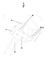
- a disadvantageous force transmission issuing from the means required for fixing the guide rod 4 is avoided to the greatest possible extent by means of the fixing and adjusting device illustrated in perspective view in figure 4 by virtue of the fact that the fixing and adjusting means are arranged in a line or a plane corresponding to the cross section of the guide rod 4.
- This line L is specified in figure 5 which forms, in the plan view illustrated, the center line of the fixing and adjusting device according to the invention.
- a tensioning element 1 with a bead 2 which is arranged in such a way that the center of its longest extent forms with the center point of the adjusting screw 3 a plane corresponding to the cross section of the guide rod 4.
- the linear orientation of the fixing of guide rod 4 is not altered even during the adjustment of the guide rod 4 for parallel orientation of the scanning device P with respect to the surface of the recording medium D.
- the guide rod 4 is adjusted by the adjusting screw 3 being correspondingly screwed in or out, a parallel orientation of the guide rod 4 with respect to the surface of the recording medium D being established by means of a collimator in a known manner.
- the collimator is an optical measuring device that determines the position of an object with respect to a predetermined position, as a result of which it is suitable in particular for adjustment.
- Screwing the adjusting screw 3 into or out of a threaded hole of the shaped portion 5 of the baseplate 7 raises or lowers the guide rod 4, as a result of which the distance between the guide rod 4 and the surface of the recording medium D is correspondingly reduced or increased.
- the tensioning element 1 that presses the guide rod 4 resiliently onto the end face of the adjusting screw 3 is extended by screwing in the adjusting screw 3 and fixedly clamps the guide rod 4 on the baseplate 7 or on the shaped portion 5 of the baseplate 7.
- the shaped portion 5 of the baseplate 7 is provided as an angular piece whose limbs form, with the end face of the adjusting screw 3, which may also be formed in pointed fashion, and with a rib R of the shaped portion 5, bearing or resting areas of the guide rode 4.
- the rib R is likewise formed in such a way that its center line corresponds to the line L illustrated in figure 5, so that a three-point clamping of the guide rod 4 that runs perpendicularly to the guide rod 4 is formed with the bead 2 of the tensioning element 1, the rib R and the adjusting screw 3.
- the rib R or a bearing area of the guide rod 4 that is formed by a limb of the shaped portion 5 is arranged approximately perpendicular, and the limb of the shaped portion 5 that receives the adjusting screw 3 is arranged approximately parallel, to the surface of the recording medium D, so that a distance directed essentially perpendicular to the recording medium D is set by means of the adjusting screw 3.
- a tensioning element 1 corresponding to the exemplary embodiment illustrated is produced from a leaf spring and embraces both the guide rod 4 and the shaped portion 5 in clip-like fashion.
- the tensioning element 1 is formed in desk-like fashion and has a chamfer that carries the bead 2 and is directed both at the rib R and at the end face of the adjusting screw 3.
- the tensioning element 1 is provided in self-retaining fashion, so that no further fixing elements are necessary, and for this purpose has at one end a lug N engaging into a cutout 6 of the shaped portion 5.
- the other end of the tensioning element 1 engages behind the angle formed by the limbs of the shaped portion 5.
- the guide rod 4 is retained both at the rib R and on the end face of the adjusting screw 3.
- the lug N of the tensioning element 1 is partly withdrawn from the cutout 6 of the shaped portion 5 when the adjusting screw 3 is screwed in.
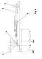
- the exploded illustration of the fixing and adjusting device according to the invention as illustrated in figure 8 shows that, besides the adjusting screw 3 that is always necessary, only a tensioning element 1 is necessary in order to fix the guide rod 4 on the shaped portion 5 of the baseplate 7 in an adjustable manner.
- a mandrel S formed by the shaped portion 5 is additionally provided.
- the fixing and adjusting arrangement is provided at least once at that end of the guide rod 4 which is the furthest away from the spindle of the disc turntable T.
- the other end of the guide rod 4 is fixed in a known manner by means of a fixing screw F on the baseplate 7, as illustrated in Figure 1.
- the illustration shows a gear mechanism G that is used to move the scanning device P, as illustrated in figure 2, in a manner driven by a motor MG.
Landscapes
- Moving Of The Head For Recording And Reproducing By Optical Means (AREA)
- Moving Of Heads (AREA)
Applications Claiming Priority (2)
| Application Number | Priority Date | Filing Date | Title |
|---|---|---|---|
| DE10358254A DE10358254A1 (de) | 2003-12-11 | 2003-12-11 | Aufzeichnungs- und/oder Wiedergabegerät für optische Aufzeichnungsträger mit Mitteln zum parallelen Ausrichten der Abtasteinrichtung zur Oberfläche des Aufzeichnungsträgers |
| DE10358254 | 2003-12-11 |
Publications (1)
| Publication Number | Publication Date |
|---|---|
| EP1555660A1 true EP1555660A1 (de) | 2005-07-20 |
Family
ID=34609483
Family Applications (2)
| Application Number | Title | Priority Date | Filing Date |
|---|---|---|---|
| EP04300712A Withdrawn EP1555660A1 (de) | 2003-12-11 | 2004-10-22 | Aufzeichnungs-/Wiedergabegerät für optische Informationsträger |
| EP04820403A Expired - Lifetime EP1709630B1 (de) | 2003-12-11 | 2004-11-26 | Aufzeichnungs- und/oder wiedergabevorrichtung zum optischen aufzeichnen auf medien mit mitteln zur parallelorientierung der scan-einrichtung in bezug auf die oberfläche des aufzeichnungsmediums |
Family Applications After (1)
| Application Number | Title | Priority Date | Filing Date |
|---|---|---|---|
| EP04820403A Expired - Lifetime EP1709630B1 (de) | 2003-12-11 | 2004-11-26 | Aufzeichnungs- und/oder wiedergabevorrichtung zum optischen aufzeichnen auf medien mit mitteln zur parallelorientierung der scan-einrichtung in bezug auf die oberfläche des aufzeichnungsmediums |
Country Status (9)
| Country | Link |
|---|---|
| US (1) | US7370340B2 (de) |
| EP (2) | EP1555660A1 (de) |
| JP (1) | JP2007514262A (de) |
| KR (1) | KR20060113723A (de) |
| CN (1) | CN100416670C (de) |
| DE (2) | DE10358254A1 (de) |
| MY (1) | MY137915A (de) |
| TW (1) | TW200519916A (de) |
| WO (1) | WO2005059905A1 (de) |
Families Citing this family (4)
| Publication number | Priority date | Publication date | Assignee | Title |
|---|---|---|---|---|
| CN2745168Y (zh) * | 2004-10-27 | 2005-12-07 | 鸿富锦精密工业(深圳)有限公司 | 光学读取头进给机构 |
| TW200717508A (en) * | 2005-10-28 | 2007-05-01 | Liteo On It Corp | Shaft adjusting device for optical pickup unit |
| JP2009003990A (ja) * | 2007-06-19 | 2009-01-08 | Hitachi Ltd | 光ディスク装置 |
| US10766187B2 (en) * | 2015-05-15 | 2020-09-08 | Northwest Aerospace Technologies, Inc. | Laminate applicator |
Citations (6)
| Publication number | Priority date | Publication date | Assignee | Title |
|---|---|---|---|---|
| JPH0887849A (ja) * | 1994-09-14 | 1996-04-02 | Mitsubishi Electric Corp | フレキシブル・ディスク装置 |
| US5933407A (en) * | 1994-09-30 | 1999-08-03 | Hitachi, Ltd. | Structure for supporting optical pickup |
| US5982735A (en) * | 1997-12-29 | 1999-11-09 | Industrial Technology Research Institute | Tilt angle adjustable mechanism for compact disc recording/reproducing device |
| JP2001006184A (ja) * | 1999-06-23 | 2001-01-12 | Mitsumi Electric Co Ltd | 光ディスク駆動装置用オフセンター調整機構及びその調整方法 |
| US20030012118A1 (en) * | 2001-07-11 | 2003-01-16 | Steel Su | Mechanical transmission of optical pick-up head |
| JP2003091945A (ja) * | 2001-09-20 | 2003-03-28 | Mitsumi Electric Co Ltd | ディスク装置用調整機構及びこれを使用する光ディスク装置 |
Family Cites Families (14)
| Publication number | Priority date | Publication date | Assignee | Title |
|---|---|---|---|---|
| US5761183A (en) * | 1992-12-24 | 1998-06-02 | Olympus, Optical Co., Ltd. | Optical pickup |
| JP3339975B2 (ja) * | 1994-11-02 | 2002-10-28 | オリンパス光学工業株式会社 | リニアガイド装置 |
| KR100189913B1 (ko) * | 1996-05-20 | 1999-06-01 | 윤종용 | 디스크 플레이어의 픽업 기울기 조정 장치 |
| KR0183893B1 (ko) * | 1996-06-27 | 1999-04-15 | 김광호 | 디스크 플레이어의 픽업위상 조정장치 |
| JPH10293932A (ja) * | 1997-04-17 | 1998-11-04 | Mitsumi Electric Co Ltd | 光ディスク駆動装置における光ピックアップのスキュー調整機構 |
| JPH11238232A (ja) * | 1998-02-19 | 1999-08-31 | Nec Home Electron Ltd | ディスク装置 |
| JP2000057715A (ja) * | 1998-08-05 | 2000-02-25 | Pioneer Electron Corp | ディスクプレーヤ |
| JP2001101671A (ja) * | 1999-09-28 | 2001-04-13 | Alps Electric Co Ltd | 光ディスク装置 |
| JP3668097B2 (ja) * | 2000-03-17 | 2005-07-06 | 三洋電機株式会社 | ピックアップ傾き調整機構を有するディスク記録又は再生装置 |
| JP2001307340A (ja) * | 2000-04-21 | 2001-11-02 | Sony Corp | ディスクドライブ装置 |
| CN1202528C (zh) * | 2000-06-15 | 2005-05-18 | 株式会社东芝 | 光碟记录和播放装置 |
| KR100463907B1 (ko) * | 2001-06-11 | 2004-12-30 | 티아크 가부시키가이샤 | 기록재생장치 |
| JP2003068030A (ja) * | 2001-08-29 | 2003-03-07 | Sony Corp | 記録媒体駆動装置 |
| US7152234B2 (en) * | 2002-03-29 | 2006-12-19 | Teac Corporation | Disk device |
-
2003
- 2003-12-11 DE DE10358254A patent/DE10358254A1/de not_active Withdrawn
-
2004
- 2004-10-22 EP EP04300712A patent/EP1555660A1/de not_active Withdrawn
- 2004-11-26 KR KR1020067011238A patent/KR20060113723A/ko not_active Ceased
- 2004-11-26 JP JP2006543425A patent/JP2007514262A/ja not_active Abandoned
- 2004-11-26 CN CNB2004800354956A patent/CN100416670C/zh not_active Expired - Fee Related
- 2004-11-26 EP EP04820403A patent/EP1709630B1/de not_active Expired - Lifetime
- 2004-11-26 WO PCT/EP2004/013507 patent/WO2005059905A1/en not_active Ceased
- 2004-11-26 DE DE602004020926T patent/DE602004020926D1/de not_active Expired - Lifetime
- 2004-11-26 US US10/582,036 patent/US7370340B2/en not_active Expired - Fee Related
- 2004-12-09 MY MYPI20045087A patent/MY137915A/en unknown
- 2004-12-10 TW TW093138229A patent/TW200519916A/zh unknown
Patent Citations (6)
| Publication number | Priority date | Publication date | Assignee | Title |
|---|---|---|---|---|
| JPH0887849A (ja) * | 1994-09-14 | 1996-04-02 | Mitsubishi Electric Corp | フレキシブル・ディスク装置 |
| US5933407A (en) * | 1994-09-30 | 1999-08-03 | Hitachi, Ltd. | Structure for supporting optical pickup |
| US5982735A (en) * | 1997-12-29 | 1999-11-09 | Industrial Technology Research Institute | Tilt angle adjustable mechanism for compact disc recording/reproducing device |
| JP2001006184A (ja) * | 1999-06-23 | 2001-01-12 | Mitsumi Electric Co Ltd | 光ディスク駆動装置用オフセンター調整機構及びその調整方法 |
| US20030012118A1 (en) * | 2001-07-11 | 2003-01-16 | Steel Su | Mechanical transmission of optical pick-up head |
| JP2003091945A (ja) * | 2001-09-20 | 2003-03-28 | Mitsumi Electric Co Ltd | ディスク装置用調整機構及びこれを使用する光ディスク装置 |
Non-Patent Citations (3)
| Title |
|---|
| PATENT ABSTRACTS OF JAPAN vol. 1996, no. 08 30 August 1996 (1996-08-30) * |
| PATENT ABSTRACTS OF JAPAN vol. 2000, no. 16 8 May 2001 (2001-05-08) * |
| PATENT ABSTRACTS OF JAPAN vol. 2003, no. 07 3 July 2003 (2003-07-03) * |
Also Published As
| Publication number | Publication date |
|---|---|
| KR20060113723A (ko) | 2006-11-02 |
| US7370340B2 (en) | 2008-05-06 |
| EP1709630A1 (de) | 2006-10-11 |
| TW200519916A (en) | 2005-06-16 |
| WO2005059905A1 (en) | 2005-06-30 |
| MY137915A (en) | 2009-03-31 |
| EP1709630B1 (de) | 2009-04-29 |
| JP2007514262A (ja) | 2007-05-31 |
| DE10358254A1 (de) | 2005-07-14 |
| US20070083879A1 (en) | 2007-04-12 |
| CN1886786A (zh) | 2006-12-27 |
| DE602004020926D1 (de) | 2009-06-10 |
| CN100416670C (zh) | 2008-09-03 |
Similar Documents
| Publication | Publication Date | Title |
|---|---|---|
| US6567362B1 (en) | Optical disk device having guide shaft for guiding optical pickup | |
| US6285649B1 (en) | Disc player having improved optical axis adjusting system | |
| US7370340B2 (en) | Recording and/or reproduction apparatus for optical recording media with means for parallel orientation of the scanning device with respect to the surface of the recording medium | |
| US20020181386A1 (en) | Disk reproducing device | |
| US5627810A (en) | Recording/reproducing apparatus that forms read and write clock signals with differing frequencies from the servo clock signals | |
| US5317559A (en) | Dual pivot disc drive apparatus and method | |
| JP4136853B2 (ja) | 光ディスク装置 | |
| US5612935A (en) | Apparatus and method for controlling the position of an optical pickup device in a recording/reproducing apparatus for a disc-shaped recording medium | |
| EP1471511B1 (de) | Antriebsvorrichtung zur Bewegung eines optischen Aufnehmers | |
| JP3191424B2 (ja) | 光学ピックアップ装置及び光ディスクプレーヤ | |
| US6426925B1 (en) | Recording and/or reproducing apparatus with tilt adjustment mechanism | |
| JP4143424B2 (ja) | 光ディスク装置 | |
| US8321882B2 (en) | Disk device | |
| JP2005063549A (ja) | ディスクドライブ装置およびそのスキュー調整方法 | |
| JP4251145B2 (ja) | 光ディスクローディング装置及び光ディスク装置 | |
| JP3849463B2 (ja) | 記録再生装置 | |
| JP2006286127A (ja) | 光ディスクドライブ装置 | |
| JPH0677319B2 (ja) | 光ピツクアツプ駆動装置 | |
| JP4003731B2 (ja) | 光ディスク装置 | |
| KR910005213Y1 (ko) | 디스크형 기록매체 재생장치의 픽업 이송나사 착설기구 | |
| JP2003346351A (ja) | 光ディスク装置 | |
| KR20010076558A (ko) | 광기록재생기의 스큐 조정 장치 | |
| KR20020054460A (ko) | 디스크 드라이브의 틸트 조정 장치 | |
| JP2007200449A (ja) | ピックアップユニットのガイド装置 | |
| JPS6257132A (ja) | 光ヘツド |
Legal Events
| Date | Code | Title | Description |
|---|---|---|---|
| PUAI | Public reference made under article 153(3) epc to a published international application that has entered the european phase |
Free format text: ORIGINAL CODE: 0009012 |
|
| AK | Designated contracting states |
Kind code of ref document: A1 Designated state(s): AT BE BG CH CY CZ DE DK EE ES FI FR GB GR HU IE IT LI LU MC NL PL PT RO SE SI SK TR |
|
| AX | Request for extension of the european patent |
Extension state: AL HR LT LV MK |
|
| RAP1 | Party data changed (applicant data changed or rights of an application transferred) |
Owner name: THOMSON LICENSING |
|
| 17P | Request for examination filed |
Effective date: 20060110 |
|
| AKX | Designation fees paid |
Designated state(s): DE FR GB IT |
|
| STAA | Information on the status of an ep patent application or granted ep patent |
Free format text: STATUS: THE APPLICATION IS DEEMED TO BE WITHDRAWN |
|
| 18D | Application deemed to be withdrawn |
Effective date: 20060707 |