EP1555368A1 - Beschlag für eine Ausstell- und Kippbewegung eines Flügels eines Gebäudefensters oder einer Gebäudetür sowie Parallelschiebekipp-Fenster oder -Tür mit einem solchen Beschlag - Google Patents
Beschlag für eine Ausstell- und Kippbewegung eines Flügels eines Gebäudefensters oder einer Gebäudetür sowie Parallelschiebekipp-Fenster oder -Tür mit einem solchen Beschlag Download PDFInfo
- Publication number
- EP1555368A1 EP1555368A1 EP04014217A EP04014217A EP1555368A1 EP 1555368 A1 EP1555368 A1 EP 1555368A1 EP 04014217 A EP04014217 A EP 04014217A EP 04014217 A EP04014217 A EP 04014217A EP 1555368 A1 EP1555368 A1 EP 1555368A1
- Authority
- EP
- European Patent Office
- Prior art keywords
- guide
- fitting
- window
- fitting according
- door
- Prior art date
- Legal status (The legal status is an assumption and is not a legal conclusion. Google has not performed a legal analysis and makes no representation as to the accuracy of the status listed.)
- Granted
Links
Images


Classifications
-
- E—FIXED CONSTRUCTIONS
- E05—LOCKS; KEYS; WINDOW OR DOOR FITTINGS; SAFES
- E05D—HINGES OR SUSPENSION DEVICES FOR DOORS, WINDOWS OR WINGS
- E05D15/00—Suspension arrangements for wings
- E05D15/06—Suspension arrangements for wings for wings sliding horizontally more or less in their own plane
- E05D15/10—Suspension arrangements for wings for wings sliding horizontally more or less in their own plane movable out of one plane into a second parallel plane
- E05D15/1005—Suspension arrangements for wings for wings sliding horizontally more or less in their own plane movable out of one plane into a second parallel plane the wing being supported on arms movable in horizontal planes
- E05D15/1013—Suspension arrangements for wings for wings sliding horizontally more or less in their own plane movable out of one plane into a second parallel plane the wing being supported on arms movable in horizontal planes specially adapted for windows
- E05D15/1015—Suspension arrangements for wings for wings sliding horizontally more or less in their own plane movable out of one plane into a second parallel plane the wing being supported on arms movable in horizontal planes specially adapted for windows with an intermediate tilt position
-
- E—FIXED CONSTRUCTIONS
- E05—LOCKS; KEYS; WINDOW OR DOOR FITTINGS; SAFES
- E05Y—INDEXING SCHEME ASSOCIATED WITH SUBCLASSES E05D AND E05F, RELATING TO CONSTRUCTION ELEMENTS, ELECTRIC CONTROL, POWER SUPPLY, POWER SIGNAL OR TRANSMISSION, USER INTERFACES, MOUNTING OR COUPLING, DETAILS, ACCESSORIES, AUXILIARY OPERATIONS NOT OTHERWISE PROVIDED FOR, APPLICATION THEREOF
- E05Y2900/00—Application of doors, windows, wings or fittings thereof
- E05Y2900/10—Application of doors, windows, wings or fittings thereof for buildings or parts thereof
- E05Y2900/13—Type of wing
- E05Y2900/148—Windows
Definitions
- the invention relates to a fitting according to the preamble of claim 1 and to a parallel sliding-tilt window or a parallel sliding-tilt door according to The preamble of claim 12.
- the object of the invention is to avoid the disadvantages of known fittings and to form a fitting of the type mentioned in such a way that at a visually appealing appearance a long, a coupling element or a Coupling rod covering cover profile is avoided.
- a parallel slide-tilt window or a parallel slide-tilt door are appropriate executed according to claim 12.
- a special feature of the fitting according to the invention is that the Coupling element or the coupling or connecting rod in the upper, i. first Guide or in which this guide forming guide rail is added, and connects the two first guide elements together.
- first Guide or in which this guide forming guide rail is added, and connects the two first guide elements together.
- the fitting according to the invention represents a particularly inexpensive solution including, i.a. by saving the cover profile and by the Avoidance of additional joints for the coupling rod.
- the inventive Bescher fulfills the ideas of a modern window and door design with the Objective that as little as possible of the fitting used is visible.
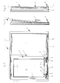
- 1 is a building window with a stock or frame 2, with one provided in the frame 2, the fixed-field glazing 3 having Fixed field and with a wing 4.
- the essentially from the sash 5 with the glazing 6 existing wing 4 is by means of a Parallelschiebekipp fitting provided on the frame 2 such that the wing 4 from its in the figure 1 shown closed position in which he the side of the fixed field in the frame closed window opening, by moving perpendicular to the window and Wing level (Ausstell Gay) in a Ausstelllage ( Figure 3) and then by Moving parallel to the window plane in an open position is movable in the the wing 5 seen from the inside of the building before the fixed-field glazing 3 is located.
- the wing 4 for example, for ventilation of his tilted closed position, as shown in Figure 2.
- the operated via a handle 7 Parallelschiebekipp fitting includes u.a. a Carriage assembly, which is in the area of the bottom of the lower horizontal spar 5.1 of the sash 5 is provided and essentially two of each other spaced carriage 8 is.
- Each carriage 8 has a carriage element 9, which with carriage rollers in a lower, horizontal running or Guide rail 10 at the lower, horizontal portion 2.1 of the frame 2 out and hinged to one end of a lower extension arm 11.
- the other end of each Ausstellarms 11 is pivotally connected to a bearing element 12, with which the relevant carriage 8 is attached to the spar 5.1.
- the two Carriage elements 9 are connected to each other via a lower coupling rod 13, so that the two extension arms 11, the coupling rod 13, the bearing elements 12 and the Joints at the ends of the extension arms 11 form a lower articulated parallelogram. This is always one at the wing movement perpendicular to the window plane Parallel position of the lower portion of the wing 5 with the plane of the frame guaranteed.
- each bearing element 14 is under Use of suitable fasteners, e.g.
- the in a plane vertical or about oriented perpendicular to the plane of the wing 4 plate-shaped portion 14.1 is available a partial section over the plane of the inner surface of the sash frame 5.
- hinge pin 15 on each bearing element 14 has an end an upper Ausstellarms 16 hinged.
- each Ausstellarms 16 is provided with a pivot pin 17, which in fully assembled Parallelschiebekipp fitting in a warehouse or Joint opening 18 of a slider 19 engages and there about the longitudinal axis of the Toggle pin 17 rotatable and also within certain limits about axes radially this longitudinal axis is tiltable.
- Et al to simplify the assembly of the wing 4 am Frame 2 and / or for removing this wing for repair purposes is the Pivot pin 17 releasably held in the hinge opening 18, in the illustrated embodiment in that the pivot pin 17 at its in the Hinge 18 in reaching end has an annular groove 17.1, which in in the Joint opening 18 locked pivot pin 17 of a slider 19 in the 19th provided and actuated by an eccentric 20 locking slide 21st is engaged behind, as indicated in the figure 7 with broken lines is.
- the locking slide 21 has a keyhole-shaped opening 21.1, the region of greater width to the outer diameter of the pivot pin 17 and whose area of smaller width to the diameter of the pivot pin 17 in the region of Ring groove 17.1 corresponds.
- the designed as a narrow cuboid slider 19 is shown in the Embodiment formed in two parts, namely consisting of the in Figures 5 and 7 lower, elongated and approximately cuboidal on the outer contour Slide part 19.1, in which also the joint opening 18, the eccentric 20 and the Locking slide 21 are provided, and from the in the figures 5 and 7 upper slide part 19.2, which is designed like a strip and mounted on the slider 19 with molded, preferably also designed as notches projections or Pin 22 engages in openings 23 of the slide part 19.1.
- the openings 23 are each pair provided at the two ends of the slide part 19.1 and serve et al also to order at the bottom of the slide part 19.1 at the two ends of this Gleiterteils each two spring-like, rounded tongues 24 to form, in the hereinafter described in more detail a resilient investment or leadership for forms the respective slider 19 on the two slider longitudinal sides.
- the slide part 19.2 After attachment of the slide part 19.2 at the top of the slide part 19.1 et al also the locking slide 21 and for the most part also the eccentric 20th receiving interior of the slider part 19.1 closed.
- the slide part 19.2 is located then with one end adjacent one end of the slider part 19.1. With the the other end is the slide part 19.2 on the relevant end of the slider part 19.1 before and is there provided with a molded, block-like connector 25, which is at mounted slide part 19.2 before the respective end or before the relevant end face of the slider part 19.1 is located.
- the connector 25 is shaped so that it is completely assembled Slider 19 at least on the two longitudinal sides of this slider with respect to the Outer contour, the continuation or approximately the continuation of the slide part 19.1 forms.
- a bore 26 is provided which is parallel with its axis arranged to the longitudinal axis of the slider 19 and in the illustrated embodiment both on the slide part 19.1 side facing, as well as on this Slider part facing away from the attachment piece 25 is open.
- the attachment piece 25 is further extending into the bore 26 Clamping screw 27 is provided.
- the two sliders 19 are in a common horizontal guide rail 28 in Slidably received longitudinally of this rail.
- the guide rail 28 is attached to the upper, horizontal part or spar 2.2 of the frame 2 resting, namely at the building interior facing surface.
- the guide rail is formed by a C-profile, which on his underside of the building window 1 facing bottom is open.
- the two sliders 19 are each received in this guide rail so that the bottom of the slide part 19.1 at the lower open side of the Guide rail 28 is located and the four tongues 24 in each case to the Slot-shaped opening of the guide rail 28 bounding edges 28.1 this Rail resiliently abut, which u.a. a noise-free sliding of the slider 19 in the Guide rail 28 is ensured.
- the two sliders 19 are still in the Guide rail 28 arranged that they including their attachment pieces 25th completely received in the guide rail 28 and their with the Attachment pieces 25 facing ends facing each other.
- the connecting rod 29 is completely received in the guide rail 28. Between the two ends of the connecting rod 29 is located on the Connecting rod 29 is an additional, also in the guide rail 28th Guided guide piece 30, which in particular a rattling by hitting the Connecting rod 29 prevents the guide rail 28.
- the Ausstellarme 16, the via the connecting rod 29 interconnected slider 19, the Bearing elements 14 and the joints at the two ends of the extension arms 16 form an upper joint parallelogram, which in the upper region of the wing 4 at Tilting and moving this wing perpendicular to the window plane one each clear positioning or a clear parallel position of the wing 4 to Ensures window level.
- the two upper extension arms 16 With their Longitudinal extent parallel or approximately parallel to the longitudinal axis of the guide rail 28th oriented and are located directly below this guide rail. at tilted or flared window are the two extension arms 16 with their Longitudinal extension respectively oriented obliquely to the longitudinal axis of the guide rail 28, i. the extension arms 16 close with the longitudinal axis of the guide rail 28 a Angle less than 90 °.
- the effective Length of the extension arms 16, i. the distance between the two joints at each Ausstellarm 16 equal to the effective length of the Ausstellarme 11, i. like that Distance between the two joints on each extension arm 11.
- the guide rail 28 is, for example, of a length of a metal profile, e.g. formed of an aluminum profile.
- the sliders 19 and their parts 19.1 and 19.2 consisting of a lubricious material, for example of a lubricious Plastic, but with the exception of the eccentric 20 and locking slide 21, the are made of metal.
- the additional guide piece 30 is made of a slidable material, for example made of plastic and, for example, by Clamping attached to the connecting rods 29.
- the two-part slider 19 fills the entire cross section of the guide rail 28, so that the slide part 19.1 at the opening edge 28.1 of the guide rail and the Slide part 19.2 at the bottom 28.2 of the guide rail 28 and thereby support a undesirable separation of the over the pins 22 and openings 23 with each other connected parts 19.1 and 19.2 is prevented.
- the remaining elements of the parallel slide-tilt fitting are made of metal, For example, made of steel, namely the two upper Ausstellarme 16 and the associated bearing elements 14 of a metal sheet, such as steel.
- the Connecting or coupling rod 29 By receiving the connecting rod 29 in the guide rail 28 is the Connecting or coupling rod 29 visually not disturbing visible. An additional long cover for the connecting rod 29 is not required. This results not only a visually appealing for the building window Appearance in which as little as possible of the Parallelschiebekipp fitting see, but also an overall very reasonably priced solution in particular by Material savings. But to improve the visual appearance it is possible, the bearing elements 14 by cover elements or caps, not shown from a suitable material, such as plastic cover.
- the two-part design of the slider 19 has the advantage that such fittings, the have only the slider part 19.1 corresponding slider, using the Slide parts 19.2 and the coupling rod 29 are rebuilt in the context of the invention can.
Landscapes
- Engineering & Computer Science (AREA)
- Mechanical Engineering (AREA)
- Wing Frames And Configurations (AREA)
- Window Of Vehicle (AREA)
- Support Devices For Sliding Doors (AREA)
- Door And Window Frames Mounted To Openings (AREA)
Abstract
Description
- Fig. 1
- das Gebäudefenster in Draufsicht und von der Gebäudeinnenseite her gesehen;
- Fig. 2 und 3
- das Gebäudefenster der Figur 1 in Seitenansicht, und zwar im gekippten Zustand (Figur 2) sowie in einer Verschiebeposition (Fig. 3);
- Fig. 4
- in perspektivischer Teildarstellung das Gebäudefenster im gekippten Zustand, und zwar im oberen Bereich des Stock-oder Blendrahmens sowie des Flügelrahmens;
- Fig. 5
- in perspektivischer Explosionsdarstellung die beiden Teile eines zweiteiligen, als Gleiter ausgeführten Führungselementes der oberen Führung des Parallelschiebekipp-Beschlages des Gebäudefensters der Figuren 1 - 4;
- Fig. 6 und 7
- den Gleiter der Figur 5 im zusammengebauten Zustand in einer Unteransicht sowie in Seitenansicht;
- Fig. 8
- einen Schnitt durch eine die obere Führung bildende Führungsschiene mit einem Gleiter und mit der oberen Koppelstange.
- 1
- Gebäudefenster
- 2
- Blendrahmen
- 2.1
- unterer, horizontaler Bereich des Blendrahmens
- 2.2
- oberer, horizontaler Abschnitt des Blendrahmens
- 3
- Festfeldverglasung
- 4
- Parallelschiebekipp-Flügel
- 5
- Flügelrahmen
- 5.1
- unterer, horizontaler Holm des Flügelrahmens
- 5.2
- oberer, horizontaler Holm des Flügelrahmens
- 6
- Verglasung
- 7
- Hebel
- 8
- Laufwagen
- 9
- Laufwagenelement
- 10
- untere, horizontale Führungs- oder Laufschiene
- 11
- unterer Ausstellarm
- 12
- Lagerelement
- 13
- untere, horizontale Koppelstange
- 14
- Lagerelement
- 14.1
- plattenförmiger Abschnitt des Lagerelementes 14
- 14.2
- Schenkel des Lagerelementes 14
- 15
- Gelenk
- 16
- oberer Ausstellarm
- 17
- Gelenkzapfen
- 17.1
- Ringnut
- 18
- Gelenköffnung
- 19
- Gleiter
- 19.1, 19.2
- Teil des Gleiters 19
- 20
- Exzenter
- 21
- Verriegelungsschieber
- 21.1
- Schlüssellochöffnung im Verriegelungsschieber
- 22
- Vorsprung
- 23
- Öffnung
- 24
- federnde Zunge
- 25
- Befestigungsabschnitt
- 26
- Bohrung
- 27
- Klemmschraube
- 28
- obere Führungsschiene
- 28.1
- Rand der Führungsschiene
- 28.2
- Boden der Führungsschiene
- 29
- obere, horizontale Koppelstange
- 30
- zusätzliches Führungsstück
Claims (12)
- Beschlag für eine Ausstell- und Kippbewegung eines Flügels eines Gebäudefensters oder einer Gebäudetür, insbesondere eines Parallelschiebekipp-Fensters oder einer Parallelschiebekipp-Tür, mit wenigstens zwei im Bereich der Oberseite eines Flügelrahmens (5) mit jeweils einem Ende anlenkbaren ersten Austellarmen (16), die mit ihrem anderen Ende jeweils an einem Führungselement (19) angelenkt sind, welches in einer an einem Blendrahmen (2) des Fensters oder der Tür befestigbaren ersten Führung (28) verschiebbar angeordnet ist, dadurch gekennzeichnet, dass die beiden Führungselemente (19) durch ein in der ersten Führung (28) aufgenommenes Koppelglied (29) miteinander verbunden sind, sodass bei montiertem Beschlag die Gelenke der ersten Ausstellarme (16) die Eckpunkte eines Gelenkvierecks oder Gelenkparallelogramm bilden.
- Beschlag nach Anspruch 1, dadurch gekennzeichnet, dass das Koppelelement eine in der ersten Führung (28) aufgenommene Koppeloder Verbindungsstange (29) ist,
und/oder
dass die ersten Führungselemente Gleiter oder Gleitstücke (19) sind, die in der ersten Führung (28) formschlüssig aber in Längsrichtung dieser Führung gleitend aufgenommen sind. - Beschlag nach Anspruch 1 oder 2, dadurch gekennzeichnet, dass die erste Führung (28) an der einer Gebäudeinnenseite zugewandten Seite des Blendrahmens (2) aufliegend befestigbar ist;
und/oder
dass die erste Führung eine Führungsschiene (28), beispielsweise eine im Querschnitt als C-Profil ausgebildete Führungsschiene (28) ist. - Beschlag nach einem der vorhergehenden Ansprüche, dass das jeweilige erste Führungselement (19) aus einem gleitfähigen Material, beispielsweise aus einem Kunststoff gefertigt ist.
- Beschlag nach einem der vorhergehenden Ansprüche, dadurch gekennzeichnet, dass die Gelenkverbindung zwischen dem jeweiligen ersten Ausstellarm (16) und dem zugehörigen Führungselement (19) lösbar ausgebildet ist,
wobei beispielsweise für die lösbare Verbindung zwischen dem ersten Ausstellarm (16) und dem zugehörigen Führungselement (19) im Führungselement ein Lager (18) mit einer manuell betätigbaren Verriegelungseinrichtung (20, 21, 21 ') für einen Gelenkzapfen (17) am ersten Ausstellarm (16) vorgesehen ist. - Beschlag nach einem der vorhergehenden Ansprüche, dadurch gekennzeichnet, dass die Führungselemente (19) jeweils zweiteilig ausgebildet sind, und dass an einem ersten Teil (19.2) jedes Führungselementes (19) das erste Koppelelement (29) befestigt oder befestigbar ist,
wobei beispielsweise am ersten Teil jedes Führungselementes (19) Mittel (25, 26, 27) zum lösbaren Befestigen des ersten Koppelelementes (29) vorgesehen sind und diese Mittel zum Befestigen z.B. von einer Bohrung (26) mit Klemmmitteln, beispielsweise mit einer Klemmschraube (27) gebildet sind. - Beschlag nach einem der vorhergehenden Ansprüche, dadurch gekennzeichnet, dass im zweiten Teil (19.1) des Führungselementes (19) bzw. in einer in diesem Teil gebildeten Ausnehmung die Verriegelungseinrichtung (20, 21, 21 ') für den Gelenkzapfen (17) am ersten Austellarm (16) vorgesehen sind.
- Beschlag nach einem der vorhergehenden Ansprüche, gekennzeichnet durch Mittel (22, 23) über die die beiden Teile (19.1, 19.2) des zweiteiligen Führungselementes (19) durch Fügen in einer Achsrichtung senkrecht zur Längsachse der ersten Führung (28) formschlüssig miteinander verbunden sind, und dass jedes Führungselement (19) durch die erste Führung (28) derart formschlüssig aufgenommen ist, dass durch diese ein Lösen der Fügeverbindung zwischen den beiden Teilen (19.1, 19.2) des zweiteiligen Führungselementes (19) verhindert ist,
wobei beispielsweise die Mittel von Vorsprüngen und/oder Zapfen (22) sowie von diese Vorsprünge und/oder Zapfen (22) aufnehmenden Ausnehmungen und/oder Öffnungen (23) an den Teilen (19.1, 19.2) gebildet sind. - Beschlag nach einem der vorhergehenden Ansprüche, dadurch gekennzeichnet, dass das jeweilige Führungselement (19) federnde Anlageflächen aufweist, die vorzugsweise durch angeformte Abschnitte oder Zungen (24) gebildet sind.
- Beschlag nach einem der vorhergehenden Ansprüche, dadurch gekennzeichnet, dass er Bestandteil eines Parallelschiebekipp-Beschlages ist, der auch eine an einer Unterseite des Flügels (4) oder des Flügelrahmens (5) zu montierende Laufwagenanordnung mit wenigstens zwei in einer zweiten, unteren Führung (10) geführten und jeweils an einem Ende eines zweiten unteren Aufstellarmes (11) angelenkten Laufwagen (8) aufweist, welche über ein zweites, unteres Koppelelement (13) miteinander verbunden sind,
wobei beispielsweise die wirksame Länge der oberen, ersten Ausstellarme (16) gleich der wirksamen Länge der zweiten, unteren Ausstellarme (11) ist. - Beschlag nach einem der vorhergehenden Ansprüche, dadurch gekennzeichnet, dass am ersten Koppelelement (29) zwischen den beiden Führungselementen (19) ein zusätzliches, in der ersten Führung (28) geführtes Führungselement (30) vorgesehen ist,
wobei beispielsweise das zusätzliche Führungselement (30) ein Gleitstück oder Gleitkörper aus einem gleitfähigen Material, beispielsweise aus Kunststoff ist. - Parallelschiebekipp-Fenster oder Parallelschiebekipp-Tür mit wenigstens einem in
einem Stock- oder Blendrahmen (2) angeordneten Flügel (4) und mit einem zwischen dem Flügel (4) oder dessen Flügelrahmen (5) und dem Blendrahmen (2) vorgesehenen Parallelschiebekipp-Beschlag, dadurch gekennzeichnet, dass der Beschlag nach einem der vorhergehenden Ansprüche ausgebildet ist.
Applications Claiming Priority (2)
| Application Number | Priority Date | Filing Date | Title |
|---|---|---|---|
| DE202004000610U DE202004000610U1 (de) | 2004-01-15 | 2004-01-15 | Beschlag für eine Ausstell- und Kippbewegung eines Flügels eines Gebäudefensters oder einer Gebäudetür sowie Parallelschiebekipp-Fenster oder -Tür mit einem solchen Beschlag |
| DE202004000610U | 2004-01-15 |
Publications (2)
| Publication Number | Publication Date |
|---|---|
| EP1555368A1 true EP1555368A1 (de) | 2005-07-20 |
| EP1555368B1 EP1555368B1 (de) | 2006-12-27 |
Family
ID=32240765
Family Applications (1)
| Application Number | Title | Priority Date | Filing Date |
|---|---|---|---|
| EP04014217A Revoked EP1555368B1 (de) | 2004-01-15 | 2004-06-17 | Beschlag für eine Ausstell- und Kippbewegung eines Flügels eines Gebäudefensters oder einer Gebäudetür sowie Parallelschiebekipp-Fenster oder -Tür mit einem solchen Beschlag |
Country Status (3)
| Country | Link |
|---|---|
| EP (1) | EP1555368B1 (de) |
| AT (1) | ATE349593T1 (de) |
| DE (2) | DE202004000610U1 (de) |
Cited By (3)
| Publication number | Priority date | Publication date | Assignee | Title |
|---|---|---|---|---|
| DE102011053809A1 (de) | 2011-09-20 | 2013-03-21 | Hautau Gmbh | Leicht zugänglicher Beschlag zur Einstellung der Sperrkraft |
| CN103827429A (zh) * | 2011-07-14 | 2014-05-28 | 森弗雷克斯铝系统有限责任公司 | 滑动和转动翼扇系统 |
| EP1959080B1 (de) | 2007-02-15 | 2017-12-27 | HAUTAU GmbH | Beschlag für einen Schiebeflügel von Fenster oder Tür |
Families Citing this family (4)
| Publication number | Priority date | Publication date | Assignee | Title |
|---|---|---|---|---|
| PL1876319T3 (pl) * | 2006-07-06 | 2015-04-30 | Hautau Gmbh | Prowadnica ślizgowa dla skrzydeł przesuwnych albo skrzydeł przesuwnych z równoległym odstawieniem |
| DE102007021980B4 (de) † | 2007-05-10 | 2013-03-14 | Hautau Gmbh | Gleitelement für Schiebetürführung |
| DE102007022398B3 (de) | 2007-05-10 | 2008-09-11 | Hautau Gmbh | Ohne Werkzeug montierfähiges Gleiterbauteil |
| DE202008004292U1 (de) | 2008-03-27 | 2009-08-06 | Siegenia-Aubi Kg | Beschlag für eine Ausstell- und Kippbewegung eines Flügels eines Gebäudefensters oder einer Gebäudetür |
Citations (4)
| Publication number | Priority date | Publication date | Assignee | Title |
|---|---|---|---|---|
| EP0231498A2 (de) * | 1986-02-06 | 1987-08-12 | Gretsch Unitas GmbH Baubeschläge | Beschlag für einen wenigstens kippbaren Flügel eines Fensters, einer Tür od. dgl. |
| EP0980951A2 (de) * | 1998-08-17 | 2000-02-23 | Wilhelm Weidtmann GmbH & Co. KG | Abstell-Schiebebeschlag für Fenster, Türen od. dgl. |
| EP1170448A1 (de) * | 2000-07-04 | 2002-01-09 | Gretsch-Unitas GmbH Baubeschläge | Laufwagen für einen Parallelschiebe- und Kippbeschlag eines Gebäudefensters oder einer Gebäudefenstertür sowie Gebäudefenster bzw. Gebäudefenstertür mit einem solchen Parallelschiebe-Kippbeschlag |
| EP1178174A2 (de) * | 2000-08-01 | 2002-02-06 | Wilhelm Weidtmann GmbH & Co. KG | Schiebebeschlag für Fenster, Türen od. dgl. |
-
2004
- 2004-01-15 DE DE202004000610U patent/DE202004000610U1/de not_active Expired - Lifetime
- 2004-06-17 AT AT04014217T patent/ATE349593T1/de not_active IP Right Cessation
- 2004-06-17 EP EP04014217A patent/EP1555368B1/de not_active Revoked
- 2004-06-17 DE DE502004002437T patent/DE502004002437D1/de not_active Expired - Fee Related
Patent Citations (4)
| Publication number | Priority date | Publication date | Assignee | Title |
|---|---|---|---|---|
| EP0231498A2 (de) * | 1986-02-06 | 1987-08-12 | Gretsch Unitas GmbH Baubeschläge | Beschlag für einen wenigstens kippbaren Flügel eines Fensters, einer Tür od. dgl. |
| EP0980951A2 (de) * | 1998-08-17 | 2000-02-23 | Wilhelm Weidtmann GmbH & Co. KG | Abstell-Schiebebeschlag für Fenster, Türen od. dgl. |
| EP1170448A1 (de) * | 2000-07-04 | 2002-01-09 | Gretsch-Unitas GmbH Baubeschläge | Laufwagen für einen Parallelschiebe- und Kippbeschlag eines Gebäudefensters oder einer Gebäudefenstertür sowie Gebäudefenster bzw. Gebäudefenstertür mit einem solchen Parallelschiebe-Kippbeschlag |
| EP1178174A2 (de) * | 2000-08-01 | 2002-02-06 | Wilhelm Weidtmann GmbH & Co. KG | Schiebebeschlag für Fenster, Türen od. dgl. |
Cited By (5)
| Publication number | Priority date | Publication date | Assignee | Title |
|---|---|---|---|---|
| EP1959080B1 (de) | 2007-02-15 | 2017-12-27 | HAUTAU GmbH | Beschlag für einen Schiebeflügel von Fenster oder Tür |
| EP3216958B1 (de) | 2007-02-15 | 2018-05-02 | HAUTAU GmbH | Beschlag für einen schiebeflügel |
| CN103827429A (zh) * | 2011-07-14 | 2014-05-28 | 森弗雷克斯铝系统有限责任公司 | 滑动和转动翼扇系统 |
| DE102011053809A1 (de) | 2011-09-20 | 2013-03-21 | Hautau Gmbh | Leicht zugänglicher Beschlag zur Einstellung der Sperrkraft |
| EP2573304A2 (de) | 2011-09-20 | 2013-03-27 | HAUTAU GmbH | Beschlag zur leichten Einstellung einer Sperrkraft |
Also Published As
| Publication number | Publication date |
|---|---|
| DE202004000610U1 (de) | 2004-04-29 |
| ATE349593T1 (de) | 2007-01-15 |
| EP1555368B1 (de) | 2006-12-27 |
| DE502004002437D1 (de) | 2007-02-08 |
Similar Documents
| Publication | Publication Date | Title |
|---|---|---|
| DE10329518B4 (de) | Führungseinrichtung für eine Schiebetür | |
| DE2706013A1 (de) | Treibstangenbeschlag fuer aus metall- oder kunststoffprofilen zusammengesetzte fenster, tueren o.dgl. | |
| EP1152112A2 (de) | Verstellbare Scharnier-Rahmen-Anordnung | |
| CH670555A5 (de) | ||
| DE20108229U1 (de) | Führungseinrichtung für eine Faltschiebetür | |
| DE8010921U1 (de) | Scharnierbandverbindung fuer fenster, tueren und tore | |
| EP2105564A2 (de) | Beschlag für eine Ausstell- und Kippbewegung eines Flügels eines Gebäudefensters oder einer Gebäudetür | |
| EP1555368B1 (de) | Beschlag für eine Ausstell- und Kippbewegung eines Flügels eines Gebäudefensters oder einer Gebäudetür sowie Parallelschiebekipp-Fenster oder -Tür mit einem solchen Beschlag | |
| DE3033751C2 (de) | Beschlag für den Schiebeflügel von Fenstern, Türen oder dgl. aus Holz- oder Kunststoffprofilen | |
| DE3900455C2 (de) | Dachkoffer für Kraftfahrzeuge | |
| EP0531626B1 (de) | Beschlag für insb. zwangsweise kipp- und parallel abstellbare Flügel | |
| EP0487825B1 (de) | Verdeckt angeordneter Beschlag für Drehflügel, insb. für Dreh-Kipp-Flügel von Fenstern oder Türen | |
| EP1298271A2 (de) | Laufwagenanordnung für einen Beschlag für Hebe-Schiebe-Türen oder -Fenster sowie Beschlag mit einer solchen Laufwagenanordnung | |
| EP3480407A1 (de) | Vertikalschiebeelement | |
| EP1605125A2 (de) | Führungssystem zum Führen von Schiebetüren oder Schiebefenstern | |
| EP1243212B1 (de) | Duschtrennwand | |
| EP1234942B1 (de) | Beschlag für ein Fenster, eine Tür oder dergl. | |
| EP1813751A1 (de) | Verdeckt liegendes Band | |
| DE202007009636U1 (de) | Flügelanordnung | |
| DE19801280A1 (de) | Führungs- und Laufschienenanordnung eines Schwingtors, Decken- oder Seiten-Sektionaltors oder Rundlauftors | |
| DE3722094C2 (de) | Leicht montierbarer Beschlag mit Sicherheit gegen Einsteigen | |
| DE8201403U1 (de) | Eckumlenkung für Treibstangenbeschläge von Fenstern, Türen od. dgl. | |
| DE69804669T2 (de) | Balkonverglasung | |
| CH655762A5 (en) | Folding sliding part for external and internal walls of buildings | |
| DE3939127A1 (de) | Verdeckt im falz angeordneter beschlag fuer kipp-schwenkfluegelfenster oder -tueren, insb. mit holzrahmen |
Legal Events
| Date | Code | Title | Description |
|---|---|---|---|
| PUAI | Public reference made under article 153(3) epc to a published international application that has entered the european phase |
Free format text: ORIGINAL CODE: 0009012 |
|
| AK | Designated contracting states |
Kind code of ref document: A1 Designated state(s): AT BE BG CH CY CZ DE DK EE ES FI FR GB GR HU IE IT LI LU MC NL PL PT RO SE SI SK TR |
|
| AX | Request for extension of the european patent |
Extension state: AL HR LT LV MK |
|
| 17P | Request for examination filed |
Effective date: 20050923 |
|
| GRAP | Despatch of communication of intention to grant a patent |
Free format text: ORIGINAL CODE: EPIDOSNIGR1 |
|
| AKX | Designation fees paid |
Designated state(s): AT DE IT TR |
|
| GRAS | Grant fee paid |
Free format text: ORIGINAL CODE: EPIDOSNIGR3 |
|
| GRAA | (expected) grant |
Free format text: ORIGINAL CODE: 0009210 |
|
| AK | Designated contracting states |
Kind code of ref document: B1 Designated state(s): AT DE IT TR |
|
| REF | Corresponds to: |
Ref document number: 502004002437 Country of ref document: DE Date of ref document: 20070208 Kind code of ref document: P |
|
| PLBI | Opposition filed |
Free format text: ORIGINAL CODE: 0009260 |
|
| PLAX | Notice of opposition and request to file observation + time limit sent |
Free format text: ORIGINAL CODE: EPIDOSNOBS2 |
|
| 26 | Opposition filed |
Opponent name: HAUTAU GMBH Effective date: 20070927 |
|
| PLAF | Information modified related to communication of a notice of opposition and request to file observations + time limit |
Free format text: ORIGINAL CODE: EPIDOSCOBS2 |
|
| PLBB | Reply of patent proprietor to notice(s) of opposition received |
Free format text: ORIGINAL CODE: EPIDOSNOBS3 |
|
| PGFP | Annual fee paid to national office [announced via postgrant information from national office to epo] |
Ref country code: AT Payment date: 20090615 Year of fee payment: 6 Ref country code: IT Payment date: 20090620 Year of fee payment: 6 Ref country code: TR Payment date: 20090528 Year of fee payment: 6 |
|
| PGFP | Annual fee paid to national office [announced via postgrant information from national office to epo] |
Ref country code: DE Payment date: 20090622 Year of fee payment: 6 |
|
| PG25 | Lapsed in a contracting state [announced via postgrant information from national office to epo] |
Ref country code: IT Free format text: LAPSE BECAUSE OF NON-PAYMENT OF DUE FEES Effective date: 20100617 |
|
| PG25 | Lapsed in a contracting state [announced via postgrant information from national office to epo] |
Ref country code: DE Free format text: LAPSE BECAUSE OF NON-PAYMENT OF DUE FEES Effective date: 20110101 |
|
| PG25 | Lapsed in a contracting state [announced via postgrant information from national office to epo] |
Ref country code: AT Free format text: LAPSE BECAUSE OF NON-PAYMENT OF DUE FEES Effective date: 20100617 |
|
| RDAF | Communication despatched that patent is revoked |
Free format text: ORIGINAL CODE: EPIDOSNREV1 |
|
| RDAG | Patent revoked |
Free format text: ORIGINAL CODE: 0009271 |
|
| STAA | Information on the status of an ep patent application or granted ep patent |
Free format text: STATUS: PATENT REVOKED |
|
| 27W | Patent revoked |
Effective date: 20110708 |