EP1554184B1 - Zusammenklappbares gestell - Google Patents
Zusammenklappbares gestell Download PDFInfo
- Publication number
- EP1554184B1 EP1554184B1 EP03808741A EP03808741A EP1554184B1 EP 1554184 B1 EP1554184 B1 EP 1554184B1 EP 03808741 A EP03808741 A EP 03808741A EP 03808741 A EP03808741 A EP 03808741A EP 1554184 B1 EP1554184 B1 EP 1554184B1
- Authority
- EP
- European Patent Office
- Prior art keywords
- lateral frame
- frame members
- another
- corner posts
- base member
- Prior art date
- Legal status (The legal status is an assumption and is not a legal conclusion. Google has not performed a legal analysis and makes no representation as to the accuracy of the status listed.)
- Expired - Lifetime
Links
- 238000010276 construction Methods 0.000 claims description 2
- 238000006073 displacement reaction Methods 0.000 description 2
- 238000002955 isolation Methods 0.000 description 2
- 238000004519 manufacturing process Methods 0.000 description 2
- 238000013459 approach Methods 0.000 description 1
- 238000010586 diagram Methods 0.000 description 1
- 230000013011 mating Effects 0.000 description 1
- 238000000034 method Methods 0.000 description 1
- 230000000717 retained effect Effects 0.000 description 1
Images


Classifications
-
- B—PERFORMING OPERATIONS; TRANSPORTING
- B65—CONVEYING; PACKING; STORING; HANDLING THIN OR FILAMENTARY MATERIAL
- B65D—CONTAINERS FOR STORAGE OR TRANSPORT OF ARTICLES OR MATERIALS, e.g. BAGS, BARRELS, BOTTLES, BOXES, CANS, CARTONS, CRATES, DRUMS, JARS, TANKS, HOPPERS, FORWARDING CONTAINERS; ACCESSORIES, CLOSURES, OR FITTINGS THEREFOR; PACKAGING ELEMENTS; PACKAGES
- B65D19/00—Pallets or like platforms, with or without side walls, for supporting loads to be lifted or lowered
- B65D19/02—Rigid pallets with side walls, e.g. box pallets
- B65D19/06—Rigid pallets with side walls, e.g. box pallets with bodies formed by uniting or interconnecting two or more components
- B65D19/08—Rigid pallets with side walls, e.g. box pallets with bodies formed by uniting or interconnecting two or more components made wholly or mainly of metal
- B65D19/12—Collapsible pallets
-
- B—PERFORMING OPERATIONS; TRANSPORTING
- B65—CONVEYING; PACKING; STORING; HANDLING THIN OR FILAMENTARY MATERIAL
- B65D—CONTAINERS FOR STORAGE OR TRANSPORT OF ARTICLES OR MATERIALS, e.g. BAGS, BARRELS, BOTTLES, BOXES, CANS, CARTONS, CRATES, DRUMS, JARS, TANKS, HOPPERS, FORWARDING CONTAINERS; ACCESSORIES, CLOSURES, OR FITTINGS THEREFOR; PACKAGING ELEMENTS; PACKAGES
- B65D19/00—Pallets or like platforms, with or without side walls, for supporting loads to be lifted or lowered
- B65D19/38—Details or accessories
- B65D19/44—Elements or devices for locating articles on platforms
-
- B—PERFORMING OPERATIONS; TRANSPORTING
- B65—CONVEYING; PACKING; STORING; HANDLING THIN OR FILAMENTARY MATERIAL
- B65D—CONTAINERS FOR STORAGE OR TRANSPORT OF ARTICLES OR MATERIALS, e.g. BAGS, BARRELS, BOTTLES, BOXES, CANS, CARTONS, CRATES, DRUMS, JARS, TANKS, HOPPERS, FORWARDING CONTAINERS; ACCESSORIES, CLOSURES, OR FITTINGS THEREFOR; PACKAGING ELEMENTS; PACKAGES
- B65D2519/00—Pallets or like platforms, with or without side walls, for supporting loads to be lifted or lowered
- B65D2519/00004—Details relating to pallets
- B65D2519/00009—Materials
- B65D2519/00154—Materials for the side walls
- B65D2519/00164—Metal
-
- B—PERFORMING OPERATIONS; TRANSPORTING
- B65—CONVEYING; PACKING; STORING; HANDLING THIN OR FILAMENTARY MATERIAL
- B65D—CONTAINERS FOR STORAGE OR TRANSPORT OF ARTICLES OR MATERIALS, e.g. BAGS, BARRELS, BOTTLES, BOXES, CANS, CARTONS, CRATES, DRUMS, JARS, TANKS, HOPPERS, FORWARDING CONTAINERS; ACCESSORIES, CLOSURES, OR FITTINGS THEREFOR; PACKAGING ELEMENTS; PACKAGES
- B65D2519/00—Pallets or like platforms, with or without side walls, for supporting loads to be lifted or lowered
- B65D2519/00004—Details relating to pallets
- B65D2519/00258—Overall construction
- B65D2519/00313—Overall construction of the base surface
- B65D2519/00328—Overall construction of the base surface shape of the contact surface of the base
- B65D2519/00333—Overall construction of the base surface shape of the contact surface of the base contact surface having a stringer-like shape
-
- B—PERFORMING OPERATIONS; TRANSPORTING
- B65—CONVEYING; PACKING; STORING; HANDLING THIN OR FILAMENTARY MATERIAL
- B65D—CONTAINERS FOR STORAGE OR TRANSPORT OF ARTICLES OR MATERIALS, e.g. BAGS, BARRELS, BOTTLES, BOXES, CANS, CARTONS, CRATES, DRUMS, JARS, TANKS, HOPPERS, FORWARDING CONTAINERS; ACCESSORIES, CLOSURES, OR FITTINGS THEREFOR; PACKAGING ELEMENTS; PACKAGES
- B65D2519/00—Pallets or like platforms, with or without side walls, for supporting loads to be lifted or lowered
- B65D2519/00004—Details relating to pallets
- B65D2519/00258—Overall construction
- B65D2519/00492—Overall construction of the side walls
- B65D2519/00512—Overall construction of the side walls skeleton type
-
- B—PERFORMING OPERATIONS; TRANSPORTING
- B65—CONVEYING; PACKING; STORING; HANDLING THIN OR FILAMENTARY MATERIAL
- B65D—CONTAINERS FOR STORAGE OR TRANSPORT OF ARTICLES OR MATERIALS, e.g. BAGS, BARRELS, BOTTLES, BOXES, CANS, CARTONS, CRATES, DRUMS, JARS, TANKS, HOPPERS, FORWARDING CONTAINERS; ACCESSORIES, CLOSURES, OR FITTINGS THEREFOR; PACKAGING ELEMENTS; PACKAGES
- B65D2519/00—Pallets or like platforms, with or without side walls, for supporting loads to be lifted or lowered
- B65D2519/00004—Details relating to pallets
- B65D2519/00258—Overall construction
- B65D2519/00492—Overall construction of the side walls
- B65D2519/00532—Frame structures
-
- B—PERFORMING OPERATIONS; TRANSPORTING
- B65—CONVEYING; PACKING; STORING; HANDLING THIN OR FILAMENTARY MATERIAL
- B65D—CONTAINERS FOR STORAGE OR TRANSPORT OF ARTICLES OR MATERIALS, e.g. BAGS, BARRELS, BOTTLES, BOXES, CANS, CARTONS, CRATES, DRUMS, JARS, TANKS, HOPPERS, FORWARDING CONTAINERS; ACCESSORIES, CLOSURES, OR FITTINGS THEREFOR; PACKAGING ELEMENTS; PACKAGES
- B65D2519/00—Pallets or like platforms, with or without side walls, for supporting loads to be lifted or lowered
- B65D2519/00004—Details relating to pallets
- B65D2519/00547—Connections
- B65D2519/00577—Connections structures connecting side walls, including corner posts, to each other
- B65D2519/00582—Connections structures connecting side walls, including corner posts, to each other structures intended to be disassembled, i.e. collapsible or dismountable
- B65D2519/00611—Connections structures connecting side walls, including corner posts, to each other structures intended to be disassembled, i.e. collapsible or dismountable side walls maintained connected to each other by means of auxiliary locking elements, e.g. spring loaded locking pins
-
- B—PERFORMING OPERATIONS; TRANSPORTING
- B65—CONVEYING; PACKING; STORING; HANDLING THIN OR FILAMENTARY MATERIAL
- B65D—CONTAINERS FOR STORAGE OR TRANSPORT OF ARTICLES OR MATERIALS, e.g. BAGS, BARRELS, BOTTLES, BOXES, CANS, CARTONS, CRATES, DRUMS, JARS, TANKS, HOPPERS, FORWARDING CONTAINERS; ACCESSORIES, CLOSURES, OR FITTINGS THEREFOR; PACKAGING ELEMENTS; PACKAGES
- B65D2519/00—Pallets or like platforms, with or without side walls, for supporting loads to be lifted or lowered
- B65D2519/00004—Details relating to pallets
- B65D2519/00547—Connections
- B65D2519/00636—Connections structures connecting side walls to the pallet
- B65D2519/00641—Structures intended to be disassembled
- B65D2519/00646—Structures intended to be disassembled by means of hinges
- B65D2519/00656—Structures intended to be disassembled by means of hinges separately formed
-
- B—PERFORMING OPERATIONS; TRANSPORTING
- B65—CONVEYING; PACKING; STORING; HANDLING THIN OR FILAMENTARY MATERIAL
- B65D—CONTAINERS FOR STORAGE OR TRANSPORT OF ARTICLES OR MATERIALS, e.g. BAGS, BARRELS, BOTTLES, BOXES, CANS, CARTONS, CRATES, DRUMS, JARS, TANKS, HOPPERS, FORWARDING CONTAINERS; ACCESSORIES, CLOSURES, OR FITTINGS THEREFOR; PACKAGING ELEMENTS; PACKAGES
- B65D2519/00—Pallets or like platforms, with or without side walls, for supporting loads to be lifted or lowered
- B65D2519/00004—Details relating to pallets
- B65D2519/00736—Details
- B65D2519/0081—Elements or devices for locating articles
- B65D2519/0082—Elements or devices for locating articles in the side wall
-
- B—PERFORMING OPERATIONS; TRANSPORTING
- B65—CONVEYING; PACKING; STORING; HANDLING THIN OR FILAMENTARY MATERIAL
- B65D—CONTAINERS FOR STORAGE OR TRANSPORT OF ARTICLES OR MATERIALS, e.g. BAGS, BARRELS, BOTTLES, BOXES, CANS, CARTONS, CRATES, DRUMS, JARS, TANKS, HOPPERS, FORWARDING CONTAINERS; ACCESSORIES, CLOSURES, OR FITTINGS THEREFOR; PACKAGING ELEMENTS; PACKAGES
- B65D2519/00—Pallets or like platforms, with or without side walls, for supporting loads to be lifted or lowered
- B65D2519/00004—Details relating to pallets
- B65D2519/00736—Details
- B65D2519/00865—Collapsible, i.e. at least two constitutive elements remaining hingedly connected
- B65D2519/00875—Collapsible, i.e. at least two constitutive elements remaining hingedly connected collapsible side walls
- B65D2519/009—Collapsible, i.e. at least two constitutive elements remaining hingedly connected collapsible side walls whereby all side walls are hingedly connected to the base panel
Definitions
- the present invention relates to a collapsible frame for receiving and transporting accommodated in the frame pockets, which in turn are provided for receiving items to be transported or stored, with a bottom part and side frame parts, which articulates at its lower end with the Connected to the bottom part and relative to the bottom part from a position perpendicular to the bottom part in a position substantially parallel to the bottom part position by about 90 ° or more are pivotable.
- a corresponding frame is for example from the German Laid-Open Publication No. 41 38 507
- the known frame are each a rigid upper frame member and a rigid lower frame member provided so that on the upper rigid frame part, which is partially in the form of parallel rails, slidable rods can be suspended with these hanging flexible webs of material on these rails.
- the side panels are defined by four corner posts, which have a pivot point in the middle and which are each hingedly connected to the upper frame member and the lower frame member, so that the posts can be made to buckle in the middle and in this way the whole frame can be folded.
- the known frame is intended to be folded only in the empty state, that is, without the accommodated in the frame pockets.
- the known frame is relatively expensive to manufacture, since each individual post must have a total of three different hinge points, namely a hinge relative to the lower frame part, a hinge relative to the upper frame part and in addition a kink in the center of the post.
- the side parts preferably consist essentially of two parallel and interconnected corner posts, but each of the corner posts now has only two joints, namely a hinge point for connection to the bottom part and a hinge point in the upper region for the connection with the cross brace.
- the cross struts of the opposite side parts are pivoted toward each other and connected together in an overlapping connection area.
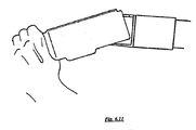
- the free ends of the transverse struts intermesh and are held together by a substantially engaging the engagement region pipe clamp substantially rigid.
- the pipe clamp is resiliently supported on one of the transverse struts and biased in the direction of the connecting region of the two transverse struts, so that when Auffactzuschwenken the two free ends of the crossbars initially interlock, the spring-biased clamp initially against the resilient Pre-tension is pushed back and then snaps back and overlaps the junction and so holds the two ends of the crossbars together.
- flexible material webs extend between the side parts, which extend horizontally between opposite side parts when erecting the side parts and are tensioned by the righting side plate.
- These flexible material webs in turn exert a tensile force on the side parts and pull the side parts toward each other, while the cross struts ensure a minimum distance of the side parts and thus the position of the side parts is clearly fixed.
- a plurality of webs are stretched in parallel between the side members and preferably also the transverse webs of material are interconnected by generally vertically or sloped connecting webs such that receiving pockets for articles are formed between the tensioned, horizontally extending webs and the interconnecting webs extending therebetween.
- the cross struts are preferably dimensioned so that in the unfolded state of the side parts the same extend substantially parallel to each other and perpendicular to the bottom part, wherein also the side parts defining corner posts with corresponding corner posts the bottom part are aligned, so that the unfolded frames are stackable.
- the articulation areas of the transverse struts on the side parts or their posts are preferably arranged so that the upper ends of the posts remain free and the upper ends of the corner posts of the side parts and the lower ends of the corner posts of the bottom parts are preferably designed so that they stack when stacked mesh several racks and are thus secured against lateral displacement.
- the upper ends of the corner posts of the bottom part are formed similar to the upper ends of the corner posts of the side parts and also the side parts and the corner posts of the side parts are hinged to the corner posts of the floor parts, that in the folded state of the frame, when the side panels are folded down, expose the top ends of the corner posts of the floor panels.
- the corner posts of the floor parts are generally relatively short post pieces, which extend substantially perpendicular to the plane otherwise defined by the bottom part. This configuration makes it possible that the collapsed racks are stackable.
- the hinged to the upper regions of the side parts or the corner posts of the side members cross struts in a position parallel to the side panels next to the side panels or next to the corner posts of the side parts and are lockable to these.
- the cross braces are pivoted into a position in which they extend more or less in extension of the side parts and the corner posts of the side parts.
- an articulation of the cross braces on the corner posts of the side parts in the manner appropriate in that one of the parts has an axis defining pivot pin and the other of the parts is received thereon with a slot, so that the cross member or the corresponding counterpart on the slot is displaceable on the pin and thereby certain positions of the transverse struts can be locked relative to the side parts.
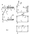
- FIG. 1 One recognizes in FIG. 1 in a side view of the bottom part 1, with short, laterally attached thereto corner posts 2, side parts 3, 4 and hinged to the side parts 3, 4 cross struts 5 and 6 respectively.
- FIG. 1 schematic side view in each case only the leading edges of the bottom part and the side parts are recognizable, which are preferably formed by generally consisting of square tubes cross struts or corner posts. It can be easily imagined that in a plane behind the plane of the paper again the same elements are connected twice and parallel to the elements of the plane of the paper by means of struts or the like, thus forming the frame as a whole.
- FIG. 1a the frame is completely folded.
- the cross member 5 is practically unfolded in extension to the side part 3 and covers the side parts 4, while the cross member 6 is folded back parallel to the side part 4 and preferably locked thereto.
- FIG. 1b is the left side part 3 erect.
- Figure 1c In addition, the right side panel is also erected, while the cross braces have still retained their original position relative to the side panels 3 and 4, as it consists in the folded state.
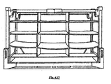
- FIGS. 2a-e show exactly the same sequence of folding a frame, in which case the frame of the frame of the FIG. 1 only differs in that between the two side parts 3, 4 now parallel tracks 8 extend from a flexible material, which in turn are interconnected by vertical connecting tracks 9, so that 9 substantially rectangular pockets are formed between the horizontal tracks 8 and the vertical tracks.
- the folded state according to FIGS. 2a and 2b hang the bags still loosely folded between the two side parts 3, 4 or they rest on the bottom part 1.
- the horizontal tracks 8 are stretched and reach their full voltage when the two transverse struts 5, 6 are brought together and rigidly connected together so that they hold the two side parts 3, 4 at a predetermined minimum distance, which is dimensioned so that in this state, the webs 8 are just taut.
- the cross braces are also sized so that in this state, the two side parts 3, 4 and their corner posts extend substantially parallel and perpendicular to the plane of the bottom part and exactly in the extension of the short corner posts 2 of the bottom part.
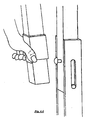
- FIG. 3 shows in isolation the two transverse struts 5 and 6, wherein the cross member 5 in the FIGS. 1 and 2 is articulated to the left recognizable side part 3, while the cross strut 6 is hinged to the opposite right side part 4.
- the two transverse struts 5, 6 each have a slot 15 and 16, however, wherein the slot 15 of the cross member 5 extends in the longitudinal direction of the cross member 5, while the slot 16 of the cross member 6 in the transverse end leg of the cross member 6 extends.
- This different arrangement of the slots is related to the desired different end positions, the transverse struts 5, 6 relative to the side parts 3 and 4 according to the FIGS. 1 and 2 can accept. The corresponding mechanism will be even better in FIG. 5 clarified.
- the cross member 5 is provided with an extended end portion, in which the end portion of the cross member 6 can engage appropriately.
- the cross strut 6 is provided with a pipe clamp 7, which is resiliently supported on the transverse strut 6.
- the cross struts 5, 6 engages the cross member 6 in the open end of the cross member 5 and the end of the cross member 5 presses the pipe clamp 7 against the resilient bias something back.
- the side part 3 or its corner post is provided with a U-shaped cross-section holding part, between whose U-legs, a pivot pin 12 extends.
- the pivot pin 12 also extends through a slot in the transverse strut at the same time 5, which extends in the longitudinal direction of the transverse strut 5.
- the transverse strut 5 In the in FIG. 5 In the upper left position shown, the transverse strut 5 is pivotable relative to the side part 3 about the pin 12.
- the cross strut 5 in the top left in FIG. 5 moved position shown down, so that the pin runs upwards in the slot, so the cross member 5 is located with a lying below the pivot portion on the side part 3 and can not, or at least be pivoted by a small angle. This relative position is in the FIGS.
- the cross strut 6, the in FIG. 5 is recognizable to the right, is in a similar manner in its perpendicular to the side part 4 aligned position (top right in FIG. 5 ) can be locked by also here the pivot pin is moved in a slot in a position in which the end leg of the cross member 6 abuts against the side part 4.
- the slot extends in this case perpendicular to the longitudinal direction of the cross member 6 in the beginning of the cross member 6 end legs.
- the cross member 6 relative to the side part 4 is pivotable.
- FIG. 6 shows in a series of single images 1-12, as the collapsed frame erected and in the example in FIG. 2e shown end position can be brought. The process essentially corresponds to that already in connection with the FIGS. 1 and 2 has been described.
- FIG. 7 shows a series of frames showing the folding of the frame. It should only be noted that, as for example in the sub-images 1 and 2 of FIG. 7 detects, the clamp 7 must be withdrawn and disengaged from the free end of the cross member 5 must be brought so that the cross member 5 pivoted upward and out of engagement with the free end of the cross member 6 can be brought. All other operations simply correspond to a reversal in the FIGS. 1a-e and 2a-e described operations.
- the side panels can be locked, if possible, to the vertical corner post 2 of the bottom part 1, so that the side parts 3, 4 after erecting even without connection of the crossbars are already held substantially perpendicular, even if they, for example, the flexible webs 8 of the pockets thereby can not sufficiently put under bias.
- the corner posts of the side part 3 and 4 are inserted into the corresponding corner posts 2 of the bottom part and can be unlocked simultaneously via a crossbar which connects two corner posts of each side part.
- FIG. 5 can also recognize the upper ends of the corner posts of the side parts 3 and 4 are expanded and correspond in cross section substantially the cross section of the corner posts 2 of the bottom part 1.
- the lower ends of the corner posts 2 of the bottom part 1 or additional approaches to the bottom part 1, with the corner posts 2 are aligned, however, correspond in their cross section substantially the corner posts of the side parts 3 and 4, so that these lower ends of the corner posts 2 and the corresponding extensions can be used to fit in the extensions of the corner posts of the side parts 3 and 4, as this in FIG. 5 are shown.
- This allows stacking of the collapsible racks both in the erected, that is unfolded state and in the folded state.
- the stacking in the unfolded state is also possible, inter alia, that the transverse struts 5, 6 are hinged below the upper free ends of the corner posts of the side parts 3 and 4 at this.
Landscapes
- Engineering & Computer Science (AREA)
- Mechanical Engineering (AREA)
- Pallets (AREA)
- Package Frames And Binding Bands (AREA)
- Carriages For Children, Sleds, And Other Hand-Operated Vehicles (AREA)
- Assembled Shelves (AREA)
- Passenger Equipment (AREA)
- Rigid Containers With Two Or More Constituent Elements (AREA)
- Tents Or Canopies (AREA)
Description
- Die vorliegende Erfindung betrifft ein zusammenklappbares Gestell für die Aufnahme und den Transport von in dem Gestell aufzunehmenden Taschen, die ihrerseits für die Aufnahme von zu transportierenden bzw. aufzubewahrenden Gegenständen vorgesehen sind, mit einem Bodenteil und seitlichen Rahmenteilen, die an ihrem unteren Ende gelenkig mit dem Bodenteil verbunden und gegenüber dem Bodenteil aus einer zum Bodenteil senkrechten Position in eine zum Bodenteil im wesentlichen parallele Position um etwa 90° oder mehr verschwenkbar sind.
- Ein entsprechendes Gestell ist beispielsweise aus der
deutschen Offenlegungsschrift Nr. 41 38 507 bekannt Bei dem bekannten Gestell sind jeweils ein starres oberes Rahmenteil und ein starres unteres Rahmenteil vorgesehen, damit an dem oberen starren Rahmenteil, das teilweise in Form paralleler Schienen ausgebildet ist, an diesen Schienen verschiebbare Stangen mit daran hängenden flexiblen Materialbahnen aufgehängt werden können. Die Seitenteile werden durch vier Eckpfosten definiert, die in der Mitte eine Gelenkstelle aufweisen und die jeweils gelenkig mit dem oberen Rahmenteil und dem unteren Rahmenteil verbunden sind, so daß die Pfosten jeweils in der Mitte zum Einknicken gebracht werden können und auf diese Weise das ganze Gestell zusammengeklappt werden kann. - Das bekannte Gestell ist jedoch dafür vorgesehen, nur im leeren Zustand, das heißt ohne die in dem Gestell aufgenommenen Taschen, zusammengeklappt zu werden. Außerdem ist das bekannte Gestell relativ aufwendig in der Herstellung, da jeder einzelne Pfosten insgesamt drei verschiedene Schamierstellen aufweisen muß, nämlich ein Scharnier gegenüber dem unteren Rahmenteil, ein Scharnier gegenüber dem oberen Rahmenteil und zusätzlich eine Knickstelle in der Mitte des Pfostens.
-
DE 200 12 639 U offenbart einen Gestell gemäß dem Oberbegriff des Anspruchs 1. Gegenüber diesem Stand der Technik liegt der vorliegenden Erfindung die Aufgabe zugrunde, ein zusammenklappbares Gestell zu schaffen, welches einfacher aufgebaut und leichter herzustellen ist. - Diese Aufgabe wird durch die Merkmale des Kennzeichnen den Teils des Anspruchs 1 gelöst.
- Auch beim Gegenstand der vorliegenden Erfindung bestehen die Seitenteile vorzugsweise im wesentlichen aus zwei parallelen und miteinander verbundenen Eckpfosten, wobei jedoch jeder der Eckpfosten nunmehr nur noch zwei Gelenkstellen aufweist, nämlich eine Gelenkstelle für die Verbindung mit dem Bodenteil und eine Gelenkstelle im oberen Bereich für die Verbindung mit der Querstrebe. Nach dem Aufrichten der Seitenteile werden die Querstreben der gegenüberliegenden Seitenteile aufeinander zu verschwenkt und in einem überlappenden Verbindungsbereich miteinander verbunden.
- Gemäß der Erfindung ist dabei vorgesehen, daß die freien Enden der Querstreben ineinandergreifen und durch eine den Eingriffsbereich übergreifende Rohrschelle im wesentlichen starr zusammengehalten werden.
- Dabei ist weiterhin in der bevorzugten Ausführungsform der Erfindung die Rohrschelle federnd an einer der Querstreben gehaltert und in Richtung des Verbindungsbereiches der beiden Querstreben vorgespannt, so daß beim Aufeinanderzuschwenken der beiden freien Enden der Querstreben diese zunächst ineinandergreifen, die federnd vorgespannte Rohrschelle dabei zunächst gegen die federnde Vorspannung zurückgedrängt wird und dann zurückschnappt und die Verbindungsstelle übergreift und so die beiden Enden der Querstreben zusammenhält.
- Auf diese Weise erzielt man relativ einfach eine starre Verbindung der beiden Querstreben und damit auch eine starre Verbindung der beiden Seitenteile, sofern auch die gelenkige Verbindung der Querstreben mit den Seitenteilen in dieser aufgeklappten Position keine relative Verschiebung zu den Querstreben zuläßt.
- Besonders bevorzugt ist eine Ausführungsform der Erfindung, bei welcher sich zwischen den Seitenteilen flexible Materialbahnen erstrecken, die beim Aufrichten der Seitenteile sich horizontal zwischen gegenüberliegenden Seitenteilen erstrecken und durch die sich aufrichtenden Seitentelle gespannt werden. Diese flexiblen Materialbahnen üben dann ihrerseits eine Zugkraft auf die Seitenteile aus und ziehen die Seitenteile aufeinander zu, während die Querstreben einen Mindestabstand der Seitenteile sicherstellen und damit die Position der Seitenteile eindeutig fixiert ist. Vorzugsweise sind mehrere Materialbahnen parallel zwischen den Seitenteilen gespannt und vorzugsweise sind auch die quer verlaufenden Materialbahnen durch im allgemeinen vertikal oder auch geneigt verlaufende Verbindungsbahnen miteinander verbunden, so daß zwischen den gespannten, horizontal verlaufenden Materialbahnen und den sich dazwischen erstreckenden Verbindungsbahnen Aufnahmetaschen für Gegenstände gebildet werden.
- Die Querstreben sind dabei vorzugsweise so bemessen, daß in dem aufgeklappten Zustand der Seitenteile dieselben sich im wesentlichen parallel zueinander und senkrecht zu dem Bodenteil erstrecken, wobei außerdem die die Seitenteile definierenden Eckpfosten mit entsprechenden Eckpfosten des Bodenteils ausgerichtet sind, so daß die aufgeklappten Gestelle aufeinander stapelbar sind.
- Dabei sind die Anlenkbereiche der Querstreben an den Seitenteilen bzw. deren Pfosten vorzugsweise so angeordnet, daß die oberen Enden der Pfosten frei bleiben und die oberen Enden der Eckpfosten der Seitenteile sowie die unteren Enden der Eckpfosten der Bodenteile sind vorzugsweise so ausgestaltet, daß sie beim Aufeinanderstapeln mehrerer Gestelle ineinandergreifen und dadurch gegen seitliche Verschiebung gesichert sind.
- In der bevorzugten Ausführungsform der Erfindung sind die oberen Enden der Eckpfosten des Bodenteiles ähnlich ausgebildet wie die oberen Enden der Eckpfosten der Seitenteile und außerdem sind die Seitenteile bzw. die Eckpfosten der Seitenteile an den Eckpfosten der Bodenteile so angelenkt, daß im zusammengeklappten Zustand des Gestells, wenn die Seitenteile heruntergeklappt sind, die oberen Enden der Eckpfosten der Bodenteile freiliegen. Die Eckpfosten der Bodenteile sind dabei im allgemeinen relativ kurze Pfostenstücke, die sich im wesentlichen senkrecht zu der ansonsten durch das Bodenteil definierten Ebene erstrecken. Diese Ausgestaltung ermöglicht es, daß auch die zusammengeklappten Gestelle aufeinander stapelbar sind.
- Zum Zusammenklappen, das heißt zum Einklappen der Seitenteile, kann es außerdem zweckmäßig sein, wenn die an den oberen Bereichen der Seitenteile bzw. der Eckpfosten der Seitenteile angelenkten Querstreben in eine Position parallel zu den Seitenteilen neben die Seitenteile bzw. neben die Eckpfosten der Seitenteile verschwenkbar und an diesen arretierbar sind. Ebensogut ist es auch möglich, daß zum Zusammenklappen des Gestells die Querstreben in eine Position verschwenkt werden, in der sie sich mehr oder weniger in Verlängerung der Seitenteile bzw. der Eckpfosten der Seitenteile erstrecken.
- Dabei ist außerdem eine Anlenkung der Querstreben an den Eckpfosten der Seitenteile in der Weise zweckmäßig, daß eines der Teile einen eine Achse definierenden Schwenkzapfen aufweist und das andere der Teile darauf mit einem Langloch aufgenommen ist, so daß die Querstrebe oder das entsprechende Gegenstück über das Langloch auf dem Zapfen verschiebbar ist und dadurch bestimmte Positionen der Querstreben relativ zu den Seitenteilen arretierbar sind.
- Weitere Vorteile, Merkmale und Anwendungsmöglichkeiten der vorliegenden Erfindung werden deutlich anhand der folgenden Beschreibung bevorzugter Ausführungsformen der dazugehörigen Figuren. Es zeigen:
- Figur 1a-e
- Prinzipskizzen eines zusammenklappbaren Gestells in verschiedenen Positionen,
- Figur 2a-e
- eine ähnliche Ausführungsform wie
Figur 1 , jedoch mit in dem Gestell aufgehängten Taschen, in ähnlichen Aufklappositionen wie inFigur 1a-e , - Figur 3
- die isoliert dargestellten Querstreben,
- Figur 4
- eine Skizze zur Veranschaulichung der Verbindung gegenüberliegender Querstreben,
- Figur 5
- Details der Verbindung zwischen dem oberen Bereich von Eckpfosten von Seitenteilen mit den Querstreben,
- Figur 6
- eine Serie von Bildern, welche das Aufrichten des erfindungsgemäßen Gestells zeigen und
- Figur 7
- eine Serie von Bildern, welche das Zusammenklappen des Gestells zeigen.
- Man erkennt in
Figur 1 in einer Seitenansicht das Bodenteil 1, mit kurzen, seitlich daran angesetzten Eckpfosten 2, Seitenteile 3, 4 und an den Seitenteilen 3, 4 angelenkten Querstreben 5 bzw. 6. - Es versteht sich, daß in der in
Figur 1 dargestellten, schematischen Seitenansicht jeweils nur die Vorderkanten des Bodenteils und der Seitenteile erkennbar sind, die vorzugsweise durch im allgemeinen aus Vierkantrohren bestehenden Querstreben bzw. Eckpfosten gebildet werden. Man kann sich anschaulich leicht vorstellen, daß in einer Ebene hinter der Papierebene nochmals die gleichen Elemente doppelt und parallel mit den Elementen der Papierebene durch Streben oder dergleichen verbunden sind und so insgesamt das Gestell bilden. - In
Figur 1a ist das Gestell vollständig zusammengeklappt. Als Besonderheit ist darauf hinzuweisen, daß dabei die Querstrebe 5 praktisch in Verlängerung zu dem Seitenteil 3 aufgeklappt ist und die Seitenteile 4 überdeckt, während die Querstrebe 6 parallel zum Seitenteil 4 zurückgeklappt und vorzugsweise an diesem arretiert ist. - In
Figur 1b ist das linke Seitenteil 3 aufgerichtet. InFigur 1c ist zusätzlich auch das rechte Seitenteil aufgerichtet, während die Querstreben noch ihre ursprüngliche Position relativ zu den Seitenteilen 3 bzw. 4 beibehalten haben, wie sie im zusammengeklappten Zustand besteht. - In
Figur 1d sind die Querstreben 5, 6 aufeinander zu verschwenkt und treten mit ihren freien Enden in Eingriff miteinander. Dabei ist eine Rohrschelle 7 erkennbar, die federnd an der Querstrebe 6 gelagert ist und die beim Ineinanderstecken der beiden freien Enden der Querstreben 5, 6 etwas zurückgedrängt wird und erst in der inFigur 1e dargestellten Position zurückschnappt und dabei die beiden miteinander verbundenen Enden der Querstreben 5, 6 übergreift. Auf diese Weise werden die Querstreben 5, 6 durch die übergreifende Rohrschelle 7 starr zusammengehalten. Es versteht sich, daß man zum Zusammenklappen des Gestells die Rohrschelle 7 nur nach rechts gegen die Kraft der federnden Vorspannung verschieben muß, um die beiden Enden der Querstreben 5, 6 wieder auseinanderbewegen zu können und dann in umgekehrter Reihenfolge das Gestell zusammenzuklappen. - Die
Figuren 2a-e zeigen genau den gleichen Ablauf des Zusammenklappens eines Gestells, wobei sich in diesem Fall das Gestell von dem Gestell derFigur 1 nur dadurch unterscheidet, daß sich zwischen den beiden Seitenteilen 3, 4 nunmehr parallele Bahnen 8 aus einem flexiblen Material erstrecken, die ihrerseits durch vertikale Verbindungsbahnen 9 miteinander verbunden sind, so daß zwischen den horizontalen Bahnen 8 und den vertikalen Bahnen 9 im wesentlichen rechteckige Taschen gebildet werden. Im zusammengeklappten Zustand gemäßFigur 2a und 2b hängen die Taschen noch lose zusammengefaltet zwischen den beiden Seitenteilen 3, 4 bzw. sie liegen auf dem Bodenteil 1 auf. Durch das Aufrichten der Seitenteile 3, 4 werden die horizontalen Bahnen 8 gespannt und erreichen ihre volle Spannung dann, wenn die beiden Querstreben 5, 6 zusammengeführt und starr miteinander verbunden sind, so daß sie die beiden Seitenteile 3, 4 auf einem vorgegebenen Mindestabstand halten, der so bemessen ist, daß in diesem Zustand die Materialbahnen 8 gerade straff gespannt sind. Außerdem sind die Querstreben auch so bemessen, daß sich in diesem Zustand die beiden Seitenteile 3, 4 bzw. deren Eckpfosten im wesentlichen parallel und senkrecht zur Ebene des Bodenteils und genau in der Verlängerung der kurzen Eckpfosten 2 des Bodenteiles erstrecken. -
Figur 3 zeigt isoliert die beiden Querstreben 5 und 6, wobei die Querstrebe 5 in denFiguren 1 und2 an dem links erkennbaren Seitenteil 3 angelenkt ist, während die Querstrebe 6 an dem gegenüberliegenden rechten Seitenteil 4 angelenkt ist. Man erkennt, daß die beiden Querstreben 5, 6 jeweils ein Langloch 15 bzw. 16 aufweisen, wobei sich allerdings das Langloch 15 der Querstrebe 5 in Längsrichtung der Querstrebe 5 erstreckt, während das Langloch 16 der Querstrebe 6 sich in dem quer verlaufenden Endschenkel der Querstrebe 6 erstreckt. Diese unterschiedliche Anordnung der Langlöcher hängt mit den gewünschten unterschiedlichen Endpositionen zusammen, die die Querstreben 5, 6 relativ zu den Seitenteilen 3 bzw. 4 gemäß denFiguren 1 und2 annehmen können. Der entsprechende Mechanismus wird noch besser inFigur 5 verdeutlicht. - In
Figur 4 erkennt man die Art der Verbindung der beiden Querstreben 5, 6 an ihren freien Enden. Im vorliegenden Beispiel ist die Querstrebe 5 mit einem erweiterten Endabschnitt versehen, in welchen der Endabschnitt der Querstrebe 6 passend eingreifen kann. Außerdem ist die Querstrebe 6 mit einer Rohrschelle 7 versehen, die an der Querstrebe 6 federnd gehaltert ist. Beim Zusammenstecken der beiden freien Enden der Querstreben 5, 6 greift die Querstrebe 6 in das offene Ende der Querstrebe 5 ein und das Ende der Querstrebe 5 drückt dabei die Rohrschelle 7 gegen deren federnde Vorspannung etwas zurück. Sobald die Querstreben 5, 6 die in denFiguren 1e bzw. 2e dargestellte, miteinander fluchtende Position erreicht haben, schnappt die Rohrschelle 7 aus ihrer federnd vorgespannten Position zurück und übergreift dabei auch einen Teil des Endabschnitts der Querstrebe 5, so daß zwischen diesen beiden Teilen eine starre Verbindung hergestellt wird. - In
Figur 5 erkennt man im linken Teilbild jeweils den Eckpfosten des Seitenteils 3 und die daran gelenkig angebrachte Querstrebe 5. Das Seitenteil 3 bzw. dessen Eckpfosten ist mit einem im Querschnitt U-förmigen Halteteil versehen, zwischen dessen U-Schenkeln sich ein Schwenkzapfen 12 erstreckt. Der Schwenkzapfen 12 erstreckt sich gleichzeitig auch durch ein Langloch in der Querstrebe 5, welches in Längsrichtung der Querstrebe 5 verläuft. In der inFigur 5 links oben dargestellten Position ist die Querstrebe 5 relativ zu dem Seitenteil 3 um den Zapfen 12 verschwenkbar. Wird jedoch die Querstrebe 5 in der oben links inFigur 5 dargestellten Position nach unten verschoben, so daß der Zapfen im Langloch nach oben läuft, so liegt die Querstrebe 5 mit einem unterhalb des Schwenkzapfens liegenden Abschnitt an dem Seitenteil 3 an und kann nicht, oder jedenfalls nur um einen kleinen Winkel verschwenkt werden. Diese relative Position ist in denFiguren 1a-c bzw.2a-c dargestellt. Nach dem Hochziehen der Querstrebe 5 in die inFigur 5 oben links dargestellte Position kann aber die Querstrebe 5 in die unten links inFigur 5 dargestellte Position verschwenkt werden. Aufgrund des an der Querstrebe 5 zusätzlich angesetzten Endschenkels schlägt aber auch dieser Endschenkel schließlich an dem Seitenteil 3 an und definiert so die dargestellte Position, in welcher die Querstrebe 5 sich im wesentlichen senkrecht zu dem Seitenteil 3 erstreckt. - Die Querstrebe 6, die in
Figur 5 rechts erkennbar ist, ist in ähnlicher Weise in ihrer senkrecht zu dem Seitenteil 4 ausgerichteten Position (oben rechts inFigur 5 ) arretierbar, indem auch hier der Schwenkzapfen in einem Langloch in eine Position verschoben wird, in welcher der Endschenkel der Querstrebe 6 an dem Seitenteil 4 anliegt. Das Langloch erstreckt sich in diesem Fall senkrecht zu der Längsrichtung der Querstrebe 6 in dem am Ende der Querstrebe 6 ansetzenden Endschenkel. In der unten inFigur 5 dargestellten Position des Zapfens in dem Langloch ist die Querstrebe 6 gegenüber dem Seitenteil 4 verschwenkbar. -
Figur 6 zeigt in einer Serie von Einzeibildern 1-12, wie das zusammengeklappte Gestell aufgerichtet und in die beispielsweise inFigur 2e dargestellte Endposition gebracht werden kann. Der Vorgang entspricht dabei im wesentlichen demjenigen, der bereits in Verbindung mit denFiguren 1 und2 beschrieben wurde. -
Figur 7 zeigt eine Serie von Einzelbildern, die das Zusammenfalten des Gestells zeigt. Hierbei ist lediglich zu beachten, daß, wie man beispielsweise in den Teilbildern 1 und 2 derFigur 7 erkennt, die Rohrschelle 7 zurückgezogen und außer Eingriff mit dem freien Ende der Querstrebe 5 gebracht werden muß, damit die Querstrebe 5 nach oben verschwenkt und außer Eingriff mit dem freien Ende der Querstrebe 6 gebracht werden kann. Alle weiteren Vorgänge entsprechen einfach einer Umkehrung der in denFiguren 1a-e und2a-e beschriebenen Vorgänge. - Wichtig ist dabei noch, daß die Seitenteile nach Möglichkeit auch an den vertikalen Eckpfosten 2 des Bodenteils 1 arretiert werden können, so daß die Seitenteile 3, 4 nach dem Aufrichten auch ohne Verbindung der Querstreben bereits im wesentlichen senkrecht gehalten werden, auch wenn sie beispielsweise die flexiblen Bahnen 8 der Taschen dadurch noch nicht ausreichend unter Vorspannung setzen können.
- Wie man in den Teilbildern 6 und 8 der
Figur 7 erkennen kann, sind die Eckpfosten der Seitenteil 3 bzw. 4 in die entsprechenden Eckpfosten 2 des Bodenteils eingesteckt und können über eine Querstange, die zwei Eckpfosten jedes Seitenteiles miteinander verbindet, gleichzeitig entriegelt werden. Wie man inFigur 5 außerdem erkennen kann, sind die oberen Enden der Eckpfosten der Seitenteile 3 und 4 aufgeweitet und entsprechen in ihrem Querschnitt im wesentlichen dem Querschnitt der Eckpfosten 2 des Bodenteils 1. Die unteren Enden der Eckpfosten 2 des Bodenteils 1 oder zusätzliche Ansätze am Bodenteil 1, die mit den Eckpfosten 2 ausgerichtet sind, entsprechen dagegen in ihrem Querschnitt im wesentlichen den Eckpfosten der Seitenteile 3 und 4, so daß diese unteren Enden der Eckpfosten 2 bzw. die entsprechenden Ansatzstücke passend in die Erweiterungen der Eckpfosten der Seitenteile 3 und 4 eingesetzt werden können, wie diese inFigur 5 dargestellt sind. Dies ermöglicht das Aufeinanderstapeln der zusammenklappbaren Gestelle sowohl im aufgerichteten, das heißt ausgeklappten Zustand als auch im zusammengeklappten Zustand. Das Aufeinanderstapeln im aufgeklappten Zustand wird unter anderem auch dadurch ermöglicht, daß die Querstreben 5, 6 unterhalb der oberen freien Enden der Eckpfosten der Seitenteilen 3 und 4 an diesen angelenkt sind.
Claims (10)
- Zusammenklappbares Gestell für die Aufnahme und den Transport von in dem Gestell aufzuhängenden Taschen, die ihrerseits für die Aufnahme von zu transportierenden bzw. aufzubewahrenden Gegenständen vorgesehen sind, mit einem Bodenteil (1) und seitlichen Rahmenteilen (3,4), die an ihrem unteren Ende gelenkig mit dem Bodenteil verbunden sind und gegenüber dem Bodenteil aus einer zum Bodenteil senkrechten Position in eine zum Bodenteil im wesentlichen parallele Position um etwa 90° oder mehr verschwenkbar sind, wobei am oberen Endbereich der seitlichen Rahmenteile jeweils eine Querstrebe (5, 6) angelenkt ist, die in Richtung aufeinander zu parallel zum Bodenteil verschwenkbar sind und deren freie Enden im wesentlichen starr miteinander verbindbar sind, so daß die oberen Enden der seitlichen Rahmenteile durch die starr verbundenen und an den oberen Bereichen der Seitenteile angelenkten Querstreben auf einem durch die Querstreben definierten Mindestabstand gehalten werden, dadurch gekennzeichnet, daß die freien Enden der Querstreben im miteinander verbundenen Zustand ineinandergreifen und durch eine den Verbindungsbereich übergreifende Rohrschelle (7) im wesentlichen starr zusammengehalten werden und daß die seitlichen Rahmenteile sich im aufgeklappten Zustand parallel zueinander und im wesentlichen senkrecht zum Bodenteil erstrecken, so daß gleichartige Gestelle mit miteinander ausgerichteten seitlichen Rahmenteilen aufeinander stapelbar sind.
- Zusammenklappbares Gestell nach Anspruch 1, dadurch gekennzeichnet, daß die Rohrschelle an einer der beiden Querstreben federnd gehaltert ist und in eine den Verbindungsbereich der Querstreben übergreifende Position vorgespannt ist.
- Zusammenklappbares Gestell nach einem der Ansprüche 1 oder 2, dadurch gekennzeichnet, daß zwischen den seitlichen Rahmenteilen mindestens zwei Bahnen (8) aus einem flexiblen Material angeordnet sind, die miteinander und/oder mit sich zwischen benachbarten Bahnen erstreckenden Verbindungsbahnen (9) Aufnahmetaschen für Gegenstände definieren, wobei die flexiblen Bahnen sich im aufgeklappten Zustand des Gestells horizontal unter Spannung zwischen den seitlichen Rahmenteilen erstrekken.
- Zusammenklappbares Gestell nach einem der Ansprüche 1 bis 3, dadurch gekennzeichnet, daß bei den aufeinandergestapelten Gestellen die oberen freien Enden der seitlichen Rahmenteile jeweils durch die oberen Enden von Eckpfosten definiert werden und daß die Bodenteile ebenfalls Eckpfosten (2) aufweisen, die bei aufgeklappten seitlichen Rahmenteilen mit den Eckpfosten der seitlichen Rahmenteile fluchten, wobei das untere Ende eines Eckpfostens des Bodenteils mit dem oberen Ende eines Eckpfosten eines seitlichen Rahmenteils bei aufeinandergestapelten Gestellen ineinandergreifen und so gegen seitliche Verschiebung gesichert sind.
- Zusammenklappbares Gestell nach Anspruch 4, dadurch gekennzeichnet, daß die oberen Enden der Eckpfosten (2) des Bodenteils ähnlich ausgestaltet sind wie die oberen Enden der Eckpfosten der seitlichen Rahmenteile und daß die seitlichen Rahmenteile so an den Eckpfosten der Bodenteile angelenkt sind, daß bei eingeklappten seitlichen Rahmenteilen die oberen Enden der Eckpfosten der Bodenteile freiliegen, so daß auch zusammengeklappte Gestelle verrutschungssicher aufeinander stapelbar sind.
- Zusammenklappbares Gestell nach einem der Ansprüche 4 oder 5, dadurch gekennzeichnet, daß eine der Querstreben parallel neben einem der Eckpfosten eines der seitlichen Rahmenteile verschwenkbar und an diesem arretierbar ist.
- Zusammenklappbares Gestell nach einem der Ansprüche 1 bis 6, dadurch gekennzeichnet, daß die durch die seitlichen Rahmenteile definierte Höhe des Gestells mindestens der Hälfte der durch den Abstand der aufgerichteten seitlichen Rahmenteile definierten Breite des Gestells beträgt.
- Zusammenklappbares Gestell nach einem der Ansprüche 1 bis 7, dadurch gekennzeichnet, daß an den seitlichen Rahmenteilen Spannvorrichtungen vorgesehen sind, durch welche sich zwischen den aufgerichteten seitlichen Rahmenteilen erstreckende flexible Materialbahnen unter Spannung gesetzt werden können bzw. deren Spannung erhöht werden kann.
- Zusammenklappbares Gestell nach einem der Ansprüche 1 bis 8, dadurch gekennzeichnet, daß die die seitlichen Rahmenteile definierenden Eckpfosten in Eckpfosten des Bodenteils gesteckt sind, deren Innenquerschnitt im wesentlichen dem Außenquerschnitt der Eckpfosten des Seitenteiles entspricht, wobei die Eckpfosten des Bodenteiles und die Eckpfosten des seitlichen Rahmenteils zusätzlich durch eine Zapfen-Langloch-Verbindung miteinander verbunden sind, wobei in einer Position des Schwenkzapfens im Langloch die Eckpfosten der seitlichen Rahmenteile und der Bodenteile in Ausrichtung miteinander arretiert sind und in der anderen Position des Schwenkzapfens im Langloch die Eckpfosten der seitlichen Rahmenteile gegenüber den Eckpfosten des Bodenteiles verschwenkbar sind.
- Zusammenklappbares Gestell nach einem der Ansprüche 1 bis 9, dadurch gekennzeichnet, daß die Anlenkstellen der Querstreben an den seitlichen Rahmenteilen so ausgestaltet sind, daß die Querstreben neben einem Mindestabstand gleichzeitig auch den Maximalabstand der seitlichen Rahmenteile definieren.
Applications Claiming Priority (3)
| Application Number | Priority Date | Filing Date | Title |
|---|---|---|---|
| DE20215597U | 2002-10-10 | ||
| DE20215597U DE20215597U1 (de) | 2002-10-10 | 2002-10-10 | Zusammenklappbares Gestell |
| PCT/EP2003/050698 WO2004035402A2 (de) | 2002-10-10 | 2003-10-07 | Zusammenklappbares gestell |
Publications (2)
| Publication Number | Publication Date |
|---|---|
| EP1554184A2 EP1554184A2 (de) | 2005-07-20 |
| EP1554184B1 true EP1554184B1 (de) | 2008-05-21 |
Family
ID=7975860
Family Applications (1)
| Application Number | Title | Priority Date | Filing Date |
|---|---|---|---|
| EP03808741A Expired - Lifetime EP1554184B1 (de) | 2002-10-10 | 2003-10-07 | Zusammenklappbares gestell |
Country Status (9)
| Country | Link |
|---|---|
| US (1) | US7878345B2 (de) |
| EP (1) | EP1554184B1 (de) |
| AT (1) | ATE396117T1 (de) |
| AU (1) | AU2003301271A1 (de) |
| CA (1) | CA2501060A1 (de) |
| DE (2) | DE20215597U1 (de) |
| ES (1) | ES2305566T3 (de) |
| PL (1) | PL200903B1 (de) |
| WO (1) | WO2004035402A2 (de) |
Families Citing this family (29)
| Publication number | Priority date | Publication date | Assignee | Title |
|---|---|---|---|---|
| DE20215597U1 (de) * | 2002-10-10 | 2003-04-10 | Conteyor Multibag Systems N.V., Merelbeke | Zusammenklappbares Gestell |
| DE10354182B4 (de) * | 2003-11-19 | 2011-10-06 | Kr-Porsiplast Verpackungssysteme Gmbh | Aufhängevorrichtung |
| US7083369B2 (en) | 2004-12-08 | 2006-08-01 | Bradford Company | Collapsible container with dunnage erection biaser |
| GR1005168B (el) * | 2005-03-04 | 2006-03-29 | Νικηφορος Ανδριανος | Πτυσσομενο εμπορευματοκιβωτιο-παλετα μεταφορας εμπορευματων. |
| EP1945523A1 (de) * | 2005-10-25 | 2008-07-23 | MACKENZIE, Noel Gordon | Palette mit zusammenlegbarem rahmen und beutel |
| US7802526B2 (en) * | 2007-03-05 | 2010-09-28 | Paccar Inc | Modular and customizable returnable rack system |
| US7770344B2 (en) * | 2007-10-03 | 2010-08-10 | Cooper Technologies Company | Under-floor cable support system |
| US20090289017A1 (en) * | 2008-05-21 | 2009-11-26 | Kraig Koeze | Transportable folding display rack |
| CA2692212A1 (en) * | 2008-05-23 | 2009-12-23 | Simpl Canada Ltd. | A frame for transporting, loading, unloading, and storing slabs |
| US20100011996A1 (en) * | 2008-07-18 | 2010-01-21 | Ecomedia Direct Inc. | Receptacle |
| US9683385B1 (en) | 2010-01-20 | 2017-06-20 | Doug Huesdash | Collapsible drink cabana |
| US20110253656A1 (en) * | 2010-04-15 | 2011-10-20 | Archie Vermeer | Modular collapsible gardening rack |
| GB201016758D0 (en) * | 2010-10-06 | 2013-07-24 | Sunrise Global Innovations Ltd | Collapsible garment stillage |
| CN104245474B (zh) * | 2012-01-24 | 2016-10-12 | 琳达·萝丝·林内尔 | 存储多个物体如托盘等的装置 |
| US9487329B2 (en) | 2013-03-25 | 2016-11-08 | Orbis Corporation | Sleeve pack assembly with latching mechanism |
| US8998011B2 (en) * | 2013-07-09 | 2015-04-07 | IP Power Holding Limited | Collapsible rack |
| US9572426B1 (en) * | 2013-11-11 | 2017-02-21 | Amazon Technologies, Inc. | Fabric pods |
| US9764876B2 (en) | 2015-01-02 | 2017-09-19 | Orbis Corporation | Sleeve pack assembly |
| US20160278516A1 (en) * | 2015-03-26 | 2016-09-29 | James Lawrence | Product shipping system |
| EP3093249B1 (de) * | 2015-05-09 | 2021-01-20 | SR2C Industrie Srl | Zusammenklappbarer behälter |
| US10336356B2 (en) * | 2016-06-22 | 2019-07-02 | Globe Composite Solutions, Ltd. | Wheeled shipping cart with stackable trays |
| US10543592B2 (en) * | 2016-07-06 | 2020-01-28 | Adam Esposito | Tool stand |
| WO2018039483A1 (en) * | 2016-08-24 | 2018-03-01 | Dane Technologies, Inc. | Stackable, collapsible pallets for transporting wheeled devices and related systems and methods |
| JP6813305B2 (ja) * | 2016-08-25 | 2021-01-13 | 株式会社ニッケンビルド | 搬送用パレット |
| CN108016796B (zh) * | 2017-12-25 | 2019-05-28 | 中国科学院沈阳自动化研究所 | 一种可折叠展开的空间货架 |
| US11577883B2 (en) | 2019-04-05 | 2023-02-14 | Orbis Corporation | Latch for a sleeve pack assembly |
| CN111086783A (zh) * | 2020-01-08 | 2020-05-01 | 中山顺隆集装箱袋有限公司 | 一种集装箱流体吨袋结构 |
| FI129559B (fi) | 2020-06-18 | 2022-04-29 | Hartwall K Oy Ab | Rullakko ja saman käsittävä logistiikkajärjestelmä |
| CN115624250B (zh) * | 2022-12-08 | 2023-04-18 | 唐山海港经济开发区医院 | 一种医疗各类药物存放设备 |
Family Cites Families (33)
| Publication number | Priority date | Publication date | Assignee | Title |
|---|---|---|---|---|
| US1216250A (en) * | 1916-03-10 | 1917-02-13 | John F Plander | Collapsible mail-rack. |
| US1394007A (en) * | 1921-01-03 | 1921-10-18 | Hall Mary Lucy | Collapsible wardrobe |
| US2517757A (en) * | 1946-12-05 | 1950-08-08 | Adlerstein Herman | Knapsack |
| US3519318A (en) * | 1968-05-27 | 1970-07-07 | Donald E Hagen | Camper's cupboard |
| DE2250812A1 (de) * | 1972-10-17 | 1974-04-25 | Mueller & Baum | Stapelpalette |
| US3810482A (en) * | 1972-11-14 | 1974-05-14 | Pelsue T Co | Collapsible tent and frame therefor |
| US3967327A (en) * | 1975-02-10 | 1976-07-06 | Severson Harvey M | Foldable bed |
| US4066089A (en) * | 1976-05-17 | 1978-01-03 | Rainwater Orman M | Collapsible shelter structure |
| US4270816A (en) * | 1979-01-23 | 1981-06-02 | Interface Design Group, Inc. | Furniture having prestressed fabric panels |
| US4382640A (en) * | 1980-12-11 | 1983-05-10 | Closet Systems Corp. | Portable storage shelf unit |
| US4735320A (en) * | 1986-11-03 | 1988-04-05 | Chrysler Motors Corporation | Shipping rack |
| ES2065364T3 (es) * | 1988-12-03 | 1995-02-16 | Bernhard Zich | Estanteria de varias partes. |
| DE4138507A1 (de) | 1991-11-23 | 1993-05-27 | Ieper Ind Nv | Vorrichtung fuer den transport und/oder die aufbewahrung von stueckgut |
| US5274980A (en) * | 1991-12-23 | 1994-01-04 | World Shelters, Inc. | Polyhedron building system having telescoping scissors |
| US5560502A (en) * | 1994-12-02 | 1996-10-01 | Hsiung; Yu-Kuang | Collapsible closet frame structure |
| US5957310A (en) * | 1995-10-11 | 1999-09-28 | Mitchell; Peter B. | Tensilely stressed storage furniture |
| US6089394A (en) * | 1996-07-22 | 2000-07-18 | Lamont Limited | Collapsible hamper for the storage of laundry and other items |
| US5833329A (en) * | 1996-10-03 | 1998-11-10 | Mcdonnell Douglas Corporation | Lightweight rack |
| DE19826429B4 (de) | 1998-06-16 | 2007-01-04 | Conteyor Multibag Systems N.V. | Vorrichtung für die Aufbewahrung und den Transport von Stückgut |
| DE19903297A1 (de) | 1998-07-16 | 2000-01-20 | Conteyor Multibag Systems Nv | Vorrichtung zur Aufbewahrung und zum Transport von Stückgut |
| US6089247A (en) * | 1998-08-12 | 2000-07-18 | Price; Walter L. | Collapsible frame |
| US6082386A (en) * | 1998-12-09 | 2000-07-04 | Patent Category Corp. | Vertically stacked collapsible structures |
| USD551452S1 (en) * | 1999-04-05 | 2007-09-25 | Bajer Design & Marketing, Inc. | Two compartment container |
| US6516823B1 (en) * | 1999-10-21 | 2003-02-11 | Cosco Management, Inc. | Playyard canopy |
| US6305764B1 (en) * | 2000-03-27 | 2001-10-23 | Production Assembly Service, Inc. | Industrial component holder assembly and rack |
| DE10016631A1 (de) | 2000-04-04 | 2001-10-11 | Tetra Laval Holdings & Finance | Fördervorrichtung mit Packungsträger |
| DE20012639U1 (de) * | 2000-07-19 | 2000-10-05 | Kaiser, Franz Andreas, 59846 Sundern | Ladegutsicherung für Europaletten |
| USD449447S1 (en) * | 2000-11-30 | 2001-10-23 | Bajer Design & Marketing, Inc. | Collapsible container |
| US6666223B2 (en) * | 2001-08-13 | 2003-12-23 | Walter L. Price | Collapsible frame |
| US6719157B2 (en) * | 2001-12-13 | 2004-04-13 | Rubbermaid Closet & Organization Products Company | Organizer |
| TW547585U (en) * | 2001-12-31 | 2003-08-11 | You-Tang Lin | Non-circular bar-shaped objects capable of adjusting length |
| DE20215597U1 (de) * | 2002-10-10 | 2003-04-10 | Conteyor Multibag Systems N.V., Merelbeke | Zusammenklappbares Gestell |
| US6766623B1 (en) * | 2003-03-18 | 2004-07-27 | Peter A. Kalnay | Foldable, expandable framework for a variety of structural purposes |
-
2002
- 2002-10-10 DE DE20215597U patent/DE20215597U1/de not_active Expired - Lifetime
-
2003
- 2003-10-07 WO PCT/EP2003/050698 patent/WO2004035402A2/de not_active Ceased
- 2003-10-07 DE DE50309896T patent/DE50309896D1/de not_active Expired - Lifetime
- 2003-10-07 AU AU2003301271A patent/AU2003301271A1/en not_active Abandoned
- 2003-10-07 EP EP03808741A patent/EP1554184B1/de not_active Expired - Lifetime
- 2003-10-07 US US10/528,884 patent/US7878345B2/en not_active Expired - Fee Related
- 2003-10-07 CA CA002501060A patent/CA2501060A1/en not_active Abandoned
- 2003-10-07 PL PL374980A patent/PL200903B1/pl not_active IP Right Cessation
- 2003-10-07 AT AT03808741T patent/ATE396117T1/de not_active IP Right Cessation
- 2003-10-07 ES ES03808741T patent/ES2305566T3/es not_active Expired - Lifetime
Also Published As
| Publication number | Publication date |
|---|---|
| US7878345B2 (en) | 2011-02-01 |
| AU2003301271A8 (en) | 2004-05-04 |
| CA2501060A1 (en) | 2004-04-29 |
| PL200903B1 (pl) | 2009-02-27 |
| AU2003301271A1 (en) | 2004-05-04 |
| PL374980A1 (en) | 2005-11-14 |
| ES2305566T3 (es) | 2008-11-01 |
| ATE396117T1 (de) | 2008-06-15 |
| EP1554184A2 (de) | 2005-07-20 |
| US20060138067A1 (en) | 2006-06-29 |
| WO2004035402A2 (de) | 2004-04-29 |
| WO2004035402A3 (de) | 2004-09-16 |
| DE50309896D1 (de) | 2008-07-03 |
| DE20215597U1 (de) | 2003-04-10 |
Similar Documents
| Publication | Publication Date | Title |
|---|---|---|
| EP1554184B1 (de) | Zusammenklappbares gestell | |
| DE69130538T4 (de) | Faltbare dachkonstruktion mit gelenkig verbundenen enden, die mit nichtzusammendrückbaren drehpunkten ausgestattet sind | |
| DE69032675T3 (de) | Schnell aufsetzbare, schnell faltbare, selbsttragende struktur | |
| DE60029306T2 (de) | Zusammenlegbarer behälter und zugehörige verbindungsvorrichtung | |
| DE3878013T2 (de) | Faltbare struktur. | |
| DE1809567A1 (de) | Gueterbehaelter | |
| DE3500427A1 (de) | Zusammenklappbarer transportkasten | |
| EP1473240A1 (de) | Stapelbarer Transportkasten | |
| DE1937997A1 (de) | Zusammenlegbare Gerueste | |
| EP1511411B1 (de) | Tisch für selbstbedienungsgeschäfte | |
| DE29606250U1 (de) | Anzeigeständer | |
| DE69016259T2 (de) | Einziehbare Säule. | |
| DE2853558A1 (de) | Zusammenlegbarer behaelter | |
| DE3782725T2 (de) | Faltbares gestaenge fuer anzeigetafeln. | |
| DE3600245A1 (de) | Geruest | |
| DE2436254B2 (de) | Zusammenklappbarer Transportkasten | |
| DE2430086A1 (de) | Palette mit seitenwaenden aus rohr- und/ oder drahtgitterrahmen | |
| DE2033724C3 (de) | Zusammenlegbare Kiste | |
| DE19800291A1 (de) | Falthaus | |
| DE4135677A1 (de) | Ladungstraeger | |
| DE9305904U1 (de) | Zusammenlegbarer Lager- und Transportkasten | |
| DE19520611C1 (de) | Zusammenklappbares Reisebett, insbesondere Kinderreisebett, oder dergleichen | |
| DE202006018857U1 (de) | Holzkiste | |
| DE29906231U1 (de) | Transport- / Lagerbehälter | |
| DE8122312U1 (de) | Kinderklappbett |
Legal Events
| Date | Code | Title | Description |
|---|---|---|---|
| PUAI | Public reference made under article 153(3) epc to a published international application that has entered the european phase |
Free format text: ORIGINAL CODE: 0009012 |
|
| 17P | Request for examination filed |
Effective date: 20050401 |
|
| AK | Designated contracting states |
Kind code of ref document: A2 Designated state(s): AT BE BG CH CY CZ DE DK EE ES FI FR GB GR HU IE IT LI LU MC NL PT RO SE SI SK TR |
|
| AX | Request for extension of the european patent |
Extension state: AL LT LV MK |
|
| DAX | Request for extension of the european patent (deleted) | ||
| GRAP | Despatch of communication of intention to grant a patent |
Free format text: ORIGINAL CODE: EPIDOSNIGR1 |
|
| GRAS | Grant fee paid |
Free format text: ORIGINAL CODE: EPIDOSNIGR3 |
|
| GRAA | (expected) grant |
Free format text: ORIGINAL CODE: 0009210 |
|
| AK | Designated contracting states |
Kind code of ref document: B1 Designated state(s): AT BE BG CH CY CZ DE DK EE ES FI FR GB GR HU IE IT LI LU MC NL PT RO SE SI SK TR |
|
| REG | Reference to a national code |
Ref country code: GB Ref legal event code: FG4D Free format text: NOT ENGLISH |
|
| REG | Reference to a national code |
Ref country code: CH Ref legal event code: EP |
|
| REF | Corresponds to: |
Ref document number: 50309896 Country of ref document: DE Date of ref document: 20080703 Kind code of ref document: P |
|
| REG | Reference to a national code |
Ref country code: RO Ref legal event code: EPE |
|
| REG | Reference to a national code |
Ref country code: IE Ref legal event code: FG4D Free format text: LANGUAGE OF EP DOCUMENT: GERMAN |
|
| REG | Reference to a national code |
Ref country code: SE Ref legal event code: TRGR |
|
| PG25 | Lapsed in a contracting state [announced via postgrant information from national office to epo] |
Ref country code: SI Free format text: LAPSE BECAUSE OF FAILURE TO SUBMIT A TRANSLATION OF THE DESCRIPTION OR TO PAY THE FEE WITHIN THE PRESCRIBED TIME-LIMIT Effective date: 20080521 |
|
| PG25 | Lapsed in a contracting state [announced via postgrant information from national office to epo] |
Ref country code: FI Free format text: LAPSE BECAUSE OF FAILURE TO SUBMIT A TRANSLATION OF THE DESCRIPTION OR TO PAY THE FEE WITHIN THE PRESCRIBED TIME-LIMIT Effective date: 20080521 |
|
| REG | Reference to a national code |
Ref country code: ES Ref legal event code: FG2A Ref document number: 2305566 Country of ref document: ES Kind code of ref document: T3 |
|
| NLV1 | Nl: lapsed or annulled due to failure to fulfill the requirements of art. 29p and 29m of the patents act | ||
| PG25 | Lapsed in a contracting state [announced via postgrant information from national office to epo] |
Ref country code: NL Free format text: LAPSE BECAUSE OF FAILURE TO SUBMIT A TRANSLATION OF THE DESCRIPTION OR TO PAY THE FEE WITHIN THE PRESCRIBED TIME-LIMIT Effective date: 20080521 |
|
| REG | Reference to a national code |
Ref country code: IE Ref legal event code: FD4D |
|
| PG25 | Lapsed in a contracting state [announced via postgrant information from national office to epo] |
Ref country code: PT Free format text: LAPSE BECAUSE OF FAILURE TO SUBMIT A TRANSLATION OF THE DESCRIPTION OR TO PAY THE FEE WITHIN THE PRESCRIBED TIME-LIMIT Effective date: 20081021 Ref country code: IE Free format text: LAPSE BECAUSE OF FAILURE TO SUBMIT A TRANSLATION OF THE DESCRIPTION OR TO PAY THE FEE WITHIN THE PRESCRIBED TIME-LIMIT Effective date: 20080521 Ref country code: DK Free format text: LAPSE BECAUSE OF FAILURE TO SUBMIT A TRANSLATION OF THE DESCRIPTION OR TO PAY THE FEE WITHIN THE PRESCRIBED TIME-LIMIT Effective date: 20080521 |
|
| PG25 | Lapsed in a contracting state [announced via postgrant information from national office to epo] |
Ref country code: SK Free format text: LAPSE BECAUSE OF FAILURE TO SUBMIT A TRANSLATION OF THE DESCRIPTION OR TO PAY THE FEE WITHIN THE PRESCRIBED TIME-LIMIT Effective date: 20080521 |
|
| PLBE | No opposition filed within time limit |
Free format text: ORIGINAL CODE: 0009261 |
|
| STAA | Information on the status of an ep patent application or granted ep patent |
Free format text: STATUS: NO OPPOSITION FILED WITHIN TIME LIMIT |
|
| 26N | No opposition filed |
Effective date: 20090224 |
|
| PG25 | Lapsed in a contracting state [announced via postgrant information from national office to epo] |
Ref country code: BG Free format text: LAPSE BECAUSE OF FAILURE TO SUBMIT A TRANSLATION OF THE DESCRIPTION OR TO PAY THE FEE WITHIN THE PRESCRIBED TIME-LIMIT Effective date: 20080821 Ref country code: EE Free format text: LAPSE BECAUSE OF FAILURE TO SUBMIT A TRANSLATION OF THE DESCRIPTION OR TO PAY THE FEE WITHIN THE PRESCRIBED TIME-LIMIT Effective date: 20080521 |
|
| PG25 | Lapsed in a contracting state [announced via postgrant information from national office to epo] |
Ref country code: MC Free format text: LAPSE BECAUSE OF NON-PAYMENT OF DUE FEES Effective date: 20081031 |
|
| REG | Reference to a national code |
Ref country code: CH Ref legal event code: PL |
|
| PG25 | Lapsed in a contracting state [announced via postgrant information from national office to epo] |
Ref country code: LI Free format text: LAPSE BECAUSE OF NON-PAYMENT OF DUE FEES Effective date: 20081031 Ref country code: CH Free format text: LAPSE BECAUSE OF NON-PAYMENT OF DUE FEES Effective date: 20081031 |
|
| PG25 | Lapsed in a contracting state [announced via postgrant information from national office to epo] |
Ref country code: AT Free format text: LAPSE BECAUSE OF NON-PAYMENT OF DUE FEES Effective date: 20081007 |
|
| PG25 | Lapsed in a contracting state [announced via postgrant information from national office to epo] |
Ref country code: CY Free format text: LAPSE BECAUSE OF FAILURE TO SUBMIT A TRANSLATION OF THE DESCRIPTION OR TO PAY THE FEE WITHIN THE PRESCRIBED TIME-LIMIT Effective date: 20080521 Ref country code: HU Free format text: LAPSE BECAUSE OF FAILURE TO SUBMIT A TRANSLATION OF THE DESCRIPTION OR TO PAY THE FEE WITHIN THE PRESCRIBED TIME-LIMIT Effective date: 20081122 Ref country code: LU Free format text: LAPSE BECAUSE OF NON-PAYMENT OF DUE FEES Effective date: 20081007 |
|
| PG25 | Lapsed in a contracting state [announced via postgrant information from national office to epo] |
Ref country code: GR Free format text: LAPSE BECAUSE OF FAILURE TO SUBMIT A TRANSLATION OF THE DESCRIPTION OR TO PAY THE FEE WITHIN THE PRESCRIBED TIME-LIMIT Effective date: 20080822 |
|
| PGFP | Annual fee paid to national office [announced via postgrant information from national office to epo] |
Ref country code: RO Payment date: 20100929 Year of fee payment: 8 |
|
| PGFP | Annual fee paid to national office [announced via postgrant information from national office to epo] |
Ref country code: IT Payment date: 20101025 Year of fee payment: 8 Ref country code: TR Payment date: 20101006 Year of fee payment: 8 Ref country code: GB Payment date: 20101021 Year of fee payment: 8 |
|
| PGFP | Annual fee paid to national office [announced via postgrant information from national office to epo] |
Ref country code: BE Payment date: 20111013 Year of fee payment: 9 Ref country code: FR Payment date: 20111103 Year of fee payment: 9 Ref country code: CZ Payment date: 20111003 Year of fee payment: 9 Ref country code: ES Payment date: 20111026 Year of fee payment: 9 Ref country code: SE Payment date: 20111021 Year of fee payment: 9 |
|
| PGFP | Annual fee paid to national office [announced via postgrant information from national office to epo] |
Ref country code: DE Payment date: 20111215 Year of fee payment: 9 |
|
| BERE | Be: lapsed |
Owner name: CONTEYOR MULTIBAG SYSTEMS N.V. Effective date: 20121031 |
|
| GBPC | Gb: european patent ceased through non-payment of renewal fee |
Effective date: 20121007 |
|
| REG | Reference to a national code |
Ref country code: FR Ref legal event code: ST Effective date: 20130628 |
|
| PG25 | Lapsed in a contracting state [announced via postgrant information from national office to epo] |
Ref country code: GB Free format text: LAPSE BECAUSE OF NON-PAYMENT OF DUE FEES Effective date: 20121007 Ref country code: CZ Free format text: LAPSE BECAUSE OF NON-PAYMENT OF DUE FEES Effective date: 20121007 Ref country code: BE Free format text: LAPSE BECAUSE OF NON-PAYMENT OF DUE FEES Effective date: 20121031 Ref country code: SE Free format text: LAPSE BECAUSE OF NON-PAYMENT OF DUE FEES Effective date: 20121008 Ref country code: DE Free format text: LAPSE BECAUSE OF NON-PAYMENT OF DUE FEES Effective date: 20130501 |
|
| REG | Reference to a national code |
Ref country code: DE Ref legal event code: R119 Ref document number: 50309896 Country of ref document: DE Effective date: 20130501 |
|
| PG25 | Lapsed in a contracting state [announced via postgrant information from national office to epo] |
Ref country code: FR Free format text: LAPSE BECAUSE OF NON-PAYMENT OF DUE FEES Effective date: 20121031 Ref country code: RO Free format text: LAPSE BECAUSE OF NON-PAYMENT OF DUE FEES Effective date: 20121007 Ref country code: IT Free format text: LAPSE BECAUSE OF NON-PAYMENT OF DUE FEES Effective date: 20121007 |
|
| REG | Reference to a national code |
Ref country code: ES Ref legal event code: FD2A Effective date: 20140207 |
|
| PG25 | Lapsed in a contracting state [announced via postgrant information from national office to epo] |
Ref country code: ES Free format text: LAPSE BECAUSE OF NON-PAYMENT OF DUE FEES Effective date: 20121008 Ref country code: TR Free format text: LAPSE BECAUSE OF NON-PAYMENT OF DUE FEES Effective date: 20121007 |