EP1553035B1 - Dispositif destiné à contenir et distribuer une feuille de recouvrement - Google Patents
Dispositif destiné à contenir et distribuer une feuille de recouvrement Download PDFInfo
- Publication number
- EP1553035B1 EP1553035B1 EP04000429A EP04000429A EP1553035B1 EP 1553035 B1 EP1553035 B1 EP 1553035B1 EP 04000429 A EP04000429 A EP 04000429A EP 04000429 A EP04000429 A EP 04000429A EP 1553035 B1 EP1553035 B1 EP 1553035B1
- Authority
- EP
- European Patent Office
- Prior art keywords
- blade
- cutting
- blade holder
- cover
- housing
- Prior art date
- Legal status (The legal status is an assumption and is not a legal conclusion. Google has not performed a legal analysis and makes no representation as to the accuracy of the status listed.)
- Expired - Lifetime
Links
- 230000001681 protective effect Effects 0.000 title 1
- 238000005520 cutting process Methods 0.000 claims abstract description 60
- 230000000873 masking effect Effects 0.000 claims abstract description 6
- 239000000463 material Substances 0.000 claims description 12
- 238000003825 pressing Methods 0.000 claims description 5
- 239000010408 film Substances 0.000 description 19
- 239000000853 adhesive Substances 0.000 description 9
- 230000001070 adhesive effect Effects 0.000 description 9
- 239000013039 cover film Substances 0.000 description 8
- 208000027418 Wounds and injury Diseases 0.000 description 4
- 230000006378 damage Effects 0.000 description 4
- 208000014674 injury Diseases 0.000 description 4
- 238000010422 painting Methods 0.000 description 4
- 230000015572 biosynthetic process Effects 0.000 description 3
- 239000011888 foil Substances 0.000 description 3
- 238000005755 formation reaction Methods 0.000 description 3
- 238000000034 method Methods 0.000 description 2
- 230000002093 peripheral effect Effects 0.000 description 2
- 238000005507 spraying Methods 0.000 description 2
- 210000003813 thumb Anatomy 0.000 description 2
- 239000011248 coating agent Substances 0.000 description 1
- 238000000576 coating method Methods 0.000 description 1
- 210000003811 finger Anatomy 0.000 description 1
- 210000004247 hand Anatomy 0.000 description 1
- 238000007373 indentation Methods 0.000 description 1
- 239000003973 paint Substances 0.000 description 1
- 238000005096 rolling process Methods 0.000 description 1
Images


Classifications
-
- B—PERFORMING OPERATIONS; TRANSPORTING
- B65—CONVEYING; PACKING; STORING; HANDLING THIN OR FILAMENTARY MATERIAL
- B65H—HANDLING THIN OR FILAMENTARY MATERIAL, e.g. SHEETS, WEBS, CABLES
- B65H35/00—Delivering articles from cutting or line-perforating machines; Article or web delivery apparatus incorporating cutting or line-perforating devices, e.g. adhesive tape dispensers
- B65H35/0006—Article or web delivery apparatus incorporating cutting or line-perforating devices
- B65H35/0073—Details
- B65H35/008—Arrangements or adaptations of cutting devices
- B65H35/0086—Arrangements or adaptations of cutting devices using movable cutting elements
-
- B—PERFORMING OPERATIONS; TRANSPORTING
- B65—CONVEYING; PACKING; STORING; HANDLING THIN OR FILAMENTARY MATERIAL
- B65H—HANDLING THIN OR FILAMENTARY MATERIAL, e.g. SHEETS, WEBS, CABLES
- B65H35/00—Delivering articles from cutting or line-perforating machines; Article or web delivery apparatus incorporating cutting or line-perforating devices, e.g. adhesive tape dispensers
- B65H35/0006—Article or web delivery apparatus incorporating cutting or line-perforating devices
- B65H35/002—Hand-held or table apparatus
-
- B—PERFORMING OPERATIONS; TRANSPORTING
- B65—CONVEYING; PACKING; STORING; HANDLING THIN OR FILAMENTARY MATERIAL
- B65H—HANDLING THIN OR FILAMENTARY MATERIAL, e.g. SHEETS, WEBS, CABLES
- B65H35/00—Delivering articles from cutting or line-perforating machines; Article or web delivery apparatus incorporating cutting or line-perforating devices, e.g. adhesive tape dispensers
- B65H35/04—Delivering articles from cutting or line-perforating machines; Article or web delivery apparatus incorporating cutting or line-perforating devices, e.g. adhesive tape dispensers from or with transverse cutters or perforators
- B65H35/06—Delivering articles from cutting or line-perforating machines; Article or web delivery apparatus incorporating cutting or line-perforating devices, e.g. adhesive tape dispensers from or with transverse cutters or perforators from or with blade, e.g. shear-blade, cutters or perforators
-
- B—PERFORMING OPERATIONS; TRANSPORTING
- B65—CONVEYING; PACKING; STORING; HANDLING THIN OR FILAMENTARY MATERIAL
- B65H—HANDLING THIN OR FILAMENTARY MATERIAL, e.g. SHEETS, WEBS, CABLES
- B65H2402/00—Constructional details of the handling apparatus
- B65H2402/40—Details of frames, housings or mountings of the whole handling apparatus
- B65H2402/44—Housings
- B65H2402/442—Housings with openings for introducing material to be handled, e.g. for inserting web rolls
-
- B—PERFORMING OPERATIONS; TRANSPORTING
- B65—CONVEYING; PACKING; STORING; HANDLING THIN OR FILAMENTARY MATERIAL
- B65H—HANDLING THIN OR FILAMENTARY MATERIAL, e.g. SHEETS, WEBS, CABLES
- B65H2402/00—Constructional details of the handling apparatus
- B65H2402/50—Machine elements
- B65H2402/54—Springs, e.g. helical or leaf springs
-
- B—PERFORMING OPERATIONS; TRANSPORTING
- B65—CONVEYING; PACKING; STORING; HANDLING THIN OR FILAMENTARY MATERIAL
- B65H—HANDLING THIN OR FILAMENTARY MATERIAL, e.g. SHEETS, WEBS, CABLES
- B65H2407/00—Means not provided for in groups B65H2220/00 – B65H2406/00 specially adapted for particular purposes
- B65H2407/10—Safety means, e.g. for preventing injuries or illegal operations
-
- B—PERFORMING OPERATIONS; TRANSPORTING
- B65—CONVEYING; PACKING; STORING; HANDLING THIN OR FILAMENTARY MATERIAL
- B65H—HANDLING THIN OR FILAMENTARY MATERIAL, e.g. SHEETS, WEBS, CABLES
- B65H2701/00—Handled material; Storage means
- B65H2701/10—Handled articles or webs
- B65H2701/17—Nature of material
- B65H2701/175—Plastic
- B65H2701/1752—Polymer film
-
- Y—GENERAL TAGGING OF NEW TECHNOLOGICAL DEVELOPMENTS; GENERAL TAGGING OF CROSS-SECTIONAL TECHNOLOGIES SPANNING OVER SEVERAL SECTIONS OF THE IPC; TECHNICAL SUBJECTS COVERED BY FORMER USPC CROSS-REFERENCE ART COLLECTIONS [XRACs] AND DIGESTS
- Y10—TECHNICAL SUBJECTS COVERED BY FORMER USPC
- Y10T—TECHNICAL SUBJECTS COVERED BY FORMER US CLASSIFICATION
- Y10T156/00—Adhesive bonding and miscellaneous chemical manufacture
- Y10T156/12—Surface bonding means and/or assembly means with cutting, punching, piercing, severing or tearing
-
- Y—GENERAL TAGGING OF NEW TECHNOLOGICAL DEVELOPMENTS; GENERAL TAGGING OF CROSS-SECTIONAL TECHNOLOGIES SPANNING OVER SEVERAL SECTIONS OF THE IPC; TECHNICAL SUBJECTS COVERED BY FORMER USPC CROSS-REFERENCE ART COLLECTIONS [XRACs] AND DIGESTS
- Y10—TECHNICAL SUBJECTS COVERED BY FORMER USPC
- Y10T—TECHNICAL SUBJECTS COVERED BY FORMER US CLASSIFICATION
- Y10T156/00—Adhesive bonding and miscellaneous chemical manufacture
- Y10T156/17—Surface bonding means and/or assemblymeans with work feeding or handling means
- Y10T156/1788—Work traversing type and/or means applying work to wall or static structure
- Y10T156/1795—Implement carried web supply
Definitions
- the invention relates to a device for storing and dispensing a rolled to a roll cover.
- Such devices are also referred to as foil wrapper dispensers. They facilitate the attachment of present in the form of a roll covering material on a surface and in particular for attaching a cover material which is provided on the longitudinal side at an edge or in the longitudinal edge region of the cover material with an adhesive portion.
- a conventional cover strip for example an ordinary adhesive strip with a limited adhesive effect can be used, which can be removed after painting.
- cover strips are sufficient for painting with smaller brushes or brushes.
- cover or release paper is often used in paint spraying, with a masking or adhesive strip along one edge of the paper and this partially overlapping. The adhesive strip and the paper adhered thereto are then adhesively attached to the desired location or surface.
- this procedure is tedious and time consuming. Further, the paper web tends to pull down the masking tape so that it is torn off the adherend, which is why the paper web often needs to be additionally held in place with tape pieces.
- Covering materials have already been proposed that consist essentially of a wide strip of paper or film and are provided on one longitudinal side with a self-adhesive adhesive.
- the foil strip is in the form of a supply roll. It is pulled from the roll and fastened by means of the adhesive side along the edge region of the surface to be covered.
- the cover material is applied by withdrawing an appropriate length from the supply roll, suitably simultaneously fixing the adhesive portion provided on the surface to be protected. Subsequently, the unrolled film section is cut off from the roll with a pair of scissors or a knife.
- the cover material is pulled in sections from the drum or box, fastened with its edge provided with the adhesive to the surface to be protected, then pulled again a section of the drum and processed and so on until the desired surface portion is covered. Thereafter, the processed web along the cutting bar is cut from the roll.
- the arranged on said devices cutting means are usually sharp and therefore handle with care to avoid injury.
- US-A-2003/0140760 an apparatus for storing and dispensing a present in the form of a roll cover is known, is formed with a housing body which encloses a roll space and of a housing bottom and a housing cover.
- This housing body has a dispenser slot, through which the unrolled end of the cover is feasible. It is a parallel cutting slot provided over which the end portion of the unrolled cover sheet is laid.
- a holder guide is arranged, in which a blade holder of a cutting device with a blade acting on both sides in the direction of the cutting slot held blade holder along the cutting slot is movable.
- the cutter further includes means for maintaining the blade in a retracted position when not in use.
- the end of the film roll rests on a support against which an upper stop with the transverse cutting device is pressed.
- the blade projects beyond the surface of the stopper (see Fig. 5).
- the blade may be pushed down by a spring to hold the blade in a retracted position when not in use. The risk of injury to an operator by the protruding blade is still present.
- the invention is so far the object of the one hand to provide a device or device, whereby a simplified and improved attachment of a present in the form of a cover material is possible and achieved, and on the other hand, the risk of injury is reduced by the cutting device of the device to a minimum.
- FIG. 1 shows an example of a preferred embodiment of the covering film dispenser according to the invention in a perspective representation.
- the cover sheet dispenser 1 consists essentially of a housing body, which consists of a housing bottom 2 and a Housing cover 3 is composed, as well as a cutting device 4.
- the housing body 1 encloses the roller space 5, in which the present in the form of a roll cover sheet 6 is inserted.
- the cross section of the housing body 1 is approximately drop-shaped or beak-shaped, which is approximately circular at the rear and converges towards the front.
- the housing cover 3 is articulated on its two side surfaces on the housing bottom 2 and can be about the axis A, which coincides with the axis of the film roll 6, pivot.
- the cutting device 4 consists of a blade holder guide 7 which extends in the front region of the housing cover 3 over its entire width and a blade holder 9 (see FIG. 2) arranged movably and spring-loaded in the blade holder guide 7 with a blade and of guide elements in the interior of the housing body 1
- the cutting device 4 is arranged completely inside the housing body 1, that is to say that the blade is moved in the interior of the housing during the cutting process and is completely covered by the housing body, which enables safe working with the covering film dispenser.
- FIG. 2 shows a schematic representation of a partially cut housing cover 3 with the cutting device 4.
- the blade holder guide is formed by a shaft 14 in the housing cover 3.
- two U-shaped profiles 16, 17 are arranged parallel to the axis A.
- the two profiles 16,17 are the guide elements of the blade holder 9.
- the two profiles 16, 17 are spaced from each other so that they form a downwardly open guide slot 18 for the blade 15 of the cutting device 4 in the shaft bottom.
- the cutting device 4 thus has the blade holder 9 with the blade 15 clamped at the lower end.
- a leaf spring 13 is arranged, which engages at the upper end of the shaft 14 in parallel to the surface of the housing cover 3 extending slots (not shown).
- this leaf spring 13 of the blade holder is spring-loaded in the vertical direction and is upwards in the direction Housing cover 3 pressed.
- the blade holder holder 10 forms the upper end of the blade holder 9.
- the blade holder 9 can be moved along the shaft 14 or along the guide slot 18.
- the height of the blade holder 9 and the length of the blade 15 are designed so that the blade 15 does not project downwards from the guide slot 18 when the blade holder 9 is not pressed. Only when the spring-loaded blade holder 9 is pressed downwards in the direction of the housing bottom 2 when cutting, the blade 15 protrudes from the guide slot 18. This has the advantage that the blade 15 protrudes from the guide slot 18 only during the cutting process.
- the blade holder 9 has at its lower end runners 19, 20 which engage in the downward pressing of the blade holder 9 on the one hand in the U-shaped profiles 16, 17 and on the other hand rest on the upper edges of the U-shaped profiles 16, 17.
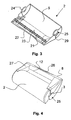
- FIG. 3 shows an open housing bottom 2.
- two webs 21 are arranged such that they lie exactly under a U-shaped profile 16, 17 of the shaft 14 when the housing cover 3 is closed.
- the gap between the two webs 21 forms the cutting slot 23.
- the cover sheet 6 is above the cutting slot 23 and is clamped between the webs 21 of the housing bottom 2 and the lower edges of the U-shaped profiles 16, 17.
- the U-shaped profiles 16, 17 are pressed against the webs 21, whereby the cover 6 is additionally held firmly (see also Figure 6).
- the pressed out of the guide slot 18 blade 15 now cuts when pulling the blade holder 9 along the cutting slot 23, the cover sheet 6.
- the blade holder 9 is released, the blade holder 9 is lifted with the blade 15 by the leaf spring 13 and the blade 15 is again in the guide slot 18.
- the housing body of the covering film dispenser 1 is shown from below.
- the rectangular, flat outer peripheral region 27 of the housing bottom allows the covering film dispenser 1 to be placed on flat surfaces without the device rolling away. This also allows another type of operation.
- the cover foil dispenser can be placed in the area to be covered, and you have both hands free for processing the cover and to operate the device.
- This peripheral area can additionally be provided with a non-slip coating in order to be able to deposit the covering film dispenser in a non-slip manner on a work surface.
- the front edge of the housing bottom has a slight indentation 26 along the dispenser slot. This recess 26 facilitates the gripping and opening of the housing cover 3 for tightening the cover 6.
- the blade holder 9 is shown in a perspective view.
- a leaf spring 13 is arranged, which engages in parallel to the surface of the housing cover 3 extending slots and presses the blade holder 9 upwards in the direction of the housing cover 3.
- This leaf spring 13 may, as shown in the preferred embodiment, be integrally formed on the blade holder 9 and made of the same material as the blade holder 9.
- the upper end of the blade holder 9 forms the blade holder handle 10.
- the blade 15 is inserted.
- the blade 15 extends pointedly downwards and has a cutting edge on both sides, so that the cutting device is effective in both directions and can be used in both directions for cutting off the covering film 6.
- skids 19, 20 which engage in the downward pressing of the blade holder 9 on the one hand in the U-shaped profiles 16, 17 and on the other hand rest on the upper edges of the U-shaped profiles 16, 17.
- the U-shaped profiles 16, 17 form a kind of rail for the blade holder 9, on which the blade holder 9 slides during cutting.
- an exact guidance of the blade 15 along the guide slot 18 and the cutting slot 23 is ensured.
- a shape can be seen, which forms the sliding body 27.
- the slider 27 rests with its vertical side surface 28 on the side wall of the shaft 14 and gives the blade holder 9 during cutting additional stability.
- FIG. 6 now shows a partial cross-section through the cutting device 4, the housing bottom 2 and the cover 3. It can be seen that the cover 3 is pressed against the housing bottom 2 when the blade holder 9 is pressed down (see arrows), and thus the film 6 between the U-shaped profiles 16, 17 and the webs 21, 22 is clamped, so that with the blade 15, a clean cut edge can be achieved.
- the size of the housing body 1 is chosen so that you can easily grasp the housing bottom 2 and the housing cover 3 with one hand.
- the two housing parts 2, 3 are additionally designed ergonomically with the recessed grip 12 in the housing base 2 and the handle strip 11 on the housing cover 3.
- the housing body 1 is gripped, for example, with the right hand such that the dispenser slot 8 is directed forward.
- the housing cover 3 is held with the thumb of the right hand and the other fingers of this hand grasp the housing bottom 2.
- the housing cover 3 is closed and the covering film required for the cover is pulled out of the covering film dispenser 1 through the dispenser slot 8.
- the cutting device 4 is actuated with the other hand by gripping the blade holder handle 10, pressing it towards the housing bottom 3 and pulling it to the opposite end of the blade holder guide 7. This completes the work process.
- the inventive cover sheet dispenser 1 allows a simple and easy attachment of a present in the form of a roll cover material.
- the risk of injury when working and handling the device is reduced to a minimum, since the blade 15 of the cutting device is located on the one hand inside the device, and thus shielded during the cutting process of the device housing, and on the other hand, the blade 15 when opening the device hidden by the guide slot 18 of the blade 15.
Landscapes
- Unwinding Webs (AREA)
- Details Or Accessories Of Spraying Plant Or Apparatus (AREA)
- Replacement Of Web Rolls (AREA)
- Vending Machines For Individual Products (AREA)
- Basic Packing Technique (AREA)
- Containers And Packaging Bodies Having A Special Means To Remove Contents (AREA)
Claims (6)
- Dispositif pour la conservation et le dévidage d'un film de couverture se présentant sous forme de rouleau avec un corps de boîtier (1) renfermant un compartiment à rouleau (5) avec un axe longitudinal (A) destiné à recevoir le rouleau (6) à installer et formé d'un fond du boîtier (2) et d'un couvercle de boîtier (3), et ce corps de boîtier (1) possède une fente de distribution (8) parallèle à l'axe longitudinal (A), à travers laquelle l'extrémité déroulée du film de couverture peut être passée, et avec une fente de découpe (23) parallèle à celle-ci, par-dessus laquelle la partie d'extrémité du film de couverture déroulé peut être posée, et il est prévu dans le couvercle de boîtier (3) un guide de support (7) dans lequel un porte-lame (9) d'un dispositif de coupe (4) doté d'une lame (15) agissant des deux côtés dans le sens de la fente de découpe (23) et retenue par le porte-lame (9) peut être déplacée le long de la fente de découpe (23), une couverture (18) pour la lame (15) étant formée dans le corps de boîtier (1) par deux profilés en forme de U (16, 17) disposés parallèlement à l'axe longitudinal (A) dans un renfoncement (14) du couvercle de boîtier (3) et écartés l'un de l'autre de telle manière qu'ils forment dans le fond du renfoncement une fente de guidage (18) ouverte vers le bas pour la lame (15) du dispositif de coupe (4), et le dispositif de coupe (4) possède des moyens (9, 13) qui retiennent la lame (15) non utilisée dans une position où la lame (15) est recouverte et qui ne permettent pas à la lame de coulisser dans la fente de découpe (23) dans le sens transversal par rapport au dispositif de coupe hors de la couverture.
- Dispositif selon la revendication 1, caractérisé en ce que pour le déplacement de la lame (15) transversalement par rapport au sens de coupe, il est prévu dans la partie d'extrémité supérieure du porte-lame (9) un ressort à lames (13) qui se met en prise à l'extrémité supérieure du renfoncement (14) dans des fentes parallèles à la surface du couvercle de boîtier 3 et contraint le porte-lame (9) en direction de la fente de découpe (23) vers le couvercle de boîtier (3) et positionne la lame (15) en la recouvrant dans la fente de guidage (18) lorsque le porte-lame (9) n'est pas contraint, et en ce que lorsque l'on appuie contre le porte-lame (9) dans la direction de la fente de découpe (23) la lame (15) peut sortir de la fente de guidage (18) et coulisser dans la fente de découpe (23).
- Dispositif selon la revendication 1 ou 2, caractérisé en ce que le porte-lame (9) possède à son extrémité inférieure des patins (19, 20) destinés à se mettre en prise, d'une part, lorsque le porte-lame (9) est enfoncé vers le bas, dans les profilés en forme de U (16, 17) pour garantir un guidage exact de la lame (15) le long de la fente de découpe (23) pendant l'opération de coupe, et à reposer d'autre part sur les bords supérieurs des profilés en forme de U (16, 17) pour appuyer ceux-ci contre la fente de découpe (23).
- Dispositif selon l'une des revendications précédentes, caractérisé en ce que le couvercle de boîtier (3) est articulé sur le fond du boîtier (2) de telle sorte que l'axe d'articulation coïncide avec l'axe longitudinal (A) du rouleau de film à déposer dans le compartiment à rouleau (5), et le couvercle de boîtier (3) est supporté de façon à pouvoir pivoter autour de cet axe longitudinal (A).
- Dispositif selon la revendication 4, caractérisé en ce qu'il est prévu au niveau des articulations (25) des barrettes (29) qui ont pour effet que lorsque le couvercle de boîtier (3) est ouvert, ses parois latérales peuvent être écartées au niveau des articulations (25) en direction de l'axe longitudinal (A).
- Dispositif selon l'une des revendications 2 à 5, caractérisé en ce que le ressort à lames (13) est fait du même matériau que le porte-lame (9) et formé d'un seul tenant sur celui-ci.
Priority Applications (4)
| Application Number | Priority Date | Filing Date | Title |
|---|---|---|---|
| EP04000429A EP1553035B1 (fr) | 2004-01-12 | 2004-01-12 | Dispositif destiné à contenir et distribuer une feuille de recouvrement |
| DE502004003600T DE502004003600D1 (de) | 2004-01-12 | 2004-01-12 | Vorrichtung zur Aufbewahrung und Abgabe einer Abdeckfolie |
| AT04000429T ATE360592T1 (de) | 2004-01-12 | 2004-01-12 | Vorrichtung zur aufbewahrung und abgabe einer abdeckfolie |
| US11/033,593 US20050150604A1 (en) | 2004-01-12 | 2005-01-12 | Apparatus for storing and dispensing a masking film |
Applications Claiming Priority (1)
| Application Number | Priority Date | Filing Date | Title |
|---|---|---|---|
| EP04000429A EP1553035B1 (fr) | 2004-01-12 | 2004-01-12 | Dispositif destiné à contenir et distribuer une feuille de recouvrement |
Publications (2)
| Publication Number | Publication Date |
|---|---|
| EP1553035A1 EP1553035A1 (fr) | 2005-07-13 |
| EP1553035B1 true EP1553035B1 (fr) | 2007-04-25 |
Family
ID=34585972
Family Applications (1)
| Application Number | Title | Priority Date | Filing Date |
|---|---|---|---|
| EP04000429A Expired - Lifetime EP1553035B1 (fr) | 2004-01-12 | 2004-01-12 | Dispositif destiné à contenir et distribuer une feuille de recouvrement |
Country Status (4)
| Country | Link |
|---|---|
| US (1) | US20050150604A1 (fr) |
| EP (1) | EP1553035B1 (fr) |
| AT (1) | ATE360592T1 (fr) |
| DE (1) | DE502004003600D1 (fr) |
Families Citing this family (9)
| Publication number | Priority date | Publication date | Assignee | Title |
|---|---|---|---|---|
| US8573278B1 (en) * | 2008-07-02 | 2013-11-05 | Bambi Lyn Cahilly | Well plate film applicator |
| DE202008015031U1 (de) * | 2008-11-13 | 2010-04-22 | Emsa Gmbh | Handabrollvorrichtung |
| DE102010017499A1 (de) * | 2010-06-21 | 2011-12-22 | Leifheit Ag | Einhandrollenschneider für Rollenware |
| GB2530994A (en) * | 2014-10-06 | 2016-04-13 | Wrapex Ltd | Film dispenser and method for manufacture thereof |
| CN205169998U (zh) * | 2015-10-27 | 2016-04-20 | 张丽群 | 一种折合式保鲜膜切割盒 |
| CN109733702B (zh) * | 2019-01-03 | 2023-09-08 | 东莞市南部佳永电子有限公司 | 全自动撕料设备 |
| CN111993838B (zh) * | 2020-09-03 | 2021-12-21 | 凤阳红指印建筑工程有限公司 | 一种室内墙壁纸粘贴辅助架 |
| USD990277S1 (en) * | 2021-07-02 | 2023-06-27 | Shenzhen Qi Jia You Ping Technology Co., Ltd | Cling wrap cutter |
| GB2622832A (en) * | 2022-09-29 | 2024-04-03 | Wrapex Ltd | A dispenser |
Family Cites Families (5)
| Publication number | Priority date | Publication date | Assignee | Title |
|---|---|---|---|---|
| ES2072755T3 (es) * | 1991-03-23 | 1995-07-16 | Melitta Haushaltsprodukte | Expendedor de laminas con dispositivo de separacion. |
| DE29709181U1 (de) * | 1997-05-24 | 1998-09-24 | Tmtape B.V., Gorinchem | Halter für Folienrollen für Mal- und Tapezierarbeiten |
| FR2771620B1 (fr) * | 1997-12-01 | 1999-12-31 | Maurice Granger | Appareil distributeur de papier d'essuyage |
| US6612215B2 (en) * | 2000-06-09 | 2003-09-02 | Max Co., Ltd. | Cutting machine |
| US20030140760A1 (en) * | 2002-01-25 | 2003-07-31 | Steven Bory | Film cutter |
-
2004
- 2004-01-12 DE DE502004003600T patent/DE502004003600D1/de not_active Expired - Fee Related
- 2004-01-12 EP EP04000429A patent/EP1553035B1/fr not_active Expired - Lifetime
- 2004-01-12 AT AT04000429T patent/ATE360592T1/de not_active IP Right Cessation
-
2005
- 2005-01-12 US US11/033,593 patent/US20050150604A1/en not_active Abandoned
Also Published As
| Publication number | Publication date |
|---|---|
| US20050150604A1 (en) | 2005-07-14 |
| EP1553035A1 (fr) | 2005-07-13 |
| DE502004003600D1 (de) | 2007-06-06 |
| ATE360592T1 (de) | 2007-05-15 |
Similar Documents
| Publication | Publication Date | Title |
|---|---|---|
| EP1553035B1 (fr) | Dispositif destiné à contenir et distribuer une feuille de recouvrement | |
| DE68912364T2 (de) | Vorrichtung zum Auftragen eines Abdeckmaterials. | |
| DE19923179C2 (de) | Messer | |
| DE69004995T2 (de) | Schnittkantenschutz. | |
| DE2752854A1 (de) | Werkzeug zum tapezieren | |
| DE4127048A1 (de) | Schneidvorrichtung zum aufschneiden einer gefalteten kante eines papierblatts oder dergleichen | |
| DE69314479T2 (de) | Handbetaetigte vorrichtung sowie verfahren zum einbringen eines elastomer-stranges unter einer dichtung | |
| DE3619050C2 (de) | Abdeckfolie sowie Aufnahmebehälter hiermit | |
| EP0290032B1 (fr) | Distributeur pour détacher un ruban tel qu'un bandage enroulé en simple ou en parallèle sur une bobine, en particulier sous forme de parties préproportionnées | |
| DE649833C (de) | Ausgeber von gummierten Klebestreifen | |
| DE19844448B4 (de) | Kleisterauftragsgerät | |
| EP0040679B1 (fr) | Dispositif pour appliquer des plaques | |
| DE4408901B4 (de) | Verfahren und Vorrichtung zum Behandeln von Zurichtebogen für Bandstahlschnitte | |
| DE4339151C2 (de) | Bandabrollvorrichtung | |
| DE19808538C2 (de) | Schneidvorrichtung und deren Verwendung | |
| DE9321258U1 (de) | Vorrichtung zur Aufnahme von Folienrollen und zum Abtrennen von Teilstücken der Folie | |
| DE2946950C2 (de) | Schneidegerät zum Öffnen von Kartonagen oder ähnlichen Verpackungen | |
| DE621959C (de) | Behaelter fuer Klebestreifenrollen | |
| DE19500237A1 (de) | Vorrichtung zum Schneiden von Bodenbelägen | |
| DE29723273U1 (de) | Kleisterauftragsgerät für Tapetenbahnen u.dgl. | |
| DE20303141U1 (de) | Vorrichtung zur Öffnung von Pappkartons | |
| DE3717081A1 (de) | Halterung fuer eine klebebandrolle | |
| DE2929422A1 (de) | Vorrichtung zum vorbereiten von bahnen von tapetenrollen | |
| DE2930473A1 (de) | Verpackung fuer folienbahn | |
| EP0650459B1 (fr) | Dispositif de reception de rouleaux de pellicules et de coupe de sections de la pellicule |
Legal Events
| Date | Code | Title | Description |
|---|---|---|---|
| PUAI | Public reference made under article 153(3) epc to a published international application that has entered the european phase |
Free format text: ORIGINAL CODE: 0009012 |
|
| AK | Designated contracting states |
Kind code of ref document: A1 Designated state(s): AT BE BG CH CY CZ DE DK EE ES FI FR GB GR HU IE IT LI LU MC NL PT RO SE SI SK TR |
|
| AX | Request for extension of the european patent |
Extension state: AL LT LV MK |
|
| 17P | Request for examination filed |
Effective date: 20060106 |
|
| AKX | Designation fees paid |
Designated state(s): AT BE BG CH CY CZ DE DK EE ES FI FR GB GR HU IE IT LI LU MC NL PT RO SE SI SK TR |
|
| GRAP | Despatch of communication of intention to grant a patent |
Free format text: ORIGINAL CODE: EPIDOSNIGR1 |
|
| GRAS | Grant fee paid |
Free format text: ORIGINAL CODE: EPIDOSNIGR3 |
|
| GRAA | (expected) grant |
Free format text: ORIGINAL CODE: 0009210 |
|
| AK | Designated contracting states |
Kind code of ref document: B1 Designated state(s): AT BE BG CH CY CZ DE DK EE ES FI FR GB GR HU IE IT LI LU MC NL PT RO SE SI SK TR |
|
| PG25 | Lapsed in a contracting state [announced via postgrant information from national office to epo] |
Ref country code: FI Free format text: LAPSE BECAUSE OF FAILURE TO SUBMIT A TRANSLATION OF THE DESCRIPTION OR TO PAY THE FEE WITHIN THE PRESCRIBED TIME-LIMIT Effective date: 20070425 |
|
| REG | Reference to a national code |
Ref country code: GB Ref legal event code: FG4D Free format text: NOT ENGLISH |
|
| REG | Reference to a national code |
Ref country code: IE Ref legal event code: FG4D Free format text: LANGUAGE OF EP DOCUMENT: GERMAN |
|
| REG | Reference to a national code |
Ref country code: CH Ref legal event code: EP |
|
| REF | Corresponds to: |
Ref document number: 502004003600 Country of ref document: DE Date of ref document: 20070606 Kind code of ref document: P |
|
| PG25 | Lapsed in a contracting state [announced via postgrant information from national office to epo] |
Ref country code: SE Free format text: LAPSE BECAUSE OF FAILURE TO SUBMIT A TRANSLATION OF THE DESCRIPTION OR TO PAY THE FEE WITHIN THE PRESCRIBED TIME-LIMIT Effective date: 20070725 |
|
| PG25 | Lapsed in a contracting state [announced via postgrant information from national office to epo] |
Ref country code: ES Free format text: LAPSE BECAUSE OF FAILURE TO SUBMIT A TRANSLATION OF THE DESCRIPTION OR TO PAY THE FEE WITHIN THE PRESCRIBED TIME-LIMIT Effective date: 20070805 |
|
| PG25 | Lapsed in a contracting state [announced via postgrant information from national office to epo] |
Ref country code: PT Free format text: LAPSE BECAUSE OF FAILURE TO SUBMIT A TRANSLATION OF THE DESCRIPTION OR TO PAY THE FEE WITHIN THE PRESCRIBED TIME-LIMIT Effective date: 20070925 |
|
| NLV1 | Nl: lapsed or annulled due to failure to fulfill the requirements of art. 29p and 29m of the patents act | ||
| GBV | Gb: ep patent (uk) treated as always having been void in accordance with gb section 77(7)/1977 [no translation filed] |
Effective date: 20070425 |
|
| REG | Reference to a national code |
Ref country code: IE Ref legal event code: FD4D |
|
| EN | Fr: translation not filed | ||
| PG25 | Lapsed in a contracting state [announced via postgrant information from national office to epo] |
Ref country code: CZ Free format text: LAPSE BECAUSE OF FAILURE TO SUBMIT A TRANSLATION OF THE DESCRIPTION OR TO PAY THE FEE WITHIN THE PRESCRIBED TIME-LIMIT Effective date: 20070425 Ref country code: BG Free format text: LAPSE BECAUSE OF FAILURE TO SUBMIT A TRANSLATION OF THE DESCRIPTION OR TO PAY THE FEE WITHIN THE PRESCRIBED TIME-LIMIT Effective date: 20070725 Ref country code: IE Free format text: LAPSE BECAUSE OF FAILURE TO SUBMIT A TRANSLATION OF THE DESCRIPTION OR TO PAY THE FEE WITHIN THE PRESCRIBED TIME-LIMIT Effective date: 20070425 Ref country code: NL Free format text: LAPSE BECAUSE OF FAILURE TO SUBMIT A TRANSLATION OF THE DESCRIPTION OR TO PAY THE FEE WITHIN THE PRESCRIBED TIME-LIMIT Effective date: 20070425 Ref country code: DK Free format text: LAPSE BECAUSE OF FAILURE TO SUBMIT A TRANSLATION OF THE DESCRIPTION OR TO PAY THE FEE WITHIN THE PRESCRIBED TIME-LIMIT Effective date: 20070425 Ref country code: SI Free format text: LAPSE BECAUSE OF FAILURE TO SUBMIT A TRANSLATION OF THE DESCRIPTION OR TO PAY THE FEE WITHIN THE PRESCRIBED TIME-LIMIT Effective date: 20070425 |
|
| PG25 | Lapsed in a contracting state [announced via postgrant information from national office to epo] |
Ref country code: SK Free format text: LAPSE BECAUSE OF FAILURE TO SUBMIT A TRANSLATION OF THE DESCRIPTION OR TO PAY THE FEE WITHIN THE PRESCRIBED TIME-LIMIT Effective date: 20070425 |
|
| PLBE | No opposition filed within time limit |
Free format text: ORIGINAL CODE: 0009261 |
|
| STAA | Information on the status of an ep patent application or granted ep patent |
Free format text: STATUS: NO OPPOSITION FILED WITHIN TIME LIMIT |
|
| 26N | No opposition filed |
Effective date: 20080128 |
|
| PG25 | Lapsed in a contracting state [announced via postgrant information from national office to epo] |
Ref country code: FR Free format text: LAPSE BECAUSE OF FAILURE TO SUBMIT A TRANSLATION OF THE DESCRIPTION OR TO PAY THE FEE WITHIN THE PRESCRIBED TIME-LIMIT Effective date: 20071221 Ref country code: IT Free format text: LAPSE BECAUSE OF FAILURE TO SUBMIT A TRANSLATION OF THE DESCRIPTION OR TO PAY THE FEE WITHIN THE PRESCRIBED TIME-LIMIT Effective date: 20070425 Ref country code: GB Free format text: LAPSE BECAUSE OF FAILURE TO SUBMIT A TRANSLATION OF THE DESCRIPTION OR TO PAY THE FEE WITHIN THE PRESCRIBED TIME-LIMIT Effective date: 20070425 Ref country code: GR Free format text: LAPSE BECAUSE OF FAILURE TO SUBMIT A TRANSLATION OF THE DESCRIPTION OR TO PAY THE FEE WITHIN THE PRESCRIBED TIME-LIMIT Effective date: 20070726 |
|
| PG25 | Lapsed in a contracting state [announced via postgrant information from national office to epo] |
Ref country code: RO Free format text: LAPSE BECAUSE OF FAILURE TO SUBMIT A TRANSLATION OF THE DESCRIPTION OR TO PAY THE FEE WITHIN THE PRESCRIBED TIME-LIMIT Effective date: 20070425 |
|
| BERE | Be: lapsed |
Owner name: RAY TECHNOLOGY GROUP B.V. Effective date: 20080131 |
|
| PG25 | Lapsed in a contracting state [announced via postgrant information from national office to epo] |
Ref country code: MC Free format text: LAPSE BECAUSE OF NON-PAYMENT OF DUE FEES Effective date: 20080131 |
|
| REG | Reference to a national code |
Ref country code: CH Ref legal event code: PL |
|
| PG25 | Lapsed in a contracting state [announced via postgrant information from national office to epo] |
Ref country code: LI Free format text: LAPSE BECAUSE OF NON-PAYMENT OF DUE FEES Effective date: 20080131 Ref country code: CH Free format text: LAPSE BECAUSE OF NON-PAYMENT OF DUE FEES Effective date: 20080131 Ref country code: DE Free format text: LAPSE BECAUSE OF NON-PAYMENT OF DUE FEES Effective date: 20080801 |
|
| PG25 | Lapsed in a contracting state [announced via postgrant information from national office to epo] |
Ref country code: FR Free format text: LAPSE BECAUSE OF FAILURE TO SUBMIT A TRANSLATION OF THE DESCRIPTION OR TO PAY THE FEE WITHIN THE PRESCRIBED TIME-LIMIT Effective date: 20070425 |
|
| PG25 | Lapsed in a contracting state [announced via postgrant information from national office to epo] |
Ref country code: EE Free format text: LAPSE BECAUSE OF FAILURE TO SUBMIT A TRANSLATION OF THE DESCRIPTION OR TO PAY THE FEE WITHIN THE PRESCRIBED TIME-LIMIT Effective date: 20070425 |
|
| PG25 | Lapsed in a contracting state [announced via postgrant information from national office to epo] |
Ref country code: BE Free format text: LAPSE BECAUSE OF NON-PAYMENT OF DUE FEES Effective date: 20080131 |
|
| PG25 | Lapsed in a contracting state [announced via postgrant information from national office to epo] |
Ref country code: AT Free format text: LAPSE BECAUSE OF NON-PAYMENT OF DUE FEES Effective date: 20080112 |
|
| PG25 | Lapsed in a contracting state [announced via postgrant information from national office to epo] |
Ref country code: CY Free format text: LAPSE BECAUSE OF FAILURE TO SUBMIT A TRANSLATION OF THE DESCRIPTION OR TO PAY THE FEE WITHIN THE PRESCRIBED TIME-LIMIT Effective date: 20070425 |
|
| PG25 | Lapsed in a contracting state [announced via postgrant information from national office to epo] |
Ref country code: HU Free format text: LAPSE BECAUSE OF FAILURE TO SUBMIT A TRANSLATION OF THE DESCRIPTION OR TO PAY THE FEE WITHIN THE PRESCRIBED TIME-LIMIT Effective date: 20071026 Ref country code: LU Free format text: LAPSE BECAUSE OF NON-PAYMENT OF DUE FEES Effective date: 20080112 |
|
| PG25 | Lapsed in a contracting state [announced via postgrant information from national office to epo] |
Ref country code: TR Free format text: LAPSE BECAUSE OF FAILURE TO SUBMIT A TRANSLATION OF THE DESCRIPTION OR TO PAY THE FEE WITHIN THE PRESCRIBED TIME-LIMIT Effective date: 20070425 |