EP1548263B1 - Trennblech für einlasskanal und sandkern zur formung des einlasskanals und zylinderkopf - Google Patents
Trennblech für einlasskanal und sandkern zur formung des einlasskanals und zylinderkopf Download PDFInfo
- Publication number
- EP1548263B1 EP1548263B1 EP04024658.9A EP04024658A EP1548263B1 EP 1548263 B1 EP1548263 B1 EP 1548263B1 EP 04024658 A EP04024658 A EP 04024658A EP 1548263 B1 EP1548263 B1 EP 1548263B1
- Authority
- EP
- European Patent Office
- Prior art keywords
- molten metal
- distal end
- cast
- side edges
- intake
- Prior art date
- Legal status (The legal status is an assumption and is not a legal conclusion. Google has not performed a legal analysis and makes no representation as to the accuracy of the status listed.)
- Expired - Fee Related
Links
Images


Classifications
-
- F—MECHANICAL ENGINEERING; LIGHTING; HEATING; WEAPONS; BLASTING
- F02—COMBUSTION ENGINES; HOT-GAS OR COMBUSTION-PRODUCT ENGINE PLANTS
- F02F—CYLINDERS, PISTONS OR CASINGS, FOR COMBUSTION ENGINES; ARRANGEMENTS OF SEALINGS IN COMBUSTION ENGINES
- F02F1/00—Cylinders; Cylinder heads
- F02F1/24—Cylinder heads
-
- F—MECHANICAL ENGINEERING; LIGHTING; HEATING; WEAPONS; BLASTING
- F02—COMBUSTION ENGINES; HOT-GAS OR COMBUSTION-PRODUCT ENGINE PLANTS
- F02B—INTERNAL-COMBUSTION PISTON ENGINES; COMBUSTION ENGINES IN GENERAL
- F02B31/00—Modifying induction systems for imparting a rotation to the charge in the cylinder
- F02B31/04—Modifying induction systems for imparting a rotation to the charge in the cylinder by means within the induction channel, e.g. deflectors
- F02B31/06—Movable means, e.g. butterfly valves
- F02B31/08—Movable means, e.g. butterfly valves having multiple air inlets, i.e. having main and auxiliary intake passages
-
- F—MECHANICAL ENGINEERING; LIGHTING; HEATING; WEAPONS; BLASTING
- F02—COMBUSTION ENGINES; HOT-GAS OR COMBUSTION-PRODUCT ENGINE PLANTS
- F02F—CYLINDERS, PISTONS OR CASINGS, FOR COMBUSTION ENGINES; ARRANGEMENTS OF SEALINGS IN COMBUSTION ENGINES
- F02F1/00—Cylinders; Cylinder heads
- F02F1/24—Cylinder heads
- F02F1/42—Shape or arrangement of intake or exhaust channels in cylinder heads
- F02F1/4235—Shape or arrangement of intake or exhaust channels in cylinder heads of intake channels
- F02F1/4242—Shape or arrangement of intake or exhaust channels in cylinder heads of intake channels with a partition wall inside the channel
-
- F—MECHANICAL ENGINEERING; LIGHTING; HEATING; WEAPONS; BLASTING
- F02—COMBUSTION ENGINES; HOT-GAS OR COMBUSTION-PRODUCT ENGINE PLANTS
- F02F—CYLINDERS, PISTONS OR CASINGS, FOR COMBUSTION ENGINES; ARRANGEMENTS OF SEALINGS IN COMBUSTION ENGINES
- F02F2200/00—Manufacturing
- F02F2200/06—Casting
-
- Y—GENERAL TAGGING OF NEW TECHNOLOGICAL DEVELOPMENTS; GENERAL TAGGING OF CROSS-SECTIONAL TECHNOLOGIES SPANNING OVER SEVERAL SECTIONS OF THE IPC; TECHNICAL SUBJECTS COVERED BY FORMER USPC CROSS-REFERENCE ART COLLECTIONS [XRACs] AND DIGESTS
- Y02—TECHNOLOGIES OR APPLICATIONS FOR MITIGATION OR ADAPTATION AGAINST CLIMATE CHANGE
- Y02T—CLIMATE CHANGE MITIGATION TECHNOLOGIES RELATED TO TRANSPORTATION
- Y02T10/00—Road transport of goods or passengers
- Y02T10/10—Internal combustion engine [ICE] based vehicles
- Y02T10/12—Improving ICE efficiencies
-
- Y—GENERAL TAGGING OF NEW TECHNOLOGICAL DEVELOPMENTS; GENERAL TAGGING OF CROSS-SECTIONAL TECHNOLOGIES SPANNING OVER SEVERAL SECTIONS OF THE IPC; TECHNICAL SUBJECTS COVERED BY FORMER USPC CROSS-REFERENCE ART COLLECTIONS [XRACs] AND DIGESTS
- Y10—TECHNICAL SUBJECTS COVERED BY FORMER USPC
- Y10T—TECHNICAL SUBJECTS COVERED BY FORMER US CLASSIFICATION
- Y10T29/00—Metal working
- Y10T29/49—Method of mechanical manufacture
- Y10T29/49229—Prime mover or fluid pump making
- Y10T29/49231—I.C. [internal combustion] engine making
Definitions
- the present invention relates to a partition plate for an intake port, a sand core for forming an intake-port and a cylinder head and, more particularly, to a partition plate for an intake port, a sand core for forming an intake-port and a cylinder head which are able to improve a precision in fixing position of a tumble plate in an intake port of a cylinder head.
- a cylinder of an internal combustion engine includes a cylinder head formed with an intake port in which a partition plate, called as a tumble plate, is set.
- Japanese Patent Application Laid-Open Publication No. 2001-193469 discloses a structure wherein an airflow control valve disposed in an intake-side distal end of an intake port is controlled while permitting a partition plate to deflect intake air, introduced from the intake port to a cylinder bore, for intensifying a tumble flow occurring inside the cylinder bore thereby to achieve improvement in fuel consumption.
- a side across which intake air, such as air and fuel gas, is passed is referred to as an "intake-side” and the opposite side, i.e., a cylinder bore side is referred to as a "cylinder-side”.
- the partition plate for the intake port is referred to as a "tumble plate”.
- the partition plate to pressurize or expand the core, causing cracks or damages to the core, whereby molten metal exudes through the cracks with resultant formation of burrs. Also, it is conceivable that due to thermal expansion of the partition plate, a locating position of the partition plate is adversely affected on the cast molding of the cylinder head and, additionally, there exists a probability for looseness of the partition plate to occur in the cylinder head, serving as a cast product, after completing the cast molding.
- the partition plate disclosed in Japanese Patent Application Laid-Open Publication No. 2001-193469 , is formed in a wave shape as measure to count the occurrence of deformation in the partition plate caused by thermal expansion, that would occur when the partition plate is cast in by molten metal, in cast molding the cylinder head.
- the partition plate with the wave shape is effective to absorb thermal expansion in a radial direction of the intake port, it cannot be said that such a partition plate has a capability to adequately absorb thermal expansion in an axial direction.
- the pressed products generally employ plate materials that have a relatively small surface roughness in order to properly perform press forming and, in addition to this, surfaces contaminated with lubricating films on press forming operations.
- a gripping force of the partition plate with respect to the cylinder head becomes low and looseness of the partition plate is apt to occur in the cast product.
- US 2002/078921 A1 relates to a variable tumble flow-generating device of an engine having a bulkhead provided in an intake port to divide the same into a first passage and a second passage. More specifically, the bulkhead has the slant surfaces for maintaining the air flow at the optimum condition, the grooves and the rugged portions for maintaining the air flow at the optimum condition, the working grooves for the valve guides, and the positioning hole for the assembly operation.
- the present invention has been completed upon such studies conducted by the present inventors and has an object to provide a partition plate for an intake port, a sand core for forming an intake-port and a cylinder head which are able to adequately eliminate positional displacement of the partition plate and looseness of the same in a cast product to achieve improvement in a product and additionally effectuate burrs, resulting from cracks of a core, to occur in limited regions to provide an ease of deburring work on subsequent processing.
- a partition plate for an intake port of a cylinder head to be manufactured by cast molding, which is preliminarily set prior to the cast molding in a sand core applied to form the intake port and then cast in when the cast molding is conducted so as to partition the intake port into a plurality of ports, comprising: an intake-side distal end; a cylinder-side distal end; a pair of side edges continuous with the intake-side distal end and the cylinder-sided distal end and to be cast in by molten metal when cast molding is conducted, each of the pair of side edges having end faces facing in a thickness direction and a side end face continuous with the end faces; and a promoter section provided on at least one of the side end face and the end faces of each of the pair of side edges to promote solidification of the molten metal.
- a cylinder head adapted to be manufactured by cast molding, comprising: a cylinder bore; an intake port connected to the cylinder bore; and a partition plate that is preliminarily set, prior to cast molding, in a sand core applied to form the intake port and then cast in when the cast molding is conducted so as to partition the intake port into a plurality of ports, the partition plate being provided with: an intake-side distal end; a cylinder-side distal end; a pair of side edges continuous with the intake-side distal end and the cylinder-sided distal end and to be cast in by molten metal when cast molding is conducted, each of the pair of side edges having end faces facing in a thickness direction and a side end face continuous with the end faces; and a promoter section provided on at least one of the side end face and the end faces of each of the pair of side edges to promote solidification of the molten metal.
- a method of manufacturing a cylinder head having a partition plate for an intake port comprising: preparing a partition plate including an intake-side distal end, a cylinder-side distal end, a pair of side edges continuous with the intake-side distal end and the cylinder-sided distal end to be cast in by molten metal when cast molding is conducted, and a promoter section provided on at least one of end faces, facing in a thickness direction, and a side end face, continuous with the end faces, of each of the pair of side edges to promote solidification of the molten metal; setting the partition plate in a sand core applied to form an intake port such that each of the pair of side edges is exposed outside; supplying molten metal onto each of the pair of side edges of the partition plate; solidifying the molten metal while promoting the solidification of the molten metal with the promoter section; and removing the sand core.
- a partition plate for an intake port of a cylinder head adapted to be manufactured by cast molding, which is preliminarily set, prior to the cast molding, in a sand core applied to form the intake port and then cast in when the cast molding is conducted so as to partition the intake port into a plurality of ports, comprising: an intake-side distal end; a cylinder-side distal end; a pair of side edges continuous with the intake-side distal end and the cylinder-sided distal end and to be cast in by molten metal when cast molding is conducted; and a surface treated section, provided on each of the pair of side edges, which is subjected to surface treatment in a coarse surface to have a coarser surface roughness than a surface roughness of a partitioning section by which an intake port is partitioned.
- a cylinder head adapted to be manufactured by cast molding, comprising: a cylinder bore; an intake port connected to the cylinder bore; and a partition plate that is preliminarily set, prior to cast molding, in a sand core applied to form the intake port and then cast in when the cast molding is conducted so as to partition the intake port into a plurality of ports, the partition plate being provided with: an intake-side distal end; a cylinder-side distal end; a pair of side edges continuous with the intake-side distal end and the cylinder-sided distal end and to be cast in by molten metal when cast molding is conducted; and a surface treated section, provided on each of the pair of side edges, which is subjected to surface treatment in a coarse surface to have a coarser surface roughness than a surface roughness of a partitioning section by which the intake port is partitioned.
- a method of manufacturing a cylinder head having a partition plate for an intake port comprising: preparing a partition plate including an intake-side distal end, a cylinder-side distal end, a pair of side edges continuous with the intake-side distal end and the cylinder-sided distal end and to be cast in by molten metal when cast molding is conducted, and a surface treated section provided on each of the pair of side edges and subjected to surface treatment in a coarse surface to have a coarser surface roughness than a surface roughness of a partitioning section by which an intake port is partitioned; setting the partition plate in a sand core to form the intake port such that each of the pair of side edges is exposed outside; supplying molten metal onto each of the pair of side edges of the partition plate; solidifying the molten metal while causing the surface treated section to be cast in; and removing the sand core.
- partition plates for intake ports, sand cores for forming intake-ports and cylinder heads of various embodiments according to the present invention are described in detail with suitable reference to the accompanying drawings.
- the same component parts of the several embodiments bear like reference numerals to omit or simplify description.
- a first embodiment according to the present invention is described below.
- a cylinder head 10 with a partition plate 100 for an intake port 14 is described.
- the partition plate 100 for the intake port 14 is also referred to as a "tumble plate 100".
- FIG. 1 is a schematic cross sectional view illustrating a cylinder head 10, of an engine, of the presently filed embodiment
- FIG. 2 is a cross sectional view taken on line perpendicular to an axis of the intake port 14 of the cylinder head 10
- FIG. 3 is a schematic view illustrating a flow current condition in the cylinder head 10
- FIG. 4 is a schematic plan view of the cylinder head shown in FIG. 3 .
- the cylinder head 10 is set on a top of a cylinder block 11 and has the intake port 14 for introducing intake airflow, composed of air and fuel gas delivered from an intake manifold 12, into a cylinder bore 13 and an exhaust port 15 through which exhaust gases resulting from combustion in the cylinder bore 13 are exhausted.
- the engine intake and exhaust structure is of the type, including one cylinder with four vales, which has two intake valves 16 and two exhaust valves 17.
- a tumble plate 100 Disposed inside the intake port 14 is a tumble plate 100 that extends along a direction (as shown by a series of whitened arrows FL in FIG. 3 ) in which intake air flows from an intake side (an outer terminal side in FIG. 3 ) toward the cylinder side.
- the intake manifold 12 Connected to the cylinder head 10 at the intake-side of the tumble plate 100 is the intake manifold 12 in which a control valve 18 is disposed as shown in FIGS. 3 and 4 .
- the intake port 14 is partitioned by the tumble plate 100 into an upper port 14u and a lower port 14d and on closing the lower port 14d with the control valve 18, intake air flows through the upper port 14u at an increased speed, resulting in the formation of strong vertical vortex flow, i.e., strong tumble flow, in the cylinder bore 13.
- the intake port 14 has a passage, closer to the cylinder, which is largely curved, and with a cylinder-side distal end Ta of the tumble plate 100 located at various incorrect positions, variations occur in characteristic of airflow current to remarkably and adversely affect a situation under which tumble flow is generated.
- the locating position of the cylinder-side distal end Ta forms an exceptionally important position.
- the locating position of the intake-side distal end Tb of the tumble plate 100 serves as a side at which intake air is divided and in which the control valve 18 is disposed.
- the intake-side distal end Tb of the tumble plate 100 needs not to be set at a higher precision than that required for the locating position of the cylinder-side distal end Ta.
- the presently filed embodiment is able to realize a structure wherein in cast molding the cylinder head 10, the cylinder-side distal end Ta is set to a fixed location whereas the intake-side distal end Tb is relatively free to assume various positions whereby even with the tumble plate 100 suffered from thermal affects on pouring molten metal, the thermal affects can be absorbed in regions closer to the intake-side distal end Tb.
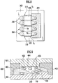
- FIGS. 5A and 5B are a plan view and a side view illustrating the tumble plate 100 of the presently filed embodiment. Also, throughout the drawings, x-, y- and z-axes designate a three-axis rectangular coordinate system.
- the tumble plate 100 is preliminarily set in an intake-port forming sand core 200 (see FIGS. 6A and 6B which will be described later in detail), by which the intake port 14 of the cylinder head 10 is formed, and cast in during the formation of the cylinder head 10 in cast molding to divide the intake port 14 into the plural ports (the upper port 14a and the lower port 14d).
- the tumble plate 100 has the both side edges Tc, which are cast in by molten metal, that have respective side end faces 101 each with a partial region formed with a solidification promoter portions 110 for promoting solidification of molten metal.
- the intake-port forming sand core 200 in which the tumble plate 110 is preliminarily set, will be also referred to as a "port core 200".
- the tumble plate 100 has a substantially rectangular configuration and is comprised of the both side edges Tc that are cast in by molten mental in cast molding the cylinder head 10, the intake-side distal end Tb that is contiguous with the both side edges Tc and is located upstream of the flow of intake air in the intake port 14, and the cylinder-side distal end Ta that is contiguous with the both side edges Tc and is located downstream of the flow of intake air in the intake port 14.
- An inside region, between the both side edges Tc, of the tumble plate 100 serves as a partitioning section 103 by which the intake port 14 is partitioned.
- reference numeral 102 designates end faces in a thickness direction (direction along the z-axis in FIG. 5B ) of the both side edges Tc of the tumble plate 100.
- the tumble plate 100 may be preferably made of material, such as aluminum alloy, in view of a weight and recycling capability.
- the tumble plate 100 may be formed of a thin-walled plate member to reduce resistance in flow of intake air passing across the intake port 14, for the tumble plate 100 made of material such as aluminum alloy, the tumble plate 100 may preferably have a thickness of a value equal to or greater than approximately 1.5mm when taking into consideration a need for precluding thermal distortion that would occur on heat treating a cast product of the cylinder head 10.
- tumble plate 100 No particular limitation is intended for a method of manufacturing the tumble plate 100 and for the purpose of simply fabricating cast products in equal quality at low costs, it may be preferable for the tumble plate 100 to be formed by press forming.
- the side end faces 101 have partial regions on which the respective promoter portions 110 are formed and with the presently filed embodiment, such partial regions are set to be closer to the cylinder-side distal end Ta.
- the promoter portions 110 are constituted by concave portions 111 formed on the respective side end faces 101 of the both side edges Tc.
- the concave portions 111 shown in the drawing figure, have semi-circular arc shapes, respectively.
- the concave portions 111 may be altered in the form of indents in various shapes, sizes, the number of pieces, locating positions and locating precisions on consideration of a locating precision, required for the tumble plate 100, and thermal expansion of the tumble plate 100.
- the intake-side distal end Tb of the tumble plate 100 may be chamfered. This is because there are probabilities where an end face of the cylinder head 10, to which the intake manifold 12 is connected, is processed by machining using cutters on a subsequent processing stage after cast molding the cylinder head 10 and the intake-side distal end Tb of the tumble plate 100 can be more smoothly cut away to minimize back burrs from occurring in machining operations.
- FIGS. 6A and 6B are a schematic plan view and a schematic side view illustrating a port core 200 in which the tumble plate 100 is preliminarily set.
- FIG. 7 is a schematic cross sectional view illustrating a mold 300 for molding the port core 200
- FIG. 8 is a schematic plan view illustrating a condition where the mold 300, for molding the port core 200, is cut away to allow the tumble plate 100 to be exposed.
- the mold 300 for molding the port core 200 will be hereinafter referred to as a "core mold 300".
- the port core 200 is set in a casting mold 400 (see FIG. 9 ), by which the cylinder head 10 is cast, to form the intake port 14 of the cylinder head 10 on solidifying molten metal.
- the tumble plate 100 is preliminarily set in the port core 200 with the both side edges Tc protruding outward to be cast in with molten metal.
- the both side edges Tc, protruding outward, of the tumble plate 100 play a role as regions to ensure the tumble plate 100 to be more reliably held when these regions are cast in by molten metal.
- the cast-in widths may be determined to lie in a value of approximately 2mm.
- the tumble plate 100 may suffer from adverse affects resulting from thermal shocks and vibrations occurring at repeated cycles in use on the engine.
- the tumble plate 100 is not fused to the cylinder head 10 and cast-in portions of the tumble plate 100 in the cylinder head 10 take the form of cutout shaped portions. For this reason, if the cast-in width increases in excess, a depth of the cutouts increases to cause stress concentration to occur at the cutout shaped portions, resulting in factors for causing deterioration in structural strength of the cylinder head 10.
- the tumble plate 100 has the both side edges Tc formed with the promoter portions 110, through which the solidification of molten metal is promoted, such that the solidification promoter section "a" on the both side edges Tc is possible to decrease the cast-in widths as small as possible. Accordingly, this results in a decrease in depth of the cutouts for minimizing the occurrence of stress concentration at the cutout shaped portions, resulting in an increase in a structural strength of the cylinder head 10. Therefore, the presence of the decreased wall thickness of the cylinder head 10 enables contribution to improvement in a cooling performance of the engine and lightweight structure.
- the core mold 300 is comprised of a plurality of mold segments such as a core-forming upper half and a core-forming lower half. With these mold segments brought into abutment, a mold cavity 303 is internally created for forming the port core 200. Core sand is blown into this mold cavity 303 and compacted, resulting in the formation of the port core 200.
- core sand is blown under a condition where the tumble plate 100 is preliminarily set in the core mold 300, thereby forming the port core 200.
- the tumble plate 100 is set in position with no displacement in the core mold 300 and located on a rest formed on a parting surface of the core-forming lower half 302. That is, the tumble plate 100 is held in the core mold 302 in such a manner that the marginal portions are set in a circumferential edge of the mold cavity.
- the port core 200 formed in the core mold 300, is taken out by separating the mold segments such as the core-forming upper half 301 and the core-forming lower half 302 in a separating direction, as shown by an arrow S in FIG. 7 , i.e., in a direction to cause the mold segments to separate from one another.
- reference numeral 201 designates a core print of the port core 200.
- FIG. 9 is a schematic cross sectional view illustrating a condition under which the port core 200 is set in the casting mold 400 for cast molding the cylinder head 10.
- the port core 200 is set in the casting mold 400 for cast molding the cylinder head 10.
- the casting mold 400 is comprised of an upper half mold 401, a lower half mold 402 and side molds 403, and the port core 200 is supported between the lower half mold 402 and the side molds 403 whereupon the casting mold 400 is closed by the upper half mold 401, thereby forming the mold cavity 404 in which the cylinder head 10 is cast molded.
- reference numeral "405" denotes cores for forming a water jacket. Examples of casting methods may include a low-pressure die-casting method (LPDC).
- LPDC low-pressure die-casting method
- pouring molten metal such as aluminum alloy
- pouring molten metal into the mold cavity 404 through a pouring gate (not shown) allows the cylinder head 10 to be formed as shown in FIG. 1 and on pouring molten metal, thermal expansion, caused by heat of molten metal, results in the tumble plate 100 set in the port core 200.
- the partial regions, closer to the cylinder-side distal end Ta, are formed with the respective promoter portions 110 that are formed of the concave portions 111, respectively.
- the promoter portions 110 serve as a key to promote the solidification of molten metal in the vicinity of the partial regions (on the solidification promoter section "a"), at which the promoter portions 110 are provided, further than that of molten metal in the vicinity of the other remaining region (on the flat and smooth section "b"). That is, rapidly solidifying molten metal in the vicinity of the solidification promoter section "a" provides an action to regulate a position at which the tumble plate 100 is located with respect to the intake port 14.
- the cores such as the port core 200, are removed, thereby obtaining the cylinder head 10 as a cast product.
- the solidification promoter section "a" closer to the cylinder-side distal end Ta has the surfaces, extending along the respective side end faces 101 of the both side edges Tc, i.e., the surfaces which extends in a longitudinal direction (a direction along the y-axis while varying in a direction along the x-axis), to have a contact area per unit length larger than that of the flat and smooth section "b" due to the presence of the concave portions 111.
- the partial regions closer to the cylinder-side distal end Ta are fixed in place faster than the other regions closer to the intake-side distal end Ta, thereby preventing the cylinder-side distal end Ta from being displaced with respect to the intake port 14.
- the solidification promoter section "a" is fixed in advance of the smoothed section “b” and the flat and smooth section “b” is fixed relatively slower than the solidification promoter section "a". For this reason, it becomes possible for a direction, in which the tumble plate 100 is caused to thermally expand due to heat of molten metal, to be limited or controlled to one direction in which molten metal moves from the solidification promoter section "a", at which molten metal begins to solidify, toward the flat and smooth section "b” where molten metal remains semi-solidified.
- the port core 200 is pressurized by the intake-side distal end Ta and the occurrence of cracks, which would occur in the port core 200, can be guided to or inducted to a region closer to the core print 201.
- burrs resulting from the cracks of the port core 200 do not occur in the inside of the cylinder head 10 as a cast product after completing the cast molding but in a product-profile outside region. Accordingly, this provides an ease of subsequent deburring work, or no need arises for carrying out such troublesome work.
- the tumble plate 100 is cast in at a high precision with the cylinder-side distal end Ta remaining in an important position.
- the positional displacement of the tumble plate 100 or looseness thereof inside the cast product can be adequately minimized to achieve improvement in a product quality and in addition, it becomes possible to provide an ease of deburring work in subsequent processing by causing burrs, resulting from the presence of cracks in the port core 200, to occur in partial regions.
- the cylinder-side distal end Ta of the tumble plate 100 can be located at a limit position with no occurrence of interference with a fuel injection region or a valve actuation region.
- FIGS. 10A and 10B are a schematic plan view and a schematic cross sectional view illustrating an outline of the intake port 14 of the cylinder head 10 to which a multi-point injection (MPI) type fuel injection unit is to be set
- FIGS. 10C and 10D are a schematic plan view and a schematic cross sectional view illustrating an outline of the intake port 14 of the cylinder head 10 to which a single-point injection (SPI) type fuel injection unit is to be set.
- MPI multi-point injection
- SPI single-point injection
- the cylinder-side distal end Ta can be located at the limit position with no occurrence of interference between the fuel injection regions 21 and the valve actuation regions 22.
- the cylinder-side distal end Ta can be located at the limit position with no occurrence with the valve actuation regions 22.
- the presence of the cylinder-side distal end Ta, located at the limit position with no interference with the fuel injection regions 21 or the valve actuation regions 22, enables desired tumble flow to reliably occur in the cylinder bore 13, enabling improvement in fuel consumption in a reliable manner.
- the promoter portions 110 may take the form of suitable configurations, as far as the solidification of molten metal is promoted, and may be constituted by convex portions or concave and convex portions formed on the side end faces 101 of the both side edges Tc. Also, the promoter portions 110 may take not only a semi-circular arc configuration but also other suitable configurations such as a triangular configuration or a rectangular configuration. An alternative may include the concave portions, convex portions and suitable combination between the concave portions and the convex portions, and different kinds of configurations may be combined in a mixture.
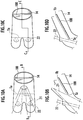
- FIGS. 11A and 11B are a schematic plan view and a schematic side view illustrating a port core 200a in which a tumble plate 100a of the presently filed embodiment is preliminarily set.
- the tumble plate 100a of the presently filed embodiment differs from the first embodiment in that regions (forming the solidification promoter section "a") of the both side edges Tc, in which the promoter portions 110 are provided, have a larger cast-in width than that of the other regions (forming the flat and smooth section "b") of the both side edges Tc whereas in the first embodiment, the both side edges Tc have a cast-in width in an equal value.
- regions (forming the solidification promoter section "a") of the both side edges Tc, in which the promoter portions 110 are provided have a larger cast-in width than that of the other regions (forming the flat and smooth section "b") of the both side edges Tc whereas in the first embodiment, the both side edges Tc have a cast-in width in an equal value.
- other structure is identical to the first embodiment.
- Such a cast-in width may be determined in a suitable dimension depending upon a wall thickness of the intake port 14 and a thickness of the tumble plate 100a and to take such one example, for the cast-in width LI of the smoothed portion 100a set in a value of approximately 2mm, the solidification promoter section "a" is set to have a cast-in width L2 in a value ranging from approximately 2.5mm to 3mm.
- the presence of the cast-in width L2 lying in an increased range at the solidification promoter section "a” results in an increase in a tight contact surface with the cylinder head 10, i.e., a cylinder head body, to cause the solidification promoter section "a" to be more firmly fixed in place, enabling to further increase a locating precision of the cylinder-side distal end Ta, forming an important position, with respect to the intake port 14.
- the tumble plate 100a since the tumble plate 100a has an increased area exposed to heat of molten metal to cause rapid increase in temperature of the tumble plate 100, the tumble plate 100a is able to extend far enough to a level available to absorb an increase in an extending length of the tumble plate 100a prior to the solidification of surrounding molten metal. This enables to further prevent the occurrence of cracks or damages to the port core 200.
- FIGS. 12A and 12B are a schematic plan view and a schematic side vice illustrating a port core 200b in which a tumble plate 100b of the present invention is preliminarily set.
- the tumble plate 100b of the presently filed embodiment differs from the first embodiment in that the presently filed embodiment takes the form of a structure wherein with the tumble plate 100b of the presently filed embodiment, the promoter portions 110 are formed on the respective side end faces 101 of the both side edges Tc at positions closer to the intake-side distal end Tb whereas in the first embodiment, the promoter portions 110 are located in the positions closer to the cylinder-side distal end Ta.
- the other structure is similar to that of the first embodiment.
- the intakes-de distal end Tb Depending upon a structure of the intake port 14 and the type of the fuel injection unit, it is probable for the intakes-de distal end Tb to satisfy requirements to be located at an increased precision. In such cases, it may be sufficed for the promoter portions 110 to be located on the side end faces 101 of the both side edges Tc at positions closer to the intake-side distal end Tb.
- a combination between the action for quenching molten metal through the promoter portions 110 and the action for causing molten metal to stay excels at promoting the solidification of molten metal in the vicinity of the solidification promoter section "a” than that of molten metal in the vicinity of the flat and smooth section "b".
- the regions closer to the intake-side distal end Tb of the both side edges Tc of the tumble plate 100b is fixed faster than the other regions closer to the cylinder-side distal end Ta, enabling to prevent the positional displacement of the intake-side distal end Tb with respect to the intake port 14.
- the promoter portions 110 may be located at any arbitrary positions in which an increased locating position is required. If a central position of the tumble plate is required to lie at an increased locating precision, the promoter portions 110 may be located at substantially central regions of the both side edges Tc in the longitudinal direction thereof.
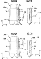
- FIGS. 13A and 13B are a schematic plan view and a schematic side vice illustrating a port core 200c in which a tumble plate 100c of the presently filed embodiment is preliminarily set.
- the tumble plate 100c of the presently filed embodiment differs from the first embodiment in a structure where concave portions 112, 113, corresponding to members for promoting the solidification of molten metal, are formed on entire regions of the side end faces 101 on the both side edges Tc of the tumble plate 100c so as to vary the degree in which the members 112, 113 promotes the solidification of molten metal along the longitudinal direction of the tumble plate 100c whereby the side end faces 101 have partial regions formed with the promoter portions 110 for relatively or substantially promoting the solidification of molten metal in contrast to the structure of the first embodiment wherein the concave portions 11 are formed in the specified regions of the tumble plate 100.
- the other structure is similar to that of the first embodiment.
- the locating precision required for the cylinder-side distal end Ta of the tumble plate 100c and the locating precision required for the intake-side distal end Tb differ from one another and, in addition, a need arises for a direction, in which the tumble plate 100c thermally expands due to heat of molten metal, to be limited or controlled to lie in one direction.
- the exemplary structure, shown in the drawing figures, has been exemplified where the cylinder-side distal end Ta is required to have a higher locating precision than that of the intake-side distal end Tb, and the concave portions 112 closer to the cylinder-side distal end Ta are designed in configurations to have larger indents than those of the concave portion 113 closer to the intake-side distal end Tb.
- the concave portions 112 with larger indents (hereinafter referred to as "large concave portions 112”) have relatively increased effect of quenching molten metal or of causing molten metal to stay further than those of the concave portions 113 with small indents 113 (hereinafter referred to as "small concave portions 113").
- the concave portions 112, 113 even on forming the concave portions 112, 113 on the entire regions of the side end faces 101 along the longitudinal direction of the tumble plate 100c, varying a size of indent configurations of the concave portions 112, 113 allows the promoter portions 110 to be relatively or substantially located on partial regions of the respective side end faces 101 of the both side edges Tc. That is, the partial regions in which the large concave portions 112 are formed play a role as the solidification promoter section "a".
- the both side edges Tc can be firmly fixed in place throughout the entire regions in the longitudinal direction.
- molten metal in the vicinity of the large concave portions 112, serving as the promoter portions 110 can be solidified faster than molten metal in the vicinity of the small concave portions 113.
- the regions closer to the cylinder-side distal end Ta of the both side edges Tc of the tumble plate 100c are fixed faster than the other regions closer to the intake-side distal end Tb, enabling the cylinder-side distal end Ta to be prevented from being displaced with respect to the intake port 14.
- a direction in which the tumble plate 100 thermally expands can be limited to a direction in which thermal expansion is directed toward the intake-side distal end Tb and no cracks or damages occur to the important regions for forming the shape of the intake port 14.
- the members for promoting the solidification of molten metal may be constituted by the concave portions 112, 113 and, in addition to these, convex portions and concave and convex portions in combination.
- an alternative may take the form of a structure wherein the indent configurations of the concave portions 112, 113 can be varied in size, as set forth above, and in addition to this, a structure wherein with a size remained unchanged, the number of pieces, locating positions and locating densities (in “coarse” and “dense” conditions) of the concave portions 112, 113 may be varied depending upon a degree at which the locating precision is required.
- an alternative may employ a structure for causing molten metal to be solidified at degree in two stages, a structure for causing molten metal to be solidified in stepwise degrees in more than three stages or in a structure for causing molten metal to be continuously solidified.
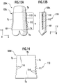
- FIG. 14 is a plan view illustrating a tumble plate 100d of the presently filed embodiment.
- nooks or corners of the concave portions 111, forming the promoter portions 110 are smoothly formed in round shapes 114, respectively.
- stamping can be simply carried out to form the concave portions 111 constituting the promoter portions 110, resulting in improvement in press forming capability.
- the promoter portions 110 excels at action for quenching molten metal and action for causing molten metal to stay for enabling the solidification of molten metal in the vicinity of the solidification promoter section "a” to be more promoted than that of molten metal in the vicinity of the flat and smooth section "b".
- This allows the both side edges Tc of the tumble plate 100d to be fixed faster than the flat and smooth section "b", regulating the locating position of the tumble plate 100d with respect to the intake port 14.
- FIGS. 15A and 15B are schematic plan views illustrating tumble plates 100e, 100f of the presently filed embodiment.
- the port core 200 is molded by blowing core sand into the mold cavity under a condition where the tumble plate 100 is preliminarily set in the core mold 300, it may be occasionally required for the left and right side marginal edges Tc of the tumble plate 100 to have different shapes and cast-in widths on consideration of a flowing behavior of molten metal.
- the tumble plate 100 with a distinction between both sides thereof, there is a need for the both sides of the tumble plate 100 to be orientated in correct orientations on forming the port core 200.
- tumble plates 100e, 100f it may be preferable for tumble plates 100e, 100f to take structures to prevent these from being erroneously placed in the core mold 300 like in the presently filed embodiment.
- the tumble plate 100e has one side formed with a notch 115 as shown in FIG. 15A and the tumble plate 100f have concave portions 111, forming the promoter portions 110, which are formed at non-symmetric positions on both side edges Tc as shown in FIG. 15B .
- FIGS. 16A and 16B are a plan view and a side view illustrating a tumble plate 100g of the presently filed embodiment.
- x-, y- and z-axes designate a three-axis rectangular coordinate system.
- the tumble plate 100g is of the type that is preliminarily set in an intake-port forming sand core 200g (see FIGS. 17A and 17B ), which will be described later, by which the intake port 14 of the cylinder head 10 is formed and, briefly describing, differs from the first embodiment in that promoter portions 120 for promoting the solidification of molten metal are formed on partial regions of the end faces 102 in a thickness direction (direction along the z-axis in FIG. 16B ) of the both side edges Tc of the tumble plate 100g.
- the other structure is identical to the first embodiment.
- the intake-port forming sand core 200g in which the tumble plate 100g is preliminarily set, is also referred to as a "port core 200g".
- the tumble plate 100g has a substantially rectangular shape and is comprised of the both side edges Tc that are cast in by molten metal in cast molding the cylinder head 10, the intake-side distal end Tb that is continuous with the both side edges Tc and disposed upstream of the flow of intake air inside the intake port 14, and the cylinder-side distal end Ta that is continuous with the both side edges Tc and disposed downstream of the flow of intake air.
- a region inside the both side edges Tc forms the partitioning section 103 by which the intake port 14 is partitioned.
- the promoter portions 120 are formed in partial regions of the end faces 102, in a thickness direction, of the both side edges Tc at positions closer to the cylinder-side distal end Ta.
- the promoter portions 120 include projections 121 formed on the end faces 102, facing in the thickness direction, of the both side edges Tc. It is needless to say that although the projections 121, shown as examples in the drawing figures, have columnar shapes, a shape, a size, the number of pieces, a locating position and a location density of the projections 121 may be altered in consideration of a locating precision required for the tumble plate 100g and thermal expansion of the tumble plate 100g.
- the partial regions at which the promoter portions 120 are located are also referred to as the solidification promoter section "a" and the other remaining region with no provision of the promoter portions 120 is also referred to as the flat and smooth section "b".
- FIGS. 17A and 17B are a schematic plan view and a schematic side view illustrating the port core 200g in which the tumble plate 100 g of the presently filed embodiment is preliminarily set.
- FIG. 18 is a schematic cross sectional view illustrating a mold 300g for molding the port core 200g
- FIG. 19 is a schematic plan view illustrating a condition wherein the mold 300g for molding the port core 200g are cut away to expose the tumble plate 100g.
- the mold 300g for molding the port core 200g is also referred to as a "core mold 300".
- the port core 200g is set in a casting mold 400g (see FIG. 20 that will be described later), by which the cylinder head 10 is cast, for forming the intake port 14 of the cylinder head 10.
- the port core 200g is preliminarily set such that the tumble plate 100g has both side edges Tc exposed outside to be cast in by molten metal.
- the both side edges Tc, exposed outside, of the tumble plate 100g serve as portions to ensure the both side edges Tc to be more reliably retained when the both side edges Tc are cast in by molten metal.
- Cast-in widths of the both side edges Tc are not particularly limited and may lie in a value of approximately 2mm. With the cylinder head 10 cast molded, the both side edges Tc of the tumble plate 100g are not fused to the cylinder head 10.
- the cast-in widths of the both side edges Tc can be made further smaller than those of the both side edges Tc formed with the concave portions, forming the promoter portions, as discussed in the first embodiment, thereby enabling the tumble plate 100g to further remarkably excel the above-described advantages such as the effect of increasing the structural strength of the cylinder head 10.
- the tumble plate 100g preliminarily set in the core mold 300g, core sand is blown into a mold cavity, thereby forming the port core 200g.
- the tumble plate 100g is positioned in a manner not to cause displacement of the tumble plate 100g in the core mold 300g and set on a rest formed on a parting surface of the core mold 300g. That is, the tumble plate 100g is held on a circumferential periphery of the mold cavity of the core-forming lower half 302.
- the port core 200g formed inside the core mold 300g is taken out by separating the mold segments, such as the core-forming upper half 301 and the core-forming lower half 302, in a separating direction as shown by an arrow S in FIG. 18 .
- FIG. 20 is a schematic cross sectional view illustrating a condition where the port core 200g is set in the casting mold 400g for casting the cylinder head 10.
- the port core 200g is set in the casting mold 400g for forming the cylinder head 10.
- pouring molten metal, such as aluminum alloy, into a mold cavity 404 from an in-gate (not shown) allows the cylinder head 10 to be cast molded and during such a pouring stage, thermal expansion results in the tumble plate 100g set in the port core 200g due to heat of molten metal.
- the partial regions closer to the cylinder-side distal end Ta are formed with the promoter portions 120 including the convex portions 121.
- the promoter portions 120 are effective to promote the solidification of molten metal in the vicinity of the partial regions (forming the solidification promoter section "a"), in which the promoter portions 120 are provided, further than the solidification of molten metal in the vicinity of the other region (flat and smooth section "b"), thereby regulating the locating position of the tumble plate 100g with respect to the intake port 14.
- the port core 200g in which the tumble plate 100g formed with such promoter portions 120 is preliminarily set, located in the casting mold 400g, pouring molten metal into the mold cavity 404 allows the both side edges Tc of the tumble plate 100g to be cast in with molten metal while causing molten metal to be solidified, permitting a whole of the both side edges Tc to be fixed in place.
- the cores such as the port core 200g, are removed, thereby obtaining the cylinder head 10 as a cast product.
- the solidification promoter section "a" due to the presence of the convex portions 121, of the both side edges Tc, the solidification promoter section "a", closer to the cylinder-side distal end Ta, have a larger contact area with molten metal at the end faces 102 than those of the flat and smooth section "b". For this reason, during a phase where the both ends Tc of the tumble plate 100g are cast in, molten metal in the vicinity of the solidification promoter section "a” is relatively quenched as compared to molten metal in the vicinity of the flat and smooth section "b", thereby promoting the solidification of molten metal.
- a combination between the action for quenching molten metal through the promoter portions 120 and the action for causing molten metal to stay excels at promoting the solidification of molten metal in the vicinity of the solidification.
- promoter section "a" further than the solidification of molten metal in the vicinity of the flat and smooth section "b".
- the regions of the both side edges Tc closer to the cylinder-side distal end Ta are fixed faster than the other region closer to the intake-side distal end Tb, enabling to preclude the cylinder-side distal end Ta from being displaced with respect to the intake port 14.
- the solidification promoter section "a" is fixed faster and the flat and smooth section “b” is fixed relatively slower than the solidification promoter section "a". Consequently, it becomes possible for the direction, in which the tumble plate 100g thermally expands due to heat of molten metal, to be limited or controlled to one direction in which molten metal is directed from the solidification promoter section "a", at which molten metal begins to solidify, toward the flat and smooth section "b” where molten metal remains un-solidified.
- the tumble plate 100g having the regions, closer to the cylinder-side distal end Ta, previously fixed, it becomes possible for the direction in which the tumble plate 100g thermally expands to be limited to the direction toward the intake-side distal end Tb.
- the thermal expansion of the tumble plate 100g is caused to intensively occur at the intake-side distal end Tb that is liable to expand, and no probabilities occur for the port core 200g to be pressurized by the cylinder-side distal end Ta.
- the port core 200g is pressurized by the intake-side distal end Tb, enabling cracks, which would occur in the port core 200g, to be guided to or induced to the core print 201. Burrs resulting from such cracks of the port core 200g do not occur in the cylinder head 10, as a cast product, after completing the cast molding but occurs in a product-profile outside region. Accordingly, subsequent deburring work can be easily carried out, or no need arises for carrying out such troublesome work.
- the tumble plate 100g can be precisely cast in with the locating position of the cylinder-side distal end Ta remaining in an important position.
- the positional displacement of the tumble plate 100g or looseness inside the cast product are adequately minimized to achieve improvement in a product quality and, additionally, it becomes possible to cause the burrs, resulting from cracks of the port core 200g, to occur in limited regions for thereby providing an ease of deburring work in subsequent processing.
- FIGS. 21A and 21B are a schematic plan view and a schematic side view illustrating a port core 200h in which a tumble plate 100h of the presently filed embodiment is preliminarily set.
- the tumble plate 100h of the presently filed embodiment differs from the seventh embodiment in that partial regions (solidification promoter section "a") of the both side edges Tc, on which the promoter portions 120 are provided, have larger cast-in widths than the other region (flat and smooth section "b") of the both side edges Tc whereas in the seventh embodiment, the both side edges Tc have equalized cast-in widths.
- the other structure is similar to the seventh embodiment.
- the cast-in widths may take various dimensions depending upon a thickness of a wall surface of the intake port 14 and a thickness of the tumble plate 100h and, to take one such example, for the flat and smooth section "b" with a cast-in width L1 lying in a value of approximately 2mm, a cast-in width L2 of the solidification promoter section "a" is determined to lie in a value ranging from approximately 2.5mm to 3mm.
- the tumble plate 100h is enabled to extend far enough to a level available to absorb an increase in an extending length of the tumble plate 100h prior to he solidification of surrounding molten metal. This enables cracks or damages to the port core 200h to be prevented from occurring in a further reliable manner.
- the both side edges Tc are possible to decrease the cast-in width as small as possible and, hence, even if the notch depth slightly increases due to the presence of a slight increase in the cast-in width like in the presently filed embodiment, it becomes possible to avoid factors for causing deterioration in a structural strength of the cylinder head 10.
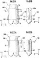
- FIGS. 22A and 22B are a schematic plan view and a schematic side view illustrating a port core 200i in which a tumble plate 100i of the presently filed embodiment is preliminarily set.
- the tumble plate 100i of the presently filed embodiment differs from the seventh embodiment in that partial regions, in which the promoter portions 120 of the end faces 102, facing in the thickness direction, of the both side edges Tc are provided, are set closer to the intake-side distal end Tb whereas in the seventh embodiment, the partial regions in which the promoter portions 120 are provided are set closer to the cylinder-side distal end Ta.
- Other structure is similar to the seventh embodiment.
- a combination between the action for quenching molten metal through the promoter portions 120 and the action for causing molten metal to stay excels at promoting the solidification of molten metal in the vicinity of the solidification promoter section "a” further than the solidification of molten metal in the vicinity of the flat and smooth section "b".
- the partial regions of the both side edges Tc closer to the intake-side distal end Tb are fixed faster than the other region closer to the cylinder-side distal end Ta, enabling the intake-side distal end Tb to be prevented from displacement with respect to the intake port 14.
- the promoter portions 120 may be located in such required partial regions.
- the promoter portions 120 may be located in substantially central regions of the both side edges Tc along the longitudinal direction thereof.
- FIGS. 23A and 23B are a schematic plan view and a schematic side view illustrating a port core 200j in which a tumble plate 100j of the presently filed embodiment is preliminarily set.
- the tumble plate 100j of the presently filed embodiment differs from the seventh embodiment in that projections 122, 123, corresponding to members for promoting the solidification of molten metal, are provided on entire regions of the end faces 102, facing in the thickness direction, of the both side edges Tc on varying distribution patterns and the degree at which the solidification of molten metal is promoted by the above members 122,123 is varied in a longitudinal direction (to vary in a direction along the x-axis and extending in a direction along the y-axis) to allow the partial regions of the end faces 102, facing in the thickness direction, of the tumble plate 100j to be relatively or substantially formed with the promoter portions 120 for promoting the solidification of molten metal whereas in the seventh embodiment, the projections 121 are located in the specified regions.
- Other structure is similar to the seventh embodiment.
- the cylinder-side distal end Ta is required to have a higher locating precision than that of the intake-side distal end Tb and the projections 122 closer to the cylinder-side distal end Ta are placed in a locating density under a "dense" condition while the projections 123 closer to the intake-side distal end Tb are placed in a locating density under a "coarse" condition.
- the projections 122 (hereinafter referred to as “dense projections 122") whose locating density is “dense” relatively have larger effects of quenching molten metal and causing molten metal to stay than those of the projections 123 (hereinafter referred to as “coarse projections 123”) whose locating density is "coarse”.
- the provision of the projections 122, 123 formed on the entire regions, in the longitudinal direction, of the end faces 102 facing in the thickness direction enables the entire regions of the end faces, along the longitudinal direction, of the both side edges Tc to be firmly fixed. Additionally, such a structure promotes the solidification of molten metal in the vicinity of the dense projections 122, which function as the promote: portions 120, further than the solidification of molten metal in the vicinity of the coarse projections 123.
- the both side edges Tc of the tumble plate 100j are effective to cause the regions closer to the cylinder-side distal end Ta to be fixed faster than those closer to the intake-side distal end Tb, enabling the cylinder-side distal end Ta to be prevented from displacement with respect to the intake port 14.
- a direction in which the tumble plate 100j thermally expands is limited to a direction toward the intake-side distal end Tb and no cracks or damage occur to an important region, of the tumble plate 100 j, for forming the shape of the intake port 14.
- the members for promoting the solidification of molten metal may be constituted by the projections 122, 123 described above and, in addition to these, concave portions, concave and convex portions and through-bores may be adopted.
- the projections 122, 123 may be located in varying densities as set forth above and, in addition to this, an alternative may include the form of a structure wherein a size (in diameter and height) and a locating position are varied depending upon the degree of required locating precision.
- the tumble plate 100j may be formed in any one of a structure where the promoting degree is varied on two stages, another structure where the promoting degree is varied stepwise in more than three stages or the other structure where the promoting degree is continuously varied.
- FIGS. 24A and 24B , FIGS. 25A and 25B , FIGS. 26A and 26B and FIGS. 27A and 27B are schematic plan views and schematic side views illustrating port cores 200h to 200n in which tumble plates 100h to 100n of the eleventh to fourteenth embodiments are preliminarily set, respectively.
- the seventh embodiment have been described with reference to the promoter portions 120 constituted by the projections 122 formed on the end faces 102, facing in the thickness direction, of the both side edges Tc
- suitable structures may be adopted as far as the solidification of molten metal is promoted and include concave portions, concave and convex portions or through-bores that are formed in the end faces 102, facing in the thickness direction, of the both side edges Tc.
- the shape of the promoter portions 120 may not be limited to the columnar configuration, which is shown, and may include suitable configurations such as a cone shape, an angled shape, a pyramid shape, a triangular shape, a square shape, a round hole, a rectangular hole and a wire shape.
- the convex portions, the concave portions, concave and convex portions and through-bores may be suitably combined in a mixed status or different shapes may be combined in a mixed state.
- the promoter portions 120 may be formed not only by press forming but also by known machining method such as laser forming, knurling, drilling and cutting.
- the promoter portions 120 may be formed in the structures shown in the eleventh to fourteenth embodiments.
- laser forming is conducted on the end faces 102, facing in the thickness direction, of a tumble plate 100k, thereby forming concave portions 124 in substantially cone shapes in cross section.
- the concave portions 124 fcrmed in the substantially cone shapes are shown in a cross section in an enlarged region indicated by a lead line in FIG. 24B .
- knurling is conducted on the end faces 102, facing in the thickness direction, of a tumble plate 100l, thereby forming cross-hatch-shaped concave and convex portions 125 over entire widthwise regions of respective cast-in widths of a tumble plate 1001.
- the cross-hatch-shaped concave and convex portions 125 are shown in a cross section in an enlarged region indicated by a lead line in FIG. 25B .
- drilling is conducted on the end faces 102, facing in the thickness direction, of a tumble plate 100m, thereby forming through-bores 126 in the form of round holes.
- the through-bores 126 made of round holes, are shown in a cross section in an enlarged region indicated by a lead line in FIG. 26B .
- laser forming or cutting are conducted on the end faces 102, facing in the thickness direction, of a tumble plate lOOn, thereby forming concave portions 127 formed in recesses shaped in line segments.
- the concave portions 127, formed in the recesses shaped in the line segments, are shown in a cross section in an enlarged region indicated by a lead line in FIG. 27B .
- FIGS. 28A and 28B are plan views illustrating tumble plates 100o, 100p of the presently filed embodiment, respectively.
- the port core 200 is formed by blowing core sand with the tumble plate 100 preliminarily set in the core mold 300, it is probable for the shape and cast-in widths of the left and right sides Tc of the tumble plate 100 to be differentiated on consideration of a flow behavior of molten metal.
- the tumble plate 100 with distinction between the both sides thereof, on forming the port core 200 there is a need for placing the tumble plate 100 in the core mold 300 with the both sides matched in correct orientations.
- a notch 128 may be formed on a corner of the tumble plate 100o (see FIG. 28A ) or the projections 122 forming the promoter portions 120 may be located in non-symmetric positions on left and right sides Tc (see FIG. 28B ) for the purpose of preventing setting mistakes in placing the tumble plates 100o, 100p in the core mold 300.
- FIGS. 29A and 29B are a schematic plan view and a schematic side view illustrating a port core 200q in which a tumble plate 100q of the presently filed embodiment is preliminarily set.
- the tumble plate 100q of the presently filed embodiment differs from the seventh embodiment in that the both side edges Tc of the tumble plate 100q have side end faces 101 that are additionally provided with other promoter portions 110 for promoting the solidification of molten metal whereas in the seventh embodiment, the promoter portions 120 are provided on only the end faces 102, facing in the thickness direction, of the tumble plate.
- Other structure is similar to the seventh embodiment.
- the promoter portions 120 formed on the end faces 102, facing in the thickness direction, of the both side edges Tc and the other promoter portions 110 provided on the side end faces 101 of the both side edges Tc are combined in use.
- the promoter portions 120 are provided on the end faces 102, facing in the thickness direction, of the both side edges Tc, while the other promoter portions 110 are provided on the side end faces 101 of the both side edges Tc.
- the other promoter portions 110 may be constituted by at least one of the concave portions 111 formed on the side end faces 101 of the both side edges Tc, convex portions and concave and convex portions.
- the other promoter portions 110 constituted by the concave portions 111 formed on the side end faces 101, excel both at action for quenching molten metal and action for causing molten metal to stay like the promoter portions 120 constituted by the projections 121, exhibiting a function to promote the solidification of molten metal in the vicinity of the solidification promoter section "a" further than the solidification of molten metal in the vicinity of the flat and smooth section "b".
- the use in a combination between the promoter portions 120 to be formed on the end faces 102 facing in the thickness direction and the other promoter portions 110 to be formed on the side end faces 101 is determined in a manner as described below.
- the cylinder head 10 has an increased wall thickness and, hence, the side end faces 101 are formed with the promoter portions 110.
- the end faces 102 facing in the thickness direction are formed with the promoter portions 120 in the form of the projections 121 that are located at narrow intervals (in the "dense" locating density).
- the cylinder head 10 has a reduced wall thickness and, hence, the end faces 102 facing in the thickness direction are formed with the promoter portions 120 in the form of the projections 121 that are located at wide intervals (in the "coarse” locating density).
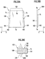
- FIGS. 30A to 30C are a plan view and a side view illustrating a tumble plate 100r of the presently filed embodiment, and a schematic enlarged view of one of side edge portions Tc.
- the tumble plate 100r For the cylinder head 10 as a cast product after completing the casting, it is important for the tumble plate 100r to have no looseness inside the cast product. This is because when used as an engine, the presence of looseness of the tumble plate 100r results in disturbance in tumble flow and causes noises and vibrations. Although the presence of the tumble plate 100, whose side edges Tc are fused to the cylinder head 100, enables looseness of the tumble plate 100r to be avoided, it is conceivable for a fatigue strength of the tumble plate 100r to be adversely affected and there is a need for realizing a structure except one in which the both side edges Tc are fused to the cylinder head 10.
- the tumble plate is formed of a press-formed product, there are probabilities where lubricating oil films or other contaminants resulting from press forming adhere onto the both side edges Tc, and such surface contaminants cause factors for facilitating a clearance between the both side edges Tc and a wall portion of the cylinder head 10. This results in the occurrence of looseness of the tumble plate along a longitudinal direction and a vertical direction, resulting in the occurrence of clearance in the order of approximately 1/10mm.
- the tumble plate 100r has a substantially square shape and is comprised of the both side edges Tc that are cast in by molten metal in cast molding the cylinder head 10, the intake-side distal end Tb that is continuous with the both side edges Tc and located upstream of intake air flow in the intake port 14, and the cylinder-side distal end Ta that is continuous with the both side edges Tc and located downstream of intake air flow in the intake port 14.
- the tumble plate 100r differs from the seventh embodiment in that surface treatment is conducted on the tumble plate 100r at the both side edges Tc to be cast in by molten metal to cause the both side edges Tc to be finished in a coarser roughness than a coarse surface of the partitioning section 103 by which the intake port 14 is partitioned.
- Other structure is similar to the seventh embodiment.
- the coarse surface treatment is conducted on the side end faces 101 of the end faces 102 facing in thickness direction of the both side edges Tc.
- an intake-port forming sand core 200r in which the tumble plate 100r is preliminarily set is also referred to as a "port core 200r" and a region that is treated in a coarse surface is also referred to as a "coarse surface section”.
- the tumble plate 100r may be preferably made of material such as aluminum alloy.
- the tumble plate 100r may preferably have a thickness of a value equal to or greater than approximately 1.5mm in consideration of a need for precluding thermal deformation occurring during heat treatment of a cast product as the cylinder head 10.
- the presently filed embodiment takes the form of a structure wherein surface treatment is conducted on the both side edges Tc to cause the both side edges Tc to be treated in a rough surface to have coarse surface portions 130, and it is preferable for the both side edges Tc to have coarser surface roughness than that of the partitioning section 103. This is because such a structure prevents disturbance in tumble flow and enables to minimize the occurrence of looseness of the tumble plate 100r.
- examples of such method may include mechanical blasting method and chemical corrosion treatment.
- the blasting method may include sand shot blasting and steel shot blasting and corrosion treatment may include corrosion treatment using sodium hydroxide.
- a manufacturing method of the tumble plate 100r is not particularly limited and in view of simply fabricating products in identical quality at low costs, the tumble plate 100r may be fabricated by press forming. Although there are probabilities where lubricating oil films or other contaminants adhere to the tumble plate 100r on pressing step, the presently filed embodiment allows surface treatment to be conducted on the tumble plate 100r after pressing step, thereby simultaneously removing surface contaminants from the both side edges Tc. With the surface contaminants removed, the use of a pressed product as the tumble plate 100r excludes the factors for facilitating the clearance between the both side edges Tc and the cylinder head 10.
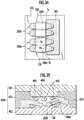
- FIGS. 31A and 31B are views illustrating procedures on which surface treatment is carried out.
- FIG. 31A shows a case where surface treatment is conducted on the both side edges Tc prior to molding the port core 200r
- FIG. 31B shows a case where surface treatment is conducted on the both side edges Tc subsequent to the port core 200r being molded.
- surface treatment may be carried out on the both side edges Tc prior to molding the port core 200r as shown in FIG. 31A and may be carried out subsequent to the port core 200r being molded.
- surface treatment may be preferably conducted by setting a masking 131 on the partitioning section 103. This is because no minute surface roughness, i.e., a smoothness of the partitioning section 103 is deteriorated to prevent the occurrence of disturbance in tumble flow while permitting only the both side edges Tc, serving as the cast-in portions, to have enlarged roughness, enabling to minimize the occurrence of looseness of the tumble plate 100r.
- the masking 131 may be constituted of a masking material 132 or core sand 210 by which the port core 200r is formed.
- the partitioning section 130 is masked with the masking material 132 as the masking 131, thereby enabling surface treatment to be carried out only on the both side edges Tc. Locating the masking material 132 on the partitioning section 103 and carrying out shot blasting with the both side edges Tc being exposed enables the both side edges Tc to have coarse surface roughness while ensuring the partitioning section 103 to have a surface roughness at a low degree.
- the port core 200r is molded as shown in the lowest stage in FIG. 31A .
- the masking 131 is constituted by core sand 210 per se by which the port core 200 is molded. That is, as shown in an upper stage and a middle stage, the partitioning section 103 is masked by core sand 210 serving as the masking material 131, enabling surface treatment to be conducted only for the both side edges Tc.
- the both sided edges Tc are enabled to have enlarged surface roughness while permitting the partitioning section 103 to have a low surface roughness.
- a volume of corrosion liquid to be used in surface treatment can be saved and, in addition, corrosion reaction is facilitated due to residual heat resulting from the cast molding of the port core 200, providing an advantage of shortening a time interval required for surface treatment.
- FIGS. 32A and 32B are a schematic plan view and a schematic side view illustrating the port core 200r in which the tumble plate 100r is preliminarily set.
- FIG. 33 is schematic cross sectional view illustrating a mold 300r for molding the port core 200r
- FIG. 34 is a plan view illustrating a condition where the mold 300r for molding the port core 200r is cut away to expose the tumble plate 100r.
- the mold 300 for molding the port core 200r is also referred to as a "core mold 300r".
- the core mold 300r is used, thereby molding the port core 200r as shown in FIGS. 32A and 32B .
- the port core 200r is set in a casting mold 400r (see FIG. 35 ) by which the cylinder head 10 is cast, thereby forming the intake port 14 of the cylinder head 10.
- the above-described tumble plate 100r is preliminarily set in the port core 200r such that the both side edges Tc, which have the coarse surface portions 130, of the tumble plate 100r is preliminarily set in the port core 200r such that the both side edges Tc protrude outward to be cast in by molten metal.
- the both side edges Tc, protruding outward, of the tumble plate 100r serve as portions to allow the both side edges Tc, which are cast in by molten metal, to be reliably held.
- the cast-in widths of the tumble plate 100r and the cast-in widths may preferably lie in a value of approximately 2mm.
- the tumble plate 100r preliminarily set in the core mold 300r, core sand is blown into a mold cavity, thereby forming the port core 200r.
- the tumble plate 100r is positioned in a manner not to cause displacement in the core mold 200r and is set on a rest formed on a mold parting surface of the core mold 300r. That is, the tumble plate 100r is retained under a condition where it is placed in a circumferential edge of the mold cavity.
- Separating the mold segments, such as the core-forming upper half 301 and the lower half mold 302, in a separating direction as shown by an arrow S in FIG. 33 allows the port core 200r, formed in the core mold 300r, to be taken out from the core mold 300r.
- FIG. 35 is a cross sectional view illustrating a condition where the port core 200r is set in the casting mold 400r by which the cylinder head 10 is cast molded.
- the port core 200r is set in the casting mold 400r for forming the cylinder head 10. Under such a condition, pouring molten metal, such as aluminum alloy, into the mold cavity 400r through the in-gate (not shown) allows the both side edges Tc of the tumble plate 100r to be progressively cast in whereupon with molten metal solidified, a whole of the both side edges Tc is fixed.
- molten metal such as aluminum alloy
- the cores such as the port core 200 are removed, thereby obtaining the cylinder head 10 as a cast product.
- FIG. 36A is a graph plotting results of surface treatment, by which the both side edges Tc are surface treated, for illustrating surface roughness Ra ( ⁇ m) resulting from sand shot blasting and corrosion using sodium hydroxide in comparison with a surface roughness on non-treatment, i.e., with surface roughness Ra ( ⁇ m) of a press-formed product
- FIG. 36B is a graph illustrating looseness generating rate g (%) of the tumble plate 100r with the surface treatment is carried out by sand shot blasting and corrosion, using sodium hydroxide, in comparison with a surface roughness on non-treatment, i.e., with looseness generating rate g (%) of the press-formed product with non-treatment.
- FIG. 36A is a graph plotting results of surface treatment, by which the both side edges Tc are surface treated, for illustrating surface roughness Ra ( ⁇ m) resulting from sand shot blasting and corrosion using sodium hydroxide in comparison with a surface roughness on non-treatment,
- the surface roughness Ra is indicated in an arithmetic average roughness.
- TR1 designates a result of non-treatment with the pressed surface remaining unchanged
- TR2 a result of treatment with steel shot blasting
- TR3 a result of treatment with sand shot blasting
- TR4 a result of corrosion treatment with sodium hydroxide.
- the surface roughness varies depending upon the treatment methods and it is clear that steel shot blasting TR2 is an effective treatment for providing coarse surface roughness.
- the looseness generating rate of the tumble plate 100r depends on the surface roughness of the both side edges Tc, and any one of surface treatments TR2 to Tr4 is effective to remarkably reduce looseness as compared to non-treatment TR1. Although it is understood that the coarser the surface roughness, the more effective to prevent looseness of the tumble plate 100r, with surface treatment conducted by sand shot blasting, no generation of looseness was found.
- the surface treatment may be conducted only on partial regions of the side edges Tc at positions corresponding to the specific range. Furthermore, with the whole of the side edges Tc treated in a coarse surface, the partial regions corresponding to the specific range may be treated in a coarser surface.
- a surface treatment time interval may be varied along the longitudinal direction, or a diameter of shot materials, the amount of shot material to be applied and a concentration of corrosion liquid to be applied may be varied along the longitudinal direction.
- the surface roughness may be possible to adopt any of technique of providing variation between two surface roughness stages, technique of providing stepwise variation in more than three surface roughness stages and technique of continuously varying the surface roughness.
- FIGS. 37A and 37B are a schematic plan view and a schematic side view illustrating a port core 200s in which a tumble plate 100s of the presently filed embodiment is preliminarily set.
- the tumble plate 100s of the presently filed embodiment differs from the seventeenth embodiment in that the both side edges Tc further includes the promoter portions 133, for promoting the solidification of molten metal, whose surfaces are made coarse.
- Other structure is similar to the seventeenth embodiment.
- the locating position of the cylinder-side distal end Ta of the tumble plate 100s serves as an important position because of intensive influence on a generating status of tumbles flow.
- the presently filed embodiment takes the form of a structure wherein, for the cylinder head 10 to be cast, the locating position of the cylinder-side distal end Ta of the tumble plate 100s is fixed while the locating position of the intake-side distal end Tb is made relatively free. Even with the tumble plate 100s subjected to thermal affects during the pouring of molten metal, the thermal affects can be absorbed at the intake-side distal end Tb.
- the promoter portions 133 are provided in limited partial regions of the side end faces 101 on the both side edges Tc and with the presently filed embodiment, such partial regions are made closer to the cylinder-side distal end Ta.
- the promoter portions 133 are comprised of concave portions 134 formed on the respective side end faces 101 on the both side edges Tc.
- the concave portions 134 have respective inner side surfaces, which are surface treated to form coarse surface portions 130, respectively, and the concave portions 134 are shown in respective semi-circular arc shapes in the illustrated example.
- a size, the number of pieces, locating positions and locating densities of the respective indent configurations may be altered in consideration of a locating precision required to the tumble plate 100s and the amount of thermal expansion of the tumble plate 100s.
- the partial regions in which the promoter portions 133 are provided are also referred to as the solidification promoter section "a" and the other region with no provision of the promoter portions 133 is also referred to as the "non-located portion b".
- the promoter portions 133 serve as a key to regulate the locating position of the tumble plate 100s with respect to the intake port 14 by promoting the solidification of molten metal in the vicinity of the partial regions (solidification promoter section "a"), in which the promoter portions 133 are provided, further than the solidification of molten metal in the vicinity of the other region (non-located section "b" as f).
- the solidification promoter section "a" closer to the cylinder-side distal end Ta of the both side edges Tc, has a larger area with molten metal than that of the non-treated section "b" due to the presence of the concave portions 134. Consequently, when the both side edges Tc of the tumble plate 100s are cast in, molten metal in the vicinity of the solidification promoter section "a” is relatively quenched as compared to molten metal in the vicinity of the non-located section "b", thereby promoting the solidification of molten metal.
- the presence of the concave portions 134 causes an increase in flow resistance occurring when molten metal flows and molten metal in the vicinity of the solidification promoter section "a" is apt to relatively stay as compared to molten metal in the vicinity of the non-located section "b", thereby promoting the solidification of molten metal.
- the tumble plate 100s is hard to move, thereby preventing the tumble plate 100s from being displaced. That is, the regions closer to the cylinder-side distal end Ta of the both sides edges Tc are fixed faster than the other region closer to the intake-side distal end Tb, enabling to prevent the positional displacement of the cylinder-side distal end Ta with respect to the intake port 14.
- the solidification promoter section "a” is previously fixed as set forth above, and the non-located section “b” is fixed relatively slower than the solidification promoter section "a". For this reason, it becomes possible to limit or control a direction, in which the tumble plate 100s thermally expands due to heat of molten metal, to one direction in which molten metal is directed from the solidification section "a", where molten metal begins to be solidified, toward the non-located section "b” where molten metal still remains un-solidified.
- the tumble plate 100s since the tumble plate 100s has the regions, closer to the cylinder-side distal end Ta, which is fixed faster, it becomes possible for the direction in which the tumble plate 100s thermally expands to a direction directed to the intake-side distal end Tb. Since the thermal expansion of the tumble plate 100s is concentrated at the intake-side distal end Tb where it is apt to expand, no pressure is applied to the port core 200s by the cylinder-side distal end Ta. Consequently, no probabilities occur for cracks or damages to takes place in an important region for forming the shape of the intake port 14.
- the intake side distal end Tb pressurizes the port core 200s and cracks, which would occur in the port core 200s, can be guided to or induced to the core print. That is, burrs resulting from the cracks in the port core 200s do not occur in an inside of the cylinder head 14 as a cast product after completing the cast molding but takes place in the product-profile outside region. Accordingly, subsequent deburring work can be easily carried out.
- the tumble plate 100s can be precisely cast in with the cylinder-side distal end Ta kept in an important position.
- the locating precision of the intake side distal end Tb of the tumble plate 100s it is probable for the locating precision of the intake side distal end Tb of the tumble plate 100s to be increased in need.
- locating the promoter portions 133 for promoting the solidification of molten metal, in regions closer to the intake-side distal end Tb enables a locating precision of the intake-side distal end Tb to be increased.
- the promoter portions 133 may be located in the end faces 102, facing in the thickness direction, of the both side edges Tc.
- the promoter portions 133 may take the form of suitable structures and shapes as far as the solidification of molten metal is promoted and may include convex portions, concave and convex portions and through-bores.
Claims (17)
- Trennplatte (100, 100a bis 100q, 1005) für eine Einlassöffnung (14) eines durch Formgießen herzustellenden Zylinderkopfes (10), die vor dem Formgießen in einen Sandkern (200, 200a bis 200g, 2008) vorläufig eingesetzt wird, der aufgebracht wird, um die Einlassöffnung zu bilden, und dann gegossen wird, wenn das Formgießen durchgeführt wird, um so die Einlassöffnung in eine Mehrzahl von Öffnungen (14u, 14d) zu trennen, umfassend:- ein einlassseitiges distales Ende (Tb);- ein zylinderseitiges distales Ende (Ta);- ein Paar Seitenkanten (Tc), die mit dem einlassseitigen distalen Ende und dem zylinderseitigen distalen Ende fortlaufend sind und durch eine Metallschmelze gegossen werden sollen, wenn ein Formgießen durchgeführt wird, wobei jedes Paar der Seitenkanten Endflächen (102) aufweist, die einer Dickenrichtung (2) zugewandt sind, und eine Seitenendfläche (101) mit den Endflächen fortlaufend ist; und- gekennzeichnet durch- einen Unterstützungsabschnitt (110, 120), der zumindest an der Seitenendfläche oder den Endflächen von jedem Paar der Seitenkanten vorgesehen ist, wobei der Unterstützungsabschnitt (110, 120) einen vergrößerten Kontaktbereich mit der Metallschmelze aufweist, um eine Verfestigung der Metallschmelze zu unterstützen.
- Trennplatte nach Anspruch 1, wobei der Unterstützungsabschnitt (110, 120) an einem Teilbereich der Seitenendfläche (101) vorgesehen ist.
- Trennplatte nach Anspruch 2, wobei der Unterstützungsabschnitt (110, 120) näher am zylinderseitigen distalen Ende (Ta) liegt.
- Trennplatte nach Anspruch 2, wobei der Unterstützungsabschnitt (110, 120) näher am einlassseitigen distalen Ende (Tb) liegt.
- Trennplatte nach einem der Ansprüche 1 bis 4, wobei der Unterstützungsabschnitt (110, 120) zumindest einen der konkaven Abschnitte (111 bis 113, 124, 127), der konvexen Abschnitte (121 bis 123), der konkaven und konvexen Abschnitte (125) oder der Durchgangsbohrungsabschnitte (126) umfasst.
- Trennplatte nach einem der Ansprüche 1 bis 5, wobei der Unterstützungsabschnitt (110, 120) eine Eingussbreite (L2) aufweist, die größer ist als eine Eingussbreite (L1) eines verbleibenden Abschnitts von jedem Paar der Seitenkanten (Tc).
- Trennplatte nach einem der Ansprüche 1 bis 6, wobei der Unterstützungsabschnitt (110, 120) über die gesamten Bereiche der Seitenendfläche (101) vorgesehen ist.
- Trennplatte nach Anspruch 7, wobei der Unterstützungsabschnitt (110, 120) eingerichtet ist, um ein Ausmaß zu variieren, mit dem die Verfestigung der Metallschmelze entlang einer Längsrichtung (y) der Seitenendfläche (101) unterstützt wird.
- Trennplatte nach Anspruch 1, wobei der Unterstützungsabschnitt (110, 120) an der Seitenendfläche (101) und den Endflächen (102) der Dickenrichtung (2) vorgesehen ist.
- Zylinderkopf (10), der angepasst ist, um durch Formgießen hergestellt zu werden, umfassend:- eine Zylinderbohrung (13);- eine Einlassöffnung (14), die mit der Zylinderbohrung verbunden ist; und- eine Trennplatte (100, 100a bis 100q, 1005), die vor dem Formgießen in einen Sandkern (200, 200a bis 200g, 2008) vorläufig eingesetzt wird, der aufgebracht wird, um die Einlassöffnung zu bilden, und dann gegossen wird, wenn das Formgießen durchgeführt wird, um so die Einlassöffnung in eine Mehrzahl von Öffnungen (14u, 14d) zu trennen, wobei die Trennplatte versehen ist mit:- einem einlassseitigen distalen Ende (Tb);- einem zylinderseitigen distalen Ende (Ta);- einem Paar Seitenkanten (Tc), die mit dem einlassseitigen distalen Ende und dem zylinderseitigen distalen Ende fortlaufend sind und durch eine Metallschmelze gegossen werden sollen, wenn ein Formgießen durchgeführt wird, wobei jedes Paar der Seitenkanten Endflächen (102) aufweist, die einer Dickenrichtung (2) zugewandt sind, und eine Seitenendfläche (101) mit den Endflächen fortlaufend ist; und- gekennzeichnet ist durch einen Unterstützungsabschnitt (110, 120), der zumindest an der Seitenendfläche oder den Endflächen von jedem Paar der Seitenkanten vorgesehen ist, wobei der Unterstützungsabschnitt (110, 120) einen vergrößerten Kontaktbereich mit der Metallschmelze aufweist, um eine Verfestigung der Metallschmelze zu unterstützen.
- Zylinderkopf nach Anspruch 10, wobei das zylinderseitige distale Ende (Ta) der Trennplatte (100, 100a bis 100q, 1008) die Verfestigung der Metallschmelze am Unterstützungsabschnitt unterstützt, um in eine Position ohne Beeinträchtigung eines Kraftstoffeinspritzbereichs (21) oder eines Ventilbetätigungsbereichs (22) gebracht zu werden.
- Verfahren zur Herstellung eines Zylinderkopfes (10) mit einer Trennplatte (100, 100a bis 100g, 1008) für eine Einlassöffnung (14), umfassend:- Vorbereiten einer Trennplatte, die ein einlassseitiges distales Ende (Tb), ein zylinderseitiges distales Ende (Ta) und ein Paar Seitenkanten (Tc) umfasst, die mit dem einlassseitigen distalen Ende und dem zylinderseitigen distalen Ende fortlaufend sind, und das zylinderseitige distale Ende durch eine Metallschmelze gegossen werden soll, wenn ein Formgießen durchgeführt wird;- Einsetzen der Trennplatte in einen Sandkern (200, 200a bis 200g, 2005), der aufgebracht wird, um eine Einlassöffnung zu bilden, so dass jedes Paar der Seitenkanten nach außen freiliegt;- Zuführen der Metallschmelze auf jedes Paar der Seitenkanten der Trennplatte;- Verfestigen der Metallschmelze; und- Entfernen des Sandkerns,- dadurch gekennzeichnet, dass bei der Vorbereitung der Trennplatte die Trennplatte mit einem Unterstützungsabschnitt (110, 120) versehen ist, der an zumindest einer der in Dickenrichtung (2) zugewandten Endflächen (102) oder einer Seitenendfläche (101) vorgesehen ist, die mit den Endflächen von jedem Paar der Seitenkanten fortlaufend sind, um die Verfestigung der Metallschmelze zu unterstützen, wobei der Unterstützungsabschnitt (110, 120) einen vergrößerte Kontaktbereich mit der Metallschmelze aufweist, wodurch die Metallschmelze beim Unterstützen der Verfestigung der Metallschmelze mit dem Unterstützungsabschnitt verfestigt wird.
- Trennplatte (100r, 1003) für eine Einlassöffnung (14) eines Zylinderkopfes (10), die angepasst ist, um durch Formgießen hergestellt zu werden, die vor dem Formgießen in einen Sandkern (200r, 200s) vorläufig eingesetzt wird, der aufgebracht wird, um die Einlassöffnung zu bilden, und dann gegossen wird, wenn das Formgießen durchgeführt wird, um so die Einlassöffnung in eine Mehrzahl von Öffnungen (14u, 14d) zu trennen, umfassend:- ein einlassseitiges distales Ende (Tb);- ein zylinderseitiges distales Ende (Ta);- ein Paar Seitenkanten (Tc), die mit dem einlassseitigen distalen Ende und dem zylinderseitigen distalen Ende fortlaufend sind und durch eine Metallschmelze gegossen werden sollen, wenn ein Formgießen durchgeführt wird; und gekennzeichnet ist durch- einen oberflächenbehandelten Abschnitt (130), der an jedem Paar der Seitenkanten vorgesehen ist, und der einer Oberflächenbehandlung auf einer groben Oberfläche unterzogen wird, um eine gröbere Oberflächenrauheit als eine Oberflächenrauheit eines Trennabschnitts (103) aufzuweisen, durch den eine Einlassöffnung getrennt wird.
- Trennplatte nach Anspruch 13, wobei die Oberflächenbehandlung ausgeführt wird, während der Trennabschnitt (103) mit einem Abdeckmaterial (132) oder einem Sandkern (2008, 200r) abgedeckt ist.
- Trennplatte nach Anspruch 13 oder 14, die ferner einen Unterstützungsabschnitt (110) aufweist, der an jedem Paar der Seitenkanten (Tc) vorgesehen ist, um eine Verfestigung der Metallschmelze zu unterstützen, wobei der Unterstützungsabschnitt auf einer groben Oberfläche behandelt wird, um eine gröbere Oberflächenrauheit als die Oberflächenrauheit des Trennabschnitts (103) aufzuweisen.
- Zylinderkopf (10), der angepasst ist, um durch Formgießen hergestellt zu werden, umfassend:- eine Zylinderbohrung (13);- eine Einlassöffnung (14), die mit der Zylinderbohrung verbunden ist; und- eine Trennplatte (100r, 1008), die vor dem Formgießen in einen Sandkern (200r, 2008) vorläufig eingesetzt wird, der aufgebracht wird, um die Einlassöffnung zu bilden, und dann gegossen wird, wenn das Formgießen durchgeführt wird, um so die Einlassöffnung in eine Mehrzahl von Öffnungen (14u, 14d) zu trennen, wobei die Trennplatte versehen ist mit:- einem einlassseitigen distalen Ende (Tb);- einem zylinderseitigen distalen Ende (Ta);- einem Paar Seitenkanten (Tc), die mit dem einlassseitigen distalen Ende und dem zylinderseitigen distalen Ende fortlaufend sind, und durch eine Metallschmelze gegossen werden sollen, wenn ein Formgießen durchgeführt wird; und gekennzeichnet durch- einen oberflächenbehandelten Abschnitt (130), der an jedem Paar der Seitenkanten vorgesehen ist, und der einer Oberflächenbehandlung auf einer groben Oberfläche unterzogen wird, um eine gröbere Oberflächenrauheit als eine Oberflächenrauheit eines Trennabschnitts (103) aufzuweisen, durch den eine Einlassöffnung getrennt wird.
- Verfahren zum Herstellen eines Zylinderkopfs (10) mit einer Trennplatte (100r, 100s) für eine Einlassöffnung, umfassend:- Vorbereiten einer Trennplatte, die ein einlassseitiges distales Ende (Tb), ein zylinderseitiges distales Ende (Ta) und ein Paar Seitenkanten (Tc) umfasst, die mit dem einlassseitigen distalen Ende und dem zylinderseitigen distalen Ende fortlaufend sind, und durch eine Metallschmelze gegossen werden sollen, wenn ein Formgießen durchgeführt wird, durch das eine Einlassöffnung getrennt wird;- Einsetzen der Trennplatte in einen Sandkern (200r, 2003), um die Einlassöffnung zu bilden, so dass jedes Paar der Seitenkanten nach außen freiliegt;- Zuführen der Metallschmelze auf jedes Paar der Seitenkanten der Trennplatte;- Verfestigen der Metallschmelze, während ein Eingießen des oberflächenbehandelten Abschnitts bewirkt wird; und- Entfernen des Sandkerns,- dadurch gekennzeichnet, dass bei der Vorbereitung der Trennplatte die Trennplatte mit einem oberflächenbehandelten Abschnitt (130) versehen wird, der an jedem Paar der Seitenkanten vorgesehen ist, und einer Oberflächenbehandlung auf einer groben Oberfläche unterzogen wird, um eine gröbere Oberflächenrauheit als eine Oberflächenrauheit eines Trennabschnitts (103) aufzuweisen, wodurch die Metallschmelze verfestigt wird, während ein Eingießen des oberflächenbehandelten Abschnitts bewirkt wird.
Applications Claiming Priority (6)
| Application Number | Priority Date | Filing Date | Title |
|---|---|---|---|
| JP2003359934A JP4226435B2 (ja) | 2003-10-20 | 2003-10-20 | 吸気ポート用の仕切り板、吸気ポート成形用砂中子およびシリンダヘッド |
| JP2003359940A JP2005120997A (ja) | 2003-10-20 | 2003-10-20 | 吸気ポート用の仕切り板、吸気ポート成形用砂中子およびシリンダヘッド |
| JP2003359931 | 2003-10-20 | ||
| JP2003359940 | 2003-10-20 | ||
| JP2003359934 | 2003-10-20 | ||
| JP2003359931A JP4206025B2 (ja) | 2003-10-20 | 2003-10-20 | 吸気ポート用の仕切り板、吸気ポート成形用砂中子およびシリンダヘッド |
Publications (2)
| Publication Number | Publication Date |
|---|---|
| EP1548263A1 EP1548263A1 (de) | 2005-06-29 |
| EP1548263B1 true EP1548263B1 (de) | 2019-12-11 |
Family
ID=34557006
Family Applications (1)
| Application Number | Title | Priority Date | Filing Date |
|---|---|---|---|
| EP04024658.9A Expired - Fee Related EP1548263B1 (de) | 2003-10-20 | 2004-10-15 | Trennblech für einlasskanal und sandkern zur formung des einlasskanals und zylinderkopf |
Country Status (3)
| Country | Link |
|---|---|
| US (1) | US7032560B2 (de) |
| EP (1) | EP1548263B1 (de) |
| KR (1) | KR100686532B1 (de) |
Families Citing this family (18)
| Publication number | Priority date | Publication date | Assignee | Title |
|---|---|---|---|---|
| DE102004037279B4 (de) * | 2004-07-31 | 2009-02-26 | Audi Ag | Gasansaugung einer Brennkraftmaschine mit mindestens einem Strömungskanal |
| JP4400503B2 (ja) * | 2005-04-19 | 2010-01-20 | 日産自動車株式会社 | 吸気ポート用の仕切り板、吸気ポート成形用砂中子およびシリンダヘッド |
| US7802555B2 (en) * | 2008-03-18 | 2010-09-28 | Yamaha Hatsudoki Kabushiki Kaisha | Intake control device for an engine |
| US8677616B2 (en) * | 2010-02-09 | 2014-03-25 | Pratt & Whitney Canada Corp. | Method for production of electrical conductors |
| JP5988236B2 (ja) * | 2011-08-30 | 2016-09-07 | 俊彦 山本 | エンジンの吸気装置 |
| US8997721B2 (en) * | 2011-08-30 | 2015-04-07 | Toshihiko Yamamoto | Intake apparatus of engine |
| JP6327180B2 (ja) * | 2015-03-12 | 2018-05-23 | トヨタ自動車株式会社 | 内燃機関 |
| KR20160134905A (ko) * | 2015-05-13 | 2016-11-24 | 현대자동차주식회사 | 엔진의 공기 유동성 개선 장치 |
| JP6288116B2 (ja) | 2016-01-21 | 2018-03-07 | トヨタ自動車株式会社 | シリンダヘッドの製造方法 |
| JP6384493B2 (ja) * | 2016-01-21 | 2018-09-05 | トヨタ自動車株式会社 | シリンダヘッドの製造方法 |
| US9664151B1 (en) * | 2016-04-08 | 2017-05-30 | Kao-Shan Lin | Air admission device for combustion equipment |
| JP7027862B2 (ja) * | 2017-12-14 | 2022-03-02 | トヨタ紡織株式会社 | 吸気管の接続構造 |
| JP6630748B2 (ja) * | 2018-01-05 | 2020-01-15 | 株式会社Subaru | エンジン |
| CN108952990A (zh) * | 2018-06-27 | 2018-12-07 | 山西中条山机电设备有限公司 | 一种高强度合金铸铁气缸盖及其生产工艺 |
| CN109973223B (zh) * | 2019-04-01 | 2020-06-02 | 中国航发湖南动力机械研究所 | 粒子分离器的加工方法、粒子分离器及航空涡轴发动机 |
| JP2021188588A (ja) * | 2020-06-03 | 2021-12-13 | 株式会社Subaru | エンジン |
| KR102337689B1 (ko) | 2021-05-14 | 2021-12-09 | 김기영 | 샌드코어 로봇시스템 그리퍼유닛 |
| KR102316399B1 (ko) | 2021-05-27 | 2021-10-22 | 김기영 | 샌드코어 조립 자동화 시스템 |
Family Cites Families (5)
| Publication number | Priority date | Publication date | Assignee | Title |
|---|---|---|---|---|
| DE9319545U1 (de) * | 1993-12-20 | 1995-04-20 | Fev Motorentech Gmbh & Co Kg | Fremdgezündeter Kolbenmotor mit richtungsänderbarer Einströmung des Kraftstoff-Luft-Gemisches |
| DE19803867A1 (de) * | 1998-01-31 | 1999-08-05 | Volkswagen Ag | Verfahren zum Herstellen eines Zylinderkopfes einer Brennkraftmaschine |
| DE19960626A1 (de) | 1999-12-16 | 2001-06-21 | Fev Motorentech Gmbh | Kolbenbrennkraftmaschine mit unterteiltem Gaseinlaßkanal |
| AU761892B2 (en) * | 2000-12-27 | 2003-06-12 | Hyundai Motor Company | Variable tumble flow-generating device of engine and manufacturing method of variable tumble flow-generating intake port |
| JP3695401B2 (ja) * | 2002-02-13 | 2005-09-14 | 日産自動車株式会社 | 内燃機関の吸気装置 |
-
2004
- 2004-10-15 EP EP04024658.9A patent/EP1548263B1/de not_active Expired - Fee Related
- 2004-10-19 US US10/967,144 patent/US7032560B2/en active Active
- 2004-10-20 KR KR1020040084093A patent/KR100686532B1/ko active IP Right Grant
Non-Patent Citations (1)
| Title |
|---|
| None * |
Also Published As
| Publication number | Publication date |
|---|---|
| EP1548263A1 (de) | 2005-06-29 |
| KR100686532B1 (ko) | 2007-02-23 |
| KR20050037980A (ko) | 2005-04-25 |
| US20050081821A1 (en) | 2005-04-21 |
| US7032560B2 (en) | 2006-04-25 |
Similar Documents
| Publication | Publication Date | Title |
|---|---|---|
| EP1548263B1 (de) | Trennblech für einlasskanal und sandkern zur formung des einlasskanals und zylinderkopf | |
| JP4400503B2 (ja) | 吸気ポート用の仕切り板、吸気ポート成形用砂中子およびシリンダヘッド | |
| EP1239135A2 (de) | Zylinderkopfkühlung und Verfahren zur Herstellung | |
| US7100560B2 (en) | Partition plate for intake port, intake port molding sand core and cylinder head | |
| US7032559B2 (en) | Cast-in object plate member, partition plate for intake port, intake-port forming sand core and cylinder head | |
| JP3417331B2 (ja) | シリンダヘッド及びその製造方法 | |
| JP4185822B2 (ja) | 内燃エンジン用シリンダの製造方法 | |
| EP1526270B1 (de) | Methode zum Verfahren eines Zylinderkopfes | |
| JP6117575B2 (ja) | 鋳造用金型装置 | |
| JP4226435B2 (ja) | 吸気ポート用の仕切り板、吸気ポート成形用砂中子およびシリンダヘッド | |
| JP4206025B2 (ja) | 吸気ポート用の仕切り板、吸気ポート成形用砂中子およびシリンダヘッド | |
| JP4284149B2 (ja) | 砂中子造型装置およびシリンダヘッド | |
| JPH0263645A (ja) | シリンダーヘッドの鋳造方法 | |
| JP4330423B2 (ja) | 鋳造装置 | |
| JP2005120997A (ja) | 吸気ポート用の仕切り板、吸気ポート成形用砂中子およびシリンダヘッド | |
| JP4284148B2 (ja) | 砂中子造型装置 | |
| JP2002266692A (ja) | エンジン構造物及びその製造方法 | |
| JPH084583A (ja) | シリンダブロックの構造及び製造方法 |
Legal Events
| Date | Code | Title | Description |
|---|---|---|---|
| PUAI | Public reference made under article 153(3) epc to a published international application that has entered the european phase |
Free format text: ORIGINAL CODE: 0009012 |
|
| 17P | Request for examination filed |
Effective date: 20041015 |
|
| AK | Designated contracting states |
Kind code of ref document: A1 Designated state(s): AT BE BG CH CY CZ DE DK EE ES FI FR GB GR HU IE IT LI LU MC NL PL PT RO SE SI SK TR |
|
| AX | Request for extension of the european patent |
Extension state: AL HR LT LV MK |
|
| AKX | Designation fees paid |
Designated state(s): DE FR GB |
|
| 17Q | First examination report despatched |
Effective date: 20060807 |
|
| RAP1 | Party data changed (applicant data changed or rights of an application transferred) |
Owner name: AICHI MACHINE INDUSTRY CO., LTD. Owner name: NISSAN MOTOR CO., LTD. |
|
| GRAP | Despatch of communication of intention to grant a patent |
Free format text: ORIGINAL CODE: EPIDOSNIGR1 |
|
| INTG | Intention to grant announced |
Effective date: 20190725 |
|
| GRAS | Grant fee paid |
Free format text: ORIGINAL CODE: EPIDOSNIGR3 |
|
| GRAA | (expected) grant |
Free format text: ORIGINAL CODE: 0009210 |
|
| AK | Designated contracting states |
Kind code of ref document: B1 Designated state(s): DE FR GB |
|
| REG | Reference to a national code |
Ref country code: GB Ref legal event code: FG4D |
|
| REG | Reference to a national code |
Ref country code: DE Ref legal event code: R096 Ref document number: 602004054405 Country of ref document: DE |
|
| REG | Reference to a national code |
Ref country code: DE Ref legal event code: R097 Ref document number: 602004054405 Country of ref document: DE |
|
| PLBE | No opposition filed within time limit |
Free format text: ORIGINAL CODE: 0009261 |
|
| STAA | Information on the status of an ep patent application or granted ep patent |
Free format text: STATUS: NO OPPOSITION FILED WITHIN TIME LIMIT |
|
| PGFP | Annual fee paid to national office [announced via postgrant information from national office to epo] |
Ref country code: FR Payment date: 20200914 Year of fee payment: 17 |
|
| 26N | No opposition filed |
Effective date: 20200914 |
|
| PGFP | Annual fee paid to national office [announced via postgrant information from national office to epo] |
Ref country code: GB Payment date: 20201007 Year of fee payment: 17 Ref country code: DE Payment date: 20200929 Year of fee payment: 17 |
|
| REG | Reference to a national code |
Ref country code: DE Ref legal event code: R119 Ref document number: 602004054405 Country of ref document: DE |
|
| GBPC | Gb: european patent ceased through non-payment of renewal fee |
Effective date: 20211015 |
|
| PG25 | Lapsed in a contracting state [announced via postgrant information from national office to epo] |
Ref country code: GB Free format text: LAPSE BECAUSE OF NON-PAYMENT OF DUE FEES Effective date: 20211015 Ref country code: DE Free format text: LAPSE BECAUSE OF NON-PAYMENT OF DUE FEES Effective date: 20220503 |
|
| PG25 | Lapsed in a contracting state [announced via postgrant information from national office to epo] |
Ref country code: FR Free format text: LAPSE BECAUSE OF NON-PAYMENT OF DUE FEES Effective date: 20211031 |