EP1548140A1 - B enthaltendes edelstahlprodukt und herstellungsverfahren dafür - Google Patents
B enthaltendes edelstahlprodukt und herstellungsverfahren dafür Download PDFInfo
- Publication number
- EP1548140A1 EP1548140A1 EP03795286A EP03795286A EP1548140A1 EP 1548140 A1 EP1548140 A1 EP 1548140A1 EP 03795286 A EP03795286 A EP 03795286A EP 03795286 A EP03795286 A EP 03795286A EP 1548140 A1 EP1548140 A1 EP 1548140A1
- Authority
- EP
- European Patent Office
- Prior art keywords
- stainless steel
- protecting material
- thickness
- bloom
- content
- Prior art date
- Legal status (The legal status is an assumption and is not a legal conclusion. Google has not performed a legal analysis and makes no representation as to the accuracy of the status listed.)
- Granted
Links
Images


Classifications
-
- B—PERFORMING OPERATIONS; TRANSPORTING
- B21—MECHANICAL METAL-WORKING WITHOUT ESSENTIALLY REMOVING MATERIAL; PUNCHING METAL
- B21B—ROLLING OF METAL
- B21B3/00—Rolling materials of special alloys so far as the composition of the alloy requires or permits special rolling methods or sequences ; Rolling of aluminium, copper, zinc or other non-ferrous metals
- B21B3/02—Rolling special iron alloys, e.g. stainless steel
-
- B—PERFORMING OPERATIONS; TRANSPORTING
- B23—MACHINE TOOLS; METAL-WORKING NOT OTHERWISE PROVIDED FOR
- B23K—SOLDERING OR UNSOLDERING; WELDING; CLADDING OR PLATING BY SOLDERING OR WELDING; CUTTING BY APPLYING HEAT LOCALLY, e.g. FLAME CUTTING; WORKING BY LASER BEAM
- B23K35/00—Rods, electrodes, materials, or media, for use in soldering, welding, or cutting
- B23K35/22—Rods, electrodes, materials, or media, for use in soldering, welding, or cutting characterised by the composition or nature of the material
- B23K35/24—Selection of soldering or welding materials proper
- B23K35/30—Selection of soldering or welding materials proper with the principal constituent melting at less than 1550 degrees C
- B23K35/3053—Fe as the principal constituent
- B23K35/308—Fe as the principal constituent with Cr as next major constituent
- B23K35/3086—Fe as the principal constituent with Cr as next major constituent containing Ni or Mn
-
- C—CHEMISTRY; METALLURGY
- C22—METALLURGY; FERROUS OR NON-FERROUS ALLOYS; TREATMENT OF ALLOYS OR NON-FERROUS METALS
- C22C—ALLOYS
- C22C38/00—Ferrous alloys, e.g. steel alloys
- C22C38/001—Ferrous alloys, e.g. steel alloys containing N
-
- C—CHEMISTRY; METALLURGY
- C22—METALLURGY; FERROUS OR NON-FERROUS ALLOYS; TREATMENT OF ALLOYS OR NON-FERROUS METALS
- C22C—ALLOYS
- C22C38/00—Ferrous alloys, e.g. steel alloys
- C22C38/02—Ferrous alloys, e.g. steel alloys containing silicon
-
- C—CHEMISTRY; METALLURGY
- C22—METALLURGY; FERROUS OR NON-FERROUS ALLOYS; TREATMENT OF ALLOYS OR NON-FERROUS METALS
- C22C—ALLOYS
- C22C38/00—Ferrous alloys, e.g. steel alloys
- C22C38/04—Ferrous alloys, e.g. steel alloys containing manganese
-
- C—CHEMISTRY; METALLURGY
- C22—METALLURGY; FERROUS OR NON-FERROUS ALLOYS; TREATMENT OF ALLOYS OR NON-FERROUS METALS
- C22C—ALLOYS
- C22C38/00—Ferrous alloys, e.g. steel alloys
- C22C38/06—Ferrous alloys, e.g. steel alloys containing aluminium
-
- C—CHEMISTRY; METALLURGY
- C22—METALLURGY; FERROUS OR NON-FERROUS ALLOYS; TREATMENT OF ALLOYS OR NON-FERROUS METALS
- C22C—ALLOYS
- C22C38/00—Ferrous alloys, e.g. steel alloys
- C22C38/18—Ferrous alloys, e.g. steel alloys containing chromium
- C22C38/40—Ferrous alloys, e.g. steel alloys containing chromium with nickel
- C22C38/44—Ferrous alloys, e.g. steel alloys containing chromium with nickel with molybdenum or tungsten
-
- C—CHEMISTRY; METALLURGY
- C22—METALLURGY; FERROUS OR NON-FERROUS ALLOYS; TREATMENT OF ALLOYS OR NON-FERROUS METALS
- C22C—ALLOYS
- C22C38/00—Ferrous alloys, e.g. steel alloys
- C22C38/18—Ferrous alloys, e.g. steel alloys containing chromium
- C22C38/40—Ferrous alloys, e.g. steel alloys containing chromium with nickel
- C22C38/54—Ferrous alloys, e.g. steel alloys containing chromium with nickel with boron
-
- H—ELECTRICITY
- H01—ELECTRIC ELEMENTS
- H01M—PROCESSES OR MEANS, e.g. BATTERIES, FOR THE DIRECT CONVERSION OF CHEMICAL ENERGY INTO ELECTRICAL ENERGY
- H01M8/00—Fuel cells; Manufacture thereof
- H01M8/02—Details
- H01M8/0202—Collectors; Separators, e.g. bipolar separators; Interconnectors
- H01M8/0204—Non-porous and characterised by the material
- H01M8/0206—Metals or alloys
- H01M8/0208—Alloys
- H01M8/021—Alloys based on iron
-
- B—PERFORMING OPERATIONS; TRANSPORTING
- B21—MECHANICAL METAL-WORKING WITHOUT ESSENTIALLY REMOVING MATERIAL; PUNCHING METAL
- B21B—ROLLING OF METAL
- B21B1/00—Metal-rolling methods or mills for making semi-finished products of solid or profiled cross-section; Sequence of operations in milling trains; Layout of rolling-mill plant, e.g. grouping of stands; Succession of passes or of sectional pass alternations
- B21B1/02—Metal-rolling methods or mills for making semi-finished products of solid or profiled cross-section; Sequence of operations in milling trains; Layout of rolling-mill plant, e.g. grouping of stands; Succession of passes or of sectional pass alternations for rolling heavy work, e.g. ingots, slabs, blooms, or billets, in which the cross-sectional form is unimportant ; Rolling combined with forging or pressing
- B21B1/024—Forging or pressing
-
- B—PERFORMING OPERATIONS; TRANSPORTING
- B21—MECHANICAL METAL-WORKING WITHOUT ESSENTIALLY REMOVING MATERIAL; PUNCHING METAL
- B21B—ROLLING OF METAL
- B21B1/00—Metal-rolling methods or mills for making semi-finished products of solid or profiled cross-section; Sequence of operations in milling trains; Layout of rolling-mill plant, e.g. grouping of stands; Succession of passes or of sectional pass alternations
- B21B1/02—Metal-rolling methods or mills for making semi-finished products of solid or profiled cross-section; Sequence of operations in milling trains; Layout of rolling-mill plant, e.g. grouping of stands; Succession of passes or of sectional pass alternations for rolling heavy work, e.g. ingots, slabs, blooms, or billets, in which the cross-sectional form is unimportant ; Rolling combined with forging or pressing
- B21B1/026—Rolling
-
- B—PERFORMING OPERATIONS; TRANSPORTING
- B21—MECHANICAL METAL-WORKING WITHOUT ESSENTIALLY REMOVING MATERIAL; PUNCHING METAL
- B21B—ROLLING OF METAL
- B21B1/00—Metal-rolling methods or mills for making semi-finished products of solid or profiled cross-section; Sequence of operations in milling trains; Layout of rolling-mill plant, e.g. grouping of stands; Succession of passes or of sectional pass alternations
- B21B1/02—Metal-rolling methods or mills for making semi-finished products of solid or profiled cross-section; Sequence of operations in milling trains; Layout of rolling-mill plant, e.g. grouping of stands; Succession of passes or of sectional pass alternations for rolling heavy work, e.g. ingots, slabs, blooms, or billets, in which the cross-sectional form is unimportant ; Rolling combined with forging or pressing
- B21B2001/022—Blooms or billets
-
- B—PERFORMING OPERATIONS; TRANSPORTING
- B21—MECHANICAL METAL-WORKING WITHOUT ESSENTIALLY REMOVING MATERIAL; PUNCHING METAL
- B21B—ROLLING OF METAL
- B21B1/00—Metal-rolling methods or mills for making semi-finished products of solid or profiled cross-section; Sequence of operations in milling trains; Layout of rolling-mill plant, e.g. grouping of stands; Succession of passes or of sectional pass alternations
- B21B1/02—Metal-rolling methods or mills for making semi-finished products of solid or profiled cross-section; Sequence of operations in milling trains; Layout of rolling-mill plant, e.g. grouping of stands; Succession of passes or of sectional pass alternations for rolling heavy work, e.g. ingots, slabs, blooms, or billets, in which the cross-sectional form is unimportant ; Rolling combined with forging or pressing
- B21B2001/028—Slabs
-
- B—PERFORMING OPERATIONS; TRANSPORTING
- B23—MACHINE TOOLS; METAL-WORKING NOT OTHERWISE PROVIDED FOR
- B23K—SOLDERING OR UNSOLDERING; WELDING; CLADDING OR PLATING BY SOLDERING OR WELDING; CUTTING BY APPLYING HEAT LOCALLY, e.g. FLAME CUTTING; WORKING BY LASER BEAM
- B23K15/00—Electron-beam welding or cutting
-
- B—PERFORMING OPERATIONS; TRANSPORTING
- B23—MACHINE TOOLS; METAL-WORKING NOT OTHERWISE PROVIDED FOR
- B23K—SOLDERING OR UNSOLDERING; WELDING; CLADDING OR PLATING BY SOLDERING OR WELDING; CUTTING BY APPLYING HEAT LOCALLY, e.g. FLAME CUTTING; WORKING BY LASER BEAM
- B23K2103/00—Materials to be soldered, welded or cut
- B23K2103/02—Iron or ferrous alloys
- B23K2103/04—Steel or steel alloys
- B23K2103/05—Stainless steel
-
- Y—GENERAL TAGGING OF NEW TECHNOLOGICAL DEVELOPMENTS; GENERAL TAGGING OF CROSS-SECTIONAL TECHNOLOGIES SPANNING OVER SEVERAL SECTIONS OF THE IPC; TECHNICAL SUBJECTS COVERED BY FORMER USPC CROSS-REFERENCE ART COLLECTIONS [XRACs] AND DIGESTS
- Y02—TECHNOLOGIES OR APPLICATIONS FOR MITIGATION OR ADAPTATION AGAINST CLIMATE CHANGE
- Y02E—REDUCTION OF GREENHOUSE GAS [GHG] EMISSIONS, RELATED TO ENERGY GENERATION, TRANSMISSION OR DISTRIBUTION
- Y02E30/00—Energy generation of nuclear origin
- Y02E30/30—Nuclear fission reactors
-
- Y—GENERAL TAGGING OF NEW TECHNOLOGICAL DEVELOPMENTS; GENERAL TAGGING OF CROSS-SECTIONAL TECHNOLOGIES SPANNING OVER SEVERAL SECTIONS OF THE IPC; TECHNICAL SUBJECTS COVERED BY FORMER USPC CROSS-REFERENCE ART COLLECTIONS [XRACs] AND DIGESTS
- Y02—TECHNOLOGIES OR APPLICATIONS FOR MITIGATION OR ADAPTATION AGAINST CLIMATE CHANGE
- Y02E—REDUCTION OF GREENHOUSE GAS [GHG] EMISSIONS, RELATED TO ENERGY GENERATION, TRANSMISSION OR DISTRIBUTION
- Y02E60/00—Enabling technologies; Technologies with a potential or indirect contribution to GHG emissions mitigation
- Y02E60/30—Hydrogen technology
- Y02E60/50—Fuel cells
-
- Y—GENERAL TAGGING OF NEW TECHNOLOGICAL DEVELOPMENTS; GENERAL TAGGING OF CROSS-SECTIONAL TECHNOLOGIES SPANNING OVER SEVERAL SECTIONS OF THE IPC; TECHNICAL SUBJECTS COVERED BY FORMER USPC CROSS-REFERENCE ART COLLECTIONS [XRACs] AND DIGESTS
- Y02—TECHNOLOGIES OR APPLICATIONS FOR MITIGATION OR ADAPTATION AGAINST CLIMATE CHANGE
- Y02P—CLIMATE CHANGE MITIGATION TECHNOLOGIES IN THE PRODUCTION OR PROCESSING OF GOODS
- Y02P70/00—Climate change mitigation technologies in the production process for final industrial or consumer products
- Y02P70/50—Manufacturing or production processes characterised by the final manufactured product
Definitions
- the present invention relates to a stainless steel slab containing B as well as a stainless steel product containing B for use of a neutron shielding material in equipments regarding nuclear power plants such as a nuclear fuel transport cask, a storage rack of spent nuclear fuel and the like, and further for usage where an addition of B with 0.3% or more into an austenitic stainless steel should enhance the function, for instance, for use of a separator of a fuel cell, and relates to a method for production thereof.
- a stainless steel containing B is applied as a thermal neutron control rod as well as a thermal neutron shielding material by utilizing an excellent thermal neutron absorption effect of boron (B).
- B boron
- Austenitic stainless steels have excellent resistance to corrosion owing to the formed passive film on the surface, and further an addition of B into it improves the electric resistance characteristic, thus enabling to be used for high conductivity electric device requiring further corrosion resistance.
- a separator for fuel cell that generates direct current electric power by utilizing hydrogen and oxygen.
- B boron diffuses from a base metal to the weld metal and forms a mixture therein. Due to this, there is an occasion that cracks generate at the weld portion during rolling, causing rolling trouble and or leading to edge cracking developed from the initiation site of said cracks at the weld portion.
- a hot rolling workpiece material formed by a slab of an austenitic stainless steel containing B of 0.6 - 2.0 mass % and a layer by overlay weld formed at both side edge portions of said slab, a layer by overlay weld comprising a ⁇ ferrite content of 3 - 12 volume %, and a B content of 0.3 mass % or less, and a thickness of 3 mm or more.
- the present invention is intended to solve the above problems in the prior art. Accordingly, it is an object of the present invention to provide a hot rolling method as well as a cold rolling method that enable to make a stainless steel slab containing high B content by rolling down to a predetermined thickness with minimum welding time and without generating any edge cracking nor any crack at weldments, and to provide steel products containing high B content.
- the present invention intends to provide a stainless steel slab containing B that a protecting material is bonded at side portions thereof by high-efficiency electron beam welding, a stainless steel product containing B, and a method for production of a stainless steel product that enables to prevent a workpiece material from generating edge cracking nor cracks at weldments during hot working process.
- the present inventors carried out several investigations to solve the above problems, and obtained following findings described in (a) through (d), which ending up to complete the present invention.
- the present invention is completed based on above findings, and a gist of the present invention is to provide a stainless steel slab containing B, a stainless steel product containing B, and a method for production thereof as described below respectively.
- Fig. 1 is a schematic diagram showing a stainless steel slab containing B.
- the term "stainless steel bloom” in the present invention designates either continuous cast slab, hot forging slab, blooming slab, or cast ingot (steel ingot), which is used as a base metal in Fig. 1.
- the bloom is in a rectangular solid form and is subjected to hot working such as hot rolling or forging so as to be elongated in longitudinal direction.
- the phrase "at least two faces across the bloom from each other, excluding a working plane” is defined to be two faces opposing each other across the bloom among surfaces excluding working planes subjected to rolling, forging or the like.
- rolling it means two longitudinal side end faces, or may include the case which consists of top and tail end face also.
- forging it means two side end faces opposing each other that do not contact with a ram, or the case which may include three or four faces further.
- chamfering is carried out for removing the corners, it may include the chamfered faces also.
- a thickness of a protecting material is meant to a thickness in transverse direction of a protecting material in the plane parallel to a working plane before being bonded to a base metal.
- a total thickness of a bare protecting material and a resultant weld metal within the protecting material is primarily referred.
- Wild metal is defined to as one part of a bonded layer, and to as a metal portion where a base metal along with a protecting material prior to bonding is fused and solidified in bonding process, excluding a heat affected zone (HAZ) which simply causes solid phase transformation.
- HZ heat affected zone
- An insert material is meant to a material inserted or interposed between a stainless steel bloom (base metal) and a protecting material, which is, to be concrete, exemplified by a plate type, a metal foil type, a powder layer or the like.
- the present inventors investigated the method for production of a steel product, wherein a protecting material having a predetermined thickness is bonded onto side end faces of a steel bloom, and rolling etc. can be subsequently applied as an economical method rather than the method to build up a protecting layer by overlay welding onto side end faces of a workpiece material.
- Electron beam welding method is applied for bonding of a protecting material.
- Table 1 shows each chemical composition of steel blooms as base metals and protecting materials in whole.
- a bloom of 200 mm wide x 50 mm thick x 100 mm long in dimension comprising a stainless steel containing B designated as Steel No. M1 in Table 1 was prepared, and a protecting material comprising an austenitic stainless steel (TP304L) designated as Steel No. P1 in Table 1 was welded onto side end faces of said bloom by applying above electron beam welding method, which is referred to as a test block in the end.
- TP304L austenitic stainless steel
- the applied condition of electron beam welding comprised a welding current: 350 mA, a welding speed: 130 mm/min, and a scanning amplitude of electron beam: ⁇ 2 mm.
- a protecting material was ground off, and a thickness in the plane parallel to a working plane, in transverse direction from side end face of a prior base metal block before welding (a bare thickness of a protecting material, excluding weld metal portion), is adjusted within the range of 0 - 10 mm.
- the test block thus constructed was heated at 1180°C for one hour or more, and was subjected to hot rolling with finishing temperature of 600 - 700°C. So as to secure a finishing thickness of a sheet to be 1.0 mm, and to secure a total reduction ratio (initial thickness/finishing thickness (-)) to be 50.0, a hot rolling process in multiple passes was applied by using 2 high mill consisted of work rolls with 350 mm in diameter.
- Bare Thickness of Protecting Material indicates of a protecting material which was not fused even by welding
- Weld Metal Thickness in Protecting Material indicates a thickness of part of a protecting material which was fused by welding.
- Thickness of Protecting Material indicates a total amount of Bare Thickness of Protecting Material and Weld Metal Thickness in Protecting Material, which was converted as Thickness of Protecting Material prior to welding.
- edge cracking was based on visual inspection for side edge portions over whole length after rolling, wherein, when the length of a crack indication is less than 0.1 mm, it is evaluated as "No Crack” indicated by symbol O, while the case when the length of a crack indication is not less than 0.1 mm is judged as "Cracking" indicated by symbol X.
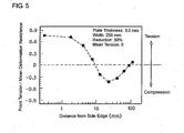
- This test result was acquired by using a test rolling mill that is simulated to a commercial rolling mill on a reduced scale of 1/ 2 through 1/5. Thus, based on this test result, it is necessary to estimate a required thickness of a protecting material for prevention of edge cracking in commercial operations.
- Edge cracking is generated due to incurred tension stress at side edge portions during deformation in rolling.
- a distribution of tension within in-process steel plate during deformation in rolling was investigated.
- Fig. 5 is a diagram showing an analysis result by finite element method (FEM) on a distribution of longitudinal tension across the plate width during rolling of steel plate.
- FEM finite element method
- a required thickness L of a protecting material for prevention of edge cracking in commercial operations can be obtained by formula (6) below, defined by R: a radius of a work roll in a commercial rolling mill, h: a finishing thickness, R0: a radius of a test rolling mill, h0: a finishing thickness in test rolling mill, and L0: a bare thickness of a protecting material in test rolling mill respectively, L ⁇ L0 x (R 0.5 x h) / (R0 0.5 x h0)
- a stainless steel product containing B thus obtained as above which proves to be highly reliable and to be made with high productivity, is well suited for neutron shielding container, and further for the source material to be applied for function-related usage such as a separator of fuel cell or so.
- Example 1 experimental tests were performed using base metals as well as protecting materials, which conforming to the chemical composition of the steel specified by the present invention.
- a test block to be used as a material to be rolled was constructed by combining a protecting material made of either stainless steel among Steel Nos. P1 - P9 in Table 1 into a side end face of each steel bloom with a dimension of 200 mm wide x 50 mm thick x 100 mm long, which is made of either austenitic stainless steel containing B among Steel Nos. M1 - M5 in Table 1, and by subsequently performing afore-mentioned electron beam welding.
- the condition of electron beam welding comprised a welding current: 350 mA, a welding speed: 130 mm/min, and a scanning amplitude of an electron beam: ⁇ 2 mm.
- a protecting material was ground off in such a way that a bare thickness of a protecting material (a thickness of a protecting material, excluding weld metal), meaning a thickness in traverse direction from a side edge of base metal in the plane parallel to the working plane, be adjusted to be 1 mm.
- a bare thickness of a protecting material a thickness of a protecting material, excluding weld metal
- the test block thus made was heated by reheating furnace to 1180°C for one hour or more and was subsequently subjected to hot rolling process with finishing temperature of 600 - 700°C.
- the hot rolling process with a multiple pass using 2 high mill having a 350 mm diameter of work rolls was applied so as to secure a finishing thickness of 1 mm and a total reduction ratio (initial thickness / finishing thickness (-)) of 50.0.
- test campaigns designated by Test Nos. S4 and S6 weld cracking was already detected prior to hot rolling.
- the value derived from formula (1) was less than 15, and ductility dip cracking was generated, while the value derived from formula (2) was less than 4 in Test No. S6, and solidification cracking was generated.
- the specified requirement according to the present invention had not been met, thus ending up to generating cracks in weld metals.
- Test Nos. S5 and S7 no cracking was generated prior to hot rolling, but edge cracking was generated in hot rolling.
- the value derived from formula (1) is more than 30, while the value derived fro formula (2) is more than 17 in Test No. 7.
- Each case does not satisfy the specified requirement according to the present invention, thus ending up to generating edge cracking in hot rolling.
- Example 1 The test result shown in above Example 1 was acquired by hot rolling using a test rolling mill that was simulated to a commercial rolling mill in commercial operations on a reduced scale of 1/2 through 1/5. Thus, based on this test result, it becomes necessary to estimate a required thickness of a protecting material for prevention of edge cracking in commercial operations.
- a workpiece material to be rolled as a test block was constructed by bonding a protecting material having chemical composition of the steel shown in Table 1 onto side end faces of a base metal bloom having chemical composition shown in Table 1, using electron beam welding method, subsequently heated and subjected to hot rolling process by using a commercial rolling mill for evaluation of various tests.
- edge cracking such that, when the length of a crack indication is less than 0.1 mm, it is evaluated as "No Crack” indicated by symbol O, while the case when the length of a crack indication is not less than 0.1 mm but less than 18 mm is judged as “Small Edge Crack” indicated by symbol X and further the case when the length of a crack indication is not less than 80 mm but not more than 120 mm is judged as "Large Edge Crack” indicated by symbol XX.
- Test Nos. B1 - B5 inventive examples, that were bonded with protecting materials, Test Nos. B1 - B3 were conducted in such a way that the finishing temperature each was altered, and Test Nos. B4 and B5 were conducted in such a way that each thickness of a protecting material was altered.
- Test No. B6 was a comparative test in which a protective material was not bonded.
- Example 3 experimental tests were conducted to evaluate the effect on edge cracking in association with the presence or absence of an insert material by using a base metal as well as a protecting material conforming to the specified range of steel chemical composition according to the present invention.
- a test block to be used as a material to be rolled was constructed by using the steel designated by Steel No. M5 (B: 0.42%) in above Table 1, corresponding to the steel containing low B.
- the test block was constructed by combining a protecting material made of either stainless steel among Steel Nos. P1 - P9 in Table 1 into side end faces of each steel bloom with a dimension of 200 mm wide x 50 mm thick x 100 mm long, which is made of an austenitic stainless steel containing low B, above Steel No. M5, and by subsequently performing afore-mentioned electron beam welding.
- a protecting material was ground off in such a way that a bare thickness of a protecting material (a thickness of a protecting material, excluding weld metal), meaning a thickness in traverse direction from a side edge of base metal in the plane parallel to working plane, be adjusted to be in the range of 0 - 10 mm.
- the condition of electron beam welding comprised a welding current: 350 mA, a welding speed: 130 mm/min, and a scanning amplitude of an electron beam: ⁇ 2 mm.
- the condition of electron beam welding in Example 3 was altered to comprise a welding current: 400 mA, a welding speed: 170 mm/min, and a scanning amplitude of an electron beam: ⁇ 2 mm.
- each chemical composition of the resultant weld metals in test blocks that were made by combining the base metal made of Steel No. M5 with various protecting materials and insert materials is listed along with valuation result on weld cracking and cracking during rolling in Table 7.
- the evaluation criteria for weld cracking and cracking during rolling was applied in similar manner to Example 1.
- Test Nos. C1 - C7 either chemical composition of the base metal, the protecting material, and the weld metal proved to meet the specified range according to the present invention, while fine cracking was recognized in Test Nos. C1 and C2 by observation on cross-section using an optical microscope at the magnification of 100, ending up to generating fine cracking in subsequent hot rolling these test blocks.
- Test Nos. C3 - C7 despite that high speed welding was employed, no cracking was found by observation on each cross-section using an optical microscope at the magnification of 100, and further, no cracking was observed at all after subsequent hot rolling these test blocks.
- Test Nos. C3 and C4 where a B content in each insert material was within preferable range, much superior ductility along with high ability of thermal neutron absorption and low electric resistance at contact portion was obtained.
- the generation of edge cracking can be prevented and a stainless steel products containing B under high productivity and with excellent quality can be provided by bonding a protecting material onto a side end face of a stainless steel bloom containing high B, where being applied by high-efficiency electron beam welding method, and then rolling it. Further, by using an insert material during weld bonding, the crack sensitivity of weld metal can be significantly reduced.
- a stainless steel products containing B being made as above according to the present invention can be utilized, for instance, as a material for neutron shielding container in equipments regarding nuclear power plants, and further can be widely applied for function-related usage such as a separator of fuel cell and the like, where the function matters, thus enabling to contribute the development of industrial field where these are manufactured and made use of.
Landscapes
- Chemical & Material Sciences (AREA)
- Engineering & Computer Science (AREA)
- Mechanical Engineering (AREA)
- Materials Engineering (AREA)
- Metallurgy (AREA)
- Organic Chemistry (AREA)
- Chemical Kinetics & Catalysis (AREA)
- Sustainable Development (AREA)
- Sustainable Energy (AREA)
- Life Sciences & Earth Sciences (AREA)
- Electrochemistry (AREA)
- General Chemical & Material Sciences (AREA)
- Manufacturing & Machinery (AREA)
- Heat Treatment Of Steel (AREA)
- Welding Or Cutting Using Electron Beams (AREA)
- Fuel Cell (AREA)
- Heat Treatment Of Sheet Steel (AREA)
- Telephone Function (AREA)
- Lubricants (AREA)
- Metal Extraction Processes (AREA)
- Adornments (AREA)
- Forging (AREA)
- Metal Rolling (AREA)
Applications Claiming Priority (5)
| Application Number | Priority Date | Filing Date | Title |
|---|---|---|---|
| JP2002265046 | 2002-09-11 | ||
| JP2002265046 | 2002-09-11 | ||
| JP2003086979A JP4155074B2 (ja) | 2002-09-11 | 2003-03-27 | Bを含有するステンレス鋼材およびその製造方法 |
| JP2003086979 | 2003-03-27 | ||
| PCT/JP2003/011276 WO2004024969A1 (ja) | 2002-09-11 | 2003-09-03 | Bを含有するステンレス鋼材およびその製造方法 |
Publications (3)
| Publication Number | Publication Date |
|---|---|
| EP1548140A1 true EP1548140A1 (de) | 2005-06-29 |
| EP1548140A4 EP1548140A4 (de) | 2007-10-31 |
| EP1548140B1 EP1548140B1 (de) | 2010-10-27 |
Family
ID=31996138
Family Applications (1)
| Application Number | Title | Priority Date | Filing Date |
|---|---|---|---|
| EP03795286A Expired - Lifetime EP1548140B1 (de) | 2002-09-11 | 2003-09-03 | B enthaltendes edelstahlprodukt und herstellungsverfahren dafür |
Country Status (11)
| Country | Link |
|---|---|
| US (1) | US7170073B2 (de) |
| EP (1) | EP1548140B1 (de) |
| JP (1) | JP4155074B2 (de) |
| KR (1) | KR20050046752A (de) |
| CN (1) | CN1681955B (de) |
| AT (1) | ATE486146T1 (de) |
| AU (1) | AU2003261915A1 (de) |
| CA (1) | CA2498585C (de) |
| DE (1) | DE60334713D1 (de) |
| TW (1) | TW200407438A (de) |
| WO (1) | WO2004024969A1 (de) |
Cited By (1)
| Publication number | Priority date | Publication date | Assignee | Title |
|---|---|---|---|---|
| US8481986B2 (en) | 2009-07-28 | 2013-07-09 | Kabushiki Kaisha Toshiba | Neutron shielding material, method of manufacturing the same, and cask for spent fuel |
Families Citing this family (13)
| Publication number | Priority date | Publication date | Assignee | Title |
|---|---|---|---|---|
| US7807281B2 (en) | 2005-06-22 | 2010-10-05 | Nippon Steel Corporation | Stainless steel, titanium, or titanium alloy solid polymer fuel cell separator and its method of production and method of evaluation of warp and twist of separator |
| JP4893625B2 (ja) | 2005-09-15 | 2012-03-07 | 住友金属工業株式会社 | 三層ステンレスクラッド鋼板用素材、厚板および固体高分子型燃料電池セパレータ用鋼板の製造方法、ならびに固体高分子型燃料電池セパレータ |
| JP4613791B2 (ja) * | 2005-10-26 | 2011-01-19 | 住友金属工業株式会社 | Bを含有するステンレス鋼材およびその製造方法 |
| JP5014644B2 (ja) | 2006-02-27 | 2012-08-29 | 新日本製鐵株式会社 | 固体高分子型燃料電池用セパレータおよびその製造方法 |
| DE102006042752A1 (de) * | 2006-09-12 | 2008-03-27 | Shw Casting Technologies Gmbh | Verfahren zur Herstellung eines Rohrkörpers für die Weiterbearbeitung zu einer Walze |
| US20090280367A1 (en) * | 2008-05-12 | 2009-11-12 | Clearedge Power, Inc. | Extraction of Energy From Used Cooking Oil |
| EP2475035A4 (de) | 2009-08-03 | 2017-02-15 | Nippon Steel & Sumitomo Metal Corporation | Titanmaterial für einen festbrennstoffzellenseparator und herstellungsverfahren dafür |
| CN102534398B (zh) * | 2012-01-06 | 2013-07-31 | 北京工业大学 | 含硼铁基合金耐磨材料及其制备方法 |
| KR101878115B1 (ko) | 2015-02-13 | 2018-08-09 | 신닛테츠스미킨 카부시키카이샤 | 페라이트계 스테인리스강재, 세퍼레이터, 고체 고분자형 연료 전지, 및 세퍼레이터의 제조 방법 |
| CN105463293B (zh) * | 2015-12-02 | 2018-03-06 | 中国核动力研究设计院 | 高硼不锈钢构成的结构屏蔽一体化板材的制备方法 |
| KR20210061176A (ko) * | 2019-11-19 | 2021-05-27 | 한국재료연구원 | 중성자 차폐용 금속 클래딩 강판 및 그 제조 방법 |
| CN112226689B (zh) * | 2020-09-29 | 2021-08-27 | 广西大学 | 一种低镍高强不锈钢合金及其制备方法 |
| CN112974562B (zh) * | 2021-03-31 | 2023-04-07 | 甘肃酒钢集团宏兴钢铁股份有限公司 | 一种焊带用不锈钢热轧卷的生产方法 |
Family Cites Families (13)
| Publication number | Priority date | Publication date | Assignee | Title |
|---|---|---|---|---|
| US3854938A (en) * | 1971-04-27 | 1974-12-17 | Allegheny Ludlum Ind Inc | Austenitic stainless steel |
| DE7932570U1 (de) | 1979-11-17 | 1980-04-17 | Transnuklear Gmbh, 6450 Hanau | Abschirmbehaelter mit neutronenabschirmung fuer den transport und/oder die lagerung radioaktiver stoffe |
| US4341555A (en) * | 1980-03-31 | 1982-07-27 | Armco Inc. | High strength austenitic stainless steel exhibiting freedom from embrittlement |
| JPS61117257A (ja) * | 1984-11-12 | 1986-06-04 | Nippon Stainless Steel Co Ltd | 熱間加工性に優れた快削ステンレス鋼 |
| JPS6313664A (ja) * | 1986-07-04 | 1988-01-20 | Kubota Ltd | 異種材料の接合方法 |
| JPS6376703A (ja) | 1986-09-18 | 1988-04-07 | Nippon Steel Corp | 熱中性子遮蔽用高bステンレス鋼の製造方法 |
| JPH04253506A (ja) * | 1991-01-30 | 1992-09-09 | Nkk Corp | ボロン含有オーステナイト系ステンレス鋼材の熱間圧延 方法 |
| DE4416362C2 (de) | 1994-05-09 | 2002-09-26 | Framatome Anp Gmbh | Absorberteil |
| JP3685864B2 (ja) | 1996-03-29 | 2005-08-24 | 日新製鋼株式会社 | 高b含有オーステナイト系ステンレス鋼の熱間圧延用素材及び熱間圧延方法 |
| CN1224126C (zh) | 1998-12-25 | 2005-10-19 | 亚乐克株式会社 | 燃料电池 |
| KR100361548B1 (ko) * | 1999-04-19 | 2002-11-21 | 스미토모 긴조쿠 고교 가부시키가이샤 | 고체고분자형 연료전지용 스텐레스 강재 |
| JP2001032056A (ja) | 1999-07-22 | 2001-02-06 | Sumitomo Metal Ind Ltd | 通電部品用ステンレス鋼および固体高分子型燃料電池 |
| JP3801861B2 (ja) | 1999-12-17 | 2006-07-26 | 住友金属工業株式会社 | B含有オーステナイト系ステンレス鋼の熱間加工方法 |
-
2003
- 2003-03-27 JP JP2003086979A patent/JP4155074B2/ja not_active Expired - Lifetime
- 2003-09-03 AT AT03795286T patent/ATE486146T1/de active
- 2003-09-03 CA CA002498585A patent/CA2498585C/en not_active Expired - Lifetime
- 2003-09-03 DE DE60334713T patent/DE60334713D1/de not_active Expired - Lifetime
- 2003-09-03 EP EP03795286A patent/EP1548140B1/de not_active Expired - Lifetime
- 2003-09-03 WO PCT/JP2003/011276 patent/WO2004024969A1/ja not_active Ceased
- 2003-09-03 CN CN038216973A patent/CN1681955B/zh not_active Expired - Lifetime
- 2003-09-03 AU AU2003261915A patent/AU2003261915A1/en not_active Abandoned
- 2003-09-03 KR KR1020057004085A patent/KR20050046752A/ko not_active Ceased
- 2003-09-09 TW TW092124915A patent/TW200407438A/zh not_active IP Right Cessation
-
2005
- 2005-03-11 US US11/076,943 patent/US7170073B2/en not_active Expired - Lifetime
Non-Patent Citations (2)
| Title |
|---|
| No further relevant documents disclosed * |
| See also references of WO2004024969A1 * |
Cited By (2)
| Publication number | Priority date | Publication date | Assignee | Title |
|---|---|---|---|---|
| US8481986B2 (en) | 2009-07-28 | 2013-07-09 | Kabushiki Kaisha Toshiba | Neutron shielding material, method of manufacturing the same, and cask for spent fuel |
| US8624211B2 (en) | 2009-07-28 | 2014-01-07 | Kabushiki Kaisha Toshiba | Neutron shielding material, method of manufacturing the same, and cask for spent fuel |
Also Published As
| Publication number | Publication date |
|---|---|
| ATE486146T1 (de) | 2010-11-15 |
| TW200407438A (en) | 2004-05-16 |
| JP4155074B2 (ja) | 2008-09-24 |
| WO2004024969A1 (ja) | 2004-03-25 |
| TWI305233B (de) | 2009-01-11 |
| US7170073B2 (en) | 2007-01-30 |
| EP1548140A4 (de) | 2007-10-31 |
| CN1681955B (zh) | 2010-12-08 |
| DE60334713D1 (de) | 2010-12-09 |
| CA2498585A1 (en) | 2004-03-25 |
| JP2004156132A (ja) | 2004-06-03 |
| KR20050046752A (ko) | 2005-05-18 |
| EP1548140B1 (de) | 2010-10-27 |
| CA2498585C (en) | 2009-10-06 |
| US20050183796A1 (en) | 2005-08-25 |
| AU2003261915A1 (en) | 2004-04-30 |
| CN1681955A (zh) | 2005-10-12 |
Similar Documents
| Publication | Publication Date | Title |
|---|---|---|
| EP1548140A1 (de) | B enthaltendes edelstahlprodukt und herstellungsverfahren dafür | |
| US11607744B2 (en) | Welded advanced high strength steel | |
| KR101584235B1 (ko) | 장대 취성 균열 전파 정지 특성이 우수한 판 두께 50㎜ 이상의 후강판 및 그의 제조 방법 그리고 장대 취성 균열 전파 정지 성능을 평가하는 방법 및 시험 장치 | |
| US11786993B2 (en) | Method for producing a precoated steel sheet and associated sheet | |
| US20220072658A1 (en) | Method for producing a welded steel blank and associated welded steel blank | |
| Aguiar et al. | Microstructure characterization of a duplex stainless steel weld by electron backscattering diffraction and orientation imaging microscopy techniques | |
| US10900099B2 (en) | Steel H-shape for low temperature service and manufacturing method therefor | |
| CN114126800B (zh) | 一种用于制造钢板产品的方法 | |
| Suwannatee et al. | Optimization of hot-wire fraction for enhance quality in GMAW | |
| JP4305031B2 (ja) | Bを含有するステンレス鋼材の製造方法 | |
| WO2015064077A1 (ja) | フェライト-マルテンサイト2相ステンレス鋼およびその製造方法 | |
| US12116656B2 (en) | Ti-containing Fe—Ni—Cr alloy having superior quality on slit cut surface | |
| JP4613791B2 (ja) | Bを含有するステンレス鋼材およびその製造方法 | |
| EP4488393A1 (de) | Dickes stahlblech aus einer hoch-ni-legierung mit hervorragender schweisshochtemperaturrissbeständigkeit und verfahren zur herstellung davon | |
| JP2001239364A (ja) | B含有オーステナイト系ステンレス鋼の熱間加工方法 | |
| JP2005271000A (ja) | 高Ni合金鋼板の製造方法 | |
| Jha et al. | Metallographic analysis of embedded crack in electron beam welded austenitic stainless steel chemical storage tank | |
| EP4560040A1 (de) | Laserschweissverfahren und laserschweissverbindung | |
| JP4214334B2 (ja) | ステンレス鋼の熱間圧延方法 | |
| JP4350257B2 (ja) | Fe−Cr系およびFe−Cr−Ni系ステンレス鋼の熱間圧延用素材および熱間圧延時の耳割れ防止法 | |
| JP2000309845A (ja) | 剪断機による切断性に優れた高靭性高強度厚鋼板 | |
| JP2025038629A (ja) | マルテンサイト系ステンレス鋼の溶接継手、溶接構造体および溶接方法 | |
| WO2019060333A1 (en) | ENHANCED WELDABILITY OF ADVANCED HIGH-STRENGTH STEEL |
Legal Events
| Date | Code | Title | Description |
|---|---|---|---|
| PUAI | Public reference made under article 153(3) epc to a published international application that has entered the european phase |
Free format text: ORIGINAL CODE: 0009012 |
|
| 17P | Request for examination filed |
Effective date: 20050329 |
|
| AK | Designated contracting states |
Kind code of ref document: A1 Designated state(s): AT BE BG CH CY CZ DE DK EE ES FI FR GB GR HU IE IT LI LU MC NL PT RO SE SI SK TR |
|
| AX | Request for extension of the european patent |
Extension state: AL LT LV MK |
|
| DAX | Request for extension of the european patent (deleted) | ||
| A4 | Supplementary search report drawn up and despatched |
Effective date: 20071004 |
|
| RIC1 | Information provided on ipc code assigned before grant |
Ipc: C22C 38/32 20060101ALI20070927BHEP Ipc: B23K 9/04 20060101ALI20070927BHEP Ipc: C21D 7/13 20060101ALI20070927BHEP Ipc: C22C 38/00 20060101AFI20040401BHEP Ipc: B21B 3/02 20060101ALI20070927BHEP Ipc: G21F 5/00 20060101ALI20070927BHEP |
|
| 17Q | First examination report despatched |
Effective date: 20080625 |
|
| GRAP | Despatch of communication of intention to grant a patent |
Free format text: ORIGINAL CODE: EPIDOSNIGR1 |
|
| GRAS | Grant fee paid |
Free format text: ORIGINAL CODE: EPIDOSNIGR3 |
|
| GRAA | (expected) grant |
Free format text: ORIGINAL CODE: 0009210 |
|
| AK | Designated contracting states |
Kind code of ref document: B1 Designated state(s): AT BE BG CH CY CZ DE DK EE ES FI FR GB GR HU IE IT LI LU MC NL PT RO SE SI SK TR |
|
| REG | Reference to a national code |
Ref country code: GB Ref legal event code: FG4D |
|
| REG | Reference to a national code |
Ref country code: CH Ref legal event code: EP |
|
| REG | Reference to a national code |
Ref country code: IE Ref legal event code: FG4D |
|
| REF | Corresponds to: |
Ref document number: 60334713 Country of ref document: DE Date of ref document: 20101209 Kind code of ref document: P |
|
| REG | Reference to a national code |
Ref country code: SE Ref legal event code: TRGR |
|
| REG | Reference to a national code |
Ref country code: ES Ref legal event code: FG2A Effective date: 20110202 |
|
| REG | Reference to a national code |
Ref country code: NL Ref legal event code: VDEP Effective date: 20101027 |
|
| PG25 | Lapsed in a contracting state [announced via postgrant information from national office to epo] |
Ref country code: BG Free format text: LAPSE BECAUSE OF FAILURE TO SUBMIT A TRANSLATION OF THE DESCRIPTION OR TO PAY THE FEE WITHIN THE PRESCRIBED TIME-LIMIT Effective date: 20110127 Ref country code: NL Free format text: LAPSE BECAUSE OF FAILURE TO SUBMIT A TRANSLATION OF THE DESCRIPTION OR TO PAY THE FEE WITHIN THE PRESCRIBED TIME-LIMIT Effective date: 20101027 Ref country code: FI Free format text: LAPSE BECAUSE OF FAILURE TO SUBMIT A TRANSLATION OF THE DESCRIPTION OR TO PAY THE FEE WITHIN THE PRESCRIBED TIME-LIMIT Effective date: 20101027 Ref country code: SI Free format text: LAPSE BECAUSE OF FAILURE TO SUBMIT A TRANSLATION OF THE DESCRIPTION OR TO PAY THE FEE WITHIN THE PRESCRIBED TIME-LIMIT Effective date: 20101027 Ref country code: PT Free format text: LAPSE BECAUSE OF FAILURE TO SUBMIT A TRANSLATION OF THE DESCRIPTION OR TO PAY THE FEE WITHIN THE PRESCRIBED TIME-LIMIT Effective date: 20110228 |
|
| PG25 | Lapsed in a contracting state [announced via postgrant information from national office to epo] |
Ref country code: BE Free format text: LAPSE BECAUSE OF FAILURE TO SUBMIT A TRANSLATION OF THE DESCRIPTION OR TO PAY THE FEE WITHIN THE PRESCRIBED TIME-LIMIT Effective date: 20101027 Ref country code: GR Free format text: LAPSE BECAUSE OF FAILURE TO SUBMIT A TRANSLATION OF THE DESCRIPTION OR TO PAY THE FEE WITHIN THE PRESCRIBED TIME-LIMIT Effective date: 20110128 |
|
| PG25 | Lapsed in a contracting state [announced via postgrant information from national office to epo] |
Ref country code: CZ Free format text: LAPSE BECAUSE OF FAILURE TO SUBMIT A TRANSLATION OF THE DESCRIPTION OR TO PAY THE FEE WITHIN THE PRESCRIBED TIME-LIMIT Effective date: 20101027 Ref country code: EE Free format text: LAPSE BECAUSE OF FAILURE TO SUBMIT A TRANSLATION OF THE DESCRIPTION OR TO PAY THE FEE WITHIN THE PRESCRIBED TIME-LIMIT Effective date: 20101027 |
|
| PG25 | Lapsed in a contracting state [announced via postgrant information from national office to epo] |
Ref country code: SK Free format text: LAPSE BECAUSE OF FAILURE TO SUBMIT A TRANSLATION OF THE DESCRIPTION OR TO PAY THE FEE WITHIN THE PRESCRIBED TIME-LIMIT Effective date: 20101027 Ref country code: RO Free format text: LAPSE BECAUSE OF FAILURE TO SUBMIT A TRANSLATION OF THE DESCRIPTION OR TO PAY THE FEE WITHIN THE PRESCRIBED TIME-LIMIT Effective date: 20101027 Ref country code: DK Free format text: LAPSE BECAUSE OF FAILURE TO SUBMIT A TRANSLATION OF THE DESCRIPTION OR TO PAY THE FEE WITHIN THE PRESCRIBED TIME-LIMIT Effective date: 20101027 |
|
| PLBE | No opposition filed within time limit |
Free format text: ORIGINAL CODE: 0009261 |
|
| STAA | Information on the status of an ep patent application or granted ep patent |
Free format text: STATUS: NO OPPOSITION FILED WITHIN TIME LIMIT |
|
| 26N | No opposition filed |
Effective date: 20110728 |
|
| REG | Reference to a national code |
Ref country code: DE Ref legal event code: R097 Ref document number: 60334713 Country of ref document: DE Effective date: 20110728 |
|
| PG25 | Lapsed in a contracting state [announced via postgrant information from national office to epo] |
Ref country code: MC Free format text: LAPSE BECAUSE OF NON-PAYMENT OF DUE FEES Effective date: 20110930 |
|
| REG | Reference to a national code |
Ref country code: CH Ref legal event code: PL |
|
| REG | Reference to a national code |
Ref country code: IE Ref legal event code: MM4A |
|
| PG25 | Lapsed in a contracting state [announced via postgrant information from national office to epo] |
Ref country code: CH Free format text: LAPSE BECAUSE OF NON-PAYMENT OF DUE FEES Effective date: 20110930 Ref country code: LI Free format text: LAPSE BECAUSE OF NON-PAYMENT OF DUE FEES Effective date: 20110930 Ref country code: IE Free format text: LAPSE BECAUSE OF NON-PAYMENT OF DUE FEES Effective date: 20110903 |
|
| PG25 | Lapsed in a contracting state [announced via postgrant information from national office to epo] |
Ref country code: CY Free format text: LAPSE BECAUSE OF EXPIRATION OF PROTECTION Effective date: 20101027 Ref country code: LU Free format text: LAPSE BECAUSE OF NON-PAYMENT OF DUE FEES Effective date: 20110903 |
|
| PG25 | Lapsed in a contracting state [announced via postgrant information from national office to epo] |
Ref country code: TR Free format text: LAPSE BECAUSE OF FAILURE TO SUBMIT A TRANSLATION OF THE DESCRIPTION OR TO PAY THE FEE WITHIN THE PRESCRIBED TIME-LIMIT Effective date: 20101027 |
|
| PG25 | Lapsed in a contracting state [announced via postgrant information from national office to epo] |
Ref country code: HU Free format text: LAPSE BECAUSE OF FAILURE TO SUBMIT A TRANSLATION OF THE DESCRIPTION OR TO PAY THE FEE WITHIN THE PRESCRIBED TIME-LIMIT Effective date: 20101027 |
|
| REG | Reference to a national code |
Ref country code: GB Ref legal event code: 732E Free format text: REGISTERED BETWEEN 20131010 AND 20131016 |
|
| REG | Reference to a national code |
Ref country code: FR Ref legal event code: TP Owner name: NIPPON STEEL & SUMITOMO METAL CORPORATION, JP Effective date: 20131108 |
|
| REG | Reference to a national code |
Ref country code: DE Ref legal event code: R082 Ref document number: 60334713 Country of ref document: DE Representative=s name: RECHTS- UND PATENTANWAELTE LORENZ SEIDLER GOSS, DE |
|
| REG | Reference to a national code |
Ref country code: DE Ref legal event code: R081 Ref document number: 60334713 Country of ref document: DE Owner name: NIPPON STEEL SUMITOMO METAL CORPORATION, JP Free format text: FORMER OWNER: SUMITOMO METAL INDUSTRIES, LTD., OSAKA, JP Effective date: 20140402 Ref country code: DE Ref legal event code: R082 Ref document number: 60334713 Country of ref document: DE Representative=s name: RECHTS- UND PATENTANWAELTE LORENZ SEIDLER GOSS, DE Effective date: 20140402 Ref country code: DE Ref legal event code: R082 Ref document number: 60334713 Country of ref document: DE Representative=s name: LORENZ SEIDLER GOSSEL RECHTSANWAELTE PATENTANW, DE Effective date: 20140402 Ref country code: DE Ref legal event code: R081 Ref document number: 60334713 Country of ref document: DE Owner name: NIPPON STEEL & SUMITOMO METAL CORPORATION, JP Free format text: FORMER OWNER: SUMITOMO METAL INDUSTRIES, LTD., OSAKA, JP Effective date: 20140402 |
|
| REG | Reference to a national code |
Ref country code: FR Ref legal event code: PLFP Year of fee payment: 14 |
|
| REG | Reference to a national code |
Ref country code: FR Ref legal event code: PLFP Year of fee payment: 15 |
|
| REG | Reference to a national code |
Ref country code: FR Ref legal event code: PLFP Year of fee payment: 16 |
|
| REG | Reference to a national code |
Ref country code: DE Ref legal event code: R082 Ref document number: 60334713 Country of ref document: DE Representative=s name: LORENZ SEIDLER GOSSEL RECHTSANWAELTE PATENTANW, DE Ref country code: DE Ref legal event code: R081 Ref document number: 60334713 Country of ref document: DE Owner name: NIPPON STEEL CORP., JP Free format text: FORMER OWNER: NIPPON STEEL & SUMITOMO METAL CORPORATION, TOKYO, JP |
|
| PGFP | Annual fee paid to national office [announced via postgrant information from national office to epo] |
Ref country code: SE Payment date: 20220811 Year of fee payment: 20 Ref country code: IT Payment date: 20220811 Year of fee payment: 20 Ref country code: GB Payment date: 20220728 Year of fee payment: 20 Ref country code: DE Payment date: 20220803 Year of fee payment: 20 Ref country code: AT Payment date: 20220825 Year of fee payment: 20 |
|
| PGFP | Annual fee paid to national office [announced via postgrant information from national office to epo] |
Ref country code: FR Payment date: 20220808 Year of fee payment: 20 |
|
| PGFP | Annual fee paid to national office [announced via postgrant information from national office to epo] |
Ref country code: ES Payment date: 20221004 Year of fee payment: 20 |
|
| REG | Reference to a national code |
Ref country code: DE Ref legal event code: R071 Ref document number: 60334713 Country of ref document: DE |
|
| REG | Reference to a national code |
Ref country code: ES Ref legal event code: FD2A Effective date: 20230926 |
|
| REG | Reference to a national code |
Ref country code: GB Ref legal event code: PE20 Expiry date: 20230902 |
|
| REG | Reference to a national code |
Ref country code: AT Ref legal event code: MK07 Ref document number: 486146 Country of ref document: AT Kind code of ref document: T Effective date: 20230903 |
|
| PG25 | Lapsed in a contracting state [announced via postgrant information from national office to epo] |
Ref country code: GB Free format text: LAPSE BECAUSE OF EXPIRATION OF PROTECTION Effective date: 20230902 Ref country code: ES Free format text: LAPSE BECAUSE OF EXPIRATION OF PROTECTION Effective date: 20230904 |
|
| REG | Reference to a national code |
Ref country code: SE Ref legal event code: EUG |