EP1547902A1 - Lenksäulenvorrichtung der fahrzeugpositionseinstellungsart - Google Patents
Lenksäulenvorrichtung der fahrzeugpositionseinstellungsart Download PDFInfo
- Publication number
- EP1547902A1 EP1547902A1 EP03794075A EP03794075A EP1547902A1 EP 1547902 A1 EP1547902 A1 EP 1547902A1 EP 03794075 A EP03794075 A EP 03794075A EP 03794075 A EP03794075 A EP 03794075A EP 1547902 A1 EP1547902 A1 EP 1547902A1
- Authority
- EP
- European Patent Office
- Prior art keywords
- steering column
- vehicle body
- flat plate
- shaft
- plate portions
- Prior art date
- Legal status (The legal status is an assumption and is not a legal conclusion. Google has not performed a legal analysis and makes no representation as to the accuracy of the status listed.)
- Withdrawn
Links
Images


Classifications
-
- B—PERFORMING OPERATIONS; TRANSPORTING
- B62—LAND VEHICLES FOR TRAVELLING OTHERWISE THAN ON RAILS
- B62D—MOTOR VEHICLES; TRAILERS
- B62D1/00—Steering controls, i.e. means for initiating a change of direction of the vehicle
- B62D1/02—Steering controls, i.e. means for initiating a change of direction of the vehicle vehicle-mounted
- B62D1/16—Steering columns
- B62D1/18—Steering columns yieldable or adjustable, e.g. tiltable
- B62D1/184—Mechanisms for locking columns at selected positions
Definitions
- the present invention relates to a position adjustable steering column apparatus for a vehicle that has an expanded portion formed by expanding a portion of a tubular material of a steering column.
- the steering apparatus for a vehicle is equipped with a tilt mechanism for changing the position of the steering column up and down so that the steering wheel will be adjusted to a position suitable for the driver.
- This tilt mechanism is provided with a lever-operated clamp mechanism. In the tilting operation, the clamp can be loosened by operating the lever so as to allow free movement of the steering column, and the clamp can be tightened after the position has been adjusted to maintain the constrained state of the steering column.
- a steering apparatus is provided with a steering column 2 for supporting a steering shaft 1 along the axis by means of a bearing (not shown) and a clamp mechanism 3.
- the clamp mechanism 3 comprises a tilt bracket 4, a tilt bolt 5, a nut 6, a distance bracket 7, a tilt lever 8 and paired fixed and movable cams 9 and 10.
- the movable cam 10 is rotated by a rotation of the tilt lever 8, the movable cam is shifted relative to the fixed cam 9. This causes a relative shift of the tilt bolt 5 in the axial direction.
- the distance bracket 7 is held between support portions 4a and 4b of the tilt bracket 4, so that the steering column 2 can be fixed.
- the tilt lever 8 is operated in the reverse direction, the tilt bolt 5 is shifted in the reverse direction. By this process, the clamping of the steering column 2 is released, and the steering column 2 can be tilted to a desired angle.
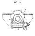
- Both side walls of the distance bracket 7 are sometimes designed to extend to a position beyond the center of the steering column 2 in order to compensate lack of rigidity in supporting the steering column 2, for example as shown in Fig. 14.
- Another countermeasure proposed for the same purpose is to dispose a spacer 11 made of a resin between the support portions 4a and 4b of the tilt bracket 4 as shown in Fig. 15.
- an object of the present invention is to provide a position adjustable steering column apparatus for a vehicle in which rigidity of supporting is improved without adding a special member for supporting the steering column.
- a position adjustable steering apparatus for a vehicle comprises:
- a position adjustable steering apparatus for a vehicle comprises:
- a position adjustable steering apparatus for a vehicle comprises:
- a position adjustable steering apparatus for a vehicle comprises:
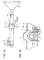
- Fig. 1A is a side view showing a tilting steering apparatus for a vehicle according to the first embodiment of the present invention.
- Fig. 1B is a cross sectional view taken along line b-b in Fig. 1A.
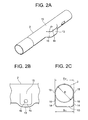
- Fig. 2A is a perspective view of the steering column
- Fig. 2B is a side view of the steering column
- Fig. 2C is a cross sectional view of the steering column.
- a steering shaft 1 having a steering wheel 100 on its top is rotatably supported in the interior of the steering column 2.
- the steering shaft 1 is supported on the steering column 2 by means of a rear side (with respect to the vehicle body) bearing 101 and a front side bearing 102.
- the steering column 2 is attached to the vehicle body at its lower end portion by means of a vehicle body side lower bracket 103, and at its mid portion by means of a vehicle body side upper bracket 4 (or a tilt bracket) which is substantially L-shaped as seen from the side.
- a column side lower bracket 104 is held inside the vehicle body side lower bracket 103 having a substantially U-shape.
- the column side lower bracket 104 may be formed integrally with the steering column 2 by a hydraulic bulge forming process, which will be described later, or alternatively it may be attached to the steering column 2 by welding.
- a cut-away portion 105 that opens to the front side of the vehicle body is formed on the vehicle body side lower bracket 103.
- a tilt center bolt 106 inserted through the column side lower bracket 104 is designed to engage the notch 105.
- the tilting steering column apparatus is equipped with a steering column 2 that supports the steering shaft 1 along its axis by means of bearings (not shown) and a clamp mechanism 3 attached to an expanded portion 13 of the steering column 2, which will be described in detail later.
- the clamp mechanism 3 comprises a tilt bracket 4, a tilt bolt 5, a nut 6, a tilt lever 8 and paired fixed and movable cams 9 and 10.
- the steering column 2 is set at the center of the tilt bracket 4 that is fixed to the vehicle body.
- the tilt bracket (the vehicle body side bracket) 4 is integrally composed of a pair of opposed flat plate portions 4a, 4b extending in the axial direction on both sides of the steering column 2 and a vehicle body mount portion 4c that is fixed to the vehicle body and extending in the transverse direction of the steering column 2.
- the pair of opposed flat portions 4a, 4b and the vehicle body mount portion 4c may be separate members.
- the vehicle body side upper bracket (the tilt bracket) 4 is designed in such a way that upon secondary collision, it moves frontward with respect to the vehicle body with the pair of opposed flat plate portions 4a, 4b being bent frontward relative to the vehicle body mount portion 4c by an impact energy imparted on the tilt bolt 5 while generating a collapse load to absorb the impact energy.
- the upper bracket 4 may be separated into a vehicle body side bracket and a column side bracket and a resin capsule or the like may be provided between those brackets so that the column side bracket can be disengaged upon secondary collision.
- the tilt bolt 5 (a shaft) is inserted through a pair of long holes 5a, 5b for allowing tilt adjustment formed on the opposed flat plate portions 4a, 4b of the tilt bracket 4, circular holes 16, 16 formed on the expanded portion 13 of the steering column 2, the tilt lever 8, the fixed cam 9 and the movable cam 10.
- the nut 6 is screwed on a threaded portion at one end of the tilt bolt 5.
- the paired fixed cam 9 and movable cam 10 are designed to engage the long hole 5a for allowing tilt adjustment on the opposed flat plate portion 4a of the tilt bracket 4 and the tilt lever 8 respectively.
- the movable cam 10 is rotated relative to the fixed cam 9 that is always non-rotatable, whereby the tilt bolt 5 (or the shaft) is pulled in its axial direction to change the distance between the pair of opposed flat plate portions 4a and 4b.
- the steering column 2 has the expanded portion 13 that was formed by expanding (or bulging) a portion of a tubular material at an axially mid portion of the column by a hydraulic bulge forming process.
- the expanded portion 13 has a pair of flat portions 14, opposed to the opposed flat plate portions 4a and 4b respectively, serving the clamp mechanism and transition portions 15 through which the tubular material changes into the flat portions 14.
- the flat portions 14 maintain a horizontal span S1, and the transition portions 15 are formed with a horizontal span S2 that is substantially equal to the span S1.
- the span S1 refers to the span of the portions at which the circular holes 16 are formed.
- this embodiment is characterized by the condition S1 ⁇ S2.
- Letting D be the diameter of the steering column, although in the illustrated example (shown in Figs. 2A to 2C) the condition S2 ⁇ D is met, this condition is not essential, but the apparatus may satisfy the condition S2 ⁇ D.
- through holes such as circular holes 16 for example, through which the tilt bolt 5 is inserted are formed by hydraulic bulge forming process.
- transition portions 15 formed with the same span as the flat portions 14 are located, with respect to the vertical direction, at a certain position between the circular holes 16 and the vehicle body mount portion 4c. Since the flat portions 14 and the transition portion 15 are formed by expanding a portion of the same member, they have the substantially the same thickness. This is also the case with the other embodiments that will be described later.
- the tilt bracket 4 and the steering column 2 can be pressed together with a strong tightening force in the transition portions 15 as well as in the flat portions 14 at which the clamp mechanism is present.
- the flat portions 14 and the transition portions 15 having substantially the same horizontal span S1, S2, when the tilt bracket 4 is in contact with the flat portions 14 and the transition portions 15, these portions are in uniform, close contact with the opposed flat plate portions 4a and 4b, so that a uniform tightening force is produced. Consequently, the tilt bracket 4 and the steering column 2 can be pressed together with a strong tightening force also in transition portions 15 as well as in the flat portions 14.
- the expanded portion 13 in this embodiment is formed by expanding a portion of the material of the steering column 2, and a large size distance bracket extending beyond the center of the steering column 2 is not used. Therefore, the weight of the steering column apparatus is not increased. Furthermore, since a special member such as a spacer made of a resin is not used, the structure of the clamp mechanism can be made simple and the steering column apparatus can be manufactured at low cost with a decreased number of parts.
- the steering column 2 when the steering column 2 is held between the opposed flat plate portions 4a and 4b of the tilt bracket 4, the steering column 2 can be brought into pressure contact with the opposed flat plate portions 4a and 4b with a strong tightening force also in the transition portions 15 as well as in the flat portions 14.
- a strong tightening force also in the transition portions 15 as well as in the flat portions 14.
- this embodiment is characterized by the condition S1 ⁇ S2.
- condition S2 ⁇ D D is the outer diameter of the steering column
- this condition is not essential, but the apparatus may satisfy the condition S2 ⁇ D.
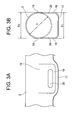
- Figs. 3A and 3B show a steering column apparatus according to the second embodiment of the present invention.
- Fig. 3A is a side view of the steering column and
- Fig. 3B is a cross sectional view of the steering column.
- the steering column of the second embodiment is telescopic type unlike the above-described first embodiment, but the structure shown in Figs. 1A and 1B (i.e. the structure and positional relationship of the clamp mechanism 3, the vehicle body side bracket 4 and the shaft 5 etc.) also applies to the steering column of the second embodiment.
- the steering column shown in Figs. 3A and 3B can be used in a telescopic apparatus or a tilting, telescopic steering apparatus.
- the steering column 2 has an expanded portion 17 formed by expanding (or bulging) a portion of a tubular material at an axially mid portion of the column by a hydraulic bulge forming process.
- the expanded portion 17 has a pair of flat portions 18 respectively opposed to the opposed flat plate portions 4a and 4b shown in Figs. 1A and 1B and transition portions 19 through which the tubular material changes into the flat portions 18.
- the flat portions 18 maintain a horizontal span S1, and the transition portions 19 are formed with a horizontal span S2 that is substantially equal to the span S1.
- the span S1 refers to the span of the portion at which long holes 20 are formed.
- this embodiment is characterized by the condition S1 ⁇ S2.
- Letting D be the diameter of the steering column, although in the illustrated example (shown in Figs. 2A to 2C) the condition S2 ⁇ D is met, this condition is not essential, but the apparatus may satisfy the condition S2 ⁇ D.
- transition portions 19 formed with the same span as the flat portions 18 are located, with respect to the vertical direction, at a certain position between the long holes 20 and the vehicle body mount portion 4c.
- pressure contact with the tilt bracket 4 can be attained also in the transition portions 19 as well as in the flat portions 18.
- the flat portions 18 and the transition portions 19 having substantially the same horizontal span S1, S2, when the opposed flat plate portions 4a, 4b are in contact with the flat portions 18 and the transition portions 19, these portions are in uniform, close contact with the opposed flat plate portions 4a and 4b, so that a uniform tightening force is produced. Consequently, pressure contact with the opposed flat plate portions 4a, 4b with a strong tightening force is realized also in transition portions 19 as well as in the flat portions 18.
- the steering column 2 when the telescopic steering column 2 is held by the bracket, the steering column 2 can be brought into pressure contact with the opposed flat plate portions 4a and 4b with a strong tightening force also in the transition portions 19 as well as in the flat portions 18.
- the steering column 2 it is possible to improve rigidity in supporting the steering column 2 without providing a special member.
- this embodiment is characterized by the condition S1 ⁇ S2.
- condition S2 ⁇ D D is the outer diameter of the steering column
- this condition is not essential, but the apparatus may satisfy the condition S2 ⁇ D.
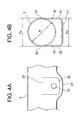
- Figs. 4A and 4B show a steering column according to the third embodiment of the present invention.
- Fig. 4A is a side view of the steering column and
- Fig. 4B is a cross sectional view of the steering column.
- the steering column of the third embodiment is of a tilting type as with the above-described first embodiment, and the structure shown in Figs. 1A and 1B (i.e. the structure and the positional relationship of the clamp mechanism 3, the vehicle body side bracket 4 and the shaft 5 etc.) also applies to the steering column of the third embodiment.
- the steering column shown in Figs. 4A and 4B can be used in a tilting steering apparatus.
- the tilting steering column 2 has an expanded portion 21 that was formed by expanding (or bulging) a portion of a tubular material at an axially mid portion of the column by a hydraulic bulge forming process.
- the expanded portion 21 has a pair of flat portions 22 respectively opposed to the opposed flat plate portions 4a and 4b shown in Fig. 1B and a pair of transition portions 23.
- the transition portions 23 maintain a horizontal span S4 substantially equal to the diameter D of the steering column 2, and the flat portions 22 are formed with a horizontal span S3 that is slightly smaller than the span S4.
- the span S3 refers to the span of the portions at which circular holes 16 are formed.
- S3 and S4 are connected by a slope, namely they are on the same plane.
- transition portions 23 formed with the span S4 different from that of the flat portions 22 are located, with respect to the vertical direction, at a certain position between the circular holes 16 and the vehicle body mount portion 4c.
- the steering column 2 when the steering column 2 is held between the opposed flat plate portions 4a and 4b, the steering column 2 can be brought into pressure contact with the opposed flat plate portions 4a and 4b with a strong tightening force in the transition portions 23 having the span S4 larger than the span S3 of the flat portions 22.
- a strong tightening force in the transition portions 23 having the span S4 larger than the span S3 of the flat portions 22 it is possible to enhance rigidity in supporting the steering column 2 without providing a special member.
- Figs. 5A and 5B show a steering column according to the fourth embodiment of the present invention.
- Fig. 5A is a side view of the steering column and
- Fig. 5B is a cross sectional view of the steering column.
- the steering column of the fourth embodiment is of a tilting type as with the above-described first embodiment, and the structure shown in Figs. 1A and 1B (i.e. the structure and the positional relationship of the clamp mechanism 3, the vehicle body side bracket 4 and the shaft 5 etc.) also applies to the steering column of the fourth embodiment.
- the steering column shown in Figs. 5A and 5B can be used in a tilting steering apparatus.
- the tilting steering column 2 has paired first and second expanded portions 24a and 24b formed by expanding (or bulging) a portion of tubular material upwardly and downwardly at an axially mid portion of the column by a hydraulic bulge forming process.
- the first expanded portion 24a has a pair of first flat portions 25, 25 opposed to the opposed flat plate portions 4a, 4b shown in Figs. 1A and 1B.
- the second expanded portion 24b has a pair of second flat portions 26, 26 located between circular holes 16 and the vehicle body mount portion 4c.
- the first flat portions 25 are formed with a horizontal span S3 and the second flat portions 26 are formed with a horizontal span S4 equal to or slightly larger than the span S3.
- the span S3 refers to the span of the portions at which the circular holes 16 are formed.
- this embodiment is characterized by the condition S4 ⁇ S3.
- either S3 or S4 is equal to D.
- this condition is not essential, but the apparatus may satisfy the condition (S3, S4)>D or the condition (S3, S4) ⁇ D.
- first flat portion 25 and the second flat portion 26 may be coplanar.
- the second flat portions 26 having the span S4 equal to or larger than the span S3 of the first flat portions 25. Accordingly, even if offset is present between the center of the clamp mechanism and the second flat portions 26, the tightening force of the clamp mechanism can be exerted on both the first flat portions 25 and the second flat portions 26 uniformly.
- first flat portions 25 and the second flat portions 26 (located between the circular holes 16 and the vehicle body mount portion 4c) have horizontal spans S3 and S4 significantly larger than the outer diameter D of the steering column 2, as shown in Figs. 6A and 6B.
- the first flat portions 25 are formed with a horizontal span S3 and the second flat portions 26 are formed with a horizontal span S4 equal to or slightly larger than the span S4.
- the span S3 refers to the span of the portions at which the circular holes 16 are formed.
- this modification is characterized by the condition S4 ⁇ S3.
- condition S4>S5 and the condition S3>S5 are met in this modification.
- S5 is equal to D.
- this condition is not essential, but the condition S5>D or S5 ⁇ D may be met.
- the first flat portion 25 and the second flat portion 26 may be coplanar.
- Fig. 7 is a side view showing a tilting telescopic steering apparatus for a vehicle according to the fifth embodiment of the present invention.
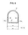
- Fig. 8 is a cross sectional view taken along line A-A in Fig. 7, showing only the expanded portion of the steering column.
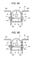
- Fig. 9A is a cross sectional view taken along line A-A in Fig. 7, showing a state in which clamping of the column is released.
- Fig. 9B is a similar cross sectional showing a state in which the column is clamped.
- a steering shaft 32 is rotatably supported on a steering column 31, and a steering wheel 33 is attached on the rear end (with respect to the vehicle body) of the steering shaft 32.
- the central portion of the steering column 31 is supported on a vehicle body mount upper bracket 35 in a swingable way.
- the vehicle body mount upper bracket 35 is fixed to the vehicle body.
- the vehicle body mount upper bracket 35 has a pair of horizontal portions 35a, 35a (vehicle body mount portions) extending transversely to the steering column 31 and a pair of opposed flat plate portions 35b, 35b that are integral with the pair of horizontal portions 35a, 35a and extended downward from them to extend in the axial direction on both sides of the steering column 31.
- a pair of long holes 36, 36 for allowing tilt adjustment are formed on the pair of opposed flat plate portions 35b, 35b.
- the pair of horizontal portions 35a, 35a and the pair of opposed flat plate portions 35b, 35b may be formed as separate members.
- An expanded portion 37 is formed at the axially central portion of the steering column 31 by a hydroforming process.
- both side portions 37a, 37a that are in contact with the opposed flat plate portions 35b, 35b of the vehicle body mount upper bracket 35 respectively so as to be supported by the vehicle body mount upper bracket 35 are integrally formed.
- On both the side portions 37a, 37a a pair of long holes 38, 38 for allowing tilt adjustment are formed.
- a tightening bolt 39 provided with a clamp mechanism 48 is inserted through the pair of tilt adjustment long holes 36, 36 and the pair of column position adjustment long holes 38, 38.
- An operation lever 40 is rotatably mounted on the tightening bolt 39.
- the clamp mechanism 48 may be a well known mechanism including a cam mechanism.
- the lower, front (with respect to the vehicle body) portion of the steering column 31 is supported by a vehicle body mount lower bracket 34 in a swingable way.
- the vehicle body mount lower bracket 34 is fixed to the vehicle body.
- the vehicle body mount lower bracket 34 has a pair of horizontal portions 34a, 34a extending transversely to the steering column 31 and a pair of opposed flat plate portions 34b, 34b that are integral with the pair of horizontal portions 34a, 34a and extended downward from them to extend in the axial direction on both sides of the steering column 31.
- a pair of bracket supporting holes 34c, 34c are formed on the pair of opposed flat plate portions 34b, 34b.
- a support bracket portion 44 is attached by, for example, welding.
- the support bracket portion 44 has both side portions 44a, 44a that are in contact with the opposed flat plate portions 34b, 34b of the vehicle body mount lower bracket 34 respectively so as to be supported.
- a pair of long holes 46, 46 for allowing column position adjustment are formed on both the side portions 44a, 44a.
- the support bracket portion 44 is supported by the vehicle body mount bracket 34 in a slidable and rotatable manner by means of the long holes 46, 46 and the bracket supporting holes 34c, 34c and hinge pins 45, 45.
- the tilting telescopic steering apparatus has the above-described structure.
- the support bracket portion 44 is formed integrally with the steering column 31 by a hydroforming process that will be described later.
- the supporting bracket portion 44 and the steering column 31 may be formed as separate members.
- the operation lever 40 is rotated in the tightening direction.
- the distance between the head of the tightening bolt 39 and an adjustment nut 41 is decreased, so that the pair of opposed flat plate portions 35b, 35b of the vehicle body mount upper bracket 35 are securely pressed against both the side portions 37a, 37a of the expanded portion 37 of the steering column 31.
- the tilt and telescopic adjusted position of the steering column 31 is fixed.
- the operation lever is rotated in the releasing direction.
- the distance between the head of the tightening bolt 39 and the adjustment nut 41 is increased, so that secure pressure contact of the pair of opposed flat plate portions 35b, 35b of the vehicle body mount upper bracket 35 and both the side portions 37a, 37a of the expanded portion 37 of the steering column 31 is released.
- adjustment of the tilt and telescopic position of the steering column 31 is allowed.
- the steering column 31 can be adjusted to a desired tilt and telescopic position.
- a single blank in the form of a steel tube material is formed into a steering column 31 having an integral expanded portion 37 by a hydroforming process.
- the pair of long holes 38, 38 for allowing column position adjustment through which the tightening bolt 39 provided with the clamp mechanism 48 is inserted are formed.
- the clamp mechanism 48 may include the cam mechanism used in the first embodiment.
- both the side portions 37a, 37a of the expanded portion 37 are slanted in such a way that the distance (Dd) therebetween at the lower end is slightly smaller than the distance (Du) therebetween at the upper end.
- the distance Du is the span of the portions at which the long holes 38 for allowing column position adjustment are formed.
- the contact area of those members can be increased and the force for securing the steering column 31 on the vehicle body can be increased. This leads to improvement in rigidity against vibration and an increase in the securing force upon collision.
- the hydroforming is a method of placing a thin-walled steel pipe in a metallic mold and filling the interior of the steel pipe with pressurized water or pressurized oil to expand the steel pipe to shape it into a desired form or simply filling the interior of the pipe with rubber or the like to expand it.
- This method is advantageous over the process of forming a member having a closed cross sectional structure by welding after press molding, since the product will not be much deformed by heat thanks to the lack of a welded portion and therefore processing or manufacturing cost reduction and weight reduction can be expected.
- the expanded portion 7 has a closed cross sectional structure integral with the steering column 31, the steering column 31 itself can be made rigid and the force for securing the steering column 31 to the vehicle body can be made strong.
- the manufacturing cost including the material cost, processing cost and assembling cost
- the weight can be reduced.
- the production method is not limited to the hydroforming process, but the steering column may be formed by a rubber bulge forming process, an explosion bulge forming process or a pressing process.
- condition Dd ⁇ Du is met.
- condition Du ⁇ D is met.
- this condition is not essential, but the condition Du ⁇ D may be met.
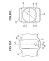
- Fig. 10A is an enlarged side view showing a portion of interest of a steering column of a tilting steering apparatus for a vehicle according to the sixth embodiment of the present invention.
- Fig. 10B is a cross sectional view taken along line b-b in Fig. 10A.
- the steering column in the sixth embodiment is of a tilting type as with the above-described first embodiment, and the structure shown in Figs. 1A and 1B (i.e. the structure and positional relationship of the clamp mechanism 3, the vehicle body side bracket 4, and the shaft 5 etc.) also applies to the steering column according to the sixth embodiment.
- the steering column shown in Figs. 10A and 10B can be used in a tilting steering apparatus.
- the tilting steering column 51 has paired first and second expanded portions 52a and 52b formed by expanding (or bulging) a portion of tubular material upwardly and downwardly at a certain position in the axial direction of the column by a hydraulic bulge forming process.
- the first expanded portion 52a has a pair of first flat portions 53, 53 opposed to the opposed flat plate portions 4a, 4b shown in Figs. 1A and 1B.
- the second expanded portion 52b has a pair of second flat portions 54, 54 located between circular holes 55 and the vehicle body mount portion 4c.
- the first flat portions 53 have a horizontal span X that is smaller than the horizontal span W of transition portions between the first and second flat portions 53 and 54. In other words, the condition W ⁇ X is met.
- the span X refers to the span of the portions at which circular holes 55 are formed.
- the second flat portions 54 have a horizontal span Y that is smaller than the span W. In other words, the condition W ⁇ Y is met.
- the span Y refers to the span of the upper portions of the second flat portions 54.
- Fig. 11 is a transverse cross sectional view of a tilting steering apparatus for a vehicle according to the seventh embodiment of the present invention.
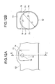
- Fig. 12A is an enlarged side view showing a portion of interest of the steering column of the tilting steering apparatus for a vehicle according to the seventh embodiment of the present invention.
- Fig. 12B is a cross sectional view taken along line b-b in Fig. 12A.
- the tilting steering column apparatus has a steering column 62 for supporting a steering shaft 61 along its axis via a bearing (not shown) and a clamp mechanism 63 attached to an expanded portion 73 of the steering column 62.
- the clamp mechanism 63 comprises a tilt bracket 64, a tilt bolt (a shaft) 65, a nut 66, a tilt lever 68 and paired fixed and movable cams 69 and 70.
- the tilt bracket 64 (i.e. the vehicle body side bracket) is integrally composed of a pair of opposed flat plate portions 64a, 64b extending axially on both sides of the steering column and a vehicle body mount portion 64c extending transversely to the steering column 61.
- the pair of opposed flat plate portions 64a, 64b and the vehicle body mount portion 64c may be formed as separate members.
- long holes 79a and 79b for allowing tilt adjustment are formed respectively.
- the vehicle body mount portion 64c is disposed below the center axis of the steering column 62, and the pair of opposed flat plate portions 64a, 64b extend substantially upwardly from the vehicle body mount portion 64c.
- the tilt bolt (shaft) 65 is inserted through the opposed flat plate portions 64a, 64b of the tilt bracket 64, an expanded portion of the steering column 62, the tilt lever 68, the fixed cam 69 and the movable cam 70.
- the nut 66 is screwed on a threaded portion at one end of the tilt bolt 65.
- the paired fixed and movable cams 69 and 70 engage the flat plate portion 64a and the tilt lever 68 respectively.
- the tilt lever 68 As the tilt lever 68 is rotated, the movable cam 70 rotates relative to the fixed cam 69, which is always non-rotatable, whereby the tilt bolt (shaft) 65 is pulled in its axial direction, so that the distance between the pair of opposed flat plate portions 64a and 64b is changed.
- the steering column 62 has an expanded portion 73 formed by expanding (or bulging) a portion of a tubular material at an axially mid portion of the column by a hydraulic bulge forming process.
- the expanded portion 73 has a pair of flat portions 74 opposed to the opposed flat plate portions 64a and 64b respectively for serving the clamp mechanism 63 and transition portions 75 through which the tubular material changes into the flat portions 74.
- the flat portions 74 have a span Z1 that is smaller than the span Z2 of the transition portions 75. In other words the condition Z2>Z1 is met.
- the span Z1 refers to the span of the portions at which circular holes 76 are formed.
- Z2 and D may be of any relationship.
- through holes, or the circular holes 76 for example, through which the tilt bolt (or the shaft) is inserted are formed by hydraulic bulge forming process.
- the tilt bracket 64 and the steering column 62 can be pressed together with a strong tightening force in the transition portions 75 as well as in the flat portions 74 at which the clamp mechanism is present.
- the steering column 62 when the steering column 62 is held between the opposed flat plate portions 64a and 64b of the tilt bracket 64, the steering column 62 can be brought into pressure contact with the opposed flat plate portions 64a and 64b with a strong tightening force also in the transition portions 75 as well as in the flat portions 74.
- a strong tightening force also in the transition portions 75 as well as in the flat portions 74.
- the position adjustable steering column apparatus for a vehicle according to the present invention may be any of the tilting, telescopic and tilting-telescopic types.
Landscapes
- Engineering & Computer Science (AREA)
- Chemical & Material Sciences (AREA)
- Combustion & Propulsion (AREA)
- Transportation (AREA)
- Mechanical Engineering (AREA)
- Steering Controls (AREA)
Applications Claiming Priority (5)
| Application Number | Priority Date | Filing Date | Title |
|---|---|---|---|
| JP2002258402 | 2002-09-04 | ||
| JP2002258402 | 2002-09-04 | ||
| JP2002300631 | 2002-10-15 | ||
| JP2002300631 | 2002-10-15 | ||
| PCT/JP2003/009863 WO2004022410A1 (ja) | 2002-09-04 | 2003-08-04 | 車両用位置調整式ステアリングコラム装置 |
Publications (2)
| Publication Number | Publication Date |
|---|---|
| EP1547902A1 true EP1547902A1 (de) | 2005-06-29 |
| EP1547902A4 EP1547902A4 (de) | 2006-11-29 |
Family
ID=31980573
Family Applications (1)
| Application Number | Title | Priority Date | Filing Date |
|---|---|---|---|
| EP03794075A Withdrawn EP1547902A4 (de) | 2002-09-04 | 2003-08-04 | Lenksäulenvorrichtung der fahrzeugpositionseinstellungsart |
Country Status (5)
| Country | Link |
|---|---|
| US (1) | US20060156854A1 (de) |
| EP (1) | EP1547902A4 (de) |
| JP (1) | JPWO2004022410A1 (de) |
| AU (1) | AU2003252368A1 (de) |
| WO (1) | WO2004022410A1 (de) |
Cited By (4)
| Publication number | Priority date | Publication date | Assignee | Title |
|---|---|---|---|---|
| DE102011054598B3 (de) * | 2011-10-19 | 2013-01-17 | Thyssenkrupp Presta Ag | Lenkspindellagereinheit zur drehbaren Lagerung einer Lenkspindel |
| DE102011054606B3 (de) * | 2011-10-19 | 2013-02-28 | Thyssenkrupp Presta Aktiengesellschaft | Lenkspindellagereinheit zur drehbaren Lagerung einer Lenkspindel |
| WO2013056771A1 (de) | 2011-10-19 | 2013-04-25 | Thyssenkrupp Presta Aktiengesellschaft | Lenkspindellagereinheit |
| US8991862B2 (en) | 2011-10-19 | 2015-03-31 | Thyssenkrupp Presta Aktiengesellschaft | Steering column for a motor vehicle |
Families Citing this family (6)
| Publication number | Priority date | Publication date | Assignee | Title |
|---|---|---|---|---|
| EP1498340B1 (de) * | 2002-04-17 | 2009-04-01 | Nsk Ltd. | Verfahren zur montage von lenksäulen |
| JP4683456B2 (ja) * | 2003-07-16 | 2011-05-18 | 日本精工株式会社 | ステアリング装置 |
| US7942446B2 (en) * | 2004-04-30 | 2011-05-17 | Nexteer (Beijing) Technology Co., Ltd. | Horizontal hybrid collapsing steering column |
| JP4951258B2 (ja) * | 2006-03-29 | 2012-06-13 | 富士機工株式会社 | ステアリングコラム装置 |
| CN102026860B (zh) * | 2008-05-16 | 2014-03-12 | 采埃孚转向机系统纳凯姆联合股份公司 | 用于调节汽车中的转向柱位置的装置 |
| JP6003110B2 (ja) * | 2012-03-08 | 2016-10-05 | 日本精工株式会社 | ステアリング装置の製造方法 |
Family Cites Families (14)
| Publication number | Priority date | Publication date | Assignee | Title |
|---|---|---|---|---|
| JPS59117575U (ja) * | 1983-01-31 | 1984-08-08 | 日産ディーゼル工業株式会社 | 自動車のステアリング支持装置 |
| JPH08225079A (ja) * | 1995-02-20 | 1996-09-03 | Nippon Seiko Kk | 衝撃吸収式ステアリングコラム |
| JP3440605B2 (ja) * | 1995-02-27 | 2003-08-25 | 日本精工株式会社 | チルト式ステアリング装置 |
| JPH08276852A (ja) * | 1995-04-03 | 1996-10-22 | Nippon Seiko Kk | チルト式ステアリング装置 |
| DE19531278C1 (de) * | 1995-08-25 | 1997-01-30 | Daimler Benz Ag | Gelenk zur Schwenklagerung eines Mantelrohrs einer neigungseinstellbaren Lenksäule an einer Mantelrohraufhängung eines Fahrzeugs |
| GB2304866A (en) * | 1995-09-11 | 1997-03-26 | Nastech Europ Ltd | Adjustable vehicle steering column |
| JP3567623B2 (ja) * | 1996-06-21 | 2004-09-22 | 日本精工株式会社 | チルト式ステアリング装置 |
| DE19629246A1 (de) * | 1996-07-19 | 1998-01-22 | Opel Adam Ag | Vorrichtung zur Verriegelung einer verstellbaren Lenksäule, insbesondere für Kraftfahrzeuge |
| JP2000118415A (ja) * | 1998-10-09 | 2000-04-25 | Fuji Kiko Co Ltd | ステアリングコラム |
| DE60133331T3 (de) * | 2000-02-15 | 2012-12-06 | Nsk Ltd. | Lenkung für ein Automobil |
| US6474189B1 (en) * | 2000-10-26 | 2002-11-05 | Trw Inc. | Apparatus for mounting a foot pedal and a steering column to a vehicle |
| JP2003118595A (ja) * | 2001-08-06 | 2003-04-23 | Nsk Ltd | 車両用ステアリング装置及びその製造方法 |
| JP4179049B2 (ja) * | 2002-07-16 | 2008-11-12 | 日本精工株式会社 | 位置調整式ステアリングコラム装置 |
| WO2004011317A1 (ja) * | 2002-07-25 | 2004-02-05 | Nsk Ltd. | ステアリングコラム装置 |
-
2003
- 2003-08-04 JP JP2004534100A patent/JPWO2004022410A1/ja active Pending
- 2003-08-04 EP EP03794075A patent/EP1547902A4/de not_active Withdrawn
- 2003-08-04 AU AU2003252368A patent/AU2003252368A1/en not_active Abandoned
- 2003-08-04 US US10/526,459 patent/US20060156854A1/en not_active Abandoned
- 2003-08-04 WO PCT/JP2003/009863 patent/WO2004022410A1/ja not_active Ceased
Cited By (10)
| Publication number | Priority date | Publication date | Assignee | Title |
|---|---|---|---|---|
| DE102011054598B3 (de) * | 2011-10-19 | 2013-01-17 | Thyssenkrupp Presta Ag | Lenkspindellagereinheit zur drehbaren Lagerung einer Lenkspindel |
| DE102011054606B3 (de) * | 2011-10-19 | 2013-02-28 | Thyssenkrupp Presta Aktiengesellschaft | Lenkspindellagereinheit zur drehbaren Lagerung einer Lenkspindel |
| WO2013056771A1 (de) | 2011-10-19 | 2013-04-25 | Thyssenkrupp Presta Aktiengesellschaft | Lenkspindellagereinheit |
| DE102011054597A1 (de) | 2011-10-19 | 2013-04-25 | Thyssenkrupp Presta Aktiengesellschaft | Lenkspindellagereinheit |
| WO2013056765A1 (de) | 2011-10-19 | 2013-04-25 | Thyssenkrupp Presta Aktiengesellschaft | Lenkspindellagereinheit zur drehbaren lagerung einer lenkspindel |
| WO2013056764A1 (de) | 2011-10-19 | 2013-04-25 | Thyssenkrupp Presta Aktiengesellschaft | Lenkspindellagereinheit zur drehbaren lagerung einer lenkspindel |
| US8991862B2 (en) | 2011-10-19 | 2015-03-31 | Thyssenkrupp Presta Aktiengesellschaft | Steering column for a motor vehicle |
| US9010807B2 (en) | 2011-10-19 | 2015-04-21 | Thyssenkrupp Presta Aktiengesellschaft | Steering shaft bearing unit for rotatably mounting a steering shaft |
| US9022427B2 (en) | 2011-10-19 | 2015-05-05 | Thyssenkrupp Presta Aktiengeesllscahft | Steering shaft bearing unit |
| US9233706B2 (en) | 2011-10-19 | 2016-01-12 | Thyssenkrupp Presta Aktiengesellschaft | Steering shaft bearing unit for rotatably mounting a steering shaft |
Also Published As
| Publication number | Publication date |
|---|---|
| WO2004022410A1 (ja) | 2004-03-18 |
| JPWO2004022410A1 (ja) | 2005-12-22 |
| AU2003252368A1 (en) | 2004-03-29 |
| EP1547902A4 (de) | 2006-11-29 |
| US20060156854A1 (en) | 2006-07-20 |
Similar Documents
| Publication | Publication Date | Title |
|---|---|---|
| EP2236392B1 (de) | Lenkvorrichtung für Fahrzeug | |
| US7699344B2 (en) | Steering device | |
| US20070068311A1 (en) | Steering apparatus | |
| JP5309605B2 (ja) | ステアリング装置 | |
| US7325833B2 (en) | Steering device for motor vehicle | |
| EP1547902A1 (de) | Lenksäulenvorrichtung der fahrzeugpositionseinstellungsart | |
| EP2716520B1 (de) | Lenksäulenvorrichtung | |
| JP2012096772A (ja) | ステアリング装置 | |
| JP2007223383A (ja) | ステアリング装置 | |
| CN102958779A (zh) | 汽车用转向装置 | |
| JP5737297B2 (ja) | ステアリング装置 | |
| EP1550598B1 (de) | Lenkstulenvorrichtung | |
| JPWO2004005109A1 (ja) | 車両用衝撃吸収式ステアリングコラム装置 | |
| JPWO2004011317A1 (ja) | ステアリングコラム装置 | |
| JP5082871B2 (ja) | 車両用ステアリング装置 | |
| US20040084886A1 (en) | Extendable and contractable steering column apparatus | |
| JP4335578B2 (ja) | 車両用位置調整式ステアリングコラム装置 | |
| JP5522293B2 (ja) | ステアリング装置 | |
| JP2006117120A (ja) | ステアリング装置 | |
| JP4120375B2 (ja) | ステアリングコラム装置及びその製造方法 | |
| JP3969186B2 (ja) | 車両用ステアリング装置及びその製造方法 | |
| JP5459427B2 (ja) | ステアリング装置 | |
| JP6003110B2 (ja) | ステアリング装置の製造方法 | |
| JP2004359101A (ja) | ステアリングコラム装置 | |
| JP2008265573A (ja) | 車両用衝撃吸収式ステアリングコラム装置 |
Legal Events
| Date | Code | Title | Description |
|---|---|---|---|
| PUAI | Public reference made under article 153(3) epc to a published international application that has entered the european phase |
Free format text: ORIGINAL CODE: 0009012 |
|
| 17P | Request for examination filed |
Effective date: 20050331 |
|
| AK | Designated contracting states |
Kind code of ref document: A1 Designated state(s): AT BE BG CH CY CZ DE DK EE ES FI FR GB GR HU IE IT LI LU MC NL PT RO SE SI SK TR |
|
| AX | Request for extension of the european patent |
Extension state: AL LT LV MK |
|
| RBV | Designated contracting states (corrected) |
Designated state(s): DE GB |
|
| DAX | Request for extension of the european patent (deleted) | ||
| A4 | Supplementary search report drawn up and despatched |
Effective date: 20061026 |
|
| RIC1 | Information provided on ipc code assigned before grant |
Ipc: B62D 1/184 20060101AFI20061020BHEP |
|
| 17Q | First examination report despatched |
Effective date: 20070723 |
|
| STAA | Information on the status of an ep patent application or granted ep patent |
Free format text: STATUS: THE APPLICATION IS DEEMED TO BE WITHDRAWN |
|
| 18D | Application deemed to be withdrawn |
Effective date: 20090116 |