EP1546013B1 - Verfahren und apparat zum falzen von blättern - Google Patents
Verfahren und apparat zum falzen von blättern Download PDFInfo
- Publication number
- EP1546013B1 EP1546013B1 EP03770605A EP03770605A EP1546013B1 EP 1546013 B1 EP1546013 B1 EP 1546013B1 EP 03770605 A EP03770605 A EP 03770605A EP 03770605 A EP03770605 A EP 03770605A EP 1546013 B1 EP1546013 B1 EP 1546013B1
- Authority
- EP
- European Patent Office
- Prior art keywords
- fold
- fold blade
- sheet
- spring members
- receptacle
- Prior art date
- Legal status (The legal status is an assumption and is not a legal conclusion. Google has not performed a legal analysis and makes no representation as to the accuracy of the status listed.)
- Expired - Lifetime
Links
- 238000000034 method Methods 0.000 title claims description 8
- 239000000463 material Substances 0.000 claims description 23
- 238000000576 coating method Methods 0.000 claims description 3
- 239000002184 metal Substances 0.000 claims description 3
- 238000009966 trimming Methods 0.000 claims description 3
- 239000011248 coating agent Substances 0.000 claims description 2
- 230000008878 coupling Effects 0.000 description 6
- 238000010168 coupling process Methods 0.000 description 6
- 238000005859 coupling reaction Methods 0.000 description 6
- 230000004913 activation Effects 0.000 description 2
- 238000004891 communication Methods 0.000 description 2
- 238000003825 pressing Methods 0.000 description 2
- 230000008569 process Effects 0.000 description 2
- 238000004080 punching Methods 0.000 description 2
- 230000009471 action Effects 0.000 description 1
- 230000003213 activating effect Effects 0.000 description 1
- 230000001154 acute effect Effects 0.000 description 1
- 230000000712 assembly Effects 0.000 description 1
- 238000000429 assembly Methods 0.000 description 1
- 238000005452 bending Methods 0.000 description 1
- 230000015572 biosynthetic process Effects 0.000 description 1
- 238000002788 crimping Methods 0.000 description 1
- 230000001186 cumulative effect Effects 0.000 description 1
- 229920001971 elastomer Polymers 0.000 description 1
- 239000000806 elastomer Substances 0.000 description 1
- 229920001296 polysiloxane Polymers 0.000 description 1
- 229920001343 polytetrafluoroethylene Polymers 0.000 description 1
- 239000004810 polytetrafluoroethylene Substances 0.000 description 1
- 230000002265 prevention Effects 0.000 description 1
- 230000000087 stabilizing effect Effects 0.000 description 1
Images






Classifications
-
- B—PERFORMING OPERATIONS; TRANSPORTING
- B65—CONVEYING; PACKING; STORING; HANDLING THIN OR FILAMENTARY MATERIAL
- B65H—HANDLING THIN OR FILAMENTARY MATERIAL, e.g. SHEETS, WEBS, CABLES
- B65H45/00—Folding thin material
- B65H45/12—Folding articles or webs with application of pressure to define or form crease lines
- B65H45/18—Oscillating or reciprocating blade folders
Definitions
- the present invention generally relates to folding sheet material and, more particularly, to a sheet folding apparatus using flexible spring members which are arranged to move with respect to a fold blade to fold a sheet of material.
- the Trovinger PCT includes an operation where individual booklet sheets are folded using two drive motor assemblies.
- a first vertical drive motor assembly operates to immobilize a sheet by pressing it against a fold blade with a folder assembly.
- This first vertical drive motor assembly moves a set of fold rollers into contact with both the sheet and a longitudinal fold blade.
- the axes of rotation for the fold rollers are perpendicular to the fold blade used to fold each sheet.
- a second horizontal drive motor then operates to deform the sheet against the fold blade by reciprocating the set of fold rollers, which have been placed into contact with the sheet, back and forth along the fold blade to crease the sheet.
- the number and spacing of these fold rollers are such that during horizontal movement of the fold rollers, at least one fold roller passes over every point along the portion of a sheet where a fold is to be formed.
- the system described in the Trovinger PCT uses two separate motors to establish linear motion of fold rollers in two axes to create a fold.
- the time to create a fold includes the cumulative time of moving a folder assembly vertically and moving the fold rollers horizontally to crease the sheet.
- the Lane patent includes a blade for forcing once-folded paper (e.g., a folded stack of newsprint) between a pair of rollers, thus creating a quarter-fold in the paper.
- Air flow jets and plates are used in the Lane patent to prevent bending of the paper edges and corners.
- the Lane patent is designed for folding entire stacks of sheets and generally does not make precise, sharp folds, or ensure proper paper alignment during a fold process.
- the present invention is directed to an apparatus that folds sheet material using a fold blade and flexible spring members.
- a sheet folding apparatus including a fold blade, a clamp movable to engage the fold blade, and a fold blade receptacle having two flexible spring members biased toward one another by pre-loading material of the spring members, wherein the fold blade and the fold blade receptacle are movable toward one another to fold a sheet of material.
- an apparatus for folding sheet material including a fold blade, clamping means for clamping a sheet against the fold blade, folding means for folding the sheet over the fold blade, the folding means including two flexible spring members for receiving the fold blade between the fingers, and drive means for moving at least one of the fold blade and the folding means into a position where the fold blade is between the two flexible spring members and the sheet is folded over the fold blade and between the fingers.
- a method for folding sheet material comprises the steps of: feeding a sheet into an area between a fold blade and a fold blade receptacle; clamping the sheet against the fold blade with a clamp; and folding the sheet by moving the fold blade and the fold blade receptacle relative to one another to form a fold in the sheet by a biasing force pre-loaded in a material the fold blade receptacle.
- Fold blade 104 is shown to be held by a blade holder 106, but can alternatively be held by any other stabilizing structure or can be manufactured with blade holder 106 as a unitary component.
- Fold blade 104 can be fixed or can alternatively be movable (for example, along the y-axis of FIG. 1A, or any desired axis) by using a device such as a blade motor.
- fold blade 104 can be positioned in a plane which passes between the two flexible spring members 118.
- Fold blade 104 can be made of metal or any other formable material, and can be shaped as a flat strip, as shown, or can include a rounded shape, these examples being non-limiting, of course.
- the cross-section of fold blade 104 can alternatively be triangular, or the blade faces can be concave or convex, instead of flat as shown.
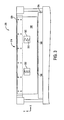
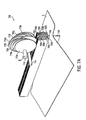
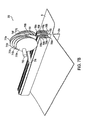
- Flexible spring members 118 as shown in FIGS. 1A-1C and FIG. 2, include six independent spring members mounted on support 120 in three pairs with two clamps 108 positioned between the pairs of flexible spring members to pinch and hold sheet S against fold blade 104 during folding.
- the flexible spring members each include a first end 122 secured to support 120 and a free end or a cantilevered portion 124.
- cantilevered portions 124 of flexible spring members 118 are substantially L-shaped and are spring biased into contact with one another prior to folding.
- the entire flexible spring members 120 are substantially Z- or S-shaped. During folding of sheet S, flexible spring members 118 flex outward with the central portions of the flexible spring members pressing the sheet against the fold blade.
- a pre-loaded spring force of the flexible spring members 118 can be selected to achieve an optimal sharp fold with a minimum damage to the sheet material.
- the pre-loaded force of the flexible spring members 118 may be varied by changing many factors, including material, shape, and thickness of flexible spring members 118 and a thickness T of support 120.
- flexible spring members 118 are arranged with spaces between adjacent pairs of spring fingers for receiving clamps 108 and springs 110. Clamps 108 and springs 110 can be located at a position at which the booklet will subsequently be stapled. Thus, in a booklet which is made with two staples, a fold blade receptacle 114 having two clamps 108 and three pairs of flexible spring members 118, would be preferred. However, it should be understood that any number of flexible spring members 118 and clamps 108 may be employed. A width of clamps 108 and springs 110 in the X direction in FIG. 2, can be minimized to reduce the area of the sheet where less sharp fold is made.
- cantilevered ends 124 of flexible spring members 118 illustrated are substantially L-shaped, it should be understood that other shapes may be employed, such as C- or U-shaped spring members.
- Fold blade 104 and fold blade receptacle 114 are moved with respect to one another to achieve folding of sheet S. This motion may be provided by moving one or both of fold blade 104 and fold blade receptacle 114. As shown in FIG. 2, they may be movable by providing couplings 126 which are moveable on rails 128 by a drive means which will be discussed in further detail with respect to FIG. 6.
- FIG. 3 illustrates an alternative embodiment of a folding apparatus 300 having a fold blade 304 and a fold blade receptacle 314.
- fold blade receptacle 314 includes two continuous flexible spring members 318 having openings 322 for receiving springs 310 of clamps 308.
- This alternative embodiment of FIG. 3 may provide simplified assembly of folding apparatus 300 and reduced likelihood of damage to sheets due to contact with edges of flexible spring members 318. Openings 322 are provided at the central portions of flexible spring members 318 which are closest together (between the fixed ends and the cantilevered ends) and allows springs 310 as well as clamps 308 to move freely within fold blade receptacle 314.
- FIG. 4 illustrates an alternative embodiment of a folding apparatus 400 having a fold blade 404 and a fold blade receptacle 414.
- fold blade receptacle 414 includes flexible spring members 418, each having a roller 422 mounted thereon.
- Fold blade receptacle 414 includes clamps 408 supported by springs 410 and flexible spring members 418 supported on support 420.
- fold blade rollers 422 are each mounted in an opening 430 in an associated flexible spring member 418 by a shaft 432.
- Shaft 432 can be fixed to flexible spring members 418 in any known manner, such as by crimping the shaft to the metal of the of the flexible spring members.
- Rollers 422 are provided to reduce friction between flexible spring members 418 and sheet S and to reduce the possibility of damage to the sheet. Rollers 422 may be coated with an elastomer to further conform to fold blade 404 and form a sharp fold.
- each of flexible spring members 118, 318, 418 have a fixed end fixed to the support and a free end.
- the free ends of flexible spring members 118, 318, 418 are cantilevered and biased toward one another.
- the center portions of the flexible spring members 118, 318, 418 between the fixed and free ends are biased to contact fold blade 104, 304, 404 (and the sheet) when the fold blade and receptacle are moved toward each other.
- flexible spring members 118, 318, 418 can provide an inwardly directed force of about 1 to about 10 lbs for folding 81 ⁇ 2 inch wide sheets.
- the force for folding may be somewhat lower for very thin papers or somewhat higher for thicker papers.
- a friction reducing coating can be provided on flexible spring members 118, 318, 418 to prevent damage to the sheets. Examples of friction reducing coatings are PTFE and silicone.
- selection of materials and deburring procedures may be used to reduce friction and possible damage to sheets.
- Fold rollers 422 of FIGS. 4 and 5 are also used to prevent damage to sheet S caused by the inwardly directed force of flexible spring members 418.
- FIG. 6 illustrates an alternative embodiment of a folding apparatus 600 including a fold blade 604, a fold blade receptacle 614, and a drive means 630.
- Fold blade receptacle 614 includes a plurality of flexible spring members 618 mounted on a support 620 and clamps 608 positioned in spaces between the flexible spring members.
- a drive means such as drive means 630 in FIG. 6, can be provided for moving at least one of fold blade 604 and fold blade receptacle 614 into operable communication with one another.
- operable communication means placement of fold blade 604 and/or fold blade receptacle 614 relative to one another to achieve a desired fold in a sheet.
- drive means 630 includes a coupling, such as coupling 632, and an actuator, such as lead screw 634, attached to the coupling, wherein rotation of the lead screw in a first direction is operable to move fold blade receptacle 614 against fold blade 604 to create a fold in a sheet.
- an actuator such as lead screw 634
- drive means 630 includes coupling 632, lead screw 634, and motor 636.
- Motor 636 can be of any conventional type (such as electric, pneumatic, or hydraulic), or can be of any other type.
- the exemplary lead screw 634 can be rotated by motor 636 via a drive belt or alternatively via any other power transmitting element, such as a chain, or can be replaced by another type of actuator, such as a piston.
- the exemplary coupling 632 includes linking members 638, which are rotatably attached to traveling members 640 and support 620 at pivot points P 1 and P 2 , respectively, by any conventional or other pivoting means.
- Flexible spring members 118, 318, 418, 618 can be arranged to form an acute angle between the cantilevered ends of the flexible spring members and fold blade 104, 308, 408, 608 and provide a coarse fold in the sheet S.
- the central contacting portions of flexible spring members 118, 318, 418, 618 pinch the sheet tightly to provide a fine fold in the sheet.
- the flexible spring members may be manufactured as two independent spring elements as illustrated in the embodiment of FIGS. 1A-1C or as a single unitary member as illustrated in the embodiment of FIG. 6.
- the folding apparatus of the present invention can be used in a booklet making system such as that described in the Trovinger PCT which has previously been incorporated by reference.
- the booklet making system described in the Trovinger PCT can be used in conjunction with a laser printer or other printer to achieve low cost, high volume, booklet making in a sheet-wise manner.
- a sheet-wise booklet maker performs operations including trimming, folding, and punching on individual printed sheets of material. After the trimming, folding, and punching operations, the sheets are stacked and stapled by the booklet maker to form a finished booklet.
- FIGS. 7A-7D An apparatus for folding sheet material is represented as apparatus 700 in FIGS. 7A-7D.
- the exemplary apparatus 700 includes a fold blade, such as fold blade 704.
- Apparatus 700 also includes a clamping means, such as clamping member 706, illustrated in FIGS. 7A-7D for clamping sheet S against fold blade 704.
- Sheet S is folded by motion of a plurality of sequentially activated fingers 708a-708h which are movable with respect to fold blade 704.
- Sequentially activated fingers 708a-708h are activated to fold sheet S by a plurality of cams 710a-710h mounted on a shaft 712.
- Sequentially activated fingers 708a-708h are shown to be activated by rotary cams 710a-710h.
- other activation members may also be used to advance the sequentially activated fingers and fold sheet S.
- the sequentially activated fingers 708a-708h are biased upwards by one or more springs (not shown).
- Apparatus 700 also includes a vertical stop member 714 for stopping the upward motion of sequentially activated fingers 708a-708h and clamping member 706.
- sequentially activated fingers 708a-708h extend along an entire width of sheet S to be folded and one or more activation systems in the form of cams 710a-710h are provided to advance the fingers and thereby fold the sheet. At least two activating cam systems can be provided for advancing sequentially activated fingers 708a-708h. The number of sequentially activated fingers 708a-708h may be varied depending on the application. At least four sequentially activated fingers can used with at least two fingers on each side of the clamping member 706.
- a sheet S is advanced to a position between fold blade 704 and clamping member 706 as illustrated in FIG. 7A.
- Clamping member 706 is then advanced by a central cam 720 to clamp sheet S against fold blade 704 by rotation of cam shaft 712 in the direction of arrow B.
- cams 710a-710h contact sequentially activated fingers 708a-708h to begin folding the sheet by advancing outer fingers 708a and 708h first followed by sequentially advancing middle and inner fingers.
- the advancement of outer fingers 708a and 708h starts the fold in sheet S and allows the general form of a fold to be created. As shown in FIGS. 7B, 7C, and 7D, the remaining fingers are then sequentially advanced to complete the fold.
- the entire folding process can be performed by rotation of cam shaft 712 and the associated precisely shaped cams 710a-710h which achieve the sequential advancement of fingers 708a-708h.
- Clamping member 706 can be attached to cam shaft 712 by a spring element (not shown) which allows central cam 720 to move with respect to cam shaft 712 after clamping sheet S against fold blade 704. After formation of the fold, sequentially activated fingers 708a-708h and clamping member 706 return to the initial position illustrated in FIG. 7A due to one or more springs (not shown) which bias fingers 708a-708h and clamping member 706 to the initial position illustrated in FIG. 7A.
Landscapes
- Folding Of Thin Sheet-Like Materials, Special Discharging Devices, And Others (AREA)
Claims (17)
- Eine Blattfaltvorrichtung (100), die folgende Merkmale aufweist:eine Faltklinge (104);eine Klemme (108), die bewegbar ist, um die Faltklinge in Eingriff zu nehmen; und gekennzeichnet durcheine Faltklingenaufnahmeeinrichtung (114), die zwei flexible Federbauglieder (118) aufweist, die durch ein Vorladematerial der Federbauglieder zueinander hin vorgespannt sind, wobei die Faltklinge (104) und die Faltklingenaufnahmeeinrichtung (114) zueinander hin bewegbar sind, um ein Blatt Material zu falten.
- Die Vorrichtung gemäß Anspruch 1, bei der die Faltklingenaufnahmeeinrichtung (114) ferner einen Träger (120) aufweist, wobei die zwei Federbauglieder (118) jeweils ein festes Ende (122), das an dem Träger (120) befestigt ist, und ein freies Ende (124) aufweisen.
- Die Vorrichtung gemäß Anspruch 2, bei der die freien Enden (124) der zwei Federbauglieder (118) einseitig eingespannt und zueinander hin vorgespannt sind.
- Die Vorrichtung gemäß Anspruch 2, bei der mittlere Abschnitte der Federbauglieder (118) zwischen dem festen und dem freien Ende (122, 124) vorgespannt sind, um die Faltklinge (104) zu berühren, wenn die Faltklinge und die Aufnahmeeinrichtung (114) zueinander hin bewegt werden.
- Die Vorrichtung gemäß Anspruch 1, bei der die Federbauglieder (118) aus einem Metall gebildet sind.
- Die Vorrichtung gemäß Anspruch 1, bei der die Federbauglieder (118) eine Reibung reduzierende Beschichtung aufweisen.
- Die Vorrichtung gemäß Anspruch 1, die ferner eine Faltrolle (422) aufweist, die an jedem der Federbauglieder (418) befestigt ist.
- Die Vorrichtung gemäß Anspruch 1, bei der die Klemme (108) elastisch an der Faltklingenaufnahmeeinrichtung (114) befestigt ist.
- Die Vorrichtung gemäß Anspruch 1, bei der jedes Federbauglied (118) mehrere Federfinger aufweist.
- Die Vorrichtung gemäß Anspruch 9, bei der die Klemme (108) in einem Raum zwischen zwei Fingern positioniert ist.
- Die Vorrichtung gemäß Anspruch 1, bei der die Klemme (108) in einem Schlitz in den Federbaugliedern (118) positioniert ist.
- Die Vorrichtung gemäß Anspruch 1, bei der die Faltklinge (104) in einer Ebene positioniert ist, die zwischen den Federbaugliedern (118) verläuft.
- Die Vorrichtung gemäß Anspruch 1, bei der die Aufnahmeeinrichtung (114) entlang einem linearen Weg bewegbar ist, der orthogonal zu dem Blattmaterial ist, das gefaltet werden soll.
- Eine Blattweise-Broschürenherstellungsvorrichtung, die die Vorrichtung (100) gemäß Anspruch 1 umfasst, wobei die Broschürenherstellungsvorrichtung einen Blatttransportweg umfasst, der konfiguriert ist, um einzelne Blätter durch eine Blattweise-Trimmvorrichtung und durch die Faltvorrichtung (100) blattweise zu transportieren und um die einzelnen Blätter zu einer Bindestation zu transportieren.
- Ein Verfahren zum Falten von Blattmaterial, das folgende Schritte aufweist:Zuführen eines Blatts in einen Bereich zwischen einer Faltklinge (104) und einer Faltklingenaufnahmeeinrichtung (114);Klemmen des Blatts gegen die Faltklinge (104) mit einer Klemme (108); undFalten des Blatts durch ein Bewegen der Faltklinge (104) und der Faltklingenaufnahmeeinrichtung (114) relativ zueinander, um eine Faltung in dem Blatt zu bilden, durch eine Vorspannkraft, die in einem Material der Faltklingenaufnahmeeinrichtung vorgeladen ist.
- Das Verfahren gemäß Anspruch 15, bei dem die Faltung durch ein Bewegen der Faltklingenaufnahmeeinrichtung (114) relativ zu der Faltklinge (104) gebildet wird, derart, dass die Faltklinge und das Blattmaterial zwischen zwei federvorgespannten Baugliedern (118) der Faltklingenaufnahmeeinrichtung (114) verlaufen.
- Das Verfahren gemäß Anspruch 15, bei dem der Schritt des Faltens ein Auseinanderbiegen der federvorgespannten Bauglieder (118) aufgrund eines Kontakts mit dem Blatt umfasst, das durch die Faltklinge getragen ist.
Applications Claiming Priority (3)
| Application Number | Priority Date | Filing Date | Title |
|---|---|---|---|
| US259458 | 2002-09-30 | ||
| US10/259,458 US6837841B2 (en) | 2002-09-30 | 2002-09-30 | Method and apparatus for sheet folding |
| PCT/US2003/031139 WO2004028942A2 (en) | 2002-09-30 | 2003-09-30 | Method and apparatus for sheet folding |
Publications (2)
| Publication Number | Publication Date |
|---|---|
| EP1546013A2 EP1546013A2 (de) | 2005-06-29 |
| EP1546013B1 true EP1546013B1 (de) | 2006-06-21 |
Family
ID=32029505
Family Applications (1)
| Application Number | Title | Priority Date | Filing Date |
|---|---|---|---|
| EP03770605A Expired - Lifetime EP1546013B1 (de) | 2002-09-30 | 2003-09-30 | Verfahren und apparat zum falzen von blättern |
Country Status (6)
| Country | Link |
|---|---|
| US (2) | US6837841B2 (de) |
| EP (1) | EP1546013B1 (de) |
| JP (1) | JP2006501114A (de) |
| AU (1) | AU2003279093A1 (de) |
| DE (1) | DE60306402T2 (de) |
| WO (1) | WO2004028942A2 (de) |
Families Citing this family (13)
| Publication number | Priority date | Publication date | Assignee | Title |
|---|---|---|---|---|
| CN1178800C (zh) * | 1998-09-29 | 2004-12-08 | 惠普公司 | 加工小册子的方法和设备 |
| US20040161279A1 (en) * | 2002-09-16 | 2004-08-19 | Tzu-Feng Tseng | Apparatus for forming a folding-line |
| US6837841B2 (en) * | 2002-09-30 | 2005-01-04 | Hewlett-Packard Development Company, L.P. | Method and apparatus for sheet folding |
| US7771337B2 (en) * | 2003-09-30 | 2010-08-10 | Fabio Perini S.P.A. | Self-centering tucker assembly for a folding roll |
| US6997450B2 (en) * | 2003-10-09 | 2006-02-14 | Hewlett-Packard Development Company, L.P. | Sheet folding and accumulation system for a booklet maker |
| US20060009340A1 (en) * | 2004-07-12 | 2006-01-12 | William Park | Adjustable bias folder |
| US20060022393A1 (en) * | 2004-07-30 | 2006-02-02 | Trovinger Steven W | Method of sheet accumulation using sideways saddle motion |
| US7503554B2 (en) * | 2005-11-30 | 2009-03-17 | Hewlett-Packard Development Company, L.P. | Book finishing station with heating element and method of use |
| US7819615B2 (en) | 2005-12-06 | 2010-10-26 | Hewlett-Packard Development | Method and apparatus for finishing sheets for a bound document |
| US8943936B2 (en) * | 2007-03-13 | 2015-02-03 | Moran BORENSTEIN | Method and apparatus for forming a sheet of foil |
| DE102008001246A1 (de) * | 2008-04-18 | 2009-10-29 | Koenig & Bauer Aktiengesellschaft | Falzmesser |
| JP5445057B2 (ja) * | 2009-11-18 | 2014-03-19 | 株式会社リコー | 折り跡付け装置、画像形成システム、及び折り跡付け方法 |
| EP2347913B1 (de) * | 2010-01-20 | 2012-12-19 | Müller Martini Holding AG | Vorrichtung für die Formgebung von Buchdeckenrücken |
Family Cites Families (55)
| Publication number | Priority date | Publication date | Assignee | Title |
|---|---|---|---|---|
| DE128017C (de) | ||||
| US3202066A (en) | 1962-10-11 | 1965-08-24 | Monsanto Co | Apparatus and method for folding synthetic plastic sheet stock |
| US3434399A (en) | 1966-07-29 | 1969-03-25 | Jones & Laughlin Steel Corp | Process for scoring and folding steel foil-paperboard laminates |
| US3398661A (en) | 1966-09-20 | 1968-08-27 | Procter & Gamble | Frame blank forming machine |
| US3995849A (en) | 1970-08-17 | 1976-12-07 | Hermann Kistner | Sheet folding machine with rollers and a pocket |
| US3916749A (en) | 1973-06-05 | 1975-11-04 | Georges Edouard Armelin | Rotary cutting and fold marking tool |
| FR2326113A7 (fr) | 1974-01-10 | 1977-04-22 | Francois Norbert | Dispositif de pliage pour matiere souple |
| DE2451469C3 (de) | 1974-10-30 | 1979-05-23 | Bay, Otto, Dipl.-Ing., Subingen (Schweiz) | Verfahren und Vorrichtung zum Herstellen eines gefalteten Bogens aus Papier, Folie od. dgl |
| US3978773A (en) | 1974-11-29 | 1976-09-07 | Albert Anthony Pinto | Package liner forming and feeding apparatus |
| US4041849A (en) | 1975-07-11 | 1977-08-16 | Yasuhiro Tsukasaki | Apparatus for folding carton sheet |
| US4053150A (en) | 1976-03-08 | 1977-10-11 | Cornelius Printing Co. | Folder apparatus |
| US4101121A (en) | 1977-02-09 | 1978-07-18 | Pitney-Bowes, Inc. | Document folding apparatus |
| CH615646A5 (de) | 1977-03-18 | 1980-02-15 | Grapha Holding Ag | |
| CH623289A5 (de) | 1977-10-24 | 1981-05-29 | Ferag Ag | |
| US4226410A (en) | 1978-04-20 | 1980-10-07 | Centronics Data Computer Corporation | Stacking system for fanfold paper and the like |
| FR2520665B1 (fr) | 1982-02-04 | 1987-12-24 | Martin Sa | Machine de pliage de plaques |
| SE431975B (sv) | 1982-04-22 | 1984-03-12 | Dynasonic | Anordning for vikning av ett ark till en mapp |
| US4496339A (en) | 1983-04-18 | 1985-01-29 | Moll Richard J | Apparatus for setting roller clearance |
| US4595187A (en) | 1985-07-26 | 1986-06-17 | Xerox Corporation | Saddle stapler accessory |
| US4643705A (en) | 1985-07-29 | 1987-02-17 | Xerox Corporation | Positive drive knife folder |
| DE3601660A1 (de) | 1986-01-21 | 1987-07-23 | Eltex Elektrostatik Gmbh | Verfahren und vorrichtung zum falzen von aus einer fortlaufenden materialbahn abgeschnittenen bogen |
| US4834696A (en) | 1987-09-30 | 1989-05-30 | Marquip, Inc. | Folding of paperboard sheets and the like |
| US4891681A (en) | 1988-12-09 | 1990-01-02 | Eastman Kodak Company | Hard copy apparatus for producing center fastened sheet sets |
| US5028193A (en) | 1989-04-26 | 1991-07-02 | Misicka James A | Saddle-bound books, magazines and the like and process for manufacture same |
| US5080339A (en) | 1989-05-29 | 1992-01-14 | Mitsubishi Jukogyo Kabushiki Kaisha | Folding machine of a rotary press |
| US5114392A (en) | 1989-09-28 | 1992-05-19 | The International Paper Box Machine Co., Inc. | Apparatus for folding paper boxes |
| US5092827A (en) | 1989-09-28 | 1992-03-03 | International Paper Box Machine Co., Inc. | Apparatus for folding paper boxes |
| US5112291A (en) * | 1990-01-08 | 1992-05-12 | Vermehren H Richard | Overbending device |
| DE4020937C2 (de) | 1990-06-30 | 1996-07-11 | Koenig & Bauer Albert Ag | Längsfalzvorrichtung |
| WO1992002888A1 (en) | 1990-07-27 | 1992-02-20 | Ross Harvey M | System and method of manufacturing a single book copy |
| US5145158A (en) * | 1990-09-07 | 1992-09-08 | Mim Industries, Inc. | Method and apparatus for attaching binding to extensible material |
| US5152654A (en) | 1990-10-04 | 1992-10-06 | Minnesota Mining And Manufacturing Company | Hot melt adhesive applicator |
| CH682064A5 (de) | 1990-10-24 | 1993-07-15 | Kolbus Gmbh & Co Kg | |
| DE4101399A1 (de) | 1991-01-18 | 1992-07-23 | Kodak Ag | Vorrichtung zum falten von blaettern |
| EP0511488A1 (de) | 1991-03-26 | 1992-11-04 | Mathias Bäuerle GmbH | Papierfalzmaschine mit einstellbaren Falzwalzen |
| US5190514A (en) | 1991-10-11 | 1993-03-02 | Profold, Inc. | Gap control apparatus for fold roller |
| US5230686A (en) | 1992-08-19 | 1993-07-27 | International Paper Box Machine Co., Inc. | Apparatus for folding paper boxes |
| US5377965A (en) | 1993-11-08 | 1995-01-03 | Xerox Corporation | Automatic on-line signature booklets finisher for electronic printers |
| US5452920A (en) | 1994-02-16 | 1995-09-26 | Parker; Kevin P. | Adhesive binding strip and method of making the same |
| DE4439198A1 (de) | 1994-11-06 | 1996-05-09 | Klett Alfred | Vorrichtung zur Bearbeitung eines entlang eines Förderwegs mit vorgegebener Fördergeschwindigkeit geförderten Zuschnitts |
| DE19543152C2 (de) | 1995-11-18 | 1999-09-02 | Kodak Ag | Vorrichtung zum Falten von Blättern |
| US5803891A (en) | 1996-02-01 | 1998-09-08 | Moore Business Forms, Inc. | Apparatus of accumulating sheets for a booklet |
| JP3028204B2 (ja) | 1996-06-20 | 2000-04-04 | 株式会社バルダンソーイングマシン | 長尺生地の縁縫いのための三つ巻方法及びこれに使用する三つ巻装置 |
| US6094225A (en) | 1997-12-02 | 2000-07-25 | Daewoo Electronics, Co., Ltd. | Method and apparatus for encoding mode signals for use in a binary shape coder |
| US5937757A (en) | 1998-01-07 | 1999-08-17 | Goss Graphic Systems, Inc. | Gap adjusting device with pressure relief for a second fold roller |
| CN1178800C (zh) | 1998-09-29 | 2004-12-08 | 惠普公司 | 加工小册子的方法和设备 |
| EP1005984B1 (de) | 1998-11-27 | 2004-07-07 | Hunkeler AG Papierverarbeitungsmaschinen | Verfahren zur Herstellung gefalteter, gebundener Druckerzeugnisse sowie Druckerzeugnis |
| US6090032A (en) | 1999-03-19 | 2000-07-18 | Joseph V. Bellanca Revocable Trust | Apparatus for folding paper |
| US6193458B1 (en) | 1999-04-29 | 2001-02-27 | Jeffrey D. Marsh | System for and method of binding and trimming a perfect bound book |
| US6878104B2 (en) | 2001-10-05 | 2005-04-12 | Hewlett-Packard Development Company, L.P. | Variable media thickness folding method |
| US6939284B2 (en) | 2001-10-05 | 2005-09-06 | Hewlett-Packard Development Company, L.P. | Sheet folding apparatus with rounded fold blade |
| US6808479B2 (en) | 2001-10-05 | 2004-10-26 | Hewlett-Packard Development Company, L.P. | Thick media folding method |
| US6855101B2 (en) | 2001-10-05 | 2005-02-15 | Hewlett-Packard Development Company, L.P. | Sheet folding apparatus |
| US6673002B2 (en) | 2001-10-05 | 2004-01-06 | Hewlett-Packard Development Company, L.P. | Sheet folding apparatus with pivot arm fold rollers |
| US6837841B2 (en) | 2002-09-30 | 2005-01-04 | Hewlett-Packard Development Company, L.P. | Method and apparatus for sheet folding |
-
2002
- 2002-09-30 US US10/259,458 patent/US6837841B2/en not_active Expired - Lifetime
-
2003
- 2003-09-30 AU AU2003279093A patent/AU2003279093A1/en not_active Abandoned
- 2003-09-30 JP JP2004540337A patent/JP2006501114A/ja not_active Withdrawn
- 2003-09-30 EP EP03770605A patent/EP1546013B1/de not_active Expired - Lifetime
- 2003-09-30 DE DE60306402T patent/DE60306402T2/de not_active Expired - Fee Related
- 2003-09-30 WO PCT/US2003/031139 patent/WO2004028942A2/en not_active Ceased
- 2003-10-30 US US10/699,082 patent/US6916281B2/en not_active Expired - Lifetime
Also Published As
| Publication number | Publication date |
|---|---|
| US6916281B2 (en) | 2005-07-12 |
| DE60306402T2 (de) | 2007-01-04 |
| WO2004028942A3 (en) | 2004-06-10 |
| EP1546013A2 (de) | 2005-06-29 |
| AU2003279093A1 (en) | 2004-04-19 |
| DE60306402D1 (de) | 2006-08-03 |
| US6837841B2 (en) | 2005-01-04 |
| US20040063560A1 (en) | 2004-04-01 |
| WO2004028942A2 (en) | 2004-04-08 |
| JP2006501114A (ja) | 2006-01-12 |
| US20040092377A1 (en) | 2004-05-13 |
Similar Documents
| Publication | Publication Date | Title |
|---|---|---|
| EP1546013B1 (de) | Verfahren und apparat zum falzen von blättern | |
| EP2634125B1 (de) | Vorrichtung zum Falten eines Blattstapels | |
| US10160249B2 (en) | Sheet post-processing device and image forming device provided with the sheet post-processing device | |
| US10357988B2 (en) | Paper-made staple and paper-made staple assembly | |
| US20030069121A1 (en) | Sheet folding apparatus with pivot arm fold rollers | |
| US6981830B2 (en) | Pivotable collecting device | |
| WO2002078971A1 (en) | Stapling apparatus for a booklet maker | |
| EP1432634B1 (de) | Bogenfaltvorrichtung | |
| JP4268937B2 (ja) | 製本機および製本機の製造方法 | |
| US6997450B2 (en) | Sheet folding and accumulation system for a booklet maker | |
| JP2008290869A (ja) | 後処理装置 | |
| US10303104B2 (en) | Sheet processing apparatus and image forming system including the same | |
| EP1434727B1 (de) | Blattfaltgerät mit abgerundetem falzschwert | |
| JP4814773B2 (ja) | 紙葉類断裁装置及びこれを備えたシート取扱い装置並びに画像形成装置 | |
| EP1713709A2 (de) | Stapelkonditioniervorrichtung und -verfahren zur verwendung beim buchbinden | |
| JP4141113B2 (ja) | 用紙処理装置 | |
| JP2001019268A (ja) | 画像形成装置の記録紙後処理装置 | |
| EP1593634B1 (de) | Vorrichtung und Verfahren zur Bildung eines Bogenstapels auf einer Auslegefläche | |
| JP2019524486A (ja) | シート二重折り装置 | |
| JP2016023085A (ja) | シート処理装置及びこれを備えた画像形成装置 | |
| JP2001002313A (ja) | 画像形成装置の記録紙後処理装置 |
Legal Events
| Date | Code | Title | Description |
|---|---|---|---|
| PUAI | Public reference made under article 153(3) epc to a published international application that has entered the european phase |
Free format text: ORIGINAL CODE: 0009012 |
|
| 17P | Request for examination filed |
Effective date: 20050321 |
|
| AK | Designated contracting states |
Kind code of ref document: A2 Designated state(s): AT BE BG CH CY CZ DE DK EE ES FI FR GB GR HU IE IT LI LU MC NL PT RO SE SI SK TR |
|
| AX | Request for extension of the european patent |
Extension state: AL LT LV MK |
|
| GRAP | Despatch of communication of intention to grant a patent |
Free format text: ORIGINAL CODE: EPIDOSNIGR1 |
|
| DAX | Request for extension of the european patent (deleted) | ||
| RBV | Designated contracting states (corrected) |
Designated state(s): DE FR GB |
|
| GRAS | Grant fee paid |
Free format text: ORIGINAL CODE: EPIDOSNIGR3 |
|
| GRAA | (expected) grant |
Free format text: ORIGINAL CODE: 0009210 |
|
| AK | Designated contracting states |
Kind code of ref document: B1 Designated state(s): DE FR GB |
|
| REG | Reference to a national code |
Ref country code: GB Ref legal event code: FG4D |
|
| REF | Corresponds to: |
Ref document number: 60306402 Country of ref document: DE Date of ref document: 20060803 Kind code of ref document: P |
|
| ET | Fr: translation filed | ||
| PLBE | No opposition filed within time limit |
Free format text: ORIGINAL CODE: 0009261 |
|
| STAA | Information on the status of an ep patent application or granted ep patent |
Free format text: STATUS: NO OPPOSITION FILED WITHIN TIME LIMIT |
|
| 26N | No opposition filed |
Effective date: 20070322 |
|
| PGFP | Annual fee paid to national office [announced via postgrant information from national office to epo] |
Ref country code: GB Payment date: 20070926 Year of fee payment: 5 |
|
| PGFP | Annual fee paid to national office [announced via postgrant information from national office to epo] |
Ref country code: DE Payment date: 20071031 Year of fee payment: 5 |
|
| PGFP | Annual fee paid to national office [announced via postgrant information from national office to epo] |
Ref country code: FR Payment date: 20070917 Year of fee payment: 5 |
|
| GBPC | Gb: european patent ceased through non-payment of renewal fee |
Effective date: 20080930 |
|
| REG | Reference to a national code |
Ref country code: FR Ref legal event code: ST Effective date: 20090529 |
|
| PG25 | Lapsed in a contracting state [announced via postgrant information from national office to epo] |
Ref country code: DE Free format text: LAPSE BECAUSE OF NON-PAYMENT OF DUE FEES Effective date: 20090401 |
|
| PG25 | Lapsed in a contracting state [announced via postgrant information from national office to epo] |
Ref country code: FR Free format text: LAPSE BECAUSE OF NON-PAYMENT OF DUE FEES Effective date: 20080930 |
|
| PG25 | Lapsed in a contracting state [announced via postgrant information from national office to epo] |
Ref country code: GB Free format text: LAPSE BECAUSE OF NON-PAYMENT OF DUE FEES Effective date: 20080930 |