EP1545962B1 - Module de bout de caisse - Google Patents
Module de bout de caisse Download PDFInfo
- Publication number
- EP1545962B1 EP1545962B1 EP03813027A EP03813027A EP1545962B1 EP 1545962 B1 EP1545962 B1 EP 1545962B1 EP 03813027 A EP03813027 A EP 03813027A EP 03813027 A EP03813027 A EP 03813027A EP 1545962 B1 EP1545962 B1 EP 1545962B1
- Authority
- EP
- European Patent Office
- Prior art keywords
- wall
- webs
- wall module
- rib structure
- module according
- Prior art date
- Legal status (The legal status is an assumption and is not a legal conclusion. Google has not performed a legal analysis and makes no representation as to the accuracy of the status listed.)
- Expired - Lifetime
Links
- 239000006260 foam Substances 0.000 claims description 11
- 239000004033 plastic Substances 0.000 claims description 6
- 229920003023 plastic Polymers 0.000 claims description 6
- 239000002184 metal Substances 0.000 claims description 5
- 229910052751 metal Inorganic materials 0.000 claims description 5
- 238000004378 air conditioning Methods 0.000 claims description 3
- 230000004308 accommodation Effects 0.000 claims 1
- 241000264877 Hippospongia communis Species 0.000 description 10
- 238000005452 bending Methods 0.000 description 8
- 239000010410 layer Substances 0.000 description 8
- 230000005540 biological transmission Effects 0.000 description 7
- 238000009413 insulation Methods 0.000 description 7
- 238000011161 development Methods 0.000 description 6
- 230000018109 developmental process Effects 0.000 description 6
- 238000010276 construction Methods 0.000 description 5
- 230000000295 complement effect Effects 0.000 description 4
- 230000035515 penetration Effects 0.000 description 4
- 238000005187 foaming Methods 0.000 description 3
- 239000000463 material Substances 0.000 description 3
- 101100390736 Danio rerio fign gene Proteins 0.000 description 2
- 101100390738 Mus musculus Fign gene Proteins 0.000 description 2
- 229920005830 Polyurethane Foam Polymers 0.000 description 2
- 230000001419 dependent effect Effects 0.000 description 2
- 238000003780 insertion Methods 0.000 description 2
- 230000037431 insertion Effects 0.000 description 2
- 238000004519 manufacturing process Methods 0.000 description 2
- -1 polypropylene Polymers 0.000 description 2
- 239000011496 polyurethane foam Substances 0.000 description 2
- 238000000926 separation method Methods 0.000 description 2
- 229920000049 Carbon (fiber) Polymers 0.000 description 1
- 239000004952 Polyamide Substances 0.000 description 1
- 239000004698 Polyethylene Substances 0.000 description 1
- 239000004743 Polypropylene Substances 0.000 description 1
- 238000010521 absorption reaction Methods 0.000 description 1
- 239000012790 adhesive layer Substances 0.000 description 1
- 239000004760 aramid Substances 0.000 description 1
- 229920006231 aramid fiber Polymers 0.000 description 1
- 239000004917 carbon fiber Substances 0.000 description 1
- 230000000739 chaotic effect Effects 0.000 description 1
- 239000002131 composite material Substances 0.000 description 1
- 230000008878 coupling Effects 0.000 description 1
- 238000010168 coupling process Methods 0.000 description 1
- 238000005859 coupling reaction Methods 0.000 description 1
- 238000013461 design Methods 0.000 description 1
- 230000000694 effects Effects 0.000 description 1
- 230000002349 favourable effect Effects 0.000 description 1
- 239000003365 glass fiber Substances 0.000 description 1
- 230000012447 hatching Effects 0.000 description 1
- 238000001746 injection moulding Methods 0.000 description 1
- 238000009434 installation Methods 0.000 description 1
- 150000002739 metals Chemical class 0.000 description 1
- 238000000034 method Methods 0.000 description 1
- 229920002647 polyamide Polymers 0.000 description 1
- 229920000728 polyester Polymers 0.000 description 1
- 229920000573 polyethylene Polymers 0.000 description 1
- 229920001155 polypropylene Polymers 0.000 description 1
- 230000002265 prevention Effects 0.000 description 1
- 239000007858 starting material Substances 0.000 description 1
- 239000004575 stone Substances 0.000 description 1
- 238000012546 transfer Methods 0.000 description 1
Images


Classifications
-
- B—PERFORMING OPERATIONS; TRANSPORTING
- B62—LAND VEHICLES FOR TRAVELLING OTHERWISE THAN ON RAILS
- B62D—MOTOR VEHICLES; TRAILERS
- B62D29/00—Superstructures, understructures, or sub-units thereof, characterised by the material thereof
- B62D29/001—Superstructures, understructures, or sub-units thereof, characterised by the material thereof characterised by combining metal and synthetic material
-
- B—PERFORMING OPERATIONS; TRANSPORTING
- B60—VEHICLES IN GENERAL
- B60R—VEHICLES, VEHICLE FITTINGS, OR VEHICLE PARTS, NOT OTHERWISE PROVIDED FOR
- B60R13/00—Elements for body-finishing, identifying, or decorating; Arrangements or adaptations for advertising purposes
- B60R13/08—Insulating elements, e.g. for sound insulation
- B60R13/0815—Acoustic or thermal insulation of passenger compartments
- B60R13/083—Acoustic or thermal insulation of passenger compartments for fire walls or floors
-
- B—PERFORMING OPERATIONS; TRANSPORTING
- B62—LAND VEHICLES FOR TRAVELLING OTHERWISE THAN ON RAILS
- B62D—MOTOR VEHICLES; TRAILERS
- B62D25/00—Superstructure or monocoque structure sub-units; Parts or details thereof not otherwise provided for
- B62D25/08—Front or rear portions
- B62D25/14—Dashboards as superstructure sub-units
-
- B—PERFORMING OPERATIONS; TRANSPORTING
- B62—LAND VEHICLES FOR TRAVELLING OTHERWISE THAN ON RAILS
- B62D—MOTOR VEHICLES; TRAILERS
- B62D29/00—Superstructures, understructures, or sub-units thereof, characterised by the material thereof
- B62D29/001—Superstructures, understructures, or sub-units thereof, characterised by the material thereof characterised by combining metal and synthetic material
- B62D29/002—Superstructures, understructures, or sub-units thereof, characterised by the material thereof characterised by combining metal and synthetic material a foamable synthetic material or metal being added in situ
-
- B—PERFORMING OPERATIONS; TRANSPORTING
- B62—LAND VEHICLES FOR TRAVELLING OTHERWISE THAN ON RAILS
- B62D—MOTOR VEHICLES; TRAILERS
- B62D29/00—Superstructures, understructures, or sub-units thereof, characterised by the material thereof
- B62D29/001—Superstructures, understructures, or sub-units thereof, characterised by the material thereof characterised by combining metal and synthetic material
- B62D29/004—Superstructures, understructures, or sub-units thereof, characterised by the material thereof characterised by combining metal and synthetic material the metal being over-moulded by the synthetic material, e.g. in a mould
-
- B—PERFORMING OPERATIONS; TRANSPORTING
- B62—LAND VEHICLES FOR TRAVELLING OTHERWISE THAN ON RAILS
- B62D—MOTOR VEHICLES; TRAILERS
- B62D29/00—Superstructures, understructures, or sub-units thereof, characterised by the material thereof
- B62D29/001—Superstructures, understructures, or sub-units thereof, characterised by the material thereof characterised by combining metal and synthetic material
- B62D29/005—Superstructures, understructures, or sub-units thereof, characterised by the material thereof characterised by combining metal and synthetic material preformed metal and synthetic material elements being joined together, e.g. by adhesives
Definitions
- the present invention relates to an end wall module for a motor vehicle according to the preamble of claim 1.
- End wall modules for motor vehicles are known in principle.
- the main function of such a bulkhead module is the separation of the engine compartment from the vehicle interior in motor vehicles.
- This bulkhead module must meet special requirements especially in modern high-quality motor vehicles. This includes on the one hand a good sound insulation from the engine compartment to the vehicle interior and also the best possible stiffening of the body to reduce torsional vibrations about the vehicle longitudinal axis. Despite these requirements, the bulkhead module should have only a low weight.
- end wall modules or end walls which at least partially have a sandwich structure. That is, a first and spaced therefrom a second wall is provided. These walls are connected by a relatively "hard” foam layer.
- the present invention is therefore an object of the invention to provide a bulkhead module for motor vehicles, which on the one hand is lightweight and on the other hand, both very good sound insulation properties and, especially in the event of a crash, high security.
- a generic end wall module on the first wall has a first rib structure and on the second wall, a second rib structure, wherein the rib structures are shaped so that in an undeformed state of installation of the end wall module, the first and second rib structure are spaced from each other (ie not directly in Are engaged) and in at least one deformed state of the bulkhead module (eg in the case of a frontal crash at Deflection of the end wall module) first and second rib structures are positively engaged with each other, this object is achieved.
- a structure-borne sound transmission via the rib structures is thus prevented due to their spacing, the airborne sound transmission is interrupted by the existing cavity between the two walls.
- the double wall on the one hand a good sound attenuation and sound insulation is effected (with sufficient torsional strength) and beyond in the event of a crash due to the engagement of the rib structures, the area moments of inertia, especially in bending increase sharply, so that penetration of components of the Engine compartment can be prevented in the vehicle interior.
- a development of the end wall module provides that components such as air conditioning parts or the like are arranged on the first and / or second wall on the side facing away from the other wall side. As a result, mass is applied to the wall, so that the wall swings together with these components as a kind of "spring-mass system". Due to the rib structures, which also increase the flexural rigidity of the corresponding wall, the wall is stiffened so that bending vibrations within the wall itself can not occur. By the rib structures is thus ensured that the entire wall (or a desired part) as a "unit” oscillates, thereby the mass of the coupled component is quasi “acoustically effective". It is particularly advantageous if the weight of the attached components is greater than 2 kg / m 2 basis weight.
- the entire end wall can be regarded as a spring-mass system and is therefore less susceptible to originating from the engine compartment vibrations.
- a so-called “heavy mat” (with 3.5 to 6 kg / m 2 ) can be saved, whose only task is to increase the acoustically effective mass, which on the other hand, however, due to their otherwise unnecessary ballast consumption values of Motor vehicles increased.
- a further advantageous embodiment provides that in the space between the first and second wall foam (such as polyurethane foam) is arranged or a cavity exists.
- foam such as polyurethane foam
- the airborne sound transmission is reduced to a minimum. Due to the lack of connection of the rib structures to each other, the structure-borne sound transmission is also reduced.
- the foam can either fill the entire space (in this case, a relatively "soft foam" should be selected to keep the structure-borne sound transmission low.
- first and / or second rib structure comprises webs.
- These webs can either be "rod-shaped" and be directed straight to the other wall. It is better, however, if these webs (for example of constant cross-section) e.g. standing vertically standing over a greater length on the first and second wall. This ensures that these rib structures on the one hand cause an increase in the rigidity of the walls. In addition, the webs do not vibrate with respect to the wall, so that no additional sound sources arise.
- the first rib structure always has ridges of equal length (i.e., toward the second wall in the spatial direction).
- the webs run virtually "to the center line", thus the stiffness of both walls are relatively equal to make high.
- first rib structure prefferably has webs each with a different length in the direction of the second wall. This ensures that, for example, facilitates the insertion of a "foam curve" in the production of the bulkhead module becomes.
- this "gearing" which is given complementarily on the opposite wall, with shear stress of the end wall module ensures even greater stability.
- a particularly advantageous development provides that the distance between the webs of a rib structure is between 2 mm to 200 mm, preferably 4 mm to 25 mm.
- Another particularly advantageous embodiment provides that the webs on their facing the respective opposite wall surface (ie, their end face) in their course direction curvatures and / or kinks.
- bends or curvatures may be arranged in a spatial direction parallel to the wall surface plane on which the web stands (for example a zigzag course of the webs).
- the kinks or curvature are so complementary that a positive fit of the opposite rib structures is given corresponding deformation.
- the webs of the first rib structure prefferably have a concave or convex shape at their ends pointing to the second rib structure
- the webs complementary thereto have a corresponding complementary structure.
- the ends of the webs can be designed either tapering in cross-section (eg in the triangular cross-section) or with a spherical cross-section.
- first rib structure webs and the second rib structure has cavities for receiving these webs.
- the rib structures are constructed as a kind of "trigger".
- a first rib structure presses into the opposite rib structure, which e.g. has a cavity centrally to the respective wall out.
- a fin structure equipped with webs can dip into the cavity of the opposite rib structure and absorb energy in the process.
- the webs with respect to the corresponding cavities have a slight lateral excess, so that friction work is performed upon insertion into the cavities, which consumes crash energy.
- the inner sides of the cavities or the outer sides of the webs can be equipped with a rough surface (micro latching) or with corresponding larger locking elements. This ensures that after complete penetration of the webs into the cavities, a particularly strong composite of both walls is formed, which is insoluble and whose area moment of inertia due to the Unverschiebles the walls to each other is particularly high.
- a further advantageous embodiment provides that the smallest gap width between the first and second rib structure is between 0.5 and 5 mm, preferably 1 mm to 2 mm. This ensures that the structure-borne noise between the first and second walls, even with slight vibrations of the first or second wall is not transmitted.
- a further advantageous embodiment provides that the surface of the second wall on the side facing away from the first wall at least 10, preferably 20, more preferably 30% more surface than the first wall on its side facing away from the second wall side.
- the end wall module is inserted into a frame for enclosing the end wall module, which is provided in a motor vehicle body.
- the end wall module is at least one direction (eg from the vehicle interior) to insert easily in the end wall frame, the surface excess of the second wall here on the one hand due to the contact surface with the end wall frame for a particularly good strength (this can be increased in particular in that the end wall frame is glued to the end wall module and additionally screwed in place).
- additional stiffening ribs are given. This ensures that the high acoustic mass of the second wall is effective into the edge region of the second wall.
- first and / or second wall and / or the rib structures are made of plastic or metal (in this case, materials should be provided which are temperature-resistant at over 140 ° C.). It is advantageous if wall and rib structures are in one piece, this allows eg a more favorable position by injection molding. Of course, two-part versions are possible. As materials Come metals or especially plastics into consideration. Suitable plastics are polypropylene, polyesters (such as' PET, PBT) polyamide or polyethylene, all with 30 to 50 wt .-% glass fiber content. Correspondingly, carbon fibers or aramid fibers can also be added.
- the wall thickness of the first or second wall in the case of plastic is preferably 1 to 6 mm, particularly preferably 3 mm.
- the modulus of elasticity is 8000 to 12000 Mega Pascal.
- Fig. 1a shows a section of a cross section through an end wall module 1 for a motor vehicle.
- the end wall module has a first wall 3a and spaced therefrom a second wall 3b.
- the first wall 3a has a rib structure 4a.
- the second wall 3b has a second rib structure 4b.
- the first rib structure 4a has webs 8a which extend in the direction perpendicular to the plane of the drawing in length.
- the first rib structure also has intersecting stiffening webs 7 on the first wall 3a.
- the webs 8a have triangular tips at their end facing the second wall 3b.
- the second wall 3b also has webs 8b which belong to the second rib structure 4b and likewise stiffening webs 7 crossing therewith.
- These webs 8b have at their end pointing to the first wall 3a a complementary shape to the tips of the webs 8a, likewise triangular in cross-section on, in the form of a bulge.
- a gap is provided which is at least between 0.5 mm and 5 mm in size.
- the end wall module in Fig. 1a also shows foam areas 6. This is a polyurethane foam.
- the area between the first and second walls can also be partially used be evacuated.
- the end wall module of Figure 1a is an end wall module having first and second walls and respective rib structures, wherein the rib structures are shaped such that in the undeformed mounting state of the end wall module shown in Figure 1a, the first and second rib structures are spaced apart , It will be discussed later (see Fig. 2), as in bending load of the end wall module, the opposite webs 8a and 8b of the rib structures engage each other.
- the distance between the individual webs 8a is, as indicated in FIG. 1a with x1, between 3 and 6 mm.
- Fig. 1b shows an alternative embodiment of a bulkhead module 1 '.
- a first wall 3a 'and a second wall 3b' is shown.
- the webs 8a 'of the first rib structure 4a' in the direction perpendicular to the surface plane of the first wall 3a 'do not have the same length, but the webs have different web lengths, here in alternating alternation.
- the first and second rib structures each have webs with in the direction of the respective other wall of the same length.
- the first and second rib structures respectively Bridges with in the direction of the other wall of different lengths.
- FIG. 1c shows a further embodiment 1 "of an end wall module according to the invention, which again has a first wall 3a” and a second wall 3b ".
- the first wall 3a” has a first rib structure 4a "with webs 8a”.
- the second wall 3b has a rib structure 4b".
- the second rib structure 4b “has cavities 8b" for receiving the webs 8a ", or the webs 8a” or the ends of the border of the cavities 8b "facing the webs can have inlet bevels
- the cavities 8b" are at a smaller distance from one another than the webs Width of the webs 8a ", so that in the case of penetration of the webs 8a" into the cavities 8b "is performed due to the deformation work deformation, which absorbs crash energy.
- the corresponding surfaces can each have a rough surface to ensure micro-locking or with corresponding Locking lugs are provided which prevent separation of the first wall 3a "and 3b".
- Fig. 2 shows the end wall module according to Fig. 1a in a deformed state.
- a bending force F By applying a bending force F, there is a deflection of the bulkhead module 1, as would be the case in the case of a frontal collision of the motor vehicle.
- the rib structures 4a and 4b engage with their webs 8a and 8b with each other.
- the flexural rigidity of the bulkhead module is drastically increased, thereby allowing penetration of engine compartment components Can be prevented in the vehicle interior.
- All end wall modules shown in the figures have first and second walls made of plastic. Wall and rib structure each form a single part, as can be seen from the hatching.
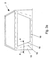
- Fig. 3a shows a part of the motor vehicle 2, namely the body shell of a motor vehicle 2 seen from the interior.
- an end wall frame 10 can be seen, which has in its interior an end wall opening in which the end wall module 1 is mounted.
- Fig. 3b is a section A-A is shown.
- the end wall module with its first wall 3a and its second wall 3b can be seen. Rib structures 4a and 4b and other components of the sandwich construction have already been explained above, so that reference is made to avoid repetition thereof.
- the end wall module is connected via screw 14 with a sheet metal structure 13 of the frame 10.
- the end wall module 1 is also connected over a large area to the sheet metal structure 13 via an adhesive layer, not shown.
- the second wall 3b projects beyond the first outer wall 3a at the lateral outer edges.
- the outer edge of the first wall is denoted by 15 (solid line in Fig. 3a) and the outer edge of the second wall by 12 (hatched line in Fig. 3a).
- the second wall surmounts the first wall by a total of 10%.
- the second wall has on its side facing away from the first wall 3a side an outer rib structure 9, which extends continuously from the common overlapping region of wall 3a and 3b (ie within the region 12 in Fig. 3a) to the edge region of the projecting portion of the wall 3b (ie within the hatched line 15 in Fig. 3a).
- a stiffening of the second wall is achieved, in particular in this projecting area, whereby it is achieved that the second wall can be modeled as a whole (ie on its total area) as a unitarily oscillating system.
- components 5 such as parts of an air conditioner are also fixed.
- the second wall 3b (analogous is also possible for the first wall 3a) to complain. Due to the rib structures 4b and 9 is thus achieved that the entire second wall is to be regarded as a kind of "single-mass oscillator". It is therefore no longer necessary, as in the case of motor vehicles according to the prior art, to occupy the entire area within the dashed line 12, for example with a heavy mat, and thus to cause unnecessary ballast.
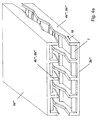
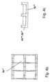
- FIGS. 4a to 4c show a further embodiment of an end wall module according to the invention.
- a first wall 3a "'with a first rib structure 8a"' with webs 4a "' is shown
- the second wall 3b"' has rib structures 4b "'with webs 8b"' between which are arranged at right angles stiffening webs 7, which, however never touch the opposite stiffening webs 7.
- the webs 4b '' have kinks in the course direction 18.
- FIG. 4b shows a plan view of the first wall 3b '
- FIG. 4c shows a side view of the first wall 3b' '.
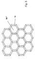
- Fig. 5 shows a plan view of a wall 3b "".
- the rib structures are formed as adjacent honeycomb 16.
- the honeycombs may also have a "chaotic" course, since in the uniform arrangement in Fig. 5 may cause acoustic problems.
- FIG. 6 shows a section through a honeycomb 16.
- recesses 17 are shown on the upper side of the honeycomb, which enable a better distribution of honeycomb to honeycomb during foaming.
- the attachment on the top is mainly for production reasons advantageous, in principle, corresponding recesses would be possible on the underside of the honeycomb webs.
- FIG. 7 shows another embodiment of a second wall 3b '''.
- These show mutually parallel webs 4b ""'of a rib structure 8b ""'.
- These webs have a zig-zag structure in the direction 18, ie in their direction of travel.
- This zigzag gradient which runs in the direction of a plane of the wall surface, also ensures that a better "thrust” is given, also with respect to bending advantages are achieved because the effective length of the webs based on the surface of the wall 3b ""'is longer and thus a better area moment of inertia is achieved, which is particularly important in bending in the frontal crash case.
- the end wall module according to the invention shown here offers an integrated very good sound insulation.
- This is not a construction of an end wall with an additional insulation arranged on it, it is particularly important that the insulation is already integrated.
- the two layers ie the first and the second wall
- Both walls in this case have a common voltage zero lying between the individual layers, resulting in an increased area moment of inertia, due to the increased spacing of the individual walls from the voltage zero line (Steiner proportion).
- the advantage of this variant lies in the possible smaller dimensioning of the end wall, wherein the total mass of the system is further reduced can be.
Landscapes
- Engineering & Computer Science (AREA)
- Mechanical Engineering (AREA)
- Chemical & Material Sciences (AREA)
- Combustion & Propulsion (AREA)
- Transportation (AREA)
- Structural Engineering (AREA)
- Architecture (AREA)
- Physics & Mathematics (AREA)
- Acoustics & Sound (AREA)
- Body Structure For Vehicles (AREA)
- Vehicle Interior And Exterior Ornaments, Soundproofing, And Insulation (AREA)
- Piezo-Electric Or Mechanical Vibrators, Or Delay Or Filter Circuits (AREA)
- Control Of Motors That Do Not Use Commutators (AREA)
Claims (18)
- Module de bout de caisse (1) pour un véhicule (2), le module de bout de caisse présentant une première paroi (3a) ainsi qu'une deuxième paroi (3b) à distance de celle-ci,
caractérisé en ce que la première paroi présente une première structure de nervures (4a) et la deuxième paroi une deuxième structure de nervures (4b), les structures de nervures étant formées de façon à ce que dans un état de montage non déformé du module de bout de caisse, la première et la deuxième structures de nervures sont à distance l'une de l'autre et dans au moins un état déformé du module de bout de caisse, les première et deuxième structures de nervures sont en prise l'une avec l'autre par complémentarité de formes. - Module de bout de caisse selon la revendication 1,
caractérisé en ce que, au niveau de la première (3a) et/ou la deuxième (3b) paroi, sur la face opposée à l'autre paroi respective, des composants comme des pièces de climatisation (5) ou similaires sont placés. - Module de bout de caisse selon l'une des revendications précédentes,
caractérisé en ce qu'entre la première (3a) et la deuxième (3b) paroi, de la mousse (7) est placée et/ou il existe un espace creux. - Module de bout de caisse selon l'une des revendications précédentes,
caractérisé en ce que la première (4a) et/ou la deuxième (4b) structure de nervures présente des traverses (8a, 8b). - Module de bout de caisse selon la revendication 4,
caractérisé en ce que la première (4a) et/ou la deuxième (4b) structure de nervures présente chacune une traverse (8a, 8b) de même longueur en direction de l'autre paroi respective. - Module de bout de caisse selon la revendication 4,
caractérisé en ce que la première (4a') et la deuxième (4b') structure de nervures présentent chacune une traverse (8a', 8b') de longueur différente en direction de l'autre paroi respective. - Module de bout de caisse selon l'une des revendications 4 à 6,
caractérisé en ce qu'entre les traverses (8a, 8b) d'une structure de nervures (4a, 4b) l'écart est situé entre 2 mm et 200 mm, de préférence entre 4 mm et 25 mm. - Module de bout de caisse selon l'une des revendications 4 à 7,
caractérisé en ce que les traverses (8a, 8b) de la première structure de nervures (4a) présentent une forme convexe ou concave sur leurs extrémités pointant vers la deuxième structure de nervures (4b). - Module de bout de caisse selon la revendication 4,
caractérisé en ce que la première structure de nervures (4a") présente des traverses et la deuxième structure de nervures (4b") des espaces creux (8b") pour recevoir ces traverses. - Module de bout de caisse selon l'une des revendications précédentes,
caractérisé en ce que la largeur de fente la plus mince entre la première (4a) et la deuxième (4b) structure de nervures est située entre 0,5 mm et 5,0 mm, de préférence entre 1 mm et 2 mm. - Module de bout de caisse selon l'une des revendications précédentes,
caractérisé en ce que la deuxième paroi (3b) du module de bout de caisse (1) dépasse de la première paroi (3a) latéralement au moins de manière localisée. - Module de bout de caisse selon la revendication 11,
caractérisé en ce que la surface de la deuxième paroi (3b) sur la face opposée à la première paroi (3a) présente au moins 10, de préférence 20, de manière particulièrement préférée 30% de surface de plus que la première paroi sur sa face opposée à la deuxième paroi. - Module de bout de caisse selon la revendication 11 ou 12,
caractérisé en ce que la deuxième paroi (3b) présente une structure de nervures extérieure dans des zones dépassant latéralement sur sa face opposée à la première paroi. - Module de bout de caisse selon l'une des revendications précédentes,
caractérisé en ce que la première (3a) et/ou la deuxième (3b) paroi et/ou les structures de nervures (4a, 4b) sont en plastique ou en métal. - Module de bout de caisse selon l'une des revendications 4 à 14,
caractérisé en ce les traverses (4a"', 4b"') présentent, sur leur face avant faisant face à la paroi respective, des courbures et/ou des coudes dans le sens de la marche. - Véhicule comprenant un module de bout de caisse (1) selon l'une des revendications précédentes.
- Véhicule selon la revendication 16,
caractérisé en ce que celui-ci comporte un cadre (10) pour enchâsser le module de bout de caisse (1). - Véhicule selon la revendication 17,
caractérisé en ce que le module de bout de caisse est vissé et/ou collé au cadre (10) pour l'enchâssement.
Priority Applications (1)
| Application Number | Priority Date | Filing Date | Title |
|---|---|---|---|
| SI200330415T SI1545962T1 (sl) | 2002-10-02 | 2003-10-02 | Celnostenski modul |
Applications Claiming Priority (3)
| Application Number | Priority Date | Filing Date | Title |
|---|---|---|---|
| DE10246994 | 2002-10-02 | ||
| DE10246994A DE10246994B3 (de) | 2002-10-02 | 2002-10-02 | Stirnwandmodul |
| PCT/EP2003/010957 WO2004056639A1 (fr) | 2002-10-02 | 2003-10-02 | Module de bout de caisse |
Publications (2)
| Publication Number | Publication Date |
|---|---|
| EP1545962A1 EP1545962A1 (fr) | 2005-06-29 |
| EP1545962B1 true EP1545962B1 (fr) | 2006-05-24 |
Family
ID=32102733
Family Applications (1)
| Application Number | Title | Priority Date | Filing Date |
|---|---|---|---|
| EP03813027A Expired - Lifetime EP1545962B1 (fr) | 2002-10-02 | 2003-10-02 | Module de bout de caisse |
Country Status (10)
| Country | Link |
|---|---|
| US (1) | US7497506B2 (fr) |
| EP (1) | EP1545962B1 (fr) |
| JP (1) | JP3949138B2 (fr) |
| CN (1) | CN100393568C (fr) |
| AT (1) | ATE327137T1 (fr) |
| AU (1) | AU2003303108A1 (fr) |
| BR (1) | BR0314974A (fr) |
| DE (2) | DE10246994B3 (fr) |
| ES (1) | ES2264039T3 (fr) |
| WO (1) | WO2004056639A1 (fr) |
Cited By (1)
| Publication number | Priority date | Publication date | Assignee | Title |
|---|---|---|---|---|
| DE102018211876A1 (de) * | 2018-07-17 | 2020-01-23 | Bayerische Motoren Werke Aktiengesellschaft | Fahrzeug-Exterieur-Komponente |
Families Citing this family (11)
| Publication number | Priority date | Publication date | Assignee | Title |
|---|---|---|---|---|
| FR2870818B1 (fr) * | 2004-05-27 | 2007-09-28 | Renault Sas | Ensemble de cockpit comprenant une structure resistante assemblee par collage |
| KR100662101B1 (ko) * | 2005-01-06 | 2006-12-27 | 주식회사 엘지화학 | 플라스틱제 판넬 |
| DE102005013635B4 (de) * | 2005-03-24 | 2020-11-26 | Volkswagen Ag | Verstärkungsrippen für Träger, insbesondere für Frontendmontageträger von Kraftfahrzeugen, sowie Spritzgießwerkzeug zur Herstellung der Verstärkungsrippen |
| US20080281734A1 (en) * | 2005-07-11 | 2008-11-13 | Appone Services, Inc. | System and method for integrated credit application and tax refund estimation |
| KR100906005B1 (ko) * | 2008-06-26 | 2009-07-06 | 엔브이에이치코리아(주) | 충격흡수부재 |
| DE102011081710B4 (de) | 2011-08-29 | 2022-11-17 | Robert Bosch Gmbh | Schutzvorrichtung zum Schutz einer Traktionsbatterie von Hybrid- oder Elektrofahrzeugen |
| DE102013216191B4 (de) * | 2013-08-14 | 2021-10-21 | Faurecia Innenraum Systeme Gmbh | Verfahren zur Herstellung eines Trägerelements und Trägerelement für ein Transportmittel |
| DE102013113210A1 (de) * | 2013-11-29 | 2015-06-18 | Connova Ag | Wärmeschutzvorrichtung für ein Kraftfahrzeug |
| DE102013113230A1 (de) * | 2013-11-29 | 2015-06-03 | Thyssenkrupp Steel Europe Ag | Verfahren zur Herstellung eines Außenverkleidungsteils für ein bewegbares Karosserieteil sowie ein entsprechendes Außenverkleidungsteil |
| JP6206303B2 (ja) * | 2014-04-07 | 2017-10-04 | マツダ株式会社 | 車両用フレーム構造 |
| EP3431345B1 (fr) * | 2017-07-20 | 2020-04-01 | Faurecia Interior Systems India Pvt. Ltd. | Absorbeur d'énergie d'impact pour véhicule |
Family Cites Families (18)
| Publication number | Priority date | Publication date | Assignee | Title |
|---|---|---|---|---|
| US3933387A (en) * | 1975-03-10 | 1976-01-20 | General Motors Corporation | Thermoformed plastic energy absorber for vehicles |
| US4555134A (en) * | 1983-07-20 | 1985-11-26 | Leo Gruna | Crush resistant motor vehicle body |
| EP0744281B1 (fr) * | 1995-05-24 | 2001-07-11 | SAI Automotive Sommer Industrie | Produit insonorisant avec absorbeur d'énergie intégré et procédé pour son obtention |
| JP3532678B2 (ja) | 1995-10-03 | 2004-05-31 | 本田技研工業株式会社 | エンジンルームと車室間の隔壁 |
| WO1998018656A1 (fr) * | 1996-10-29 | 1998-05-07 | Rieter Automotive (International) Ag | Assemblage de materiaux ultraleger, multifonctionnel et insonorisant |
| JP3867332B2 (ja) | 1997-01-29 | 2007-01-10 | トヨタ車体株式会社 | 車両における衝撃吸収樹脂リブ構造 |
| US5934729A (en) * | 1997-03-10 | 1999-08-10 | Ford Global Technologies, Inc. | Energy-absorbing fastener system |
| US6752450B2 (en) * | 1998-02-04 | 2004-06-22 | Oakwood Energy Management, Inc. | Formed energy absorber |
| DE19946655A1 (de) | 1999-09-29 | 2001-04-12 | Cww Gerko Akustik Gmbh & Co Kg | Stirnwandisolation |
| JP3330921B2 (ja) * | 2000-03-13 | 2002-10-07 | 菊池プレス工業株式会社 | テーラードブランク製物品及びその製造方法 |
| US7052077B1 (en) * | 2000-06-13 | 2006-05-30 | Meritor Light Vehicle Systems, Inc. | Crumple zone for body panels |
| DE10143564A1 (de) * | 2001-09-05 | 2003-03-20 | Basf Ag | Hohlprofilverbundbauteile |
| DE10145641A1 (de) | 2001-09-15 | 2003-04-10 | Krauss Maffei Wegmann Gmbh & C | Verfahren zur Erfassung einer Luftlage in einem Kampffahrzeug sowie Vorrichtung zur Durchführung des Verfahrens |
| DE10154593A1 (de) * | 2001-11-07 | 2003-05-15 | Arvinmeritor Gmbh | Deformationselement, insbesondere für Kraftfahrzeuge |
| US7216926B2 (en) * | 2003-10-22 | 2007-05-15 | Hampel Lance T | Vehicle cab |
| US6988761B1 (en) * | 2004-02-23 | 2006-01-24 | Brian Stidham | Interlocking channeled trailer side panels with integrated sliding outer panel inserts |
| JP4531468B2 (ja) * | 2004-07-14 | 2010-08-25 | 小島プレス工業株式会社 | 車両用衝撃吸収構造体及びその取付構造 |
| US7201434B1 (en) * | 2005-11-04 | 2007-04-10 | Cadence Innovation Llc | Energy-absorbing bolster for an automotive instrument panel assembly |
-
2002
- 2002-10-02 DE DE10246994A patent/DE10246994B3/de not_active Expired - Fee Related
-
2003
- 2003-10-02 EP EP03813027A patent/EP1545962B1/fr not_active Expired - Lifetime
- 2003-10-02 BR BR0314974-9A patent/BR0314974A/pt not_active IP Right Cessation
- 2003-10-02 DE DE50303503T patent/DE50303503D1/de not_active Expired - Lifetime
- 2003-10-02 US US10/530,097 patent/US7497506B2/en not_active Expired - Fee Related
- 2003-10-02 WO PCT/EP2003/010957 patent/WO2004056639A1/fr active IP Right Grant
- 2003-10-02 ES ES03813027T patent/ES2264039T3/es not_active Expired - Lifetime
- 2003-10-02 AT AT03813027T patent/ATE327137T1/de not_active IP Right Cessation
- 2003-10-02 CN CNB2003801008566A patent/CN100393568C/zh not_active Expired - Fee Related
- 2003-10-02 AU AU2003303108A patent/AU2003303108A1/en not_active Abandoned
- 2003-10-02 JP JP2004561135A patent/JP3949138B2/ja not_active Expired - Fee Related
Cited By (1)
| Publication number | Priority date | Publication date | Assignee | Title |
|---|---|---|---|---|
| DE102018211876A1 (de) * | 2018-07-17 | 2020-01-23 | Bayerische Motoren Werke Aktiengesellschaft | Fahrzeug-Exterieur-Komponente |
Also Published As
| Publication number | Publication date |
|---|---|
| ES2264039T3 (es) | 2006-12-16 |
| DE50303503D1 (de) | 2006-06-29 |
| CN1703345A (zh) | 2005-11-30 |
| CN100393568C (zh) | 2008-06-11 |
| WO2004056639A1 (fr) | 2004-07-08 |
| JP3949138B2 (ja) | 2007-07-25 |
| US20060162278A1 (en) | 2006-07-27 |
| AU2003303108A1 (en) | 2004-07-14 |
| BR0314974A (pt) | 2005-08-02 |
| JP2006502047A (ja) | 2006-01-19 |
| ATE327137T1 (de) | 2006-06-15 |
| US7497506B2 (en) | 2009-03-03 |
| EP1545962A1 (fr) | 2005-06-29 |
| DE10246994B3 (de) | 2004-05-13 |
Similar Documents
| Publication | Publication Date | Title |
|---|---|---|
| DE60109869T2 (de) | Verkleidungsteil für die Unterseite eines Motors mit verbesserter Festigkeit | |
| DE102016122663A1 (de) | Aufprallabsorptionseinheit, Herstellungsverfahren davon und Elementverbindungsstruktur | |
| DE102017104360A1 (de) | Batteriegehäuse | |
| DE4332166A1 (de) | Energieabsorbierende Fahrzeugtür | |
| EP1545962B1 (fr) | Module de bout de caisse | |
| DE10053840A1 (de) | Stoßfängersystem für Fahrzeuge | |
| DE102006001061A1 (de) | Kraftfahrzeug mit wenigstens einem längsseitig an seiner Karosserie verlaufenden, verstärkten Türschweller | |
| DE112015001441T5 (de) | Fahrzeugenergie-Absorptionsstruktur und Energieabsorptionselement | |
| WO2005123459A1 (fr) | Composant pour l'absorption d'energie lors d'un choc | |
| DE10003878A1 (de) | Zusatzelement | |
| EP2571747A1 (fr) | Véhicule à moteur pourvu d'un bas de marche latéral | |
| DE60210220T2 (de) | Doppelwandige Dämpfungsstruktur | |
| EP3953602A1 (fr) | Élément de flexion constitué d'un matériau composite plastique fibreux | |
| DE202007016671U1 (de) | Energieabsorber zur Verwendung als Aufprallschutz in einem Kraftfahrzeug | |
| EP1925488B1 (fr) | Tableau de bord et son procédé de fabrication | |
| DE102013002504A1 (de) | Kraftfahrzeug-Bodenstruktur | |
| DE102013002537A1 (de) | Schweller-Bodenstruktur-Anordnung | |
| DE102019132450A1 (de) | Batteriegehäuse für ein elektromotorisch angetriebenes Fahrzeug | |
| DE69714465T2 (de) | Omnibus mit sicherheitsvorrichtungen wie eine überrollvorrichtung, sowie verfahren zum zusammenbau eines omnibuses | |
| EP2239128A1 (fr) | Pièce de véhicule dotée d'un élément de renforcement de structure | |
| EP4055297B1 (fr) | Élément de ressort à flexion ayant un material renforcé de fibres | |
| EP3348457A1 (fr) | Appui de renforcement pour un véhicule automobile | |
| EP2335982B1 (fr) | Elément d'absorbeur pour un véhicule automobile | |
| EP0943531A2 (fr) | Structure de caisse de véhicule automobile | |
| DE10232321B4 (de) | Stoßfängerträger für ein Fahrzeug |
Legal Events
| Date | Code | Title | Description |
|---|---|---|---|
| PUAI | Public reference made under article 153(3) epc to a published international application that has entered the european phase |
Free format text: ORIGINAL CODE: 0009012 |
|
| 17P | Request for examination filed |
Effective date: 20050315 |
|
| AK | Designated contracting states |
Kind code of ref document: A1 Designated state(s): AT BE BG CH CY CZ DE DK EE ES FI FR GB GR HU IE IT LI LU MC NL PT RO SE SI SK TR |
|
| AX | Request for extension of the european patent |
Extension state: AL LT LV MK |
|
| GRAP | Despatch of communication of intention to grant a patent |
Free format text: ORIGINAL CODE: EPIDOSNIGR1 |
|
| DAX | Request for extension of the european patent (deleted) | ||
| GRAS | Grant fee paid |
Free format text: ORIGINAL CODE: EPIDOSNIGR3 |
|
| GRAA | (expected) grant |
Free format text: ORIGINAL CODE: 0009210 |
|
| AK | Designated contracting states |
Kind code of ref document: B1 Designated state(s): AT BE BG CH CY CZ DE DK EE ES FI FR GB GR HU IE IT LI LU MC NL PT RO SE SI SK TR |
|
| PG25 | Lapsed in a contracting state [announced via postgrant information from national office to epo] |
Ref country code: IT Free format text: LAPSE BECAUSE OF FAILURE TO SUBMIT A TRANSLATION OF THE DESCRIPTION OR TO PAY THE FEE WITHIN THE PRESCRIBED TIME-LIMIT;WARNING: LAPSES OF ITALIAN PATENTS WITH EFFECTIVE DATE BEFORE 2007 MAY HAVE OCCURRED AT ANY TIME BEFORE 2007. THE CORRECT EFFECTIVE DATE MAY BE DIFFERENT FROM THE ONE RECORDED. Effective date: 20060524 Ref country code: NL Free format text: LAPSE BECAUSE OF FAILURE TO SUBMIT A TRANSLATION OF THE DESCRIPTION OR TO PAY THE FEE WITHIN THE PRESCRIBED TIME-LIMIT Effective date: 20060524 Ref country code: GB Free format text: LAPSE BECAUSE OF FAILURE TO SUBMIT A TRANSLATION OF THE DESCRIPTION OR TO PAY THE FEE WITHIN THE PRESCRIBED TIME-LIMIT Effective date: 20060524 Ref country code: SK Free format text: LAPSE BECAUSE OF FAILURE TO SUBMIT A TRANSLATION OF THE DESCRIPTION OR TO PAY THE FEE WITHIN THE PRESCRIBED TIME-LIMIT Effective date: 20060524 Ref country code: FI Free format text: LAPSE BECAUSE OF FAILURE TO SUBMIT A TRANSLATION OF THE DESCRIPTION OR TO PAY THE FEE WITHIN THE PRESCRIBED TIME-LIMIT Effective date: 20060524 Ref country code: IE Free format text: LAPSE BECAUSE OF FAILURE TO SUBMIT A TRANSLATION OF THE DESCRIPTION OR TO PAY THE FEE WITHIN THE PRESCRIBED TIME-LIMIT Effective date: 20060524 |
|
| REG | Reference to a national code |
Ref country code: GB Ref legal event code: FG4D Free format text: NOT ENGLISH |
|
| REG | Reference to a national code |
Ref country code: CH Ref legal event code: EP |
|
| REG | Reference to a national code |
Ref country code: IE Ref legal event code: FG4D Free format text: LANGUAGE OF EP DOCUMENT: GERMAN |
|
| REF | Corresponds to: |
Ref document number: 50303503 Country of ref document: DE Date of ref document: 20060629 Kind code of ref document: P |
|
| REG | Reference to a national code |
Ref country code: RO Ref legal event code: EPE |
|
| PG25 | Lapsed in a contracting state [announced via postgrant information from national office to epo] |
Ref country code: DK Free format text: LAPSE BECAUSE OF FAILURE TO SUBMIT A TRANSLATION OF THE DESCRIPTION OR TO PAY THE FEE WITHIN THE PRESCRIBED TIME-LIMIT Effective date: 20060824 |
|
| REG | Reference to a national code |
Ref country code: SE Ref legal event code: TRGR |
|
| PG25 | Lapsed in a contracting state [announced via postgrant information from national office to epo] |
Ref country code: PT Free format text: LAPSE BECAUSE OF FAILURE TO SUBMIT A TRANSLATION OF THE DESCRIPTION OR TO PAY THE FEE WITHIN THE PRESCRIBED TIME-LIMIT Effective date: 20061024 |
|
| PG25 | Lapsed in a contracting state [announced via postgrant information from national office to epo] |
Ref country code: MC Free format text: LAPSE BECAUSE OF NON-PAYMENT OF DUE FEES Effective date: 20061031 |
|
| NLV1 | Nl: lapsed or annulled due to failure to fulfill the requirements of art. 29p and 29m of the patents act | ||
| REG | Reference to a national code |
Ref country code: ES Ref legal event code: FG2A Ref document number: 2264039 Country of ref document: ES Kind code of ref document: T3 |
|
| GBV | Gb: ep patent (uk) treated as always having been void in accordance with gb section 77(7)/1977 [no translation filed] |
Effective date: 20060524 |
|
| ET | Fr: translation filed | ||
| REG | Reference to a national code |
Ref country code: IE Ref legal event code: FD4D |
|
| PLBE | No opposition filed within time limit |
Free format text: ORIGINAL CODE: 0009261 |
|
| STAA | Information on the status of an ep patent application or granted ep patent |
Free format text: STATUS: NO OPPOSITION FILED WITHIN TIME LIMIT |
|
| 26N | No opposition filed |
Effective date: 20070227 |
|
| BERE | Be: lapsed |
Owner name: FAURECIA INNENRAUM SYSTEME G.M.B.H. Effective date: 20061031 |
|
| PG25 | Lapsed in a contracting state [announced via postgrant information from national office to epo] |
Ref country code: AT Free format text: LAPSE BECAUSE OF NON-PAYMENT OF DUE FEES Effective date: 20061002 |
|
| PG25 | Lapsed in a contracting state [announced via postgrant information from national office to epo] |
Ref country code: GR Free format text: LAPSE BECAUSE OF FAILURE TO SUBMIT A TRANSLATION OF THE DESCRIPTION OR TO PAY THE FEE WITHIN THE PRESCRIBED TIME-LIMIT Effective date: 20060825 |
|
| REG | Reference to a national code |
Ref country code: CH Ref legal event code: PL |
|
| PG25 | Lapsed in a contracting state [announced via postgrant information from national office to epo] |
Ref country code: BG Free format text: LAPSE BECAUSE OF FAILURE TO SUBMIT A TRANSLATION OF THE DESCRIPTION OR TO PAY THE FEE WITHIN THE PRESCRIBED TIME-LIMIT Effective date: 20060824 Ref country code: EE Free format text: LAPSE BECAUSE OF FAILURE TO SUBMIT A TRANSLATION OF THE DESCRIPTION OR TO PAY THE FEE WITHIN THE PRESCRIBED TIME-LIMIT Effective date: 20060524 |
|
| PG25 | Lapsed in a contracting state [announced via postgrant information from national office to epo] |
Ref country code: LU Free format text: LAPSE BECAUSE OF NON-PAYMENT OF DUE FEES Effective date: 20061002 Ref country code: HU Free format text: LAPSE BECAUSE OF FAILURE TO SUBMIT A TRANSLATION OF THE DESCRIPTION OR TO PAY THE FEE WITHIN THE PRESCRIBED TIME-LIMIT Effective date: 20061125 Ref country code: CH Free format text: LAPSE BECAUSE OF NON-PAYMENT OF DUE FEES Effective date: 20071031 Ref country code: LI Free format text: LAPSE BECAUSE OF NON-PAYMENT OF DUE FEES Effective date: 20071031 |
|
| PG25 | Lapsed in a contracting state [announced via postgrant information from national office to epo] |
Ref country code: CY Free format text: LAPSE BECAUSE OF FAILURE TO SUBMIT A TRANSLATION OF THE DESCRIPTION OR TO PAY THE FEE WITHIN THE PRESCRIBED TIME-LIMIT Effective date: 20060524 |
|
| PGFP | Annual fee paid to national office [announced via postgrant information from national office to epo] |
Ref country code: CZ Payment date: 20080922 Year of fee payment: 6 |
|
| PGFP | Annual fee paid to national office [announced via postgrant information from national office to epo] |
Ref country code: TR Payment date: 20081003 Year of fee payment: 6 |
|
| PGFP | Annual fee paid to national office [announced via postgrant information from national office to epo] |
Ref country code: ES Payment date: 20081015 Year of fee payment: 6 Ref country code: RO Payment date: 20081002 Year of fee payment: 6 |
|
| PGFP | Annual fee paid to national office [announced via postgrant information from national office to epo] |
Ref country code: SE Payment date: 20081023 Year of fee payment: 6 Ref country code: IT Payment date: 20081022 Year of fee payment: 6 |
|
| PGFP | Annual fee paid to national office [announced via postgrant information from national office to epo] |
Ref country code: SI Payment date: 20070918 Year of fee payment: 6 |
|
| PG25 | Lapsed in a contracting state [announced via postgrant information from national office to epo] |
Ref country code: BE Free format text: LAPSE BECAUSE OF FAILURE TO SUBMIT A TRANSLATION OF THE DESCRIPTION OR TO PAY THE FEE WITHIN THE PRESCRIBED TIME-LIMIT Effective date: 20061031 |
|
| EUG | Se: european patent has lapsed | ||
| REG | Reference to a national code |
Ref country code: SI Ref legal event code: KO00 Effective date: 20100602 |
|
| PG25 | Lapsed in a contracting state [announced via postgrant information from national office to epo] |
Ref country code: SI Free format text: LAPSE BECAUSE OF NON-PAYMENT OF DUE FEES Effective date: 20091003 Ref country code: CZ Free format text: LAPSE BECAUSE OF NON-PAYMENT OF DUE FEES Effective date: 20091002 |
|
| PG25 | Lapsed in a contracting state [announced via postgrant information from national office to epo] |
Ref country code: RO Free format text: LAPSE BECAUSE OF NON-PAYMENT OF DUE FEES Effective date: 20091002 |
|
| REG | Reference to a national code |
Ref country code: ES Ref legal event code: FD2A Effective date: 20110323 |
|
| PG25 | Lapsed in a contracting state [announced via postgrant information from national office to epo] |
Ref country code: IT Free format text: LAPSE BECAUSE OF NON-PAYMENT OF DUE FEES Effective date: 20091002 |
|
| PG25 | Lapsed in a contracting state [announced via postgrant information from national office to epo] |
Ref country code: SE Free format text: LAPSE BECAUSE OF NON-PAYMENT OF DUE FEES Effective date: 20091003 |
|
| PG25 | Lapsed in a contracting state [announced via postgrant information from national office to epo] |
Ref country code: ES Free format text: LAPSE BECAUSE OF NON-PAYMENT OF DUE FEES Effective date: 20110310 |
|
| PG25 | Lapsed in a contracting state [announced via postgrant information from national office to epo] |
Ref country code: ES Free format text: LAPSE BECAUSE OF NON-PAYMENT OF DUE FEES Effective date: 20091003 |
|
| PG25 | Lapsed in a contracting state [announced via postgrant information from national office to epo] |
Ref country code: TR Free format text: LAPSE BECAUSE OF NON-PAYMENT OF DUE FEES Effective date: 20091002 |
|
| PGFP | Annual fee paid to national office [announced via postgrant information from national office to epo] |
Ref country code: DE Payment date: 20130920 Year of fee payment: 11 Ref country code: FR Payment date: 20131028 Year of fee payment: 11 |
|
| REG | Reference to a national code |
Ref country code: DE Ref legal event code: R119 Ref document number: 50303503 Country of ref document: DE |
|
| PG25 | Lapsed in a contracting state [announced via postgrant information from national office to epo] |
Ref country code: DE Free format text: LAPSE BECAUSE OF NON-PAYMENT OF DUE FEES Effective date: 20150501 |
|
| REG | Reference to a national code |
Ref country code: FR Ref legal event code: ST Effective date: 20150630 |
|
| PG25 | Lapsed in a contracting state [announced via postgrant information from national office to epo] |
Ref country code: FR Free format text: LAPSE BECAUSE OF NON-PAYMENT OF DUE FEES Effective date: 20141031 |