EP1545962B1 - Stirnwandmodul - Google Patents
Stirnwandmodul Download PDFInfo
- Publication number
- EP1545962B1 EP1545962B1 EP03813027A EP03813027A EP1545962B1 EP 1545962 B1 EP1545962 B1 EP 1545962B1 EP 03813027 A EP03813027 A EP 03813027A EP 03813027 A EP03813027 A EP 03813027A EP 1545962 B1 EP1545962 B1 EP 1545962B1
- Authority
- EP
- European Patent Office
- Prior art keywords
- wall
- webs
- wall module
- rib structure
- module according
- Prior art date
- Legal status (The legal status is an assumption and is not a legal conclusion. Google has not performed a legal analysis and makes no representation as to the accuracy of the status listed.)
- Expired - Lifetime
Links
Images


Classifications
-
- B—PERFORMING OPERATIONS; TRANSPORTING
- B62—LAND VEHICLES FOR TRAVELLING OTHERWISE THAN ON RAILS
- B62D—MOTOR VEHICLES; TRAILERS
- B62D29/00—Superstructures, understructures, or sub-units thereof, characterised by the material thereof
- B62D29/001—Superstructures, understructures, or sub-units thereof, characterised by the material thereof characterised by combining metal and synthetic material
-
- B—PERFORMING OPERATIONS; TRANSPORTING
- B60—VEHICLES IN GENERAL
- B60R—VEHICLES, VEHICLE FITTINGS, OR VEHICLE PARTS, NOT OTHERWISE PROVIDED FOR
- B60R13/00—Elements for body-finishing, identifying, or decorating; Arrangements or adaptations for advertising purposes
- B60R13/08—Insulating elements, e.g. for sound insulation
- B60R13/0815—Acoustic or thermal insulation of passenger compartments
- B60R13/083—Acoustic or thermal insulation of passenger compartments for fire walls or floors
-
- B—PERFORMING OPERATIONS; TRANSPORTING
- B62—LAND VEHICLES FOR TRAVELLING OTHERWISE THAN ON RAILS
- B62D—MOTOR VEHICLES; TRAILERS
- B62D25/00—Superstructure or monocoque structure sub-units; Parts or details thereof not otherwise provided for
- B62D25/08—Front or rear portions
- B62D25/14—Dashboards as superstructure sub-units
-
- B—PERFORMING OPERATIONS; TRANSPORTING
- B62—LAND VEHICLES FOR TRAVELLING OTHERWISE THAN ON RAILS
- B62D—MOTOR VEHICLES; TRAILERS
- B62D29/00—Superstructures, understructures, or sub-units thereof, characterised by the material thereof
- B62D29/001—Superstructures, understructures, or sub-units thereof, characterised by the material thereof characterised by combining metal and synthetic material
- B62D29/002—Superstructures, understructures, or sub-units thereof, characterised by the material thereof characterised by combining metal and synthetic material a foamable synthetic material or metal being added in situ
-
- B—PERFORMING OPERATIONS; TRANSPORTING
- B62—LAND VEHICLES FOR TRAVELLING OTHERWISE THAN ON RAILS
- B62D—MOTOR VEHICLES; TRAILERS
- B62D29/00—Superstructures, understructures, or sub-units thereof, characterised by the material thereof
- B62D29/001—Superstructures, understructures, or sub-units thereof, characterised by the material thereof characterised by combining metal and synthetic material
- B62D29/004—Superstructures, understructures, or sub-units thereof, characterised by the material thereof characterised by combining metal and synthetic material the metal being over-moulded by the synthetic material, e.g. in a mould
-
- B—PERFORMING OPERATIONS; TRANSPORTING
- B62—LAND VEHICLES FOR TRAVELLING OTHERWISE THAN ON RAILS
- B62D—MOTOR VEHICLES; TRAILERS
- B62D29/00—Superstructures, understructures, or sub-units thereof, characterised by the material thereof
- B62D29/001—Superstructures, understructures, or sub-units thereof, characterised by the material thereof characterised by combining metal and synthetic material
- B62D29/005—Superstructures, understructures, or sub-units thereof, characterised by the material thereof characterised by combining metal and synthetic material preformed metal and synthetic material elements being joined together, e.g. by adhesives
Definitions
- the present invention relates to an end wall module for a motor vehicle according to the preamble of claim 1.
- End wall modules for motor vehicles are known in principle.
- the main function of such a bulkhead module is the separation of the engine compartment from the vehicle interior in motor vehicles.
- This bulkhead module must meet special requirements especially in modern high-quality motor vehicles. This includes on the one hand a good sound insulation from the engine compartment to the vehicle interior and also the best possible stiffening of the body to reduce torsional vibrations about the vehicle longitudinal axis. Despite these requirements, the bulkhead module should have only a low weight.
- end wall modules or end walls which at least partially have a sandwich structure. That is, a first and spaced therefrom a second wall is provided. These walls are connected by a relatively "hard” foam layer.
- the present invention is therefore an object of the invention to provide a bulkhead module for motor vehicles, which on the one hand is lightweight and on the other hand, both very good sound insulation properties and, especially in the event of a crash, high security.
- a generic end wall module on the first wall has a first rib structure and on the second wall, a second rib structure, wherein the rib structures are shaped so that in an undeformed state of installation of the end wall module, the first and second rib structure are spaced from each other (ie not directly in Are engaged) and in at least one deformed state of the bulkhead module (eg in the case of a frontal crash at Deflection of the end wall module) first and second rib structures are positively engaged with each other, this object is achieved.
- a structure-borne sound transmission via the rib structures is thus prevented due to their spacing, the airborne sound transmission is interrupted by the existing cavity between the two walls.
- the double wall on the one hand a good sound attenuation and sound insulation is effected (with sufficient torsional strength) and beyond in the event of a crash due to the engagement of the rib structures, the area moments of inertia, especially in bending increase sharply, so that penetration of components of the Engine compartment can be prevented in the vehicle interior.
- a development of the end wall module provides that components such as air conditioning parts or the like are arranged on the first and / or second wall on the side facing away from the other wall side. As a result, mass is applied to the wall, so that the wall swings together with these components as a kind of "spring-mass system". Due to the rib structures, which also increase the flexural rigidity of the corresponding wall, the wall is stiffened so that bending vibrations within the wall itself can not occur. By the rib structures is thus ensured that the entire wall (or a desired part) as a "unit” oscillates, thereby the mass of the coupled component is quasi “acoustically effective". It is particularly advantageous if the weight of the attached components is greater than 2 kg / m 2 basis weight.
- the entire end wall can be regarded as a spring-mass system and is therefore less susceptible to originating from the engine compartment vibrations.
- a so-called “heavy mat” (with 3.5 to 6 kg / m 2 ) can be saved, whose only task is to increase the acoustically effective mass, which on the other hand, however, due to their otherwise unnecessary ballast consumption values of Motor vehicles increased.
- a further advantageous embodiment provides that in the space between the first and second wall foam (such as polyurethane foam) is arranged or a cavity exists.
- foam such as polyurethane foam
- the airborne sound transmission is reduced to a minimum. Due to the lack of connection of the rib structures to each other, the structure-borne sound transmission is also reduced.
- the foam can either fill the entire space (in this case, a relatively "soft foam" should be selected to keep the structure-borne sound transmission low.
- first and / or second rib structure comprises webs.
- These webs can either be "rod-shaped" and be directed straight to the other wall. It is better, however, if these webs (for example of constant cross-section) e.g. standing vertically standing over a greater length on the first and second wall. This ensures that these rib structures on the one hand cause an increase in the rigidity of the walls. In addition, the webs do not vibrate with respect to the wall, so that no additional sound sources arise.
- the first rib structure always has ridges of equal length (i.e., toward the second wall in the spatial direction).
- the webs run virtually "to the center line", thus the stiffness of both walls are relatively equal to make high.
- first rib structure prefferably has webs each with a different length in the direction of the second wall. This ensures that, for example, facilitates the insertion of a "foam curve" in the production of the bulkhead module becomes.
- this "gearing" which is given complementarily on the opposite wall, with shear stress of the end wall module ensures even greater stability.
- a particularly advantageous development provides that the distance between the webs of a rib structure is between 2 mm to 200 mm, preferably 4 mm to 25 mm.
- Another particularly advantageous embodiment provides that the webs on their facing the respective opposite wall surface (ie, their end face) in their course direction curvatures and / or kinks.
- bends or curvatures may be arranged in a spatial direction parallel to the wall surface plane on which the web stands (for example a zigzag course of the webs).
- the kinks or curvature are so complementary that a positive fit of the opposite rib structures is given corresponding deformation.
- the webs of the first rib structure prefferably have a concave or convex shape at their ends pointing to the second rib structure
- the webs complementary thereto have a corresponding complementary structure.
- the ends of the webs can be designed either tapering in cross-section (eg in the triangular cross-section) or with a spherical cross-section.
- first rib structure webs and the second rib structure has cavities for receiving these webs.
- the rib structures are constructed as a kind of "trigger".
- a first rib structure presses into the opposite rib structure, which e.g. has a cavity centrally to the respective wall out.
- a fin structure equipped with webs can dip into the cavity of the opposite rib structure and absorb energy in the process.
- the webs with respect to the corresponding cavities have a slight lateral excess, so that friction work is performed upon insertion into the cavities, which consumes crash energy.
- the inner sides of the cavities or the outer sides of the webs can be equipped with a rough surface (micro latching) or with corresponding larger locking elements. This ensures that after complete penetration of the webs into the cavities, a particularly strong composite of both walls is formed, which is insoluble and whose area moment of inertia due to the Unverschiebles the walls to each other is particularly high.
- a further advantageous embodiment provides that the smallest gap width between the first and second rib structure is between 0.5 and 5 mm, preferably 1 mm to 2 mm. This ensures that the structure-borne noise between the first and second walls, even with slight vibrations of the first or second wall is not transmitted.
- a further advantageous embodiment provides that the surface of the second wall on the side facing away from the first wall at least 10, preferably 20, more preferably 30% more surface than the first wall on its side facing away from the second wall side.
- the end wall module is inserted into a frame for enclosing the end wall module, which is provided in a motor vehicle body.
- the end wall module is at least one direction (eg from the vehicle interior) to insert easily in the end wall frame, the surface excess of the second wall here on the one hand due to the contact surface with the end wall frame for a particularly good strength (this can be increased in particular in that the end wall frame is glued to the end wall module and additionally screwed in place).
- additional stiffening ribs are given. This ensures that the high acoustic mass of the second wall is effective into the edge region of the second wall.
- first and / or second wall and / or the rib structures are made of plastic or metal (in this case, materials should be provided which are temperature-resistant at over 140 ° C.). It is advantageous if wall and rib structures are in one piece, this allows eg a more favorable position by injection molding. Of course, two-part versions are possible. As materials Come metals or especially plastics into consideration. Suitable plastics are polypropylene, polyesters (such as' PET, PBT) polyamide or polyethylene, all with 30 to 50 wt .-% glass fiber content. Correspondingly, carbon fibers or aramid fibers can also be added.
- the wall thickness of the first or second wall in the case of plastic is preferably 1 to 6 mm, particularly preferably 3 mm.
- the modulus of elasticity is 8000 to 12000 Mega Pascal.
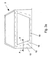
- Fig. 1a shows a section of a cross section through an end wall module 1 for a motor vehicle.
- the end wall module has a first wall 3a and spaced therefrom a second wall 3b.
- the first wall 3a has a rib structure 4a.
- the second wall 3b has a second rib structure 4b.
- the first rib structure 4a has webs 8a which extend in the direction perpendicular to the plane of the drawing in length.
- the first rib structure also has intersecting stiffening webs 7 on the first wall 3a.
- the webs 8a have triangular tips at their end facing the second wall 3b.
- the second wall 3b also has webs 8b which belong to the second rib structure 4b and likewise stiffening webs 7 crossing therewith.
- These webs 8b have at their end pointing to the first wall 3a a complementary shape to the tips of the webs 8a, likewise triangular in cross-section on, in the form of a bulge.
- a gap is provided which is at least between 0.5 mm and 5 mm in size.
- the end wall module in Fig. 1a also shows foam areas 6. This is a polyurethane foam.
- the area between the first and second walls can also be partially used be evacuated.
- the end wall module of Figure 1a is an end wall module having first and second walls and respective rib structures, wherein the rib structures are shaped such that in the undeformed mounting state of the end wall module shown in Figure 1a, the first and second rib structures are spaced apart , It will be discussed later (see Fig. 2), as in bending load of the end wall module, the opposite webs 8a and 8b of the rib structures engage each other.
- the distance between the individual webs 8a is, as indicated in FIG. 1a with x1, between 3 and 6 mm.
- Fig. 1b shows an alternative embodiment of a bulkhead module 1 '.
- a first wall 3a 'and a second wall 3b' is shown.
- the webs 8a 'of the first rib structure 4a' in the direction perpendicular to the surface plane of the first wall 3a 'do not have the same length, but the webs have different web lengths, here in alternating alternation.
- the first and second rib structures each have webs with in the direction of the respective other wall of the same length.
- the first and second rib structures respectively Bridges with in the direction of the other wall of different lengths.
- FIG. 1c shows a further embodiment 1 "of an end wall module according to the invention, which again has a first wall 3a” and a second wall 3b ".
- the first wall 3a” has a first rib structure 4a "with webs 8a”.
- the second wall 3b has a rib structure 4b".
- the second rib structure 4b “has cavities 8b" for receiving the webs 8a ", or the webs 8a” or the ends of the border of the cavities 8b "facing the webs can have inlet bevels
- the cavities 8b" are at a smaller distance from one another than the webs Width of the webs 8a ", so that in the case of penetration of the webs 8a" into the cavities 8b "is performed due to the deformation work deformation, which absorbs crash energy.
- the corresponding surfaces can each have a rough surface to ensure micro-locking or with corresponding Locking lugs are provided which prevent separation of the first wall 3a "and 3b".
- Fig. 2 shows the end wall module according to Fig. 1a in a deformed state.
- a bending force F By applying a bending force F, there is a deflection of the bulkhead module 1, as would be the case in the case of a frontal collision of the motor vehicle.
- the rib structures 4a and 4b engage with their webs 8a and 8b with each other.
- the flexural rigidity of the bulkhead module is drastically increased, thereby allowing penetration of engine compartment components Can be prevented in the vehicle interior.
- All end wall modules shown in the figures have first and second walls made of plastic. Wall and rib structure each form a single part, as can be seen from the hatching.
- Fig. 3a shows a part of the motor vehicle 2, namely the body shell of a motor vehicle 2 seen from the interior.
- an end wall frame 10 can be seen, which has in its interior an end wall opening in which the end wall module 1 is mounted.
- Fig. 3b is a section A-A is shown.
- the end wall module with its first wall 3a and its second wall 3b can be seen. Rib structures 4a and 4b and other components of the sandwich construction have already been explained above, so that reference is made to avoid repetition thereof.
- the end wall module is connected via screw 14 with a sheet metal structure 13 of the frame 10.
- the end wall module 1 is also connected over a large area to the sheet metal structure 13 via an adhesive layer, not shown.
- the second wall 3b projects beyond the first outer wall 3a at the lateral outer edges.
- the outer edge of the first wall is denoted by 15 (solid line in Fig. 3a) and the outer edge of the second wall by 12 (hatched line in Fig. 3a).
- the second wall surmounts the first wall by a total of 10%.
- the second wall has on its side facing away from the first wall 3a side an outer rib structure 9, which extends continuously from the common overlapping region of wall 3a and 3b (ie within the region 12 in Fig. 3a) to the edge region of the projecting portion of the wall 3b (ie within the hatched line 15 in Fig. 3a).
- a stiffening of the second wall is achieved, in particular in this projecting area, whereby it is achieved that the second wall can be modeled as a whole (ie on its total area) as a unitarily oscillating system.
- components 5 such as parts of an air conditioner are also fixed.
- the second wall 3b (analogous is also possible for the first wall 3a) to complain. Due to the rib structures 4b and 9 is thus achieved that the entire second wall is to be regarded as a kind of "single-mass oscillator". It is therefore no longer necessary, as in the case of motor vehicles according to the prior art, to occupy the entire area within the dashed line 12, for example with a heavy mat, and thus to cause unnecessary ballast.
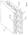
- FIGS. 4a to 4c show a further embodiment of an end wall module according to the invention.
- a first wall 3a "'with a first rib structure 8a"' with webs 4a "' is shown
- the second wall 3b"' has rib structures 4b "'with webs 8b"' between which are arranged at right angles stiffening webs 7, which, however never touch the opposite stiffening webs 7.
- the webs 4b '' have kinks in the course direction 18.
- FIG. 4b shows a plan view of the first wall 3b '
- FIG. 4c shows a side view of the first wall 3b' '.
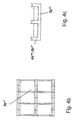
- Fig. 5 shows a plan view of a wall 3b "".
- the rib structures are formed as adjacent honeycomb 16.
- the honeycombs may also have a "chaotic" course, since in the uniform arrangement in Fig. 5 may cause acoustic problems.
- FIG. 6 shows a section through a honeycomb 16.
- recesses 17 are shown on the upper side of the honeycomb, which enable a better distribution of honeycomb to honeycomb during foaming.
- the attachment on the top is mainly for production reasons advantageous, in principle, corresponding recesses would be possible on the underside of the honeycomb webs.
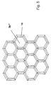
- FIG. 7 shows another embodiment of a second wall 3b '''.
- These show mutually parallel webs 4b ""'of a rib structure 8b ""'.
- These webs have a zig-zag structure in the direction 18, ie in their direction of travel.
- This zigzag gradient which runs in the direction of a plane of the wall surface, also ensures that a better "thrust” is given, also with respect to bending advantages are achieved because the effective length of the webs based on the surface of the wall 3b ""'is longer and thus a better area moment of inertia is achieved, which is particularly important in bending in the frontal crash case.
- the end wall module according to the invention shown here offers an integrated very good sound insulation.
- This is not a construction of an end wall with an additional insulation arranged on it, it is particularly important that the insulation is already integrated.
- the two layers ie the first and the second wall
- Both walls in this case have a common voltage zero lying between the individual layers, resulting in an increased area moment of inertia, due to the increased spacing of the individual walls from the voltage zero line (Steiner proportion).
- the advantage of this variant lies in the possible smaller dimensioning of the end wall, wherein the total mass of the system is further reduced can be.
Landscapes
- Engineering & Computer Science (AREA)
- Mechanical Engineering (AREA)
- Chemical & Material Sciences (AREA)
- Combustion & Propulsion (AREA)
- Transportation (AREA)
- Structural Engineering (AREA)
- Architecture (AREA)
- Physics & Mathematics (AREA)
- Acoustics & Sound (AREA)
- Body Structure For Vehicles (AREA)
- Vehicle Interior And Exterior Ornaments, Soundproofing, And Insulation (AREA)
- Piezo-Electric Or Mechanical Vibrators, Or Delay Or Filter Circuits (AREA)
- Control Of Motors That Do Not Use Commutators (AREA)
Description
- Die vorliegende Erfindung betrifft ein Stirnwandmodul für ein Kraftfahrzeug nach dem Oberbegriff des Anspruches 1.
- Stirnwandmodule für Kraftfahrzeuge sind prinzipiell bekannt. Die Hauptfunktion eines solchen Stirnwandmoduls ist die Trennung des Motorraums zum Fahrzeuginnenraum bei Kraftfahrzeugen. Dieses Stirnwandmodul muss insbesondere bei modernen höherwertigen Kraftfahrzeugen besonderen Anforderungen gerecht werden. Hierzu gehört zum einen eine gute Schallabdämmung vom Motorraum zum Kraftfahrzeuginnenraum hin und außerdem eine möglichst gute Versteifung der Karosserie zur Verringerung von Torsionsschwingungen um die Fahrzeuglängsachse. Trotz dieser Anforderungen sollte das Stirnwandmodul nur ein geringes Gewicht aufweisen.
- Es ist bekannt, Stirnwandmodule bzw. Stirnwände vorzusehen, welche zumindest bereichsweise eine Sandwichstruktur haben. D.h., dass eine erste sowie davon beabstandet eine zweite Wand vorgesehen ist. Diese Wände sind über eine relativ "harte" Schaumschicht verbunden.
- Ein derartiges Stirnwandmodul ist beispielsweise aus der DE 19946655 A bekannt geworden, die auch den Oberbegriff des Anspruchs 1 definiert.
- Diese Konstruktion gewährleistet zwar eine relativ hohe Steifigkeit der Gesamtkonstruktion, allerdings sind die Eigenschaften in Bezug auf die Schallübertragung ungenügend. Der relativ "harte" Schaum bewirkt eine direkte Körperschallübertragung von Vibrationen aus dem Motorraum in den Fahrzeuginnenraum. Durch Vorsehung eines relativ "weichen" Schaums wird die Stabilität der Konstruktion jedoch insbesondere im Kollisionsfall derart verringert, dass ein ungenügender Fahrzeuginsassenschutz gegeben ist.
- Der vorliegenden Erfindung liegt daher die Aufgabe zugrunde, ein Stirnwandmodul für Kraftfahrzeuge bereitzustellen, welches einerseits leichtgewichtig ist und andererseits sowohl sehr gute Schalldämmungseigenschaften als auch, insbesondere im Crashfall, eine hohe Sicherheit bietet.
- Diese Aufgabe wird durch ein Stirnwandmodul nach einem der unabhängigen Ansprüche gelöst.
- Dadurch, dass ein gattungsgemäßes Stirnwandmodul an der ersten Wand eine erste Rippenstruktur und an der zweiten Wand eine zweite Rippenstruktur aufweist, wobei die Rippenstrukturen so geformt sind, dass in einem unverformten Einbauzustand des Stirnwandmoduls die erste und zweite Rippenstruktur voneinander beabstandet sind (d.h. nicht direkt im Eingriff sind) und in zumindest einem verformten Zustand des Stirnwandmoduls (z.B. im Falle eines Frontalcrashs bei Durchbiegung des Stirnwandmoduls) erste und zweite Rippenstrukturen formschlüssig miteinander in Eingriff sind, wird diese Aufgabe gelöst.
- Eine Körperschallübertragung über die Rippenstrukturen wird aufgrund ihrer Beabstandung somit verhindert, die Luftschallübertragung wird durch den zwischen den beiden Wänden bestehenden Hohlraum unterbrochen. Somit wird gewährleistet, dass aufgrund der Doppelwandigkeit zum einen eine gute Schalldämpfung und Schalldämmung bewirkt wird (bei ausreichender Torsionsfestigkeit) und darüber hinaus im Crashfall aufgrund des in Eingrifftretens der Rippenstrukturen die Flächenträgheitsmomente, insbesondere bei Biegung stark ansteigen, so dass ein Eindringen von Komponenten aus dem Motorraum in den Fahrzeuginnenraum verhindert werden kann.
- Im Falle einer Krafteinleitung kommt es also zur Durchbiegung der kraftzugewandten Deckschicht bis die Verrippungen beider Deckschichten (Wände) sich berühren. Dabei werden die Rippenstrukturen durch eine entsprechende Konturierung geführt, so dass sie nicht aneinander vorbeigleiten können. Nachdem die Rippen beider Deckschichten "auf Block" gegangen, sind beide Deckschichten als ein Bauteil zu betrachten, welches durch den Steineanteil eine deutlich höhere Biegesteifigkeit besitzt. Im normalen Einsatzfall haben beide Deckschichten untereinander keinen Kontakt, so dass es nicht zu einem Körperschallübertrag kommen kann. Als Vorteile der Erfindung sind somit Verbesserung der akustischen Eigenschaften, mögliche Materialeinsparung, Verbindung der Vorteile einer Schallisolierung mit denen eines Sandwichsystems, zusätzliche Energieabsorption zwischen eventuell im Zwischenraum bestehendem Schaum und den innen liegenden Rippenstrukturen etc. zu nennen.
- Weiterbildungen der Erfindung werden in den abhängigen Ansprüchen beschrieben.
- Eine Weiterbildung des Stirnwandmoduls sieht vor, dass an der ersten und/oder zweiten Wand auf der von der jeweils anderen Wand abgewandten Seite Komponenten wie Klimaanlagenteile oder dergleichen angeordnet sind. Hierdurch wird Masse an der Wand angebracht, damit die Wand gemeinsam mit diesen Komponenten quasi als "Feder-Masse-System" schwingt. Aufgrund der Rippenstrukturen, welche auch die Biegesteifigkeit der entsprechenden Wand erhöhen, wird die Wand versteift, so dass es nicht zu Biegeschwingungen innerhalb der Wand selbst kommen kann. Durch die Rippenstrukturen wird also gesichert, dass die gesamte Wand (bzw. ein gewünschter Teil) als "Einheit" schwingt, hierdurch wird die Masse der angekoppelten Komponente quasi "akustisch wirksam". Es ist hierbei besonders vorteilhaft, wenn das Gewicht der angehängten Komponenten größer als 2 kg/m2 Flächengewicht beträgt. Insbesondere durch die Versteifung in Verbindung mit der Ankopplung von Gewicht kann somit die gesamte Stirnwand als Feder-Masse-System angesehen werden und ist daher weniger anfällig für aus dem Motorraum stammende Vibrationen. Durch diese Maßnahme kann insbesondere eine sogenannte "Schwermatte" (mit 3,5 bis 6 kg/m2) eingespart werden, deren einzige Aufgabe die Erhöhung der akustisch wirksamen Masse ist, welche auf der anderen Seite jedoch aufgrund ihres ansonsten unnötigen Ballastes die Verbrauchswerte der Kraftfahrzeuge erhöht.
- Eine weitere vorteilhafte Weiterbildung sieht vor, dass im Zwischenraum zwischen erster und zweiter Wand Schaum (etwa Polyurethanschaum) angeordnet ist oder ein Hohlraum besteht. Im Falle eines Hohlraums, welcher z.B. im Wesentlichen luftdicht abzuschließen ist, wird die Luftschallübertragung auf ein Minimum reduziert. Aufgrund der fehlenden Verbindung der Rippenstrukturen zueinander ist außerdem die Körperschallübertragung reduziert. Der Schaum kann entweder den gesamten Zwischenraum ausfüllen (in diesem Falle sollte ein relativ "weicher Schaum" gewählt werden, um die Körperschallübertragung gering zu halten.
- Eine weitere vorteilhafte Weiterbildung sieht vor, dass die erste und/oder zweite Rippenstruktur Stege aufweist. Diese Stege können entweder "stabförmig" sein und zu der jeweils anderen Wand hin gerade gerichtet sein. Besser ist es jedoch, wenn diese Stege (z.B. mit gleichbleibendem Querschnitt) z.B. senkrecht herausstehend über eine größere Länge auf der ersten bzw. zweiten Wand stehen. Hierdurch wird gewährleistet, dass diese Rippenstrukturen zum einen eine Erhöhung der Steifigkeit der Wände bewirken. Außerdem schwingen die Stege hierbei nicht bezüglich der Wand, so dass keine zusätzlichen Schallquellen entstehen.
- Es ist hierbei möglich, dass z.B. die erste Rippenstruktur stets Stege gleicher Länge (d.h. in der Raumrichtung zu der zweiten Wand hin) aufweist. In diesem Falle laufen die Stege quasi "bis zur Mittellinie", hierdurch sind die Steifigkeiten beider Wände relativ gleich hoch zu gestalten.
- Es ist jedoch auch möglich, dass die erste Rippenstruktur Stege mit jeweils unterschiedlicher Länge in Richtung zur zweiten Wand hin aufweist. Hierdurch wird erreicht, dass z.B. bei der Produktion des Stirnwandmoduls das Einlegen einer "Schaumkurve" erleichtert wird. Außerdem kann z.B. durch diese "Verzahnung", welche komplementär auf der gegenüberliegenden Wand gegeben ist, bei Schubbeanspruchung des Stirnwandmoduls eine noch höhere Stabilität gewährleistet.
- Eine besonders vorteilhafte Weiterbildung sieht vor, dass der Abstand zwischen den Stegen einer Rippenstruktur zwischen 2 mm bis 200mm, vorzugsweise 4 mm bis 25 mm beträgt.
- Eine weitere besonders vorteilhafte Weiterbildung sieht vor, dass die Stege auf ihrer zu der jeweils gegenüberliegenden Wand weisenden Fläche (also ihrer Stirnfläche) in ihrer Verlaufsrichtung Krümmungen und/oder Knicke aufweisen. Hierdurch wird quasi ein "mehrdimensionales" Design erreicht. Es können einerseits in einer Raumrichtung parallel zur Wandflächenebene, auf welcher der Steg steht, Knicke bzw. Krümmungen angeordnet sein (z.B. ein Zick-Zack-Verlauf der Stege). Andererseits kann auch senkrecht zur Wandflächenebene eine Knickung bzw. Krümmung bestehen (dies bewirkt praktisch, dass der Steg bezüglich der Wand, auf welcher er angeordnet ist, in seinem Verlauf unterschiedliche Höhen aufweist). Mit Krümmungen bzw. Knicken wird stets erreicht, dass eine noch bessere "Verzahnung" der gegenüberliegenden Rippenstrukturen erreicht wird. Dabei ist es selbstverständlich, dass die Knicke bzw. Krümmung so komplementär sind, dass ein Formschluss der gegenüberliegenden Rippenstrukturen entsprechende Verformung gegeben ist.
- Es ist stets vorteilhaft, dass die Stege der ersten Rippenstruktur an ihren zu der zweiten Rippenstruktur hinweisenden Enden konkave oder konvexe Gestalt aufweisen, die hierzu komplementären Stege weisen eine entsprechend komplementäre Struktur auf. Die Enden der Stege können im Querschnitt entweder spitz zulaufend (z.B. im Dreiecksquerschnitt) oder mit einem sphärischen Querschnitt gestaltet sein.
- Eine andere Möglichkeit sieht vor, dass die erste Rippenstruktur Stege aufweist und die zweite Rippenstruktur Hohlräume zur Aufnahme dieser Stege. Die Rippenstrukturen werden hierbei quasi als "Trigger" konstruiert. Eine erste Rippenstruktur drückt in die gegenüberliegende Rippenstruktur, welche z.B. mittig einen Hohlraum bis zu der jeweiligen Wand hin aufweist. Bei einem Crash kann eine mit Stegen ausgestattete Rippenstruktur in den Hohlraum der gegenüberliegenden Rippenstruktur eintauchen und hierbei Energie aufnehmen. Besonders vorteilhaft ist, wenn die Stege gegenüber den korrespondierenden Hohlräumen ein leichtes seitliches Übermaß aufweisen, so dass Reibarbeit bei Einführen in die Hohlräume verrichtet wird, welche Crashenergie aufzehrt. Hierbei können auch die Innenseiten der Hohlräume bzw. die Außenseiten der Stege mit einer rauhen Oberfläche ausgestattet sein (Mikroverrastung) oder mit korrespondierenden größeren Rastelementen. Hierdurch wird erreicht, dass nach völligem Eindringen der Stege in die Hohlräume ein besonders fester Verbund beider Wände entsteht, welcher unlösbar ist und dessen Flächenträgheitsmoment aufgrund der Unverschiebbarkeit der Wände zueinander besonders hoch ist.
- Eine weitere vorteilhafte Weiterbildung sieht vor, dass die geringste Spaltbreite zwischen erster und zweiter Rippenstruktur zwischen 0,5 und 5 mm, bevorzugt 1 mm bis 2 mm beträgt. Hierdurch wird gewährleistet, dass der Körperschall zwischen erster und zweiter Wand auch bei leichten Vibrationen der ersten bzw. zweiten Wand nicht übertragen wird.
- Eine weitere vorteilhafte Weiterbildung sieht vor, dass die Fläche der zweiten Wand auf der der ersten Wand abgewandten Seite mindestens 10, vorzugsweise 20, besonders vorzugsweise 30 % mehr Fläche aufweist als die erste Wand auf ihrer von der zweiten Wand abgewandten Seite. Dies ist besonders vorteilhaft, wenn das Stirnwandmodul in einen Rahmen zur Einfassung des Stirnwandmoduls eingeführt wird, welcher in einer Kraftfahrzeugkarosserie vorgesehen ist. In diesem Falle ist das Stirnwandmodul zumindest aus einer Richtung (z.B. vom Fahrzeuginnenraum her) leicht in den Stirnwandrahmen einzufügen, das flächenmäßige Übermaß der zweiten Wand sorgt hierbei zum einen aufgrund der Berührfläche mit den Stirnwandrahmen für eine besonders gute Festigkeit (diese kann insbesondere dadurch erhöht werden, dass der Stirnwandrahmen mit dem Stirnwandmodul verklebt und zusätzlich verschraubt wird). Es ist hierbei besonders vorteilhaft, wenn z.B. auf der der ersten Wand abgewandten Seite der zweiten Wand im Bereich des örtlich überragenden Flächenanteils zusätzliche Versteifungsrippen gegeben sind. Hierdurch wird erreicht, dass die hohe akustisch wirksame Masse der zweiten Wand bis in den Randbereich der zweiten Wand wirksam ist.
- Eine besonders vorteilhafte Weiterbildung sieht vor, dass die erste und/oder zweite Wand und/oder die Rippenstrukturen aus Kunststoff oder Metall sind (Es sollten hierbei Materialien vorgesehen werden, die bei über 140°C dauertemperaturbeständig sind). Es ist vorteilhaft, wenn Wand und Rippenstrukturen einteilig sind, dies ermöglicht z.B. eine günstigere Stellung im Spritzgußverfahren. Es sind selbstverständlich auch zweiteilige Ausführungen möglich. Als Materialien kommen Metalle oder insbesondere Kunststoffe in Betracht. Als Kunststoffe kommen Polypropylen, Polyester (wie z.B.' PET, PBT) Polyamid oder Polyethylen in Betracht, alle mit 30 bis 50 Gew.-% Glasfaseranteil. Entsprechend können auch Kohlefasern oder Aramidfasern zugeschlagen werden. Die Wandstärke der ersten bzw. zweiten Wand beträgt bei Kunststoff vorzugsweise 1 bis 6 mm, besonders vorzugsweise 3 mm. Der E-Modul beträgt 8000 bis 12000 Mega Pascal.
- Weitere vorteilhafte Weiterbildungen der vorliegenden Erfindung werden in den übrigen abhängigen Ansprüchen behandelt.
- Die Erfindung wird nun anhand mehrerer Figuren im Detail erläutert. Es zeigen:
- Fign. 1a bis 1c
- verschiedene Ausführungsformen eines erfindungsgemäßen Stirnwandmoduls im Querschnitt im unverformten Zustand,
- Fig. 2
- ein Stirnwandmodul nach Fig. 1a im verformten Zustand,
- Fig. 3a
- eine Ansicht einer Kraftfahrzeugkarosserie mit Stirnwandrahmen vom Innenraum des Kraftfahrzeuges aus gesehen,
- Fig. 3b
- einen Schnitt gemäß A-A von Fig. 3a,
- Fig. 4a bis 4c
- eine weitere Ausführungsform eines erfindungsgemäßen Stirnwandmoduls,
- Fig. 5
- eine Draufsicht einer rippenförmigen Waben- struktur,
- Fig. 6
- einen Schnitt durch eine Wabe gemäß Fig. 5, sowie
- Fig. 7
- eine weitere Ausführungsform einer zweiten Wand eines Stirnwandmoduls.
- Fig. 1a zeigt einen Ausschnitt eines Querschnittes durch ein Stirnwandmodul 1 für ein Kraftfahrzeug. Das Stirnwandmodul weist eine erste Wand 3a sowie davon beabstandet eine zweite Wand 3b auf. Die erste Wand 3a weist eine Rippenstruktur 4a auf. Die zweite Wand 3b weist eine zweite Rippenstruktur 4b auf.
- Die erste Rippenstruktur 4a weist Stege 8a auf, welche sich in Richtung senkrecht zur Zeichenebene in der Länge erstrecken. Die erste Rippenstruktur weist außerdem hierzu kreuzende Versteifungsstege 7 auf der ersten Wand 3a auf. Die Stege 8a haben an ihrem zu der zweiten Wand 3b hinweisenden Ende dreieckförmige Spitzen. Die zweite Wand 3b weist ebenfalls Stege 8b auf, welche zur zweiten Rippenstruktur 4b gehören sowie ebenfalls hierzu kreuzende Versteifungsstege 7. Diese Stege 8b weisen an ihrem zu der ersten Wand 3a hinweisenden Ende eine zu den Spitzen der Stege 8a komplementäre, ebenfalls im Querschnitt dreieckförmige Form auf, und zwar in Form einer Ausbuchtung. Zwischen den Spitzen der Stege 8a sowie den Aufnahmen der Stege 8b ist ein Spalt vorgesehen, welcher mindestens zwischen 0,5 mm und 5 mm groß ist.
- Das Stirnwandmodul in Fig. 1a zeigt außerdem Schaumbereiche 6. Hierbei handelt es sich um einen Polyurethanschaum. Zur noch besseren Schallisolierung kann der Bereich zwischen erster und zweiter Wand auch bereichsweise evakuiert sein.
- Somit handelt es sich bei dem Stirnwandmodul nach Fig. 1a um ein Stirnwandmodul mit erster und zweiter Wand und jeweiligen Rippenstrukturen, wobei die Rippenstrukturen so geformt sind, dass in dem in Fig. 1a gezeigten unverformten Einbauzustand des Stirnwandmoduls die erste und zweite Rippenstruktur voneinander beabstandet sind. Es wird später darauf eingegangen (siehe Fig. 2), wie bei Biegebelastung des Stirnwandmoduls die gegenüberliegenden Stege 8a bzw. 8b der Rippenstrukturen miteinander in Eingriff geraten.
- Der Abstand zwischen den einzelnen Stegen 8a beträgt wie in Fig. 1a mit x1 bezeichnet zwischen 3 und 6 mm. Die zu wählende Stegbreite t hängt von dem Abstand x2 und dem Winkel α der Stegspitzen ab. Bei α = 90° sowie x2 = 1 mm ist die minimale Stegbreite t vorzugsweise größer als 3 mm (alle in Fig. 1a gezeigten Stegpaare haben identische Abmessungen).
- Fig. 1b zeigt eine alternative Ausführungsform eines Stirnwandmoduls 1'. Hierbei ist ebenfalls eine erste Wand 3a' und eine zweite Wand 3b' gezeigt. Im Unterschied zu dem Stirnwandmodul nach Fig. 1a haben die Stege 8a' der ersten Rippenstruktur 4a' in Richtung senkrecht zur Flächenebene der ersten Wand 3a' nicht dieselbe Länge, sondern die Stege weisen, hier im alternierenden Wechsel, unterschiedliche Steglängen auf. Entsprechendes gilt für die Längen der Stege 8b' der zweiten Wand 4b'. Dies ist nötig, damit zwischen den jeweiligen Stegspitzen etwa gleiche Spaltbreiten bestehen. Somit weist in Fig. 1a die erste sowie zweite Rippenstruktur jeweils Stege mit in Richtung der jeweils anderen Wand gleicher Länge auf. In Fig. 1b weisen die erste und zweite Rippenstruktur jeweils Stege mit in Richtung der jeweils anderen Wand unterschiedlicher Länge auf.
- Eine eventuell vorhandene Schäumung im Zwischenraum zwischen der ersten Wand 3a' und zweiten Wand 3b' ist in Fig. 1b nicht dargestellt.
- Fig. 1c zeigt eine weitere Ausführungsform 1" eines erfindungsgemäßen Stirnwandmoduls. Dieses weist wiederum eine erste Wand 3a" sowie eine zweite Wand 3b" auf. Die erste Wand 3a" weist eine erste Rippenstruktur 4a" mit Stegen 8a" auf. Die zweite Wand 3b" weist eine Rippenstruktur 4b" auf. Die zweite Rippenstruktur 4b" weist Hohlräume 8b" zur Aufnahme der Stege 8a" auf. Die Stege 8a" bzw. die den Stegen zugewandten Enden der Berandung der Hohlräume 8b" können Einlaufschrägen aufweisen. Die Hohlräume 8b" weisen zueinander einen geringeren Abstand auf als die Breite der Stege 8a", so dass im Fall eines Eindringens der Stege 8a" in die Hohlräume 8b" aufgrund des Übermaßes Verformungsarbeit verrichtet wird, welche Crashenergie auffängt. Hierbei können die korrespondierenden Flächen jeweils mit einer rauhen Oberfläche zur Gewährleistung von Mikroverrastung oder auch mit korrespondierenden Rastnasen ausgestattet werden, welche ein Trennen von erster Wand 3a" und 3b" verhindern.
- Fig. 2 zeigt das Stirnwandmodul nach Fig. 1a in einem verformten Zustand. Durch Aufbringung einer Biegekraft F kommt es zu einer Durchbiegung des Stirnwandmoduls 1, wie es im Falle einer Frontalkollision des Kraftfahrzeuges der Fall wäre. Hierdurch geraten die Rippenstrukturen 4a sowie 4b mit ihren Stegen 8a bzw. 8b miteinander in Eingriff. Durch diesen Eingriff wird die Biegesteifigkeit des Stirnwandmoduls drastisch erhöht, wodurch ein Eindringen von Motorraumkomponenten im Fahrzeuginnenraum verhindert werden kann.
- Sämtliche in den Figuren dargestellten Stirnwandmodule weisen erste bzw. zweite Wände aus Kunststoff auf. Wand und Rippenstruktur bilden jeweils ein einziges Teil, wie aus der Schraffur ersichtlich ist.
- Fig. 3a zeigt einen Teil des Kraftfahrzeugs 2, nämlich die Rohkarosserie eines Kraftfahrzeugs 2 vom Innenraum aus gesehen. Hier ist ein Stirnwandrahmen 10 erkennbar, welcher in seinem Inneren eine Stirnwandöffnung aufweist, in welcher das Stirnwandmodul 1 montiert ist.
- In Fig. 3b ist ein Schnitt A-A gezeigt. Hierin ist das Stirnwandmodul mit seiner ersten Wand 3a und seiner zweiten Wand 3b zu sehen. Rippenstrukturen 4a bzw. 4b sowie andere Bestandteile des Sandwichaufbaus sind bereits oben erläutert worden, so dass zur Vermeidung von Wiederholungen hierauf verwiesen wird. Das Stirnwandmodul ist über Schraubverbindungen 14 mit einer Blechstruktur 13 des Rahmens 10 verbunden. Neben diesen Verschraubungen ist das Stirnwandmodul 1 auch noch über eine nicht dargestellte Klebeschicht mit der Blechstruktur 13 großflächig verbunden. Die zweite Wand 3b überragt an den seitlichen Außenrändern die erste Wand 3a. Aus Fign. 3a und 3b ist ersichtlich, dass die Außenkante der ersten Wand mit 15 bezeichnet ist (durchgehende Linie in Fig. 3a) und die Außenkante der zweiten Wand mit 12 (schraffierte Linie in Fig. 3a). Die zweite Wand überragt die erste Wand flächenmäßig insgesamt um 10 %.
- Die zweite Wand weist auf ihrer von der ersten Wand 3a abgewandten Seite eine Außenrippenstruktur 9 auf, welche durchgehend vom gemeinsamen Überlappungsbereich von Wand 3a und 3b (d.h. innerhalb des Bereiches 12 in Fig. 3a) bis in den Randbereich des überragenden Bereiches der Wand 3b (also innerhalb der schraffierten Linie 15 in Fig. 3a) reicht. Hierdurch wird eine Versteifung der zweiten Wand insbesondere in diesem überragenden Bereich erreicht, wodurch erreicht wird, dass die zweite Wand z.B. insgesamt (also auf ihrer Gesamtfläche) als einheitlich schwingendes System modelliert werden kann. Auf der der Wand 3a abgewandten Außenseite der zweiten Wand 3b sind außerdem Komponenten 5 wie z.B. Teile einer Klimaanlage fest angeordnet. Hierdurch wird erreicht, dass die Masse dieser Klimaanlagenteile, welche ohnehin in dem Fahrzeug untergebracht werden müssen, außerdem noch die Zusatzaufgabe erfüllen, die zweite Wand 3b (Analoges ist auch zusätzlich für die erste Wand 3a möglich) zu beschweren. Aufgrund der Rippenstrukturen 4b bzw. 9 wird somit erreicht, dass die gesamte zweite Wand quasi als "Einmassenschwinger" zu betrachten ist. Es ist somit nicht mehr nötig, wie bei Kraftfahrzeugen nach dem Stand der Technik, den gesamten innerhalb der strichlierten Linie 12 befindlichen Bereich z.B. mit einer Schwermatte zu belegen und hiermit unnötigen Ballast zu verursachen.
- In Fig. 4a bis 4c ist eine weitere Ausführungsform eines erfindungsgemäßen Stirnwandmoduls gezeigt. Hierbei ist eine erste Wand 3a"' mit einer ersten Rippenstruktur 8a"' mit Stegen 4a"' gezeigt. Die zweite Wand 3b"' weist Rippenstrukturen 4b"' auf mit Stegen 8b"', zwischen denen rechtwinklig Versteifungsstege 7 angeordnet sind, welche jedoch die gegenüberliegenden Versteifungsstege 7 nie berühren. Die Stege 4b"' weisen in Verlaufsrichtung 18 Knicke auf. Dies kommt dadurch zustande, dass die Stege in Verlaufsrichtung unterschiedliche Höhen bezüglich der Wandflächenebene der Wand 3b"' aufweisen. Dieser Höhenverlauf führt dazu, dass eine noch bessere Verzahnung im Kollisionsfall gegeben ist (noch bessere Verhinderung des Schubs zwischen erster und zweiter Wand, außerdem ist diese Geometrie beim Ausschäumen vorteilhaft, da durch die geringeren Steghöhen das Schaumausgangsmaterial über die durch die Versteifungsstege 7 sowie die Stege 4b"' begrenzten Kammern leichter von Kammer zu Kammer wandern kann.
- Fig. 4b zeigt eine Draufsicht auf die erste Wand 3b"' sowie Fig. 4c zeigt eine Seitenansicht der ersten Wand 3b"'.
- Fig. 5 zeigt eine Draufsicht auf eine Wand 3b"".
Hierbei sind die Rippenstrukturen als aneinander liegende Waben 16 ausgebildet. Die Waben können auch einen "chaotischen" Verlauf haben, da bei der gleichmäßigen Anordnung in Fig. 5 unter Umständen akustische Probleme entstehen. - Fig. 6 zeigt einen Schnitt durch eine Wabe 16. Hierbei sind Ausnehmungen 17 auf der Oberseite der Wabe gezeigt, welche ermöglichen, dass beim Ausschäumen eine bessere Verteilung von Wabe zu Wabe gegeben ist. Die Anbringung auf der Oberseite ist vor allem aus produktionstechnischen Gründen vorteilhaft, prinzipiell wären auch entsprechende Ausnehmungen auf der Unterseite der Wabenstege möglich.
- Schließlich zeigt Fig. 7 eine weitere Ausführungsform einer zweiten Wand 3b""'. Diese zeigen zueinander parallele Stege 4b""' einer Rippenstruktur 8b""'. Diese Stege weisen in Richtung 18, also in ihrer Verlaufsrichtung, eine Zick-Zack-Struktur auf. Dieser ZickZack-Verlauf, welcher in Richtung einer Wandflächenebene verläuft, sorgt ebenfalls dafür, dass eine bessere "Schubverzahnung" gegeben ist, auch bezüglich Biegung werden Vorteile erreicht, da die effektive Länge der Stege bezogen auf die Fläche der Wand 3b""' länger ist und somit ein besseres Flächenträgheitsmoment erreicht wird, was insbesondere bei Biegung im Frontalchrashfall wichtig ist.
- Abschließend wird betont, dass insbesondere die in Fign. 4a bis 4c sowie in Fig. 7 gezeigten Knick- bzw. Krümmungsformen der Stege auch auf sämtliche anderen Ausführungsformen, insbesondere auf die Ausführungsformen von Fig. 1a bis 1c, anwendbar sind.
- Es ist wesentlich, dass das hier gezeigte erfindungsgemäße Stirnwandmodul eine integrierte sehr gute Schallisolation bietet. Es handelt sich hierbei nicht um einen Aufbau einer Stirnwand mit einer darauf angeordneten zusätzlichen Isolation, es ist besonders wichtig, dass die Isolation bereits integriert ist. Dadurch können, anders als bei zusätzlich aufgesetzten Wabenstrukturen auf der Außenseite der Stirnwand auch hohe Schubkräfte aufgenommen werden und es ergibt kein sehr hohes Gesamtflächenträgheitsmoment. Nach der vorliegenden Erfindung kommt es im Falle einer Belastung bzw. eines Crashs zu einer Verhakung der beiden Schichten (d.h. der ersten und der zweiten Wand). Beide Wände haben in diesem Fall eine gemeinsame zwischen den einzelnen Schichten liegende Spannungsnulllinie, wobei sich ein erhöhtes Flächefiträgheitsmoment, bedingt durch die erhöhte Beabstandung der Einzelwände von der Spannungsnulllinie (Steiner-Anteil) ergibt. Der Vorteil dieser Variante liegt in der möglichen geringeren Dimensionierung der Stirnwand, wobei die Gesamtmasse des Systems weiter reduziert werden kann.
Claims (18)
- Stirnwandmodul (1) für ein Kraftfahrzeug (2), wobei das Stirnwandmodul eine erste (3a) sowie davon beabstandet eine zweite (3b) Wand aufweist,
dadurch gekennzeichnet,
daß die erste Wand eine erste Rippenstruktur (4a) und die zweite Wand eine zweite Rippenstruktur (4b) aufweist, wobei die Rippenstrukturen so geformt sind, daß in einem unverformten Einbauzustand des Stirnwandmoduls die erste und zweite Rippenstruktur voneinander beabstandet sind und in zumindest einem verformten Zustand des Stirnwandmoduls erste und zweite Rippenstrukturen formschlüssig miteinander in Eingriff sind. - Stirnwandmodul nach Anspruch 1, dadurch gekennzeichnet, daß an der ersten (3a) und/oder zweiten Wand (3b) auf der von der jeweils anderen Wand abgewandten Seite Komponenten wie Klimaanlagenteile (5) oder dergleichen angeordnet sind.
- Stirnwandmodul nach einem der vorhergehenden Ansprüche, dadurch gekennzeichnet, daß zwischen erster (3a) und zweiter (3b) Wand Schaum (7) angeordnet ist und/oder ein Hohlraum besteht.
- Stirnwandmodul nach einem der vorhergehenden Ansprüche, dadurch gekennzeichnet, daß die erste (4a) und/oder zweite (4b) Rippenstruktur Stege (8a, 8b) aufweist.
- Stirnwandmodul nach Anspruch 4, dadurch gekennzeichnet, daß die erste (4a) und/oder zweite (4b) Rippenstruktur jeweils Stege (8a, 8b) mit in Richtung der jeweils anderen Wand gleicher Länge aufweist.
- Stirnwandmodul nach Anspruch 4, dadurch gekennzeichnet, daß die erste (4a') und zweite (4b') Rippenstruktur jeweils Stege (8a', 8b') mit in Richtung der jeweils anderen Wand unterschiedlicher Länge aufweisen.
- Stirnwandmodul nach einem der Ansprüche 4 bis 6, dadurch gekennzeichnet, daß zwischen den Stegen (8a, 8b) einer Rippenstruktur (4a, 4b) der Abstand zwischen 2 mm und 200 mm, bevorzugt zwischen 4 mm und 25 mm beträgt.
- Stirnwandmodul nach einem der Ansprüche 4 bis 7, dadurch gekennzeichnet, daß die Stege (8a, 8b) der ersten Rippenstruktur (4a) an ihren zu der zweiten Rippenstruktur (4b) hinweisenden Enden konvexe oder konkave Gestalt aufweisen.
- Stirnwandmodul nach Anspruch 4, dadurch gekennzeichnet, daß die erste Rippenstruktur (4a") Stege und die zweite Rippenstruktur (4b") Hohlräume (8b") zur Aufnahme dieser Stege aufweist.
- Stirnwandmodul nach einem der vorhergehenden Ansprüche, dadurch gekennzeichnet, daß die geringste Spaltbreite zwischen erster (4a) und zweiter (4b) Rippenstruktur zwischen 0,5 mm und 5,0 mm, bevorzugt zwischen 1 mm und 2 mm beträgt.
- Stirnwandmodul nach einem der vorhergehenden Ansprüche, dadurch gekennzeichnet, daß die zweite Wand (3b) des Stirnwandmoduls (1) die erste Wand (3a) zumindest bereichsweise seitlich überragt.
- Stirnwandmodul nach Anspruch 11, dadurch gekennzeichnet, daß die Fläche der zweiten Wand (3b) auf der der ersten Wand (3a) abgewandten Seite mindestens 10, vorzugsweise 20, besonders vorzugsweise 30 % mehr Fläche aufweist als die erste Wand auf ihrer von der zweiten Wand abgewandten Seite.
- Stirnwandmodul nach einem der Ansprüche 11 oder 12, dadurch gekennzeichnet, daß die zweite Wand (3b) in den seitlich überragenden Bereichen auf ihrer der ersten Wand abgewandten Seite eine Außenrippenstruktur aufweist.
- Stirnwandmodul nach einem der vorhergehenden Ansprüche, dadurch gekennzeichnet, daß die erste (3a) und/oder zweite (3b) Wand und/oder die Rippenstrukturen (4a, 4b) aus Kunststoff oder Metall sind.
- Stirnwandmodul nach einem der Ansprüche 4 bis 14, dadurch gekennzeichnet, dass die Stege (4a"', 4b"') auf ihrer zu der jeweils gegenüberliegenden Wand weisenden Stirnfläche in ihrer Verlaufsrichtung Krümmungen und/oder Knicke aufweisen.
- Kraftfahrzeug, enthaltend ein Stirnwandmodul (1) nach einem der vorhergehenden Ansprüche.
- Kraftfahrzeug nach Anspruch 16, dadurch gekennzeichnet, daß dieses einen Rahmen (10) zur Einfassung des Stirnwandmoduls (1) einhält.
- Kraftfahrzeug nach Anspruch 17, dadurch gekennzeichnet, daß das Stirnwandmodul mit dem Rahmen (10) zur Einfassung verschraubt und/oder verklebt ist.
Priority Applications (1)
| Application Number | Priority Date | Filing Date | Title |
|---|---|---|---|
| SI200330415T SI1545962T1 (sl) | 2002-10-02 | 2003-10-02 | Celnostenski modul |
Applications Claiming Priority (3)
| Application Number | Priority Date | Filing Date | Title |
|---|---|---|---|
| DE10246994A DE10246994B3 (de) | 2002-10-02 | 2002-10-02 | Stirnwandmodul |
| DE10246994 | 2002-10-02 | ||
| PCT/EP2003/010957 WO2004056639A1 (de) | 2002-10-02 | 2003-10-02 | Stirnwandmodul |
Publications (2)
| Publication Number | Publication Date |
|---|---|
| EP1545962A1 EP1545962A1 (de) | 2005-06-29 |
| EP1545962B1 true EP1545962B1 (de) | 2006-05-24 |
Family
ID=32102733
Family Applications (1)
| Application Number | Title | Priority Date | Filing Date |
|---|---|---|---|
| EP03813027A Expired - Lifetime EP1545962B1 (de) | 2002-10-02 | 2003-10-02 | Stirnwandmodul |
Country Status (10)
| Country | Link |
|---|---|
| US (1) | US7497506B2 (de) |
| EP (1) | EP1545962B1 (de) |
| JP (1) | JP3949138B2 (de) |
| CN (1) | CN100393568C (de) |
| AT (1) | ATE327137T1 (de) |
| AU (1) | AU2003303108A1 (de) |
| BR (1) | BR0314974A (de) |
| DE (2) | DE10246994B3 (de) |
| ES (1) | ES2264039T3 (de) |
| WO (1) | WO2004056639A1 (de) |
Cited By (1)
| Publication number | Priority date | Publication date | Assignee | Title |
|---|---|---|---|---|
| DE102018211876A1 (de) * | 2018-07-17 | 2020-01-23 | Bayerische Motoren Werke Aktiengesellschaft | Fahrzeug-Exterieur-Komponente |
Families Citing this family (12)
| Publication number | Priority date | Publication date | Assignee | Title |
|---|---|---|---|---|
| FR2870818B1 (fr) * | 2004-05-27 | 2007-09-28 | Renault Sas | Ensemble de cockpit comprenant une structure resistante assemblee par collage |
| KR100662101B1 (ko) * | 2005-01-06 | 2006-12-27 | 주식회사 엘지화학 | 플라스틱제 판넬 |
| DE102005013635B4 (de) * | 2005-03-24 | 2020-11-26 | Volkswagen Ag | Verstärkungsrippen für Träger, insbesondere für Frontendmontageträger von Kraftfahrzeugen, sowie Spritzgießwerkzeug zur Herstellung der Verstärkungsrippen |
| US20080281734A1 (en) * | 2005-07-11 | 2008-11-13 | Appone Services, Inc. | System and method for integrated credit application and tax refund estimation |
| KR100906005B1 (ko) * | 2008-06-26 | 2009-07-06 | 엔브이에이치코리아(주) | 충격흡수부재 |
| DE102011081710B4 (de) | 2011-08-29 | 2022-11-17 | Robert Bosch Gmbh | Schutzvorrichtung zum Schutz einer Traktionsbatterie von Hybrid- oder Elektrofahrzeugen |
| DE102013216191B4 (de) * | 2013-08-14 | 2021-10-21 | Faurecia Innenraum Systeme Gmbh | Verfahren zur Herstellung eines Trägerelements und Trägerelement für ein Transportmittel |
| DE102013113210A1 (de) * | 2013-11-29 | 2015-06-18 | Connova Ag | Wärmeschutzvorrichtung für ein Kraftfahrzeug |
| DE102013113230A1 (de) * | 2013-11-29 | 2015-06-03 | Thyssenkrupp Steel Europe Ag | Verfahren zur Herstellung eines Außenverkleidungsteils für ein bewegbares Karosserieteil sowie ein entsprechendes Außenverkleidungsteil |
| JP6206303B2 (ja) * | 2014-04-07 | 2017-10-04 | マツダ株式会社 | 車両用フレーム構造 |
| EP3431345B1 (de) * | 2017-07-20 | 2020-04-01 | Faurecia Interior Systems India Pvt. Ltd. | Aufprallenergieabsorber für ein fahrzeug |
| JP7676914B2 (ja) * | 2021-04-28 | 2025-05-15 | マツダ株式会社 | 車両のパネル構造 |
Family Cites Families (18)
| Publication number | Priority date | Publication date | Assignee | Title |
|---|---|---|---|---|
| US3933387A (en) * | 1975-03-10 | 1976-01-20 | General Motors Corporation | Thermoformed plastic energy absorber for vehicles |
| US4555134A (en) * | 1983-07-20 | 1985-11-26 | Leo Gruna | Crush resistant motor vehicle body |
| DE69613760T2 (de) * | 1995-05-24 | 2002-05-29 | Sai Automotive Sommer Industrie, Nanterre | Schalldämpfendes Produkt mit integriertem Energiedämpfer und Verfahren zu dessen Herstellung |
| JP3532678B2 (ja) * | 1995-10-03 | 2004-05-31 | 本田技研工業株式会社 | エンジンルームと車室間の隔壁 |
| WO1998018656A1 (de) * | 1996-10-29 | 1998-05-07 | Rieter Automotive (International) Ag | Ultraleichter multifunktionaler, schallisolierender bausatz |
| JP3867332B2 (ja) * | 1997-01-29 | 2007-01-10 | トヨタ車体株式会社 | 車両における衝撃吸収樹脂リブ構造 |
| US5934729A (en) * | 1997-03-10 | 1999-08-10 | Ford Global Technologies, Inc. | Energy-absorbing fastener system |
| US6752450B2 (en) * | 1998-02-04 | 2004-06-22 | Oakwood Energy Management, Inc. | Formed energy absorber |
| DE19946655A1 (de) * | 1999-09-29 | 2001-04-12 | Cww Gerko Akustik Gmbh & Co Kg | Stirnwandisolation |
| JP3330921B2 (ja) * | 2000-03-13 | 2002-10-07 | 菊池プレス工業株式会社 | テーラードブランク製物品及びその製造方法 |
| US7052077B1 (en) * | 2000-06-13 | 2006-05-30 | Meritor Light Vehicle Systems, Inc. | Crumple zone for body panels |
| DE10143564A1 (de) * | 2001-09-05 | 2003-03-20 | Basf Ag | Hohlprofilverbundbauteile |
| DE10145641A1 (de) | 2001-09-15 | 2003-04-10 | Krauss Maffei Wegmann Gmbh & C | Verfahren zur Erfassung einer Luftlage in einem Kampffahrzeug sowie Vorrichtung zur Durchführung des Verfahrens |
| DE10154593A1 (de) * | 2001-11-07 | 2003-05-15 | Arvinmeritor Gmbh | Deformationselement, insbesondere für Kraftfahrzeuge |
| US7216926B2 (en) * | 2003-10-22 | 2007-05-15 | Hampel Lance T | Vehicle cab |
| US6988761B1 (en) * | 2004-02-23 | 2006-01-24 | Brian Stidham | Interlocking channeled trailer side panels with integrated sliding outer panel inserts |
| JP4531468B2 (ja) * | 2004-07-14 | 2010-08-25 | 小島プレス工業株式会社 | 車両用衝撃吸収構造体及びその取付構造 |
| US7201434B1 (en) * | 2005-11-04 | 2007-04-10 | Cadence Innovation Llc | Energy-absorbing bolster for an automotive instrument panel assembly |
-
2002
- 2002-10-02 DE DE10246994A patent/DE10246994B3/de not_active Expired - Fee Related
-
2003
- 2003-10-02 BR BR0314974-9A patent/BR0314974A/pt not_active IP Right Cessation
- 2003-10-02 DE DE50303503T patent/DE50303503D1/de not_active Expired - Lifetime
- 2003-10-02 AT AT03813027T patent/ATE327137T1/de not_active IP Right Cessation
- 2003-10-02 US US10/530,097 patent/US7497506B2/en not_active Expired - Fee Related
- 2003-10-02 WO PCT/EP2003/010957 patent/WO2004056639A1/de not_active Ceased
- 2003-10-02 CN CNB2003801008566A patent/CN100393568C/zh not_active Expired - Fee Related
- 2003-10-02 JP JP2004561135A patent/JP3949138B2/ja not_active Expired - Fee Related
- 2003-10-02 EP EP03813027A patent/EP1545962B1/de not_active Expired - Lifetime
- 2003-10-02 ES ES03813027T patent/ES2264039T3/es not_active Expired - Lifetime
- 2003-10-02 AU AU2003303108A patent/AU2003303108A1/en not_active Abandoned
Cited By (1)
| Publication number | Priority date | Publication date | Assignee | Title |
|---|---|---|---|---|
| DE102018211876A1 (de) * | 2018-07-17 | 2020-01-23 | Bayerische Motoren Werke Aktiengesellschaft | Fahrzeug-Exterieur-Komponente |
Also Published As
| Publication number | Publication date |
|---|---|
| ES2264039T3 (es) | 2006-12-16 |
| CN1703345A (zh) | 2005-11-30 |
| ATE327137T1 (de) | 2006-06-15 |
| EP1545962A1 (de) | 2005-06-29 |
| DE10246994B3 (de) | 2004-05-13 |
| AU2003303108A1 (en) | 2004-07-14 |
| WO2004056639A1 (de) | 2004-07-08 |
| CN100393568C (zh) | 2008-06-11 |
| DE50303503D1 (de) | 2006-06-29 |
| US20060162278A1 (en) | 2006-07-27 |
| JP3949138B2 (ja) | 2007-07-25 |
| JP2006502047A (ja) | 2006-01-19 |
| BR0314974A (pt) | 2005-08-02 |
| US7497506B2 (en) | 2009-03-03 |
Similar Documents
| Publication | Publication Date | Title |
|---|---|---|
| DE60109869T2 (de) | Verkleidungsteil für die Unterseite eines Motors mit verbesserter Festigkeit | |
| EP1545962B1 (de) | Stirnwandmodul | |
| DE4332166A1 (de) | Energieabsorbierende Fahrzeugtür | |
| DE102016122663A1 (de) | Aufprallabsorptionseinheit, Herstellungsverfahren davon und Elementverbindungsstruktur | |
| DE10053840A1 (de) | Stoßfängersystem für Fahrzeuge | |
| DE102006001061A1 (de) | Kraftfahrzeug mit wenigstens einem längsseitig an seiner Karosserie verlaufenden, verstärkten Türschweller | |
| EP3953602B1 (de) | Biegefederelement aus einem faserkunststoffverbundmaterial | |
| DE112015001441T5 (de) | Fahrzeugenergie-Absorptionsstruktur und Energieabsorptionselement | |
| DE10003878A1 (de) | Zusatzelement | |
| DE102019132450A1 (de) | Batteriegehäuse für ein elektromotorisch angetriebenes Fahrzeug | |
| EP2571747A1 (de) | Kraftfahrzeug mit einem seitenschweller | |
| DE60210220T2 (de) | Doppelwandige Dämpfungsstruktur | |
| DE202007016671U1 (de) | Energieabsorber zur Verwendung als Aufprallschutz in einem Kraftfahrzeug | |
| EP4055297B1 (de) | Biegefederelement aus einem faserkunststoffverbundmaterial | |
| EP1925488B1 (de) | Instrumententafel sowie Verfahren zu deren Herstellung | |
| WO2005123459A1 (de) | Bauteil zur energieaufnahme bei einem aufprall | |
| DE102013002504A1 (de) | Kraftfahrzeug-Bodenstruktur | |
| DE102013002537A1 (de) | Schweller-Bodenstruktur-Anordnung | |
| DE69714465T2 (de) | Omnibus mit sicherheitsvorrichtungen wie eine überrollvorrichtung, sowie verfahren zum zusammenbau eines omnibuses | |
| DE102021118642A1 (de) | Seitenaufprallenergieabsorptionselement für ein Kraftfahrzeug und Kraftfahrzeug | |
| EP3348457A1 (de) | Verstärkungsstrebe für ein kraftfahrzeug | |
| EP2239128A1 (de) | Fahrzeugteil mit Strukturverstärkungsteil | |
| DE10232321B4 (de) | Stoßfängerträger für ein Fahrzeug | |
| EP2335982B1 (de) | Absorberelement für ein Kraftfahrzeug | |
| EP0943531A2 (de) | Kraftfahrzeugkarosseriestruktur |
Legal Events
| Date | Code | Title | Description |
|---|---|---|---|
| PUAI | Public reference made under article 153(3) epc to a published international application that has entered the european phase |
Free format text: ORIGINAL CODE: 0009012 |
|
| 17P | Request for examination filed |
Effective date: 20050315 |
|
| AK | Designated contracting states |
Kind code of ref document: A1 Designated state(s): AT BE BG CH CY CZ DE DK EE ES FI FR GB GR HU IE IT LI LU MC NL PT RO SE SI SK TR |
|
| AX | Request for extension of the european patent |
Extension state: AL LT LV MK |
|
| GRAP | Despatch of communication of intention to grant a patent |
Free format text: ORIGINAL CODE: EPIDOSNIGR1 |
|
| DAX | Request for extension of the european patent (deleted) | ||
| GRAS | Grant fee paid |
Free format text: ORIGINAL CODE: EPIDOSNIGR3 |
|
| GRAA | (expected) grant |
Free format text: ORIGINAL CODE: 0009210 |
|
| AK | Designated contracting states |
Kind code of ref document: B1 Designated state(s): AT BE BG CH CY CZ DE DK EE ES FI FR GB GR HU IE IT LI LU MC NL PT RO SE SI SK TR |
|
| PG25 | Lapsed in a contracting state [announced via postgrant information from national office to epo] |
Ref country code: IT Free format text: LAPSE BECAUSE OF FAILURE TO SUBMIT A TRANSLATION OF THE DESCRIPTION OR TO PAY THE FEE WITHIN THE PRESCRIBED TIME-LIMIT;WARNING: LAPSES OF ITALIAN PATENTS WITH EFFECTIVE DATE BEFORE 2007 MAY HAVE OCCURRED AT ANY TIME BEFORE 2007. THE CORRECT EFFECTIVE DATE MAY BE DIFFERENT FROM THE ONE RECORDED. Effective date: 20060524 Ref country code: NL Free format text: LAPSE BECAUSE OF FAILURE TO SUBMIT A TRANSLATION OF THE DESCRIPTION OR TO PAY THE FEE WITHIN THE PRESCRIBED TIME-LIMIT Effective date: 20060524 Ref country code: GB Free format text: LAPSE BECAUSE OF FAILURE TO SUBMIT A TRANSLATION OF THE DESCRIPTION OR TO PAY THE FEE WITHIN THE PRESCRIBED TIME-LIMIT Effective date: 20060524 Ref country code: SK Free format text: LAPSE BECAUSE OF FAILURE TO SUBMIT A TRANSLATION OF THE DESCRIPTION OR TO PAY THE FEE WITHIN THE PRESCRIBED TIME-LIMIT Effective date: 20060524 Ref country code: FI Free format text: LAPSE BECAUSE OF FAILURE TO SUBMIT A TRANSLATION OF THE DESCRIPTION OR TO PAY THE FEE WITHIN THE PRESCRIBED TIME-LIMIT Effective date: 20060524 Ref country code: IE Free format text: LAPSE BECAUSE OF FAILURE TO SUBMIT A TRANSLATION OF THE DESCRIPTION OR TO PAY THE FEE WITHIN THE PRESCRIBED TIME-LIMIT Effective date: 20060524 |
|
| REG | Reference to a national code |
Ref country code: GB Ref legal event code: FG4D Free format text: NOT ENGLISH |
|
| REG | Reference to a national code |
Ref country code: CH Ref legal event code: EP |
|
| REG | Reference to a national code |
Ref country code: IE Ref legal event code: FG4D Free format text: LANGUAGE OF EP DOCUMENT: GERMAN |
|
| REF | Corresponds to: |
Ref document number: 50303503 Country of ref document: DE Date of ref document: 20060629 Kind code of ref document: P |
|
| REG | Reference to a national code |
Ref country code: RO Ref legal event code: EPE |
|
| PG25 | Lapsed in a contracting state [announced via postgrant information from national office to epo] |
Ref country code: DK Free format text: LAPSE BECAUSE OF FAILURE TO SUBMIT A TRANSLATION OF THE DESCRIPTION OR TO PAY THE FEE WITHIN THE PRESCRIBED TIME-LIMIT Effective date: 20060824 |
|
| REG | Reference to a national code |
Ref country code: SE Ref legal event code: TRGR |
|
| PG25 | Lapsed in a contracting state [announced via postgrant information from national office to epo] |
Ref country code: PT Free format text: LAPSE BECAUSE OF FAILURE TO SUBMIT A TRANSLATION OF THE DESCRIPTION OR TO PAY THE FEE WITHIN THE PRESCRIBED TIME-LIMIT Effective date: 20061024 |
|
| PG25 | Lapsed in a contracting state [announced via postgrant information from national office to epo] |
Ref country code: MC Free format text: LAPSE BECAUSE OF NON-PAYMENT OF DUE FEES Effective date: 20061031 |
|
| NLV1 | Nl: lapsed or annulled due to failure to fulfill the requirements of art. 29p and 29m of the patents act | ||
| REG | Reference to a national code |
Ref country code: ES Ref legal event code: FG2A Ref document number: 2264039 Country of ref document: ES Kind code of ref document: T3 |
|
| GBV | Gb: ep patent (uk) treated as always having been void in accordance with gb section 77(7)/1977 [no translation filed] |
Effective date: 20060524 |
|
| ET | Fr: translation filed | ||
| REG | Reference to a national code |
Ref country code: IE Ref legal event code: FD4D |
|
| PLBE | No opposition filed within time limit |
Free format text: ORIGINAL CODE: 0009261 |
|
| STAA | Information on the status of an ep patent application or granted ep patent |
Free format text: STATUS: NO OPPOSITION FILED WITHIN TIME LIMIT |
|
| 26N | No opposition filed |
Effective date: 20070227 |
|
| BERE | Be: lapsed |
Owner name: FAURECIA INNENRAUM SYSTEME G.M.B.H. Effective date: 20061031 |
|
| PG25 | Lapsed in a contracting state [announced via postgrant information from national office to epo] |
Ref country code: AT Free format text: LAPSE BECAUSE OF NON-PAYMENT OF DUE FEES Effective date: 20061002 |
|
| PG25 | Lapsed in a contracting state [announced via postgrant information from national office to epo] |
Ref country code: GR Free format text: LAPSE BECAUSE OF FAILURE TO SUBMIT A TRANSLATION OF THE DESCRIPTION OR TO PAY THE FEE WITHIN THE PRESCRIBED TIME-LIMIT Effective date: 20060825 |
|
| REG | Reference to a national code |
Ref country code: CH Ref legal event code: PL |
|
| PG25 | Lapsed in a contracting state [announced via postgrant information from national office to epo] |
Ref country code: BG Free format text: LAPSE BECAUSE OF FAILURE TO SUBMIT A TRANSLATION OF THE DESCRIPTION OR TO PAY THE FEE WITHIN THE PRESCRIBED TIME-LIMIT Effective date: 20060824 Ref country code: EE Free format text: LAPSE BECAUSE OF FAILURE TO SUBMIT A TRANSLATION OF THE DESCRIPTION OR TO PAY THE FEE WITHIN THE PRESCRIBED TIME-LIMIT Effective date: 20060524 |
|
| PG25 | Lapsed in a contracting state [announced via postgrant information from national office to epo] |
Ref country code: LU Free format text: LAPSE BECAUSE OF NON-PAYMENT OF DUE FEES Effective date: 20061002 Ref country code: HU Free format text: LAPSE BECAUSE OF FAILURE TO SUBMIT A TRANSLATION OF THE DESCRIPTION OR TO PAY THE FEE WITHIN THE PRESCRIBED TIME-LIMIT Effective date: 20061125 Ref country code: CH Free format text: LAPSE BECAUSE OF NON-PAYMENT OF DUE FEES Effective date: 20071031 Ref country code: LI Free format text: LAPSE BECAUSE OF NON-PAYMENT OF DUE FEES Effective date: 20071031 |
|
| PG25 | Lapsed in a contracting state [announced via postgrant information from national office to epo] |
Ref country code: CY Free format text: LAPSE BECAUSE OF FAILURE TO SUBMIT A TRANSLATION OF THE DESCRIPTION OR TO PAY THE FEE WITHIN THE PRESCRIBED TIME-LIMIT Effective date: 20060524 |
|
| PGFP | Annual fee paid to national office [announced via postgrant information from national office to epo] |
Ref country code: CZ Payment date: 20080922 Year of fee payment: 6 |
|
| PGFP | Annual fee paid to national office [announced via postgrant information from national office to epo] |
Ref country code: TR Payment date: 20081003 Year of fee payment: 6 |
|
| PGFP | Annual fee paid to national office [announced via postgrant information from national office to epo] |
Ref country code: ES Payment date: 20081015 Year of fee payment: 6 Ref country code: RO Payment date: 20081002 Year of fee payment: 6 |
|
| PGFP | Annual fee paid to national office [announced via postgrant information from national office to epo] |
Ref country code: SE Payment date: 20081023 Year of fee payment: 6 Ref country code: IT Payment date: 20081022 Year of fee payment: 6 |
|
| PGFP | Annual fee paid to national office [announced via postgrant information from national office to epo] |
Ref country code: SI Payment date: 20070918 Year of fee payment: 6 |
|
| PG25 | Lapsed in a contracting state [announced via postgrant information from national office to epo] |
Ref country code: BE Free format text: LAPSE BECAUSE OF FAILURE TO SUBMIT A TRANSLATION OF THE DESCRIPTION OR TO PAY THE FEE WITHIN THE PRESCRIBED TIME-LIMIT Effective date: 20061031 |
|
| EUG | Se: european patent has lapsed | ||
| REG | Reference to a national code |
Ref country code: SI Ref legal event code: KO00 Effective date: 20100602 |
|
| PG25 | Lapsed in a contracting state [announced via postgrant information from national office to epo] |
Ref country code: SI Free format text: LAPSE BECAUSE OF NON-PAYMENT OF DUE FEES Effective date: 20091003 Ref country code: CZ Free format text: LAPSE BECAUSE OF NON-PAYMENT OF DUE FEES Effective date: 20091002 |
|
| PG25 | Lapsed in a contracting state [announced via postgrant information from national office to epo] |
Ref country code: RO Free format text: LAPSE BECAUSE OF NON-PAYMENT OF DUE FEES Effective date: 20091002 |
|
| REG | Reference to a national code |
Ref country code: ES Ref legal event code: FD2A Effective date: 20110323 |
|
| PG25 | Lapsed in a contracting state [announced via postgrant information from national office to epo] |
Ref country code: IT Free format text: LAPSE BECAUSE OF NON-PAYMENT OF DUE FEES Effective date: 20091002 |
|
| PG25 | Lapsed in a contracting state [announced via postgrant information from national office to epo] |
Ref country code: SE Free format text: LAPSE BECAUSE OF NON-PAYMENT OF DUE FEES Effective date: 20091003 |
|
| PG25 | Lapsed in a contracting state [announced via postgrant information from national office to epo] |
Ref country code: ES Free format text: LAPSE BECAUSE OF NON-PAYMENT OF DUE FEES Effective date: 20110310 |
|
| PG25 | Lapsed in a contracting state [announced via postgrant information from national office to epo] |
Ref country code: ES Free format text: LAPSE BECAUSE OF NON-PAYMENT OF DUE FEES Effective date: 20091003 |
|
| PG25 | Lapsed in a contracting state [announced via postgrant information from national office to epo] |
Ref country code: TR Free format text: LAPSE BECAUSE OF NON-PAYMENT OF DUE FEES Effective date: 20091002 |
|
| PGFP | Annual fee paid to national office [announced via postgrant information from national office to epo] |
Ref country code: DE Payment date: 20130920 Year of fee payment: 11 Ref country code: FR Payment date: 20131028 Year of fee payment: 11 |
|
| REG | Reference to a national code |
Ref country code: DE Ref legal event code: R119 Ref document number: 50303503 Country of ref document: DE |
|
| PG25 | Lapsed in a contracting state [announced via postgrant information from national office to epo] |
Ref country code: DE Free format text: LAPSE BECAUSE OF NON-PAYMENT OF DUE FEES Effective date: 20150501 |
|
| REG | Reference to a national code |
Ref country code: FR Ref legal event code: ST Effective date: 20150630 |
|
| PG25 | Lapsed in a contracting state [announced via postgrant information from national office to epo] |
Ref country code: FR Free format text: LAPSE BECAUSE OF NON-PAYMENT OF DUE FEES Effective date: 20141031 |