EP1544635B1 - Schallquellensuchsystem - Google Patents
Schallquellensuchsystem Download PDFInfo
- Publication number
- EP1544635B1 EP1544635B1 EP03791338A EP03791338A EP1544635B1 EP 1544635 B1 EP1544635 B1 EP 1544635B1 EP 03791338 A EP03791338 A EP 03791338A EP 03791338 A EP03791338 A EP 03791338A EP 1544635 B1 EP1544635 B1 EP 1544635B1
- Authority
- EP
- European Patent Office
- Prior art keywords
- sound
- source
- baffle
- arithmetic
- microphones
- Prior art date
- Legal status (The legal status is an assumption and is not a legal conclusion. Google has not performed a legal analysis and makes no representation as to the accuracy of the status listed.)
- Expired - Lifetime
Links
Images


Classifications
-
- H—ELECTRICITY
- H04—ELECTRIC COMMUNICATION TECHNIQUE
- H04R—LOUDSPEAKERS, MICROPHONES, GRAMOPHONE PICK-UPS OR LIKE ACOUSTIC ELECTROMECHANICAL TRANSDUCERS; ELECTRIC HEARING AIDS; PUBLIC ADDRESS SYSTEMS
- H04R3/00—Circuits for transducers
- H04R3/005—Circuits for transducers for combining the signals of two or more microphones
-
- G—PHYSICS
- G01—MEASURING; TESTING
- G01H—MEASUREMENT OF MECHANICAL VIBRATIONS OR ULTRASONIC, SONIC OR INFRASONIC WAVES
- G01H3/00—Measuring characteristics of vibrations by using a detector in a fluid
- G01H3/10—Amplitude; Power
- G01H3/12—Amplitude; Power by electric means
- G01H3/125—Amplitude; Power by electric means for representing acoustic field distribution
-
- G—PHYSICS
- G01—MEASURING; TESTING
- G01S—RADIO DIRECTION-FINDING; RADIO NAVIGATION; DETERMINING DISTANCE OR VELOCITY BY USE OF RADIO WAVES; LOCATING OR PRESENCE-DETECTING BY USE OF THE REFLECTION OR RERADIATION OF RADIO WAVES; ANALOGOUS ARRANGEMENTS USING OTHER WAVES
- G01S3/00—Direction-finders for determining the direction from which infrasonic, sonic, ultrasonic or electromagnetic waves, or particle emission, not having a directional significance, are being received
- G01S3/80—Direction-finders for determining the direction from which infrasonic, sonic, ultrasonic or electromagnetic waves, or particle emission, not having a directional significance, are being received using ultrasonic, sonic or infrasonic waves
- G01S3/802—Systems for determining direction or deviation from predetermined direction
- G01S3/808—Systems for determining direction or deviation from predetermined direction using transducers spaced apart and measuring phase or time difference between signals therefrom, i.e. path-difference systems
- G01S3/8083—Systems for determining direction or deviation from predetermined direction using transducers spaced apart and measuring phase or time difference between signals therefrom, i.e. path-difference systems determining direction of source
-
- H—ELECTRICITY
- H04—ELECTRIC COMMUNICATION TECHNIQUE
- H04R—LOUDSPEAKERS, MICROPHONES, GRAMOPHONE PICK-UPS OR LIKE ACOUSTIC ELECTROMECHANICAL TRANSDUCERS; ELECTRIC HEARING AIDS; PUBLIC ADDRESS SYSTEMS
- H04R1/00—Details of transducers, loudspeakers or microphones
- H04R1/20—Arrangements for obtaining desired frequency or directional characteristics
- H04R1/32—Arrangements for obtaining desired frequency or directional characteristics for obtaining desired directional characteristic only
- H04R1/40—Arrangements for obtaining desired frequency or directional characteristics for obtaining desired directional characteristic only by combining a number of identical transducers
- H04R1/406—Arrangements for obtaining desired frequency or directional characteristics for obtaining desired directional characteristic only by combining a number of identical transducers microphones
-
- H—ELECTRICITY
- H04—ELECTRIC COMMUNICATION TECHNIQUE
- H04R—LOUDSPEAKERS, MICROPHONES, GRAMOPHONE PICK-UPS OR LIKE ACOUSTIC ELECTROMECHANICAL TRANSDUCERS; ELECTRIC HEARING AIDS; PUBLIC ADDRESS SYSTEMS
- H04R2201/00—Details of transducers, loudspeakers or microphones covered by H04R1/00 but not provided for in any of its subgroups
- H04R2201/40—Details of arrangements for obtaining desired directional characteristic by combining a number of identical transducers covered by H04R1/40 but not provided for in any of its subgroups
- H04R2201/401—2D or 3D arrays of transducers
Definitions
- This invention relates to a sound-source-search system that searches for a sound source such as acoustic noise, and more particularly to a sound-source-search system in which a plurality of microphones are arranged at locations on a spherical, semi-spherical or polyhedral baffle surface and/or location separated from the surface, and processes the electrical signals from the sounds obtained from each of the microphones, and estimates the direction from wh i ch the sound comes and i ntens i ty of the sound source from all directions.
- acoustical noise that is generated from var i ous equipment and machinery such as motors, pumps, fans, transformers, etc.
- inside transportation means such as automobiles, trains, airplanes
- acoustical noises that are generated by the various components such as engines, gears, fans, and the like are combined and inhibit silence inside.
- silence inside is i nh i b i ted by var i ous no i ses.
- a sound source was searched for by placing a plurality of microphones over a wide area, recording the acoustical signals obtained by way of those microphones by a recording device such as a tape recorder and processing each of the recorded acoustical signals.
- a recording device such as a tape recorder
- the sound-source-search apparatus disclosed, for example, in Japanese Patent Publication No. H06-113387 .
- This is an apparatus that faces a parabolic reflector in the direction from which the sound is coming and records the acoustic signal to make i t possible to visualize the sound source.
- the disadvantage of this method is that the estimated sound source is limited to the direction in which the parabolic reflector is faced. In other words, the recording direction is limited by the location and angle at which the microphone is located, so it is impossible to search for sound sources in all directions at the same time.
- a sound-source-search system in which a first to fourth microphone are arranged on a rotating frame that is installed on a base to form a detection unit with an origin point located in the center of a square XY plane, and a fifth microphone is placed above the center of the square formed by the first to fourth microphones such that the distances between the first to fourth microphones and fifth microphone are the same, and the direction from which the sound is coming is estimated from the difference in arrival time of output signals from each microphone.
- the first to fifth microphone are located on a rotating frame, and as can be analogized from the simplified installation work and a single-mounted camera, since it is necessary to rotate the rotating frame in order to search for a sound source in all directions, it is impossible to identify the direction from which the sound is coming and estimate the intensity of the sound source in all directions at the same time.
- the microphones, camera and accompany i ng cables are located in a naked state in the space through which the sound propagates, the system is vulnerable to the sound reflected from the microphones, camera and cables themselves, which has a large effect on the results of the search for the sound source.
- the object of this invention is to provide a sound-source-search system that is not limited to a small space and is capable of identifying the direction from wh i ch sound is coming and the intensity of the sound source in all directions at the same time.
- a sound-source search system according to the present invention for solving the above problems is defined in claims 1 and 2.
- Preferred embodiments of said systems are defined in the dependent claims.
- Fig. 1 is a drawing for explaining the basic construction of a first embodiment of the sound-source-search system of this invention:
- Fig. 2 and Fig. 3 are drawings for explaining the sound-source-search method by the sound-source-search system shown in Fig. 1 :
- Fig. 4 is a drawing showing an example of the sound intensity distribution that is displayed on the display apparatus shown in Fig. 1 .
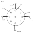
- the sound-source-search system shown in Fig. 1 compr i ses a baffle 10, microphones 11, amp 20, A/D converter 30, arithmetic-processing apparatus 40, memory apparatus 50, display apparatus 60, and input apparatus 70. It is possible for the arithmetic-processing apparatus 40, memory apparatus 50, display apparatus 60 and input apparatus 70 to be constructed using an electronic device such as a notebook computer or desktop computer.
- the baffle 10 is spherical. Also, the baffle 10 is installed at the top of a long member (not shown in the figure) such as a pole such that it is kept at a specified height from the ground plane.
- a plurality of microphones 11 is arranged on the surface of the baffle 10. It is possible to use dynamic microphones or condenser microphones as the microphones 11.
- the built-in main unit such as the pre-amp (not shown in the figure) for the microphones 11, and the microphone cables 11a that are connected to the main unit are installed inside the baffle 10.
- the radius of the baffle 10 shown in Fig. 1 is about 130 mm.
- the number of microphones 11 placed on the baffle 10 is 17.
- the number of microphones 11 can be the minimum number necessary to correspond to the dimensions for searching for a sound source, and it is possible to use 2 microphones when searching for a sound source in one dimension, 3 microphones when searching for a sound source in two dimensions, and 4 microphones when searching for a sound source in 3 dimensions.
- 17 microphones are used in order to improve precision and stability of the results of the sound-source search.
- the built-in main unit such as the pre-amp (not shown in the figure) for the microphones 11, and the microphone cables 11a that are connected to the main unit on the inside of the spherical baffle 10 in this way, it is possible to suppress disturbances in the sound field around the baffle 10, and thus it becomes possible to accurately pick up sound from the sound source.
- coordinates that indicate the position of each microphone 11 on the baffle 10 in three dimensions are set, and they are used when the arithmetic-processing apparatus 40 performs arithmetic operations in the sound-source search. By doing so, it becomes possible to identify from which microphone 11 a picked up sound is coming from.
- the amp 20 is an amplifier that amplifies the analog signals that are electrical signals of the sounds obtained in all directions by each of the microphones 11.
- the microphone cables 11a from each of the microphones 11 are connected to the amp 20.
- the A/D converter 30 converts the analog signal that was amplified by the amp 20 to a digital signal.
- the arithmetic-processing apparatus 40 performs operations on the digital signal converted by the A/D converter 30, and searches for the sound source by processing sound information picked up by each of the microphones 11 inclusively and as a whole.
- the sound-source search is analysing the direction from which the sound arrives from the sound source, and estimating the intensity of the sound from the sound source. The sound-source search will be explained in detail later.
- the memory apparatus 50 stores the results of the arithmetic processing by the arithmetic-processing apparatus 40.
- the memory apparatus 50 it is possible to use a magnetic-tape memory apparatus that uses magnetic tape as the recording medium, or an optical-disk memory apparatus that uses an optical disk as the recording medium.
- the display apparatus 60 displays the sound intensity distribution of the sound from the sound source based on the arithmetic processing results from the arithmetic-processing apparatus 40.
- the input apparatus 70 is used for entering the distance to the sound source or to sound sources generated at a plurality of sites on boundary surfaces such as walls in a room. It is possible to use a keyboard, touch panel or the like as the input apparatus. However, in the case where the purpose is to analyze the direction from which the sound comes, and calculate the acoustical contribution on the location of the baffle, and is not to estimate the intensity of the sound, it is possible to eliminate the input apparatus 70.
- the search for a sound source can be performed in either a large space or a small space.
- a large space it is preferable that there be no obstacles between the baffle 10 and the sound source being searched for: for example, in a location where a large number of people may congregate, the baffle 10 should be set at a high location where it over looks the ent i re space: or in a location such as an airport, the baffle 10 should be set in a location where no buildings or structures will become obstacles.
- the baffle 10 should be placed in a location where it can overlook the entire space.
- analysis information for the sound field which includes direct or diffracted sound around the baffle 10 is entered into the arithmetic-processing apparatus 40.
- each of the microphones 11 picks up the sound from the sound source.
- sound is basically picked up by each of the microphones 11 at the same time.
- the condition when not recording the sounds from all of the microphones at the same time is that the sound from the sound source must not change over time.
- the sound from all directions obtained by way of each of the microphones 11 enters the amp 20 as analog signals, and those signals are amplified by the amp 20 and output.
- the analog signals that are amplified by the amp 20 are converted to digital signals by the A/D converter 30 and then taken in by the arithmetic-processing apparatus 40.
- analysis of the sound picked up by each of the microphones 11 is performed by arithmetic processing.
- the amplitude characteristics and phase characteristics of each of the acoustic signals picked up by each of the microphones 11 are found by arithmetic processing.
- analysis information for the sound field around the baffle 10 described above is added, and arithmetic processing, which emphasizes the sound coming from a specified direction, is performed in all directions, making it possible to identify through arithmetic processing the direction from which the sound from the sound source comes.
- est i mat i ng the intensity of the sound from the sound source the distance d to the sound source shown in Fig. 2 is entered into the arithmetic-processing apparatus 40 from the input apparatus 70.
- the direction from which the sound from the sound source comes and the sound pressure are identified by the arithmetic-processing apparatus 40 as described above, so it is possible to estimate the intensity of the sound from the sound source through arithmetic processing from these ar i thmet i c process i ng results and the distance d to the sound source.
- est i mat i ng the intensity of the sound from the sound source by add i ng the distance d to the sound source to the conventional frequency domain beam forming method, it is possible to more accurately estimate the intensity of the sound from the sound source.
- the distance d to the sound source used for estimating the intensity of the sound from the sound source is input to the arithmetic-processing apparatus 40 from the input apparatus 70, however, of course it is also possible to enter the distance d to the sound source into the arithmetic-processing apparatus 40 from the input apparatus 70 before starting the sound-source search.
- Fig. 4 shows an example of the sound-intensity distribution that is displayed by the display apparatus 60.
- the size of the sound intensity is indicated, for example, by a to f (a > f > c > d > e > f).
- a plurality of microphones 11 are arranged on the surface of a spherical baffle 10 and sound is picked up from all directions in this way, and after the amplitude characteristics and phase characteristics of each of the acoustic signals picked up by the plurality of microphones 11 are found through arithmetic processing by the arithmetic-processing apparatus 40, that signal information is combined with the analysis information for the sound field around the baffle, and arithmetic processing to emphasize the sound coming from a specific direction is performed for all directions, and together with identifying the direction from which sound from the sound source comes through arithmetic processing, the intensity of the sound from the sound source or from sound sources generated at a plurality of sites on boundaries is estimated from the arithmetic processing results and the distance entered from the input apparatus 70, so regardless of whether or not the space is small, it is possible to identify the direction from which the sound from the sound source comes, and estimate the intensity of the sound from the sound source at the same time in all directions.
- set up work is very easy since it requires just setting a baffle 10 having a plurality of microphones 11 installed in place, and then connect i ng the microphone cables 11 a from the microphones 11 to the amp 20.
- the invention is not limited to this example, and it is possible for the baffle 10 to be semi-spherical or polyhedral. Any one of the cases is possible as long as analysis information for the diffracted sound around the baffle 10 can be obtained in some form. In this way, even when the baffle 10 is semi-spherical or polyhedral, the microphones 11 are built-in the baffle, so it is possible to suppress distortion in the sound field around the baffle 10, and thus it is possible to perform the sound-source search accurately.
- the material used for the baffle 10 can be any material, such as stainless steel, aluminum alloy, copper alloy or the like, that retains sufficient strength after a plurality of microphones 11 has been built in. It is possible to perform polishing or rough i ng of the surface of the baffle 10, and it is also possible to attach sound absorption material. In any case, as long as it is possible to obtain analysis information for diffracted sound around the baffle 10 due to the shape or material of the baffle 10, it is possible to accurately analyze the direction from which the sound from the sound source comes, and estimate the intensity of the sound source even though the shape and material of the baffle 10 may differ.
- Fig. 5 is a drawing showing a second embodiment in which one or more sound source elements for measuring distance are added to the baffle 10 shown in Fig. 1 .
- the same reference numbers are used for parts that are in common with those of Fig. 1 to Fig. 3 , and any redundant explanation will be omitted.
- Fig. 5 there are one or more sound-source elements 12 for measuring distance placed on the surface of the baffle 10 and they generate sound waves. It is possible to use directive or non-directive acoustical speakers or ultrasonic speakers as the sound-source elements 12 for measuring distance.
- test wave having a specific frequency as the sound wave from the sound-source element 12 for measur i ng distance
- random noise pseudo random noise
- M-sequence signal an M-sequence signal
- a frequency-sweep signal or the like to perform arithmetic processing and automatically measure the distance to sound sources at one or more sites. After measuring the distance to the sound source or sound sources generated at a plurality of sites on the boundary surfaces in this way, it is possible to more accurately analyze the direction from which sound from the sound source comes, and estimate the intensity of the sound from the sound source.
- Fig. 6 is a drawing showing a third embodiment in which one or more light-receiving elements are added to the baffle 10 shown in Fig. 5 .
- one or more light-receiving elements 13 are arranged on the surface of the baffle 10. It is possible to use a camera such as a CCD camera compr i s i ng a CCD (Charge Coupled Device) and lens, a laser-receiving element, infrared-ray-receiving element or the like as the light-receiving element 13.
- a camera such as a CCD camera compr i s i ng a CCD (Charge Coupled Device) and lens, a laser-receiving element, infrared-ray-receiving element or the like as the light-receiving element 13.
- each light-receiving element 13 be placed such that its imaging range overlaps that of the adjacent light-receiving elements.
- the image ranges Y overlap.
- a plurality of light-receiving elements 13 are arranged on the surface of the baff le 10 such that the image ranges overlap, it is possible to automatically take in an image of around the sound source or sound sources generated at a plurality of sites on the boundary surfaces that correspond to the direction from which a specific sound comes, and to display that obtained image in color by the display apparatus 60.
- Fig. 8 shows an example of the image displayed by the display apparatus 60.
- Fig. 10 is a drawing showing a fourth embodiment in which a plurality of light sources is added to the baffle 10 shown in Fig. 6 .
- a plurality of light sources 14 is arranged on the surface of the baffle 10. It is possible to use CCD-camera lighting, a laser pointer, a laser range finder, strobe or the like as the light source 14.
- a range finder such as a laser range finder
- light is emitted from the light source 14, and the reflected light of that light is received by the light-receiving unit 13, making it possible to automatically measure the distance to the boundary surface, which can be the baffle or sound source.
- the light generated by the light source 14 it is possible to light up the area of the sound source or sound sources generated at a plurality of sites on the boundary surfaces, so even in an area with dim lighting, it is possible to take good images with the light-receiving elements 13.
- Fig. 11 is a drawing explaining a fifth embodiment in which the light-receiving elements 13 shown in Fig. 6 automatically measure the distance to the sound source or sound sources generated at a plurality of sites on the boundary surfaces.
- Fig. 12 is a drawing showing a sixth embodiment in which, as an example of having a plurality of the baffles 10 shown in Fig. 6 , two baffles 10 are used.
- the distance to the sound source is even more accurately measured accord i ng to the theory of tr i angu lation, and of course, it is possible to more accurately measure the intensity of the sound from the sound source ; and compared with the case of us i ng on I y one baffle, when the number of microphones used is increased, the range of received sound is expanded, and it becomes possible to greatly improve the precision of the sound-source search.
- Fig. 13 is a drawing showing a seventh embodiment in which a plurality of satellite microphones is located on the baffle 10 shown in Fig. 1 .
- a plurality of satellite microphones 11A is arranged on the baffle 10.
- the arithmetic-processing apparatus 40 is able to use acoustic information from the satellite microphones in the sound-source search.
- the acoustic information from the satellite microphones 11 A be used in a form in which analysis information about the diffracted sound around the baffle 10 has been added.
- the satellite microphones 11A are located further outside than the baffle 10, and have the effect of virtually increasing the size of the baffle 10 without having to change the size of the baffle 10. Since the number of microphones that can be used in the sound-source search is increased, it becomes possible to greatly increase the precision of the sound-source search.
- one or more microphones are arranged on and/or near the surface of a spherical, semi-spherical or polyhedral baffle to p i ck up sound from all directions, and after an arithmetic-processing apparatus identifies the direction from wh i ch sound comes through ar i thmet i c process i ng that focuses on the amplitude characteristics and phase characteristics of the acoustic signals picked up by the plurality of microphones, the intensity of the sound from the sound source or sound sources generated at a plurality of sites on boundary surfaces is estimated from the arithmetic processing results and distances entered from an input apparatus or measured by sound-source, light-source or image processing, so regardless of whether or not the space is small, it is possible to identify the direction from which sound from the sound source comes, and to estimate the intensity of the sound source in all directions at the same time.
Landscapes
- Physics & Mathematics (AREA)
- Engineering & Computer Science (AREA)
- Otolaryngology (AREA)
- Health & Medical Sciences (AREA)
- Acoustics & Sound (AREA)
- Signal Processing (AREA)
- Radar, Positioning & Navigation (AREA)
- Remote Sensing (AREA)
- General Physics & Mathematics (AREA)
- General Health & Medical Sciences (AREA)
- Measurement Of Velocity Or Position Using Acoustic Or Ultrasonic Waves (AREA)
- Measurement Of Mechanical Vibrations Or Ultrasonic Waves (AREA)
- Obtaining Desirable Characteristics In Audible-Bandwidth Transducers (AREA)
- Information Retrieval, Db Structures And Fs Structures Therefor (AREA)
Claims (8)
- Schallquellensuchsystem, umfassend:eine kugelförmige, halbkugelförmige oder vielflächige Schallwand (10);eine Vielzahl von Mikrofonen (11), die auf der Oberfläche dieser Schallwand (10) angeordnet sind, um Schall in allen Richtungen aufzunehmen;einen Verstärker (20), der analoge Signale verstärkt, die elektrische Signale für alle Töne in allen Richtungen sind, die durch die Vielzahl der Mikrofone (11) aufgenommen wurden;einen A/D-Wandler (30), der die analogen Signale, die durch den Verstärker (20) verstärkt worden sind, in digitale Signale umwandelt;eine Arithmetikverarbeitungsvorrichtung (40), ausgelegt, um eine arithmetische Verarbeitung der digitalen Signale auszuführen, die durch den A/D-Wandler (30) umgewandelt worden sind, und ausgelegt, um jede Richtung zu analysieren, aus der der Schall von einer Schallquelle kommt, und/oder ausgelegt, um jede Intensität des Schalls von einer Schallquelle zu schätzen;eine Speichervorrichtung (50) für das Speichern der Ergebnisse der arithmetischen Verarbeitung durch die Arithmetikverarbeitungsvorrichtung (40);eine Anzeigevorrichtung (60), die die Intensitätsverteilung des Schalls von einer Schallquelle anzeigt, basierend auf den Ergebnissen der arithmetischen Verarbeitung durch die Arithmetikverarbeitungsvorrichtung (40); undeine Eingabevorrichtung (70) für das Eingeben der Distanz von der Schallwand (10) zu einer Schallquelle oder der Distanzen von der Schallwand (10) zu Schallquellen, die an einer Vielzahl von Orten auf Grenzflächen erzeugt werden; und wobeidie Arithmetikverarbeitungsvorrichtung (40) ausgelegt ist, um durch eine arithmetische Verarbeitung die Amplitudeneigenschaften und die Phaseneigenschaften jeder der akustischen Signale, die von der Vielzahl der Mikrophone aufgenommen wurden, als Signalinformation herauszufinden, und die ausgelegt ist, um diese Signalinformation mit Analyseinformation, die direkten oder gebeugten Schall des Schallfeldes um die Schallwand (10) herum einschließt, zu kombinieren, und die ausgelegt ist, um eine arithmetische Verarbeitung auszuführen, um den Schall, der aus einer spezifischen Richtung kommt, für alle Richtungen hervorzuheben, und um die Richtung, aus der der Schall kommt, zu identifizieren, und um die Intensität des Schalls von einer Schallquelle oder von Schallquellen zu schätzen, der an einem oder mehreren Orten auf den Grenzflächen erzeugt wird, basierend auf den Ergebnissen der arithmetischen Verarbeitung und der Distanz oder den Distanzen, die von der Eingabevorrichtung (70) eingegeben wird oder werden.
- Schallquellensuchsystem, umfassend:eine kugelförmige, halbkugelförmige oder vielflächige Schallwand (10);eine Vielzahl von Mikrofonen (11), die auf der Oberfläche dieser Schallwand (10) angeordnet sind, um Schall in allen Richtungen aufzunehmen;einen Verstärker (20), der analoge Signale verstärkt, die elektrische Signale für alle Töne in allen Richtungen sind, die durch die Vielzahl der Mikrofone (11) aufgenommen wurden;einen A/D-Wandler (30), der die analogen Signale, die durch den Verstärker (20) verstärkt worden sind, in digitale Signale umwandelt;eine Arithmetikverarbeitungsvorrichtung (40), ausgelegt, um eine arithmetische Verarbeitung der digitalen Signale auszuführen, die durch den A/D-Wandler (30) umgewandelt worden sind, und ausgelegt, um die Amplitudeneigenschaften und Phaseneigenschaften jeder der akustischen Signale, die durch die Vielzahl der Mikrofone (11) aufgenommen wurden, als Signalinformation zu finden, ausgelegt, um diese Signalinformation mit Analyseinformation des Schallfeldes um die Schallwand (10) herum zu kombinieren, und ausgelegt, um eine arithmetische Verarbeitung auszuführen, um den Schall, der aus einer spezifischen Richtung kommt, für alle Richtungen hervorzuheben, und ausgelegt, um die Richtung, aus der der Schall kommt, zu identifizieren, und die Intensität des Schalls von einer Schallquelle oder Schallquellen, der an einer oder mehreren Orten auf Grenzflächen erzeugt wird, zu schätzen, unter Verwendung des Wertes der Distanz oder der Distanzen zwischen der Schallwand (10) und einer Schallquelle oder Schallquellen als Information;eine Speichervorrichtung (50) für das Speichern der Ergebnisse der arithmetischen Verarbeitung durch die Arithmetikverarbeitungsvorrichtung (40);eine Anzeigevorrichtung (60), die die Intensitätsverteilung des Schalls von einer Schallquelle auf der Basis der arithmetischen Verarbeitung durch die Arithmetikverarbeitungsvorrichtung (40) anzeigt; undein oder mehrere gerichtete oder nicht gerichtete Schallquellenelemente (12), die Schallwellen als einen Testschall erzeugen, der mit dem Schall der einen oder mehreren externen Schallquellen nicht korreliert ist, und die auf der Oberfläche der Schallwand (10) angeordnet sind; wobeidie Arithmetikverarbeitungsvorrichtung ausgelegt ist, um durch eine arithmetische Verarbeitung die Amplitudeneigenschaften und die Phaseneigenschaften jeder der reflektierten Töne, die von der Vielzahl der Mikrophone (11) aufgenommen wurden, herauszufinden, nach dem Kombinieren dieser Signalinformation mit Analyseinformation vom Schallfeld um die Schallwand (10) herum, und ausgelegt, um eine arithmetische Verarbeitung auszuführen, um den Schall, der aus einer spezifischen Richtung kommt, für alle Richtungen hervorzuheben, und um die Richtung, aus der der reflektierte Schall kommt, zu identifizieren, und ausgelegt, um automatisch die Distanz oder die Distanzen von der Schallwand zur Schallquelle oder zu den Schallquellen, die an einer oder mehreren Orten auf Grenzflächen erzeugt werden, zu messen, durch die Verwendung der Zeitdifferenz vom Zeitpunkt, zu dem der Testschall erzeugt worden ist, bis zum Zeitpunkt, zu dem der reflektierte Schall aufgenommen wurde.
- Schallquellensuchsystem nach Anspruch 1 oder Anspruch 2, weiter umfassend ein oder mehrere Lichtempfangselemente (13), die auf der Oberfläche der Schallwand (10) so angeordnet sind, dass sich die Abbildungsbereiche überlappen; und wobei
die Arithmetikverarbeitungsvorrichtung (40) ausgelegt ist, um das Bild von einem oder mehreren der Lichtempfangselemente (13), das der identifizierten Richtung entspricht, aus der der spezifische Schall kommt, hereinzunehmen, und ausgelegt ist, um das Bild der Ankunftsrichtung und/oder die Intensität der Schallverteilung, die durch die arithmetische Verarbeitung gefunden wurde, mit dem Bild oder dem Ergebnis der Bildverarbeitung, die auf diesem Bild basiert, zu kombinieren und anzuzeigen. - Schallquellensuchsystem nach Anspruch 3, weiter eine oder mehrere Lichtquellen (14), die auf der Oberfläche der Schallwand (10) angeordnet sind, umfassend; und wobei
die Arithmetikverarbeitungsvorrichtung (40) ausgelegt ist, um automatisch die Distanz von der Schallwand (10) zu den Schallquellen, die an einer Vielzahl von Orten auf Grenzflächen erzeugt werden, zu messen, unter Verwendung der Zeit vom Zeitpunkt, zu dem das Licht erzeugt wurde, bis zum Zeitpunkt, zu dem das reflektierte Licht hereingenommen wurde, und die ausgelegt ist, um diesen Wert als Information zu verwenden, um die Intensität des Schalls von der Schallquelle oder den Schallquellen, der an einer oder mehreren Orten auf Grenzflächen erzeugt wird, zu schätzen. - Schallquellensuchsystem nach Anspruch 3 oder 4,
wobei die Arithmetikverarbeitungsvorrichtung (40) ausgelegt ist, um eine Bildverarbeitung auf dem Gebiet des Abbildungsbereiches der Lichtempfangselemente (13), die sich überlappen, auszuführen, und ausgelegt ist, um automatisch die Distanz zur Schallquelle oder den Schallquellen, die an einem oder mehreren Orten auf Grenzflächen erzeugt werden, zu messen. - Schallquellensuchsystem nach einem der Ansprüche 1 bis 5, umfassend eine Vielzahl von Schallwänden (10); und wobei
die Arithmetikverarbeitungsvorrichtung (40) ausgelegt ist, um zu finden: die Distanz von einer der Schallwände (10) zur Schallquelle oder den Schallquellen, die an einer oder mehreren Orten auf Grenzflächen erzeugt werden, und/oder die Richtung, aus der der Schall kommt; die Distanz von einer anderen der Schallwände (10) zur Schallquelle oder den Schallquellen, die an einem Ort oder mehreren Orten auf Grenzflächen erzeugt werden, und/oder die Richtung, aus der der Schall kommt; und die Positionsbeziehung zwischen den Schallwänden (10); und ausgelegt ist, um danach die Theorie der Triangulation zu verwenden, basierend auf dieser Information, um die Distanz zur Schallquelle oder den Schallquellen, die an einem Ort oder mehreren Orten auf Grenzflächen erzeugt werden, zu finden. - Schallquellensuchsystem nach einem der Ansprüche 1 bis 6, weiter umfassend ein oder mehrere Satellitenmikrofone (11A), die an Orten angeordnet sind, die sich getrennt von der Oberfläche der Schallwand (10) befinden; und wobei
die Arithmetikverarbeitungsvorrichtung (40) ausgelegt ist, um den Schall, der von der Vielzahl der Satellitenmikrofone (11A) aufgenommen wurde, zu verwenden, um die Richtung zu finden, aus der der Schall kommt und/oder die Intensität des Schalls von der Schallquelle. - Schallquellensuchvorrichtung nach einem der Ansprüche 1 bis 7, wobei die Schallwand (10) auf der Spitze eines langen Elements montiert ist, so dass diese in einer spezifischen Höhe über Grund gehalten wird.
Applications Claiming Priority (3)
| Application Number | Priority Date | Filing Date | Title |
|---|---|---|---|
| JP2002093025 | 2002-08-30 | ||
| JP2002293025 | 2002-08-30 | ||
| PCT/JP2003/010851 WO2004021031A1 (ja) | 2002-08-30 | 2003-08-27 | 音源探査システム |
Publications (3)
| Publication Number | Publication Date |
|---|---|
| EP1544635A1 EP1544635A1 (de) | 2005-06-22 |
| EP1544635A4 EP1544635A4 (de) | 2010-10-13 |
| EP1544635B1 true EP1544635B1 (de) | 2012-01-18 |
Family
ID=31973467
Family Applications (1)
| Application Number | Title | Priority Date | Filing Date |
|---|---|---|---|
| EP03791338A Expired - Lifetime EP1544635B1 (de) | 2002-08-30 | 2003-08-27 | Schallquellensuchsystem |
Country Status (8)
| Country | Link |
|---|---|
| US (1) | US7379553B2 (de) |
| EP (1) | EP1544635B1 (de) |
| JP (1) | JP4368798B2 (de) |
| KR (1) | KR101010099B1 (de) |
| AT (1) | ATE542149T1 (de) |
| AU (1) | AU2003261759A1 (de) |
| CA (1) | CA2496785C (de) |
| WO (1) | WO2004021031A1 (de) |
Families Citing this family (60)
| Publication number | Priority date | Publication date | Assignee | Title |
|---|---|---|---|---|
| FR2858403B1 (fr) * | 2003-07-31 | 2005-11-18 | Remy Henri Denis Bruno | Systeme et procede de determination d'une representation d'un champ acoustique |
| JP2006245725A (ja) * | 2005-03-01 | 2006-09-14 | Yamaha Corp | マイクロフォンシステム |
| JP4804095B2 (ja) * | 2005-10-07 | 2011-10-26 | パナソニック株式会社 | マイクロホン装置 |
| JP2007121045A (ja) * | 2005-10-26 | 2007-05-17 | Matsushita Electric Works Ltd | 超音波物体検知装置 |
| EP1983799B1 (de) | 2007-04-17 | 2010-07-07 | Harman Becker Automotive Systems GmbH | Akustische Lokalisierung eines Sprechers |
| JP5094377B2 (ja) * | 2007-12-28 | 2012-12-12 | 富士通コンポーネント株式会社 | Kvmスイッチ及び遠隔システム |
| US20110051952A1 (en) * | 2008-01-18 | 2011-03-03 | Shinji Ohashi | Sound source identifying and measuring apparatus, system and method |
| JP5686358B2 (ja) * | 2008-03-07 | 2015-03-18 | 学校法人日本大学 | 音源距離計測装置及びそれを用いた音響情報分離装置 |
| JP2010011433A (ja) * | 2008-05-30 | 2010-01-14 | Nittobo Acoustic Engineering Co Ltd | 音源分離及び表示方法並びにシステム |
| US8314829B2 (en) * | 2008-08-12 | 2012-11-20 | Microsoft Corporation | Satellite microphones for improved speaker detection and zoom |
| KR101064976B1 (ko) * | 2009-04-06 | 2011-09-15 | 한국과학기술원 | 음원위치추정시스템 및 이를 구비한 음원에 반응하는 로봇 |
| JP5350914B2 (ja) * | 2009-06-30 | 2013-11-27 | 西松建設株式会社 | 騒音監視システムおよび騒音監視方法 |
| JP5452158B2 (ja) * | 2009-10-07 | 2014-03-26 | 株式会社日立製作所 | 音響監視システム、及び音声集音システム |
| US8207453B2 (en) | 2009-12-17 | 2012-06-26 | Intel Corporation | Glass core substrate for integrated circuit devices and methods of making the same |
| US9420707B2 (en) | 2009-12-17 | 2016-08-16 | Intel Corporation | Substrate for integrated circuit devices including multi-layer glass core and methods of making the same |
| JP5390447B2 (ja) * | 2010-03-26 | 2014-01-15 | 株式会社高速道路総合技術研究所 | 騒音対策効果量の推計方法 |
| EP2375779A3 (de) | 2010-03-31 | 2012-01-18 | Fraunhofer-Gesellschaft zur Förderung der Angewandten Forschung e.V. | Vorrichtung und Verfahren zum Messen einer Vielzahl von Lautsprechern und Mikrofonanordnung |
| US9496841B2 (en) * | 2010-10-21 | 2016-11-15 | Nokia Technologies Oy | Recording level adjustment using a distance to a sound source |
| JP2012133250A (ja) | 2010-12-24 | 2012-07-12 | Sony Corp | 音情報表示装置、音情報表示方法およびプログラム |
| JP5016724B1 (ja) * | 2011-03-18 | 2012-09-05 | リオン株式会社 | 騒音観測装置及び騒音観測方法 |
| US9973848B2 (en) * | 2011-06-21 | 2018-05-15 | Amazon Technologies, Inc. | Signal-enhancing beamforming in an augmented reality environment |
| JP5642027B2 (ja) * | 2011-07-06 | 2014-12-17 | 株式会社日立パワーソリューションズ | 異音診断装置および異音診断方法 |
| WO2013015461A1 (ko) * | 2011-07-22 | 2013-01-31 | 엘지전자 주식회사 | 음원 방향 탐지 장치 및 이를 포함하는 감시 카메라 |
| US10319121B2 (en) * | 2011-12-01 | 2019-06-11 | Nittobo Acoustic Engineering Co., Ltd. | Acoustic performance calculation device, acoustic performance calculation method, and acoustic performance calculation program |
| KR101282673B1 (ko) | 2011-12-09 | 2013-07-05 | 현대자동차주식회사 | 음원 위치 추정 방법 |
| JP6031761B2 (ja) * | 2011-12-28 | 2016-11-24 | 富士ゼロックス株式会社 | 音声解析装置および音声解析システム |
| WO2013133827A1 (en) | 2012-03-07 | 2013-09-12 | Intel Corporation | Glass clad microelectronic substrate |
| CN102955148A (zh) * | 2012-11-04 | 2013-03-06 | 李良杰 | 球面红外线传感器阵列定向仪 |
| CN102968128A (zh) * | 2012-11-13 | 2013-03-13 | 李良杰 | 太阳方向获取装置 |
| US9042563B1 (en) * | 2014-04-11 | 2015-05-26 | John Beaty | System and method to localize sound and provide real-time world coordinates with communication |
| US9769552B2 (en) * | 2014-08-19 | 2017-09-19 | Apple Inc. | Method and apparatus for estimating talker distance |
| US10909384B2 (en) * | 2015-07-14 | 2021-02-02 | Panasonic Intellectual Property Management Co., Ltd. | Monitoring system and monitoring method |
| CN105116406B (zh) * | 2015-09-30 | 2018-11-30 | 长沙开山斧智能科技有限公司 | 一种复合测距仪及其测距方法 |
| JP6747451B2 (ja) * | 2015-11-17 | 2020-08-26 | ソニー株式会社 | 情報処理装置、情報処理方法、及びプログラム |
| JP2017102085A (ja) * | 2015-12-04 | 2017-06-08 | キヤノン株式会社 | 情報処理装置、情報処理方法及びプログラム |
| CN107290711A (zh) * | 2016-03-30 | 2017-10-24 | 芋头科技(杭州)有限公司 | 一种语音寻向系统及方法 |
| CN107402571A (zh) * | 2016-05-20 | 2017-11-28 | 富泰华工业(深圳)有限公司 | 声音强度定位引导系统及方法 |
| US10070238B2 (en) | 2016-09-13 | 2018-09-04 | Walmart Apollo, Llc | System and methods for identifying an action of a forklift based on sound detection |
| WO2018052787A1 (en) | 2016-09-13 | 2018-03-22 | Walmart Apollo, Llc | System and methods for estimating storage capacity and identifying actions based on sound detection |
| CN106954126B (zh) * | 2017-03-31 | 2020-01-10 | 深圳壹秘科技有限公司 | 一种音频信息处理方法及其会议终端 |
| US20190129027A1 (en) | 2017-11-02 | 2019-05-02 | Fluke Corporation | Multi-modal acoustic imaging tool |
| US11209306B2 (en) | 2017-11-02 | 2021-12-28 | Fluke Corporation | Portable acoustic imaging tool with scanning and analysis capability |
| CN109830998A (zh) * | 2017-11-23 | 2019-05-31 | 富泰华工业(深圳)有限公司 | 回充装置 |
| JP7072186B2 (ja) * | 2018-02-08 | 2022-05-20 | 株式会社オーディオテクニカ | マイクロホン装置及びマイクロホン装置用ケース |
| CN108389571A (zh) * | 2018-04-11 | 2018-08-10 | 李良杰 | 主动降噪装置 |
| US10951859B2 (en) | 2018-05-30 | 2021-03-16 | Microsoft Technology Licensing, Llc | Videoconferencing device and method |
| EP3827228A1 (de) | 2018-07-24 | 2021-06-02 | Fluke Corporation | Systeme und verfahren für lösbare und befestigbare akustische bildgebungssensoren |
| JP2020036215A (ja) | 2018-08-30 | 2020-03-05 | Tdk株式会社 | Memsマイクロフォン |
| JP2020036214A (ja) | 2018-08-30 | 2020-03-05 | Tdk株式会社 | Memsマイクロフォン |
| US11795032B2 (en) | 2018-11-13 | 2023-10-24 | Otis Elevator Company | Monitoring system |
| JP7245034B2 (ja) * | 2018-11-27 | 2023-03-23 | キヤノン株式会社 | 信号処理装置、信号処理方法およびプログラム |
| EP3662976B1 (de) | 2018-12-05 | 2022-06-01 | Marioff Corporation OY | Risserkennungsfunktion für eine sprinkleranlage mit zerbrechlichem kolben |
| KR102207070B1 (ko) * | 2019-07-16 | 2021-01-22 | 동명대학교산학협력단 | 잔향수조에서의 음원 지향성 산정에 적용하는 간이추정방법 |
| WO2021064917A1 (ja) * | 2019-10-02 | 2021-04-08 | 日本電信電話株式会社 | 関係決定装置、方法及びプログラム |
| KR20220041432A (ko) | 2020-09-25 | 2022-04-01 | 삼성전자주식회사 | 음향 신호를 이용한 거리 측정 시스템 및 방법 |
| US11418873B2 (en) | 2020-11-03 | 2022-08-16 | Edward J. Simon | Surveillance microphone |
| CN114577330B (zh) * | 2022-01-29 | 2025-03-25 | 中国船舶重工集团公司第七一五研究所 | 一种基于球型换能器表面测振的水下远场声场测量系统 |
| CN115240678B (zh) * | 2022-09-21 | 2022-12-09 | 深圳市英特飞电子有限公司 | 一种智能语音识别装置 |
| WO2025122290A1 (en) * | 2023-12-08 | 2025-06-12 | Fluke Corporation | Acoustic imaging system with rotational speed detection |
| DE102024108768A1 (de) * | 2024-03-27 | 2025-10-02 | Bayerische Motoren Werke Aktiengesellschaft | Verfahren zum Bestimmen zumindest einer Messposition für zumindest einen Sensor an einem elektrischen Motor für ein Kraftfahrzeug mittels einer Messvorrichtung, Computerprogrammprodukt, sowie Messvorrichtung |
Family Cites Families (15)
| Publication number | Priority date | Publication date | Assignee | Title |
|---|---|---|---|---|
| US4496022A (en) * | 1983-02-22 | 1985-01-29 | Prohs John R | System for interrelating sound transducers or sound sources and their environment |
| JPH0726887B2 (ja) * | 1986-05-31 | 1995-03-29 | 株式会社堀場製作所 | コンデンサマイクロフオン型検出器用ダイアフラム |
| JPH0472525A (ja) * | 1990-07-13 | 1992-03-06 | Nippon Telegr & Teleph Corp <Ntt> | 音源方向識別センサ |
| JPH06113387A (ja) | 1992-09-25 | 1994-04-22 | Railway Technical Res Inst | 音源観測用音像可視化装置 |
| JPH0737908B2 (ja) * | 1993-03-02 | 1995-04-26 | 日本電気株式会社 | 移動体騒音監視システム |
| US5717656A (en) * | 1996-08-20 | 1998-02-10 | Ybm Technologies, Inc. | Method and apparatus for detecting and locating a concealed listening device |
| JPH10332807A (ja) * | 1997-06-05 | 1998-12-18 | Fujitsu Ltd | 音源方向検出装置 |
| JPH1164089A (ja) * | 1997-08-18 | 1999-03-05 | Toshiba Corp | 波動診断装置 |
| JP4815661B2 (ja) * | 2000-08-24 | 2011-11-16 | ソニー株式会社 | 信号処理装置及び信号処理方法 |
| JP4868671B2 (ja) | 2001-09-27 | 2012-02-01 | 中部電力株式会社 | 音源探査システム |
| CA2393094C (en) * | 2000-10-02 | 2009-04-07 | Chubu Electric Power Co., Inc. | Sound source locating system |
| JP4722347B2 (ja) | 2000-10-02 | 2011-07-13 | 中部電力株式会社 | 音源探査システム |
| US7039198B2 (en) * | 2000-11-10 | 2006-05-02 | Quindi | Acoustic source localization system and method |
| US6978030B2 (en) * | 2001-09-13 | 2005-12-20 | Reich Ronald S | Light emitting loudspeaker cover |
| US20030147539A1 (en) * | 2002-01-11 | 2003-08-07 | Mh Acoustics, Llc, A Delaware Corporation | Audio system based on at least second-order eigenbeams |
-
2003
- 2003-08-27 EP EP03791338A patent/EP1544635B1/de not_active Expired - Lifetime
- 2003-08-27 AU AU2003261759A patent/AU2003261759A1/en not_active Abandoned
- 2003-08-27 KR KR1020057003061A patent/KR101010099B1/ko not_active Expired - Fee Related
- 2003-08-27 AT AT03791338T patent/ATE542149T1/de active
- 2003-08-27 CA CA2496785A patent/CA2496785C/en not_active Expired - Fee Related
- 2003-08-27 US US10/525,908 patent/US7379553B2/en not_active Expired - Lifetime
- 2003-08-27 WO PCT/JP2003/010851 patent/WO2004021031A1/ja not_active Ceased
- 2003-08-27 JP JP2004532729A patent/JP4368798B2/ja not_active Expired - Lifetime
Also Published As
| Publication number | Publication date |
|---|---|
| CA2496785A1 (en) | 2004-03-11 |
| WO2004021031A1 (ja) | 2004-03-11 |
| AU2003261759A1 (en) | 2004-03-19 |
| JP4368798B2 (ja) | 2009-11-18 |
| JPWO2004021031A1 (ja) | 2005-12-22 |
| EP1544635A1 (de) | 2005-06-22 |
| EP1544635A4 (de) | 2010-10-13 |
| KR101010099B1 (ko) | 2011-01-24 |
| US7379553B2 (en) | 2008-05-27 |
| ATE542149T1 (de) | 2012-02-15 |
| US20050246167A1 (en) | 2005-11-03 |
| CA2496785C (en) | 2011-11-22 |
| KR20050058467A (ko) | 2005-06-16 |
Similar Documents
| Publication | Publication Date | Title |
|---|---|---|
| EP1544635B1 (de) | Schallquellensuchsystem | |
| JP2011015050A (ja) | ビームフォーミング用のアレイ、及びそれを用いた音源探査測定システム | |
| Ginn et al. | Noise source identification techniques: simple to advanced applications | |
| CN1952684A (zh) | 利用麦克风定位声源的方法和装置 | |
| US9557400B2 (en) | 3D soundscaping | |
| JPWO2006054599A1 (ja) | 音源方向判定装置及び方法 | |
| Atmoko et al. | Accurate sound source localization in a reverberant environment using multiple acoustic sensors | |
| JP4248458B2 (ja) | 音圧測定方法 | |
| Prezelj et al. | A novel approach to localization of environmental noise sources: Sub-windowing for time domain beamforming | |
| JP2004085201A (ja) | 振動源探査システム | |
| KR20090128221A (ko) | 음원 위치 추정 방법 및 그 방법에 따른 시스템 | |
| Yadav et al. | Study of MVDR beamformer for a single acoustic vector sensor | |
| JP2005181088A (ja) | モーションキャプチャシステム及びモーションキャプチャ方法 | |
| CN112119642B (zh) | 用于探测和定位低强度和低频声源的声学系统及相关定位方法 | |
| CN119535358A (zh) | 一种阵列式多通道声学成像装置及异常声源定位显示方法 | |
| Shimoyama et al. | Acoustic source localization using phase difference spectrum images | |
| KR102180229B1 (ko) | 음원 위치 추정장치 및 이를 포함하는 로봇 | |
| JP2022123797A (ja) | 異常音発生箇所探査システム | |
| KR20060124443A (ko) | 머리전달함수 데이터베이스를 이용한 음원 위치 추정 방법 | |
| CN115184868B (zh) | 一种定位噪声源三维位置的方法 | |
| US20070025563A1 (en) | Snapshot of noise and acoustic propagation | |
| EP4565863A1 (de) | Diagnosesystem für fahrzeugkomponenten | |
| Parr et al. | Development of a Hand-held 3D Scanning Acoustic Camera | |
| Wu et al. | Locating Multiple Incoherent Sound Sources in 3D Space in Real Time | |
| Christensen et al. | A review of array techniques for noise source location |
Legal Events
| Date | Code | Title | Description |
|---|---|---|---|
| PUAI | Public reference made under article 153(3) epc to a published international application that has entered the european phase |
Free format text: ORIGINAL CODE: 0009012 |
|
| 17P | Request for examination filed |
Effective date: 20050210 |
|
| AK | Designated contracting states |
Kind code of ref document: A1 Designated state(s): AT BE BG CH CY CZ DE DK EE ES FI FR GB GR HU IE IT LI LU MC NL PT RO SE SI SK TR |
|
| AX | Request for extension of the european patent |
Extension state: AL LT LV MK |
|
| DAX | Request for extension of the european patent (deleted) | ||
| A4 | Supplementary search report drawn up and despatched |
Effective date: 20100909 |
|
| 17Q | First examination report despatched |
Effective date: 20101202 |
|
| RIC1 | Information provided on ipc code assigned before grant |
Ipc: H04R 3/00 20060101ALI20110617BHEP Ipc: G01S 3/80 20060101AFI20110617BHEP |
|
| GRAP | Despatch of communication of intention to grant a patent |
Free format text: ORIGINAL CODE: EPIDOSNIGR1 |
|
| GRAS | Grant fee paid |
Free format text: ORIGINAL CODE: EPIDOSNIGR3 |
|
| GRAA | (expected) grant |
Free format text: ORIGINAL CODE: 0009210 |
|
| AK | Designated contracting states |
Kind code of ref document: B1 Designated state(s): AT BE BG CH CY CZ DE DK EE ES FI FR GB GR HU IE IT LI LU MC NL PT RO SE SI SK TR |
|
| REG | Reference to a national code |
Ref country code: GB Ref legal event code: FG4D |
|
| REG | Reference to a national code |
Ref country code: DE Ref legal event code: R081 Ref document number: 60339784 Country of ref document: DE Owner name: NIHON ONKYO ENGINEERING CO., LTD., JP Free format text: FORMER OWNER: NITTOBO ACOUSTIC ENGINEERING CO. LTD., TOKIO/TOKYO, JP |
|
| REG | Reference to a national code |
Ref country code: CH Ref legal event code: EP |
|
| REG | Reference to a national code |
Ref country code: IE Ref legal event code: FG4D Ref country code: AT Ref legal event code: REF Ref document number: 542149 Country of ref document: AT Kind code of ref document: T Effective date: 20120215 |
|
| REG | Reference to a national code |
Ref country code: DE Ref legal event code: R096 Ref document number: 60339784 Country of ref document: DE Effective date: 20120315 |
|
| REG | Reference to a national code |
Ref country code: NL Ref legal event code: VDEP Effective date: 20120118 |
|
| PG25 | Lapsed in a contracting state [announced via postgrant information from national office to epo] |
Ref country code: NL Free format text: LAPSE BECAUSE OF FAILURE TO SUBMIT A TRANSLATION OF THE DESCRIPTION OR TO PAY THE FEE WITHIN THE PRESCRIBED TIME-LIMIT Effective date: 20120118 Ref country code: BE Free format text: LAPSE BECAUSE OF FAILURE TO SUBMIT A TRANSLATION OF THE DESCRIPTION OR TO PAY THE FEE WITHIN THE PRESCRIBED TIME-LIMIT Effective date: 20120118 Ref country code: BG Free format text: LAPSE BECAUSE OF FAILURE TO SUBMIT A TRANSLATION OF THE DESCRIPTION OR TO PAY THE FEE WITHIN THE PRESCRIBED TIME-LIMIT Effective date: 20120418 |
|
| PG25 | Lapsed in a contracting state [announced via postgrant information from national office to epo] |
Ref country code: FI Free format text: LAPSE BECAUSE OF FAILURE TO SUBMIT A TRANSLATION OF THE DESCRIPTION OR TO PAY THE FEE WITHIN THE PRESCRIBED TIME-LIMIT Effective date: 20120118 Ref country code: GR Free format text: LAPSE BECAUSE OF FAILURE TO SUBMIT A TRANSLATION OF THE DESCRIPTION OR TO PAY THE FEE WITHIN THE PRESCRIBED TIME-LIMIT Effective date: 20120419 Ref country code: PT Free format text: LAPSE BECAUSE OF FAILURE TO SUBMIT A TRANSLATION OF THE DESCRIPTION OR TO PAY THE FEE WITHIN THE PRESCRIBED TIME-LIMIT Effective date: 20120518 |
|
| REG | Reference to a national code |
Ref country code: AT Ref legal event code: MK05 Ref document number: 542149 Country of ref document: AT Kind code of ref document: T Effective date: 20120118 |
|
| PG25 | Lapsed in a contracting state [announced via postgrant information from national office to epo] |
Ref country code: CY Free format text: LAPSE BECAUSE OF FAILURE TO SUBMIT A TRANSLATION OF THE DESCRIPTION OR TO PAY THE FEE WITHIN THE PRESCRIBED TIME-LIMIT Effective date: 20120118 |
|
| PG25 | Lapsed in a contracting state [announced via postgrant information from national office to epo] |
Ref country code: SE Free format text: LAPSE BECAUSE OF FAILURE TO SUBMIT A TRANSLATION OF THE DESCRIPTION OR TO PAY THE FEE WITHIN THE PRESCRIBED TIME-LIMIT Effective date: 20120118 Ref country code: RO Free format text: LAPSE BECAUSE OF FAILURE TO SUBMIT A TRANSLATION OF THE DESCRIPTION OR TO PAY THE FEE WITHIN THE PRESCRIBED TIME-LIMIT Effective date: 20120118 Ref country code: SI Free format text: LAPSE BECAUSE OF FAILURE TO SUBMIT A TRANSLATION OF THE DESCRIPTION OR TO PAY THE FEE WITHIN THE PRESCRIBED TIME-LIMIT Effective date: 20120118 Ref country code: EE Free format text: LAPSE BECAUSE OF FAILURE TO SUBMIT A TRANSLATION OF THE DESCRIPTION OR TO PAY THE FEE WITHIN THE PRESCRIBED TIME-LIMIT Effective date: 20120118 Ref country code: CZ Free format text: LAPSE BECAUSE OF FAILURE TO SUBMIT A TRANSLATION OF THE DESCRIPTION OR TO PAY THE FEE WITHIN THE PRESCRIBED TIME-LIMIT Effective date: 20120118 Ref country code: DK Free format text: LAPSE BECAUSE OF FAILURE TO SUBMIT A TRANSLATION OF THE DESCRIPTION OR TO PAY THE FEE WITHIN THE PRESCRIBED TIME-LIMIT Effective date: 20120118 |
|
| PLBE | No opposition filed within time limit |
Free format text: ORIGINAL CODE: 0009261 |
|
| STAA | Information on the status of an ep patent application or granted ep patent |
Free format text: STATUS: NO OPPOSITION FILED WITHIN TIME LIMIT |
|
| PG25 | Lapsed in a contracting state [announced via postgrant information from national office to epo] |
Ref country code: SK Free format text: LAPSE BECAUSE OF FAILURE TO SUBMIT A TRANSLATION OF THE DESCRIPTION OR TO PAY THE FEE WITHIN THE PRESCRIBED TIME-LIMIT Effective date: 20120118 Ref country code: IT Free format text: LAPSE BECAUSE OF FAILURE TO SUBMIT A TRANSLATION OF THE DESCRIPTION OR TO PAY THE FEE WITHIN THE PRESCRIBED TIME-LIMIT Effective date: 20120118 |
|
| 26N | No opposition filed |
Effective date: 20121019 |
|
| PG25 | Lapsed in a contracting state [announced via postgrant information from national office to epo] |
Ref country code: AT Free format text: LAPSE BECAUSE OF FAILURE TO SUBMIT A TRANSLATION OF THE DESCRIPTION OR TO PAY THE FEE WITHIN THE PRESCRIBED TIME-LIMIT Effective date: 20120118 |
|
| REG | Reference to a national code |
Ref country code: DE Ref legal event code: R097 Ref document number: 60339784 Country of ref document: DE Effective date: 20121019 |
|
| REG | Reference to a national code |
Ref country code: CH Ref legal event code: PL |
|
| PG25 | Lapsed in a contracting state [announced via postgrant information from national office to epo] |
Ref country code: MC Free format text: LAPSE BECAUSE OF NON-PAYMENT OF DUE FEES Effective date: 20120831 |
|
| GBPC | Gb: european patent ceased through non-payment of renewal fee |
Effective date: 20120827 |
|
| PG25 | Lapsed in a contracting state [announced via postgrant information from national office to epo] |
Ref country code: LI Free format text: LAPSE BECAUSE OF NON-PAYMENT OF DUE FEES Effective date: 20120831 Ref country code: CH Free format text: LAPSE BECAUSE OF NON-PAYMENT OF DUE FEES Effective date: 20120831 Ref country code: ES Free format text: LAPSE BECAUSE OF FAILURE TO SUBMIT A TRANSLATION OF THE DESCRIPTION OR TO PAY THE FEE WITHIN THE PRESCRIBED TIME-LIMIT Effective date: 20120429 |
|
| REG | Reference to a national code |
Ref country code: FR Ref legal event code: ST Effective date: 20130430 |
|
| REG | Reference to a national code |
Ref country code: IE Ref legal event code: MM4A |
|
| PG25 | Lapsed in a contracting state [announced via postgrant information from national office to epo] |
Ref country code: GB Free format text: LAPSE BECAUSE OF NON-PAYMENT OF DUE FEES Effective date: 20120827 Ref country code: IE Free format text: LAPSE BECAUSE OF NON-PAYMENT OF DUE FEES Effective date: 20120827 |
|
| PG25 | Lapsed in a contracting state [announced via postgrant information from national office to epo] |
Ref country code: FR Free format text: LAPSE BECAUSE OF NON-PAYMENT OF DUE FEES Effective date: 20120831 |
|
| PG25 | Lapsed in a contracting state [announced via postgrant information from national office to epo] |
Ref country code: TR Free format text: LAPSE BECAUSE OF FAILURE TO SUBMIT A TRANSLATION OF THE DESCRIPTION OR TO PAY THE FEE WITHIN THE PRESCRIBED TIME-LIMIT Effective date: 20120118 |
|
| PG25 | Lapsed in a contracting state [announced via postgrant information from national office to epo] |
Ref country code: LU Free format text: LAPSE BECAUSE OF NON-PAYMENT OF DUE FEES Effective date: 20120827 |
|
| PG25 | Lapsed in a contracting state [announced via postgrant information from national office to epo] |
Ref country code: HU Free format text: LAPSE BECAUSE OF FAILURE TO SUBMIT A TRANSLATION OF THE DESCRIPTION OR TO PAY THE FEE WITHIN THE PRESCRIBED TIME-LIMIT Effective date: 20030827 |
|
| REG | Reference to a national code |
Ref country code: DE Ref legal event code: R082 Ref document number: 60339784 Country of ref document: DE Representative=s name: MOEBUS, STEFFEN, DIPL.-ING., DE Ref country code: DE Ref legal event code: R081 Ref document number: 60339784 Country of ref document: DE Owner name: NIHON ONKYO ENGINEERING CO., LTD., JP Free format text: FORMER OWNER: NITTOBO ACOUSTIC ENGINEERING CO. LTD., TOKIO/TOKYO, JP |
|
| PGFP | Annual fee paid to national office [announced via postgrant information from national office to epo] |
Ref country code: DE Payment date: 20160823 Year of fee payment: 14 |
|
| REG | Reference to a national code |
Ref country code: DE Ref legal event code: R119 Ref document number: 60339784 Country of ref document: DE |
|
| PG25 | Lapsed in a contracting state [announced via postgrant information from national office to epo] |
Ref country code: DE Free format text: LAPSE BECAUSE OF NON-PAYMENT OF DUE FEES Effective date: 20180301 |