EP1544635B1 - Sound source search system - Google Patents
Sound source search system Download PDFInfo
- Publication number
- EP1544635B1 EP1544635B1 EP03791338A EP03791338A EP1544635B1 EP 1544635 B1 EP1544635 B1 EP 1544635B1 EP 03791338 A EP03791338 A EP 03791338A EP 03791338 A EP03791338 A EP 03791338A EP 1544635 B1 EP1544635 B1 EP 1544635B1
- Authority
- EP
- European Patent Office
- Prior art keywords
- sound
- source
- baffle
- arithmetic
- microphones
- Prior art date
- Legal status (The legal status is an assumption and is not a legal conclusion. Google has not performed a legal analysis and makes no representation as to the accuracy of the status listed.)
- Expired - Lifetime
Links
- 238000009826 distribution Methods 0.000 claims description 12
- 238000003384 imaging method Methods 0.000 claims description 5
- 230000002596 correlated effect Effects 0.000 claims 1
- 238000000034 method Methods 0.000 description 13
- 238000010276 construction Methods 0.000 description 6
- 239000000463 material Substances 0.000 description 5
- 230000000694 effects Effects 0.000 description 3
- 238000009434 installation Methods 0.000 description 2
- 229910000838 Al alloy Inorganic materials 0.000 description 1
- 229910000881 Cu alloy Inorganic materials 0.000 description 1
- 206010047571 Visual impairment Diseases 0.000 description 1
- 238000010521 absorption reaction Methods 0.000 description 1
- 230000005534 acoustic noise Effects 0.000 description 1
- 210000001217 buttock Anatomy 0.000 description 1
- 230000001419 dependent effect Effects 0.000 description 1
- 238000001514 detection method Methods 0.000 description 1
- 150000002500 ions Chemical class 0.000 description 1
- 230000003287 optical effect Effects 0.000 description 1
- 238000005498 polishing Methods 0.000 description 1
- 239000010935 stainless steel Substances 0.000 description 1
- 229910001220 stainless steel Inorganic materials 0.000 description 1
- 239000000126 substance Substances 0.000 description 1
Images


Classifications
-
- H—ELECTRICITY
- H04—ELECTRIC COMMUNICATION TECHNIQUE
- H04R—LOUDSPEAKERS, MICROPHONES, GRAMOPHONE PICK-UPS OR LIKE ACOUSTIC ELECTROMECHANICAL TRANSDUCERS; DEAF-AID SETS; PUBLIC ADDRESS SYSTEMS
- H04R3/00—Circuits for transducers, loudspeakers or microphones
- H04R3/005—Circuits for transducers, loudspeakers or microphones for combining the signals of two or more microphones
-
- G—PHYSICS
- G01—MEASURING; TESTING
- G01H—MEASUREMENT OF MECHANICAL VIBRATIONS OR ULTRASONIC, SONIC OR INFRASONIC WAVES
- G01H3/00—Measuring characteristics of vibrations by using a detector in a fluid
- G01H3/10—Amplitude; Power
- G01H3/12—Amplitude; Power by electric means
- G01H3/125—Amplitude; Power by electric means for representing acoustic field distribution
-
- G—PHYSICS
- G01—MEASURING; TESTING
- G01S—RADIO DIRECTION-FINDING; RADIO NAVIGATION; DETERMINING DISTANCE OR VELOCITY BY USE OF RADIO WAVES; LOCATING OR PRESENCE-DETECTING BY USE OF THE REFLECTION OR RERADIATION OF RADIO WAVES; ANALOGOUS ARRANGEMENTS USING OTHER WAVES
- G01S3/00—Direction-finders for determining the direction from which infrasonic, sonic, ultrasonic, or electromagnetic waves, or particle emission, not having a directional significance, are being received
- G01S3/80—Direction-finders for determining the direction from which infrasonic, sonic, ultrasonic, or electromagnetic waves, or particle emission, not having a directional significance, are being received using ultrasonic, sonic or infrasonic waves
- G01S3/802—Systems for determining direction or deviation from predetermined direction
- G01S3/808—Systems for determining direction or deviation from predetermined direction using transducers spaced apart and measuring phase or time difference between signals therefrom, i.e. path-difference systems
- G01S3/8083—Systems for determining direction or deviation from predetermined direction using transducers spaced apart and measuring phase or time difference between signals therefrom, i.e. path-difference systems determining direction of source
-
- H—ELECTRICITY
- H04—ELECTRIC COMMUNICATION TECHNIQUE
- H04R—LOUDSPEAKERS, MICROPHONES, GRAMOPHONE PICK-UPS OR LIKE ACOUSTIC ELECTROMECHANICAL TRANSDUCERS; DEAF-AID SETS; PUBLIC ADDRESS SYSTEMS
- H04R1/00—Details of transducers, loudspeakers or microphones
- H04R1/20—Arrangements for obtaining desired frequency or directional characteristics
- H04R1/32—Arrangements for obtaining desired frequency or directional characteristics for obtaining desired directional characteristic only
- H04R1/40—Arrangements for obtaining desired frequency or directional characteristics for obtaining desired directional characteristic only by combining a number of identical transducers
- H04R1/406—Arrangements for obtaining desired frequency or directional characteristics for obtaining desired directional characteristic only by combining a number of identical transducers microphones
-
- H—ELECTRICITY
- H04—ELECTRIC COMMUNICATION TECHNIQUE
- H04R—LOUDSPEAKERS, MICROPHONES, GRAMOPHONE PICK-UPS OR LIKE ACOUSTIC ELECTROMECHANICAL TRANSDUCERS; DEAF-AID SETS; PUBLIC ADDRESS SYSTEMS
- H04R2201/00—Details of transducers, loudspeakers or microphones covered by H04R1/00 but not provided for in any of its subgroups
- H04R2201/40—Details of arrangements for obtaining desired directional characteristic by combining a number of identical transducers covered by H04R1/40 but not provided for in any of its subgroups
- H04R2201/401—2D or 3D arrays of transducers
Abstract
Description
- This invention relates to a sound-source-search system that searches for a sound source such as acoustic noise, and more particularly to a sound-source-search system in which a plurality of microphones are arranged at locations on a spherical, semi-spherical or polyhedral baffle surface and/or location separated from the surface, and processes the electrical signals from the sounds obtained from each of the microphones, and estimates the direction from wh i ch the sound comes and i ntens i ty of the sound source from all directions.
- In an electric generation plant, chemical plant, factory having an assembly line, or the like, acoustical noise that is generated from var i ous equipment and machinery such as motors, pumps, fans, transformers, etc., are combined and reach bordering areas or nearby homes. Also, inside transportation means such as automobiles, trains, airplanes, acoustical noises that are generated by the various components such as engines, gears, fans, and the like are combined and inhibit silence inside. Moreover, in normal housing areas such as apartments, and the like, silence inside is i nh i b i ted by var i ous no i ses. In order to solve the problems posed by these acoustical noises, it is necessary to accurately know the direction from which the sound is coming, and the intensity of the sound source.
- Conventionally, a sound source was searched for by placing a plurality of microphones over a wide area, recording the acoustical signals obtained by way of those microphones by a recording device such as a tape recorder and processing each of the recorded acoustical signals. However, in this kind of method of searching for a sound source, not only was it necessary to set up a plurality of microphones over a wide area, it was also necessary to wire each of the microphones to a recording device, so the set up work was very complicated.
- Also, as a different sound-source-search method is the sound-source-search apparatus disclosed, for example, in Japanese Patent Publication No.
H06-113387 - In order to solve this problem, in Japanese Patent Publication No.
2003-111183 - However, in Japanese Patent Publication No.
2003-111183 - Holographic imaging of sound fields produced by vehicles using planar array of microphones is known from the article by VAUCHER et al: "Holographie Acoustique Appliquée à des Mesures Intérieures 3D en Habitacle", Ingénieurs de l'Automobile- Editions-VB, Garches, FR, Nr. 741, pages 132-136,139, 1 November 2000, XP000987553.
- Taking into consideration the problems described above, the object of this invention is to provide a sound-source-search system that is not limited to a small space and is capable of identifying the direction from wh i ch sound is coming and the intensity of the sound source in all directions at the same time.
- A sound-source search system according to the present invention for solving the above problems is defined in
claims -
-
Fig. 1 is a drawing for explaining the basic construction of a first embodiment of the sound-source-search system of the invention. -
Fig. 2 is a drawing for explaining the sound-source-search method of the sound-source-search system shown inFig. 1 . -
Fig. 3 is a drawing for explaining the sound-source-search method of the sound-source-search system shown inFig. 1 . -
Fig. 4 is a drawing showing an example of the sound intensity distribution shown on the first display apparatus. -
Fig. 5 is a drawing showing a second embodiment in which one or more sound-source elements for measuring distance are added to the baffle shown inFig. 1 . -
Fig. 6 is a drawing showing a third embodiment in which one or more light-receiving elements are added to the baffle shown inFig. 5 . -
Fig. 7 is a drawing for explaining the operation of the one or more light-receiving elements shown inFig. 6 . -
Fig. 8 is a drawing showing an example of the image displayed in color on the display apparatus shown inFig. 6 . -
Fig. 9A, 9B and 9C are drawings showing an example of the image displayed in color on the display apparatus shown inFig. 6 . -
Fig. 10 is a drawing showing a fourth embodiment in which one or more light sources are added to the baffle shown inFig. 6 . -
Fig. 11 is a drawing for explaining a fifth embodiment in which the distances to sound sources or sound sources generated at one or more sites on the boundary surface are automatically measured by the light-receiving elements of the baffle shown inFig. 6 . -
Fig. 12 is a drawing showing a sixth embodiment in which two baffles as shown inFig. 6 are used. -
Fig. 13 is a drawing showing a seventh embodiment in which one or more satellite microphones are located on the baffle shown inFig. 1 . - The preferred embodiments of the invention will be explained below.
-
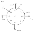
Fig. 1 is a drawing for explaining the basic construction of a first embodiment of the sound-source-search system of this invention:Fig. 2 and Fig. 3 are drawings for explaining the sound-source-search method by the sound-source-search system shown inFig. 1 : andFig. 4 is a drawing showing an example of the sound intensity distribution that is displayed on the display apparatus shown inFig. 1 . - The sound-source-search system shown in
Fig. 1 compr i ses abaffle 10,microphones 11,amp 20, A/D converter 30, arithmetic-processing apparatus 40,memory apparatus 50,display apparatus 60, andinput apparatus 70. It is possible for the arithmetic-processing apparatus 40,memory apparatus 50,display apparatus 60 andinput apparatus 70 to be constructed using an electronic device such as a notebook computer or desktop computer. - The
baffle 10 is spherical. Also, thebaffle 10 is installed at the top of a long member (not shown in the figure) such as a pole such that it is kept at a specified height from the ground plane. - A plurality of
microphones 11 is arranged on the surface of thebaffle 10. It is possible to use dynamic microphones or condenser microphones as themicrophones 11. - By placing the plurality of
microphones 11 on thespherical baffle 10 in this way, it becomes possible to pick up sound uniformly in all directions. The built-in main unit (not shown in the figure) such as the pre-amp (not shown in the figure) for themicrophones 11, and the microphone cables 11a that are connected to the main unit are installed inside thebaffle 10. - The radius of the
baffle 10 shown inFig. 1 is about 130 mm. Also, in this embodiment, the number ofmicrophones 11 placed on thebaffle 10 is 17. However, the number ofmicrophones 11 can be the minimum number necessary to correspond to the dimensions for searching for a sound source, and it is possible to use 2 microphones when searching for a sound source in one dimension, 3 microphones when searching for a sound source in two dimensions, and 4 microphones when searching for a sound source in 3 dimensions. In this embodiment, in order to improve precision and stability of the results of the sound-source search, 17 microphones are used. - By installing the built-in main unit (not shown in the figure) such as the pre-amp (not shown in the figure) for the
microphones 11, and the microphone cables 11a that are connected to the main unit on the inside of thespherical baffle 10 in this way, it is possible to suppress disturbances in the sound field around thebaffle 10, and thus it becomes possible to accurately pick up sound from the sound source. - Also, coordinates that indicate the position of each
microphone 11 on thebaffle 10 in three dimensions (x, y, z) are set, and they are used when the arithmetic-processing apparatus 40 performs arithmetic operations in the sound-source search. By doing so, it becomes possible to identify from which microphone 11 a picked up sound is coming from. - The
amp 20 is an amplifier that amplifies the analog signals that are electrical signals of the sounds obtained in all directions by each of themicrophones 11. The microphone cables 11a from each of themicrophones 11 are connected to theamp 20. Here, there is an insert port corresponding to the coordinates of each of themicrophones 11 described above, so when connecting the microphone cables 11a of themicrophones 11, the microphone cables 11a are inserted into and connected to the respective insert ports. The A/D converter 30 converts the analog signal that was amplified by theamp 20 to a digital signal. - The arithmetic-
processing apparatus 40 performs operations on the digital signal converted by the A/D converter 30, and searches for the sound source by processing sound information picked up by each of themicrophones 11 inclusively and as a whole. Here, the sound-source search is analysing the direction from which the sound arrives from the sound source, and estimating the intensity of the sound from the sound source. The sound-source search will be explained in detail later. - The
memory apparatus 50 stores the results of the arithmetic processing by the arithmetic-processing apparatus 40. As thememory apparatus 50, it is possible to use a magnetic-tape memory apparatus that uses magnetic tape as the recording medium, or an optical-disk memory apparatus that uses an optical disk as the recording medium. Thedisplay apparatus 60 displays the sound intensity distribution of the sound from the sound source based on the arithmetic processing results from the arithmetic-processing apparatus 40. Theinput apparatus 70 is used for entering the distance to the sound source or to sound sources generated at a plurality of sites on boundary surfaces such as walls in a room. It is possible to use a keyboard, touch panel or the like as the input apparatus. However, in the case where the purpose is to analyze the direction from which the sound comes, and calculate the acoustical contribution on the location of the baffle, and is not to estimate the intensity of the sound, it is possible to eliminate theinput apparatus 70. - Next, the method for performing the sound-source search will be explained.
- The search for a sound source can be performed in either a large space or a small space. In a large space, it is preferable that there be no obstacles between the
baffle 10 and the sound source being searched for: for example, in a location where a large number of people may congregate, thebaffle 10 should be set at a high location where it over looks the ent i re space: or in a location such as an airport, thebaffle 10 should be set in a location where no buildings or structures will become obstacles. On the other hand, in a small space such as indoors or inside a vehicle, thebaffle 10 should be placed in a location where it can overlook the entire space. - Also, as shown in
Fig. 2 , in the case of analyzing the direction from which the sound arrives from the sound source, analysis information for the sound field, which includes direct or diffracted sound around thebaffle 10, is entered into the arithmetic-processing apparatus 40. In this state, each of themicrophones 11 picks up the sound from the sound source. Here, when p i ck i ng up the sound from the sound source, sound is basically picked up by each of themicrophones 11 at the same time. Also, with a specified microphone as a reference, it is possible to pick up the sound in the order of the coord i nates mentioned above, or to p i ck up the sound w i th a plurality of microphones together, or to pick up the sound randomly at the same time as the reference microphone. However, the condition when not recording the sounds from all of the microphones at the same time is that the sound from the sound source must not change over time. - At this time, the sound from all directions obtained by way of each of the
microphones 11 enters theamp 20 as analog signals, and those signals are amplified by theamp 20 and output. The analog signals that are amplified by theamp 20 are converted to digital signals by the A/D converter 30 and then taken in by the arithmetic-processing apparatus 40. - In the arithmetic-
processing apparatus 40, analysis of the sound picked up by each of themicrophones 11 is performed by arithmetic processing. In this case, the amplitude characteristics and phase characteristics of each of the acoustic signals picked up by each of themicrophones 11 are found by arithmetic processing. Also, after these amplitude characteristics and phase characteristics have been found, analysis information for the sound field around thebaffle 10 described above is added, and arithmetic processing, which emphasizes the sound coming from a specified direction, is performed in all directions, making it possible to identify through arithmetic processing the direction from which the sound from the sound source comes. - Next, when est i mat i ng the intensity of the sound from the sound source, the distance d to the sound source shown in
Fig. 2 is entered into the arithmetic-processing apparatus 40 from theinput apparatus 70. At this time, the direction from which the sound from the sound source comes and the sound pressure are identified by the arithmetic-processing apparatus 40 as described above, so it is possible to estimate the intensity of the sound from the sound source through arithmetic processing from these ar i thmet i c process i ng results and the distance d to the sound source. When est i mat i ng the intensity of the sound from the sound source, by add i ng the distance d to the sound source to the conventional frequency domain beam forming method, it is possible to more accurately estimate the intensity of the sound from the sound source. - In this example, the case was explained in which, after analysis of the direction from which the sound from the sound from the sound source comes is finished, the distance d to the sound source used for estimating the intensity of the sound from the sound source is input to the arithmetic-
processing apparatus 40 from theinput apparatus 70, however, of course it is also possible to enter the distance d to the sound source into the arithmetic-processing apparatus 40 from theinput apparatus 70 before starting the sound-source search. - Also, in this example, as shown in
Fig. 2 , the case of analyzing the direction from which the sound from one sound source comes, and estimation of the intensity of the sound from one sound source was explained, however, as shown inFig. 3 , in the case of analyzing the direct ions from wh i ch sound comes from a plurality of sound sources generated at sites on boundary surfaces such as walls in a room, and estimating the intensity of the sound sources at each of these sites, it is possible to enter distances d1 to d4 to the sound sources a to d at these sites. - After analyzing the direction from which the sound from the sound source comes and estimating the intensity of the sound from the sound source by arithmetic processing by the arithmetic-
processing apparatus 40 as described above, the results of the arithmetic process are displayed in color by thedisplay apparatus 60 as the sound-intensity distribution.Fig. 4 shows an example of the sound-intensity distribution that is displayed by thedisplay apparatus 60. InFig. 4 , the size of the sound intensity is indicated, for example, by a to f (a > f > c > d > e > f). - In this first embodiment, a plurality of
microphones 11 are arranged on the surface of aspherical baffle 10 and sound is picked up from all directions in this way, and after the amplitude characteristics and phase characteristics of each of the acoustic signals picked up by the plurality ofmicrophones 11 are found through arithmetic processing by the arithmetic-processing apparatus 40, that signal information is combined with the analysis information for the sound field around the baffle, and arithmetic processing to emphasize the sound coming from a specific direction is performed for all directions, and together with identifying the direction from which sound from the sound source comes through arithmetic processing, the intensity of the sound from the sound source or from sound sources generated at a plurality of sites on boundaries is estimated from the arithmetic processing results and the distance entered from theinput apparatus 70, so regardless of whether or not the space is small, it is possible to identify the direction from which the sound from the sound source comes, and estimate the intensity of the sound from the sound source at the same time in all directions. - Also, in this first embodiment, set up work is very easy since it requires just setting a
baffle 10 having a plurality ofmicrophones 11 installed in place, and then connect i ng the microphone cables 11 a from themicrophones 11 to theamp 20. - I n this first embodiment, the case where the
baffle 10 was spherical was explained, however, the invention is not limited to this example, and it is possible for thebaffle 10 to be semi-spherical or polyhedral. Any one of the cases is possible as long as analysis information for the diffracted sound around thebaffle 10 can be obtained in some form. In this way, even when thebaffle 10 is semi-spherical or polyhedral, themicrophones 11 are built-in the baffle, so it is possible to suppress distortion in the sound field around thebaffle 10, and thus it is possible to perform the sound-source search accurately. - Also, the material used for the
baffle 10 can be any material, such as stainless steel, aluminum alloy, copper alloy or the like, that retains sufficient strength after a plurality ofmicrophones 11 has been built in. It is possible to perform polishing or rough i ng of the surface of thebaffle 10, and it is also possible to attach sound absorption material. In any case, as long as it is possible to obtain analysis information for diffracted sound around thebaffle 10 due to the shape or material of thebaffle 10, it is possible to accurately analyze the direction from which the sound from the sound source comes, and estimate the intensity of the sound source even though the shape and material of thebaffle 10 may differ. -
Fig. 5 is a drawing showing a second embodiment in which one or more sound source elements for measuring distance are added to thebaffle 10 shown inFig. 1 . In the drawing explained below, the same reference numbers are used for parts that are in common with those ofFig. 1 to Fig. 3 , and any redundant explanation will be omitted. - In this second embodiment shown in
Fig. 5 , there are one or more sound-source elements 12 for measuring distance placed on the surface of thebaffle 10 and they generate sound waves. It is possible to use directive or non-directive acoustical speakers or ultrasonic speakers as the sound-source elements 12 for measuring distance. - With this kind of construction, sound waves are generated from the sound-
source elements 12 for measuring distance, and the reflected waves of those waves are picked up by each of themicrophones 11, and then after the amplitude characteristics and phase characteristics of each of the reflected waves picked up by each of themicrophones 11 have been found through arithmetic processing by the arithmetic-processing apparatus 40, that signal information is combined with the analysis information for the sound field around thebaffle 10, and by adding the time from when the sound waves are generated until the reflected waves are picked up together with performing arithmetic processing to emphasize the sound coming from a specified direction in all directions, and identifying the direction from which sound from the boundary surfaces comes from through arithmetic processing, it is possible to automatically measure the distance to the sound source or to sound sources generated at a plurality of sites on the boundary surfaces. - By automatically measuring the distance to the sound source or one or more sound sources generated at a plurality sites on boundary surfaces in this way, not only is it possible to more accurately analyze the direction from wh i ch the sound from the sound source comes and est i mate the intensity of the sound from the sound source, but it is also possible to gain a better understanding beforehand of buildings, obstacles, mountains near the observed area, or the shape and location inside a vehicle or room.
- Moreover, by analyzing the reflected sound characteristics such as the direction from which a test sound generated by a sound-
source element 12 for measur i ng distance and its reflected sound comes for every direction, intensity, and phase, it becomes possible to also investigate the acoust i cs such as the reverberation time at that place and the echo time pattern. - It is also possible to use a test wave having a specific frequency as the sound wave from the sound-
source element 12 for measur i ng distance, and it is also possible to use random noise, pseudo random noise, an M-sequence signal, a frequency-sweep signal, or the like to perform arithmetic processing and automatically measure the distance to sound sources at one or more sites. After measuring the distance to the sound source or sound sources generated at a plurality of sites on the boundary surfaces in this way, it is possible to more accurately analyze the direction from which sound from the sound source comes, and estimate the intensity of the sound from the sound source. -
Fig. 6 is a drawing showing a third embodiment in which one or more light-receiving elements are added to thebaffle 10 shown inFig. 5 . - I n this third embodiment shown in
Fig. 6 , one or more light-receivingelements 13 are arranged on the surface of thebaffle 10. It is possible to use a camera such as a CCD camera compr i s i ng a CCD (Charge Coupled Device) and lens, a laser-receiving element, infrared-ray-receiving element or the like as the light-receivingelement 13. - In the case of a camera as the light-receiving
element 13, it is preferred that each light-receivingelement 13 be placed such that its imaging range overlaps that of the adjacent light-receiving elements. In other words, as shown inFig. 7 , by having the light-receivingelement 13 take an image of the image range X and Y, and the other adjacent light-receivingelement 13 take an image of the image range Y and Z, the image ranges Y overlap. - With this kind of construction, since a plurality of light-receiving
elements 13 are arranged on the surface of the baff le 10 such that the image ranges overlap, it is possible to automatically take in an image of around the sound source or sound sources generated at a plurality of sites on the boundary surfaces that correspond to the direction from which a specific sound comes, and to display that obtained image in color by thedisplay apparatus 60.Fig. 8 shows an example of the image displayed by thedisplay apparatus 60. - Moreover, it is possible to combine and display the image of the sound-intensity distribution shown in
Fig. 4 with the image shown inFig. 8 . In that case, by selecting the area indicated by the dotted line in the image shown inFig. 9A corresponds to the image shown inFig. 4 , the image corresponding to that selected area is obtained as shown inFig. 9B , and the sound-intensity distribution of the area selected inFig. 9A is comb i ned with the image shown inFig. 9B as shown inFig. 9C and displayed. - By automatically taking images with the light-receiving
elements 13 in this way, in addition to the effects described above, it is possible to display the direction from which the sound comes and/or the sound-intensity distribution, and thus it becomes easy to visually grasp those distributions. - When a laser-receiving element, infrared-ray-receiving element or the like is used as the light-receiving
element 13, they are effectively used in a fourth embodiment described below. -
Fig. 10 is a drawing showing a fourth embodiment in which a plurality of light sources is added to thebaffle 10 shown inFig. 6 . - In this fourth embodiment shown in
Fig. 10 , a plurality oflight sources 14 is arranged on the surface of thebaffle 10. It is possible to use CCD-camera lighting, a laser pointer, a laser range finder, strobe or the like as thelight source 14. - When a light source having sharp directivity such as a laser pointer is used in this kind of construction, it is possible to accurately set the installation location of the baffle even when installing the baffle in difficult locations.
- When a range finder such as a laser range finder is used in this kind of construction, light is emitted from the
light source 14, and the reflected light of that light is received by the light-receivingunit 13, making it possible to automatically measure the distance to the boundary surface, which can be the baffle or sound source. - Also, by using the light generated by the
light source 14, it is possible to light up the area of the sound source or sound sources generated at a plurality of sites on the boundary surfaces, so even in an area with dim lighting, it is possible to take good images with the light-receivingelements 13. - When a strobe light source is used as the light from the
light source 14, by sh i n i ng a light onto a rotat i ng body and keep i ng the flashing per i od of the light from thelight source 14 constant, then by measur i ng the period when the rotat i ng flashing per i od and rotat i on cycle match and the rotat i ng body appears to be still, it is possible to remotely measure the speed of the rotat i ng body. Also, similarly, when the flashing per i od of the light is constant and it is shown onto a vibrating surface, using the theory of the stroboscope, it becomes possible for the light-receivingelements 13 to observe the vibration state of a boundary surface, which is the sound source. -
Fig. 11 is a drawing explaining a fifth embodiment in which the light-receivingelements 13 shown inFig. 6 automatically measure the distance to the sound source or sound sources generated at a plurality of sites on the boundary surfaces. - In this fifth embodiment shown in
Fig. 11 , similar to as was explained above, after images have been automatically taken by the light-receivingelements 13, the images where the imaging range of adjacent light-receivingelements 13 overlap are processed, and the distance to the sound source or sound sources generated at a plurality of sites on the boundary surfaces is automatically measured. By having the light-receivingelements 13 automatically take images in this way and then having the arithmetic-processing apparatus 40 process the image of the overlapping area, and automatically measure the distance to the sound source, then similar to as was described above, it becomes possible to accurately estimate the intensity of the sound from the sound source or sound sources generated at a plurality of sites on the boundary surfaces. -
Fig. 12 is a drawing showing a sixth embodiment in which, as an example of having a plurality of thebaffles 10 shown inFig. 6 , twobaffles 10 are used. - In this sixth embodiment shown in
Fig. 12 , by having twobaffles 10, through arithmetic processing by the arithmetic-processing apparatus 40, it is possible to obta i n the distance from onebaffle 10 to the sound source and/or the d i rect i on from wh i ch the sound comes, the distance from theother baffle 10 to the sound source and/or d i rect i on from wh i ch the sound comes, and the positional relationship between the pair ofbaffles 10. Also, based on that information, the distance to the sound source is even more accurately measured accord i ng to the theory of tr i angu lation, and of course, it is possible to more accurately measure the intensity of the sound from the sound source ; and compared with the case of us i ng on I y one baffle, when the number of microphones used is increased, the range of received sound is expanded, and it becomes possible to greatly improve the precision of the sound-source search. -
Fig. 13 is a drawing showing a seventh embodiment in which a plurality of satellite microphones is located on thebaffle 10 shown inFig. 1 . - In this seventh embodiment shown in
Fig. 13 , a plurality ofsatellite microphones 11A is arranged on thebaffle 10. - By arranging a plurality of
satellite microphones 11A on thebaffle 10 in this way, in addition to the built-in microphones on thebaffle 10, the arithmetic-processing apparatus 40 is able to use acoustic information from the satellite microphones in the sound-source search. As in the case of the microphones arranged on thebaffle 10, it is preferred that the acoustic information from thesatellite microphones 11 A be used in a form in which analysis information about the diffracted sound around thebaffle 10 has been added. Thesatellite microphones 11A are located further outside than thebaffle 10, and have the effect of virtually increasing the size of thebaffle 10 without having to change the size of thebaffle 10. Since the number of microphones that can be used in the sound-source search is increased, it becomes possible to greatly increase the precision of the sound-source search. - In this seventh embodiment, the case of placing a plurality of
satellite microphones 11 A around thebaffle 10 shown inFig. 1 was explained, however, the invention is not limited to this example, and of course it is also possible to place a plurality ofsatellites microphones 11A around thebaffle 10 shown inFig. 5 ,Fig. 6 ,Fig. 10 orFig. 12 . Naturally, it is also possible to replace the microphones on the baffle completely with satellite microphones. - With the sound-source search system of this invention as described above, one or more microphones are arranged on and/or near the surface of a spherical, semi-spherical or polyhedral baffle to p i ck up sound from all directions, and after an arithmetic-processing apparatus identifies the direction from wh i ch sound comes through ar i thmet i c process i ng that focuses on the amplitude characteristics and phase characteristics of the acoustic signals picked up by the plurality of microphones, the intensity of the sound from the sound source or sound sources generated at a plurality of sites on boundary surfaces is estimated from the arithmetic processing results and distances entered from an input apparatus or measured by sound-source, light-source or image processing, so regardless of whether or not the space is small, it is possible to identify the direction from which sound from the sound source comes, and to estimate the intensity of the sound source in all directions at the same time.
Claims (8)
- A sound-source search system comprising:a spherical, semi-spherical or polyhedral baffle (10) ;a plurality of microphones (11) that are arranged on the surface of said baffle (10) for picking up sound in all directions;an amplifier (20) that amplifies analog signals, which are electrical signals for the sounds in all directions that were picked up by said plurality of microphones (11);an A/D converter (30) that converts the analog signals that were amplified by said amplifier (20) to digital signals;an arithmetic-processing apparatus (40) adapted to perform arithmetic processing on the digital signals that were converted by said A/D converter (30), and adapted to analyze each direction from which the sound from a sound source comes, and/or adapted to estimate each intensity of the sound from a sound source;
a memory apparatus (50) for storing the results of the arithmetic processing by said arithmetic-processing apparatus (40);
a display apparatus (60) that displays the intensity distribution of the sound from a sound source based on the results of the arithmetic processing by said arithmetic-processing apparatus (40); and
an input apparatus (70) for entering the distance from the baffle (10) to a sound source, or the distances from the baffle (10) to sound sources generated at a plurality of sites on boundary surfaces; and wherein
said arithmetic-processing apparatus (40) is adapted to find by arithmetic processing the amplitude characteristics and phase characteristics of each of the acoustic signals picked up by said plurality of microphones as signal information, and is adapted to combine that signal information with analysis information including direct or diffracted sound of the sound field around said baffle (10), and is adapted to perform arithmetic processing to emphasize the sound coming from a specific direction for all directions, and to identify the direction from which the sound comes, and to estimate the intensity of the sound from a sound source or sound sources generated at one or more of sites on boundary surfaces based on the arithmetic-processing results and distance or distances input from said input apparatus (70). - A sound-source search system comprising:a spherical, semi-spherical or polyhedral baffle (10);a plurality of microphones (11) that are arranged on the surface of said baffle (10) for picking up sound in all directions;an amplifier (20) that amplifies analog signals, which are electrical signals for the sounds in all directions that were picked up by said plurality of microphones (11);an A/D converter (30) that converts the analog signals that were amplified by said amplifier (20) to digital signals;
an arithmetic-processing apparatus (40) adapted to perform arithmetic processing on the digital signals that were converted by said A/D converter (30), and adapted to find the amplitude characteristics and phase characteristics of each of the acoustic signals picked up by that plurality of microphones (11) as signal information, adapted to combine that signal information with analysis information of the sound field around said baffle (10) and adapted to perform arithmetic processing to emphasize the sound coming from a specific direction for all directions, and adapted to identify the direction from which the sound comes and to estimate the intensity of the sound from a sound source or sound sources generated at one or more sites on boundary surfaces by using the value of the distance or the distances between the baffle (10) and a sound source or sound sources as information;a memory apparatus (50) for storing the results of the arithmetic processing by said arithmetic-processing apparatus (40) ;
a display apparatus (60) that displays the intensity distribution of the sound from a sound source based on the results of the arithmetic processing by said arithmetic-processing apparatus (40); andone or more directive or non-directive sound-source elements (12) that generate sound waves as a test sound that is not correlated to the sound of the one or more external sound sources and that are arranged on the surface of said baffle (10); wherein
said arithmetic-processing apparatus is adapted by arithmetic processing to find the amplitude characteristics and phase characteristics of each of the reflected sounds that are picked up by said plurality of microphones (11) after combining that signal information with analysis information for the sound field around said baffle (10), and adapted to perform arithmetic processing to emphasize the sound coming from a specific direction for all directions, and to identify the direction from which the reflected sound comes, and adapted to automatically measure the distance or the distances from the baffle to a sound source or sound sources generated at one or more sites on boundary surfaces by using the time difference from when the test sound was generated to when the reflected sound was picked up. - The sound-source-search system of claim 1 or claim 2 further comprising one or more light-receiving elements (13) that are arranged on the surface of said baffle (10) such that the imaging ranges overlap; and wherein
said arithmetic-processing apparatus (40) is adapted to take in the image from said one or more light-receiving elements (13) that corresponds to the identified direction from which said specific sound comes, and is adapted to combine and display the image of the arrival direction and/or intensity of the sound distribution found through said arithmetic processing with that image or the result of image processing based on that image. - The sound-source-search system of claim 3 further comprising one or more light sources (14) that are arranged on the surface of said baffle (10); and wherein
said arithmetic-processing apparatus (40) is adapted to automatically measure the distance from said baffle (10) to sound sources generated at a plurality of sites on boundary surfaces by using the time from when light was generated until the reflected light was taken in; and is adapted to use that value as information for estimating the intensity of the sound from the sound source or sound sources generated at one or more sites on boundary surfaces. - The sound-source search system of claim 3 or claim 4
wherein
said arithmetic-processing apparatus (40) is adapted to perform an image processing on the area of the imaging range of said light-receiving elements (13) that overlap, is adapted to automatically measure the distance to the sound source or sound sources generated at one or more sites on boundary surfaces. - The sound-source-search system of any one of the claims 1 to 5 comprising a plurality of said baffles (10) ; and wherein
said arithmetic-processing apparatus (40) is adapted to find: the distance from one of the baffles (10) to the sound source or sound sources generated at one or more sites on boundary surfaces and/or the direction from which the sound comes; the distance from one of an other of said baffles (10) to the sound source or sound sources generated at one or more sites on boundary surfaces and/or the direction from which the sound comes; and the positional relationship between said baffles (10); and is adapted to use after that,
the theory of triangulation based on this information to find the distance to the sound source or sound sources generated at one or more sites on boundary surfaces. - The sound-source-search system of any one of the claims 1 to 6 further comprising one or more satellite microphones (11A) that are arranged at locations separated from the surface of said baffle (10); and wherein
said arithmetic-processing apparatus (40) is adapted to use the sound picked up by said plurality of satellite microphones (11A) to find the direction from which the sound comes and/or intensity of the sound from the sound source. - The sound-source-search apparatus of any one of the claims 1 to 7 wherein said baffle (10) is installed at the top of a long member such that it is held at a specified height above the ground.
Applications Claiming Priority (3)
| Application Number | Priority Date | Filing Date | Title |
|---|---|---|---|
| JP2002293025 | 2002-08-30 | ||
| JP2002093025 | 2002-08-30 | ||
| PCT/JP2003/010851 WO2004021031A1 (en) | 2002-08-30 | 2003-08-27 | Sound source search system |
Publications (3)
| Publication Number | Publication Date |
|---|---|
| EP1544635A1 EP1544635A1 (en) | 2005-06-22 |
| EP1544635A4 EP1544635A4 (en) | 2010-10-13 |
| EP1544635B1 true EP1544635B1 (en) | 2012-01-18 |
Family
ID=31973467
Family Applications (1)
| Application Number | Title | Priority Date | Filing Date |
|---|---|---|---|
| EP03791338A Expired - Lifetime EP1544635B1 (en) | 2002-08-30 | 2003-08-27 | Sound source search system |
Country Status (8)
| Country | Link |
|---|---|
| US (1) | US7379553B2 (en) |
| EP (1) | EP1544635B1 (en) |
| JP (1) | JP4368798B2 (en) |
| KR (1) | KR101010099B1 (en) |
| AT (1) | ATE542149T1 (en) |
| AU (1) | AU2003261759A1 (en) |
| CA (1) | CA2496785C (en) |
| WO (1) | WO2004021031A1 (en) |
Families Citing this family (54)
| Publication number | Priority date | Publication date | Assignee | Title |
|---|---|---|---|---|
| FR2858403B1 (en) * | 2003-07-31 | 2005-11-18 | Remy Henri Denis Bruno | SYSTEM AND METHOD FOR DETERMINING REPRESENTATION OF AN ACOUSTIC FIELD |
| JP2006245725A (en) * | 2005-03-01 | 2006-09-14 | Yamaha Corp | Microphone system |
| JP4804095B2 (en) * | 2005-10-07 | 2011-10-26 | パナソニック株式会社 | Microphone device |
| JP2007121045A (en) * | 2005-10-26 | 2007-05-17 | Matsushita Electric Works Ltd | Ultrasonic object detector |
| EP1983799B1 (en) | 2007-04-17 | 2010-07-07 | Harman Becker Automotive Systems GmbH | Acoustic localization of a speaker |
| JP5094377B2 (en) * | 2007-12-28 | 2012-12-12 | 富士通コンポーネント株式会社 | KVM switch and remote system |
| EP2233897A1 (en) * | 2008-01-18 | 2010-09-29 | Nittobo Acoustic Engineering Co., Ltd. | Sound source identifying and measuring apparatus, system and method |
| JP5686358B2 (en) * | 2008-03-07 | 2015-03-18 | 学校法人日本大学 | Sound source distance measuring device and acoustic information separating device using the same |
| JP2010011433A (en) * | 2008-05-30 | 2010-01-14 | Nittobo Acoustic Engineering Co Ltd | Sound source separation and display method, and system thereof |
| US8314829B2 (en) * | 2008-08-12 | 2012-11-20 | Microsoft Corporation | Satellite microphones for improved speaker detection and zoom |
| KR101064976B1 (en) * | 2009-04-06 | 2011-09-15 | 한국과학기술원 | System for identifying the acoustic source position in real time and robot which reacts to or communicates with the acoustic source properly and has the system |
| JP5350914B2 (en) * | 2009-06-30 | 2013-11-27 | 西松建設株式会社 | Noise monitoring system and noise monitoring method |
| JP5452158B2 (en) * | 2009-10-07 | 2014-03-26 | 株式会社日立製作所 | Acoustic monitoring system and sound collection system |
| US8207453B2 (en) | 2009-12-17 | 2012-06-26 | Intel Corporation | Glass core substrate for integrated circuit devices and methods of making the same |
| US9420707B2 (en) | 2009-12-17 | 2016-08-16 | Intel Corporation | Substrate for integrated circuit devices including multi-layer glass core and methods of making the same |
| JP5390447B2 (en) * | 2010-03-26 | 2014-01-15 | 株式会社高速道路総合技術研究所 | Method for estimating noise countermeasure effect |
| EP2375779A3 (en) * | 2010-03-31 | 2012-01-18 | Fraunhofer-Gesellschaft zur Förderung der Angewandten Forschung e.V. | Apparatus and method for measuring a plurality of loudspeakers and microphone array |
| US9496841B2 (en) * | 2010-10-21 | 2016-11-15 | Nokia Technologies Oy | Recording level adjustment using a distance to a sound source |
| JP2012133250A (en) | 2010-12-24 | 2012-07-12 | Sony Corp | Sound information display apparatus, method and program |
| JP5016724B1 (en) * | 2011-03-18 | 2012-09-05 | リオン株式会社 | Noise observation apparatus and noise observation method |
| US9973848B2 (en) | 2011-06-21 | 2018-05-15 | Amazon Technologies, Inc. | Signal-enhancing beamforming in an augmented reality environment |
| JP5642027B2 (en) * | 2011-07-06 | 2014-12-17 | 株式会社日立パワーソリューションズ | Abnormal sound diagnosis apparatus and abnormal sound diagnosis method |
| WO2013015461A1 (en) * | 2011-07-22 | 2013-01-31 | 엘지전자 주식회사 | Device for detecting the direction of a sound source, and surveillance camera including same |
| JP5721840B2 (en) * | 2011-12-01 | 2015-05-20 | 日東紡音響エンジニアリング株式会社 | Acoustic performance calculation apparatus, acoustic performance calculation method, and acoustic performance calculation program |
| KR101282673B1 (en) | 2011-12-09 | 2013-07-05 | 현대자동차주식회사 | Method for Sound Source Localization |
| JP6031761B2 (en) * | 2011-12-28 | 2016-11-24 | 富士ゼロックス株式会社 | Speech analysis apparatus and speech analysis system |
| WO2013133827A1 (en) | 2012-03-07 | 2013-09-12 | Intel Corporation | Glass clad microelectronic substrate |
| CN102955148A (en) * | 2012-11-04 | 2013-03-06 | 李良杰 | Spherical infrared sensor array direction finder |
| CN102968128A (en) * | 2012-11-13 | 2013-03-13 | 李良杰 | Device for obtaining sun directions |
| US9042563B1 (en) * | 2014-04-11 | 2015-05-26 | John Beaty | System and method to localize sound and provide real-time world coordinates with communication |
| US9769552B2 (en) | 2014-08-19 | 2017-09-19 | Apple Inc. | Method and apparatus for estimating talker distance |
| US10909384B2 (en) * | 2015-07-14 | 2021-02-02 | Panasonic Intellectual Property Management Co., Ltd. | Monitoring system and monitoring method |
| CN105116406B (en) * | 2015-09-30 | 2018-11-30 | 长沙开山斧智能科技有限公司 | A kind of compound rangefinder and its distance measuring method |
| US11067661B2 (en) * | 2015-11-17 | 2021-07-20 | Sony Corporation | Information processing device and information processing method |
| JP2017102085A (en) * | 2015-12-04 | 2017-06-08 | キヤノン株式会社 | Information processing apparatus, information processing method, and program |
| CN107290711A (en) * | 2016-03-30 | 2017-10-24 | 芋头科技(杭州)有限公司 | A kind of voice is sought to system and method |
| CN107402571A (en) | 2016-05-20 | 2017-11-28 | 富泰华工业(深圳)有限公司 | Intensity of sound positioning guidance system and method |
| US10656266B2 (en) | 2016-09-13 | 2020-05-19 | Walmart Apollo, Llc | System and methods for estimating storage capacity and identifying actions based on sound detection |
| US10070238B2 (en) | 2016-09-13 | 2018-09-04 | Walmart Apollo, Llc | System and methods for identifying an action of a forklift based on sound detection |
| CN106954126B (en) * | 2017-03-31 | 2020-01-10 | 深圳壹秘科技有限公司 | Audio information processing method and conference terminal thereof |
| US11209306B2 (en) | 2017-11-02 | 2021-12-28 | Fluke Corporation | Portable acoustic imaging tool with scanning and analysis capability |
| CN109830998A (en) * | 2017-11-23 | 2019-05-31 | 富泰华工业(深圳)有限公司 | Recharging device |
| JP7072186B2 (en) * | 2018-02-08 | 2022-05-20 | 株式会社オーディオテクニカ | Microphone device and case for microphone device |
| CN108389571A (en) * | 2018-04-11 | 2018-08-10 | 李良杰 | Active noise reducing device |
| US10951859B2 (en) | 2018-05-30 | 2021-03-16 | Microsoft Technology Licensing, Llc | Videoconferencing device and method |
| WO2020023633A1 (en) * | 2018-07-24 | 2020-01-30 | Fluke Corporation | Systems and methods for tagging and linking acoustic images |
| JP2020036214A (en) | 2018-08-30 | 2020-03-05 | Tdk株式会社 | MEMS microphone |
| JP2020036215A (en) | 2018-08-30 | 2020-03-05 | Tdk株式会社 | MEMS microphone |
| US11795032B2 (en) | 2018-11-13 | 2023-10-24 | Otis Elevator Company | Monitoring system |
| JP7245034B2 (en) * | 2018-11-27 | 2023-03-23 | キヤノン株式会社 | SIGNAL PROCESSING DEVICE, SIGNAL PROCESSING METHOD, AND PROGRAM |
| KR102207070B1 (en) * | 2019-07-16 | 2021-01-22 | 동명대학교산학협력단 | A Simple Estimation Method for Estimating Sound Source Orientation in Reverberant Water Tank |
| WO2021064917A1 (en) * | 2019-10-02 | 2021-04-08 | 日本電信電話株式会社 | Relationship determination device, method, and program |
| US11418873B2 (en) | 2020-11-03 | 2022-08-16 | Edward J. Simon | Surveillance microphone |
| CN115240678B (en) * | 2022-09-21 | 2022-12-09 | 深圳市英特飞电子有限公司 | Intelligent voice recognition device |
Family Cites Families (15)
| Publication number | Priority date | Publication date | Assignee | Title |
|---|---|---|---|---|
| US4496022A (en) * | 1983-02-22 | 1985-01-29 | Prohs John R | System for interrelating sound transducers or sound sources and their environment |
| JPH0726887B2 (en) * | 1986-05-31 | 1995-03-29 | 株式会社堀場製作所 | Condenser Microphone type detector diaphragm |
| JPH0472525A (en) | 1990-07-13 | 1992-03-06 | Nippon Telegr & Teleph Corp <Ntt> | Sound source direction distinguishing sensor |
| JPH06113387A (en) | 1992-09-25 | 1994-04-22 | Railway Technical Res Inst | Sound image visualizing device for sound source observation |
| JPH0737908B2 (en) * | 1993-03-02 | 1995-04-26 | 日本電気株式会社 | Mobile noise monitoring system |
| US5717656A (en) * | 1996-08-20 | 1998-02-10 | Ybm Technologies, Inc. | Method and apparatus for detecting and locating a concealed listening device |
| JPH10332807A (en) * | 1997-06-05 | 1998-12-18 | Fujitsu Ltd | Sound source direction detector |
| JPH1164089A (en) | 1997-08-18 | 1999-03-05 | Toshiba Corp | Wave motion diagnostic equipment |
| JP4815661B2 (en) * | 2000-08-24 | 2011-11-16 | ソニー株式会社 | Signal processing apparatus and signal processing method |
| JP4868671B2 (en) | 2001-09-27 | 2012-02-01 | 中部電力株式会社 | Sound source exploration system |
| DE60134335D1 (en) | 2000-10-02 | 2008-07-17 | Chubu Electric Power | SOUND SYSTEM FOR SOUND SOURCES |
| JP4722347B2 (en) * | 2000-10-02 | 2011-07-13 | 中部電力株式会社 | Sound source exploration system |
| US7039198B2 (en) * | 2000-11-10 | 2006-05-02 | Quindi | Acoustic source localization system and method |
| US6978030B2 (en) * | 2001-09-13 | 2005-12-20 | Reich Ronald S | Light emitting loudspeaker cover |
| US20030147539A1 (en) * | 2002-01-11 | 2003-08-07 | Mh Acoustics, Llc, A Delaware Corporation | Audio system based on at least second-order eigenbeams |
-
2003
- 2003-08-27 US US10/525,908 patent/US7379553B2/en not_active Expired - Lifetime
- 2003-08-27 AT AT03791338T patent/ATE542149T1/en active
- 2003-08-27 CA CA2496785A patent/CA2496785C/en not_active Expired - Fee Related
- 2003-08-27 KR KR1020057003061A patent/KR101010099B1/en active IP Right Grant
- 2003-08-27 WO PCT/JP2003/010851 patent/WO2004021031A1/en active Application Filing
- 2003-08-27 EP EP03791338A patent/EP1544635B1/en not_active Expired - Lifetime
- 2003-08-27 AU AU2003261759A patent/AU2003261759A1/en not_active Abandoned
- 2003-08-27 JP JP2004532729A patent/JP4368798B2/en not_active Expired - Lifetime
Also Published As
| Publication number | Publication date |
|---|---|
| ATE542149T1 (en) | 2012-02-15 |
| JPWO2004021031A1 (en) | 2005-12-22 |
| KR101010099B1 (en) | 2011-01-24 |
| US20050246167A1 (en) | 2005-11-03 |
| EP1544635A4 (en) | 2010-10-13 |
| AU2003261759A1 (en) | 2004-03-19 |
| EP1544635A1 (en) | 2005-06-22 |
| JP4368798B2 (en) | 2009-11-18 |
| CA2496785C (en) | 2011-11-22 |
| US7379553B2 (en) | 2008-05-27 |
| CA2496785A1 (en) | 2004-03-11 |
| WO2004021031A1 (en) | 2004-03-11 |
| KR20050058467A (en) | 2005-06-16 |
Similar Documents
| Publication | Publication Date | Title |
|---|---|---|
| EP1544635B1 (en) | Sound source search system | |
| CN109863375B (en) | Acoustic imaging device and method for measuring, processing and visualizing acoustic signals | |
| JP5004276B2 (en) | Sound source direction determination apparatus and method | |
| US11307285B2 (en) | Apparatus, system and method for spatially locating sound sources | |
| JP2011015050A (en) | Array for beam forming, and sound source exploration/measurement system using the same | |
| Ginn et al. | Noise source identification techniques: simple to advanced applications | |
| US9557400B2 (en) | 3D soundscaping | |
| Atmoko et al. | Accurate sound source localization in a reverberant environment using multiple acoustic sensors | |
| JP2004085201A (en) | Vibration source probing system | |
| Prezelj et al. | A novel approach to localization of environmental noise sources: Sub-windowing for time domain beamforming | |
| JP4248458B2 (en) | Sound pressure measurement method | |
| Legg et al. | A combined microphone and camera calibration technique with application to acoustic imaging | |
| KR20090128221A (en) | Method for sound source localization and system thereof | |
| JP2005181088A (en) | Motion-capturing system and motion-capturing method | |
| KR20060124443A (en) | Sound source localization method using head related transfer function database | |
| Shimoyama et al. | Acoustic source localization using phase difference spectrum images | |
| KR102180229B1 (en) | Apparatus for Estimating Sound Source Localization and Robot Having The Same | |
| Son et al. | Design and Implementation of an Indoor Ambient Noise Monitoring System with Localization | |
| Yadav et al. | Study of MVDR Beamformer for a single Acoustic Vector Sensor | |
| US20070025563A1 (en) | Snapshot of noise and acoustic propagation | |
| WO2024028784A1 (en) | Diagnosis system for vehicle components | |
| Sohn et al. | Development of Noise Source Detection System using Array Microphone in Power Plant Equipment | |
| Parr et al. | Development of a Hand-held 3D Scanning Acoustic Camera | |
| Wu et al. | Locating Multiple Incoherent Sound Sources in 3D Space in Real Time | |
| Comesana et al. | Assessing vehicle exterior noise using a virtual phased array (VPA) |
Legal Events
| Date | Code | Title | Description |
|---|---|---|---|
| PUAI | Public reference made under article 153(3) epc to a published international application that has entered the european phase |
Free format text: ORIGINAL CODE: 0009012 |
|
| 17P | Request for examination filed |
Effective date: 20050210 |
|
| AK | Designated contracting states |
Kind code of ref document: A1 Designated state(s): AT BE BG CH CY CZ DE DK EE ES FI FR GB GR HU IE IT LI LU MC NL PT RO SE SI SK TR |
|
| AX | Request for extension of the european patent |
Extension state: AL LT LV MK |
|
| DAX | Request for extension of the european patent (deleted) | ||
| A4 | Supplementary search report drawn up and despatched |
Effective date: 20100909 |
|
| 17Q | First examination report despatched |
Effective date: 20101202 |
|
| RIC1 | Information provided on ipc code assigned before grant |
Ipc: H04R 3/00 20060101ALI20110617BHEP Ipc: G01S 3/80 20060101AFI20110617BHEP |
|
| GRAP | Despatch of communication of intention to grant a patent |
Free format text: ORIGINAL CODE: EPIDOSNIGR1 |
|
| GRAS | Grant fee paid |
Free format text: ORIGINAL CODE: EPIDOSNIGR3 |
|
| GRAA | (expected) grant |
Free format text: ORIGINAL CODE: 0009210 |
|
| AK | Designated contracting states |
Kind code of ref document: B1 Designated state(s): AT BE BG CH CY CZ DE DK EE ES FI FR GB GR HU IE IT LI LU MC NL PT RO SE SI SK TR |
|
| REG | Reference to a national code |
Ref country code: GB Ref legal event code: FG4D |
|
| REG | Reference to a national code |
Ref country code: DE Ref legal event code: R081 Ref document number: 60339784 Country of ref document: DE Owner name: NIHON ONKYO ENGINEERING CO., LTD., JP Free format text: FORMER OWNER: NITTOBO ACOUSTIC ENGINEERING CO. LTD., TOKIO/TOKYO, JP |
|
| REG | Reference to a national code |
Ref country code: CH Ref legal event code: EP |
|
| REG | Reference to a national code |
Ref country code: IE Ref legal event code: FG4D Ref country code: AT Ref legal event code: REF Ref document number: 542149 Country of ref document: AT Kind code of ref document: T Effective date: 20120215 |
|
| REG | Reference to a national code |
Ref country code: DE Ref legal event code: R096 Ref document number: 60339784 Country of ref document: DE Effective date: 20120315 |
|
| REG | Reference to a national code |
Ref country code: NL Ref legal event code: VDEP Effective date: 20120118 |
|
| PG25 | Lapsed in a contracting state [announced via postgrant information from national office to epo] |
Ref country code: NL Free format text: LAPSE BECAUSE OF FAILURE TO SUBMIT A TRANSLATION OF THE DESCRIPTION OR TO PAY THE FEE WITHIN THE PRESCRIBED TIME-LIMIT Effective date: 20120118 Ref country code: BE Free format text: LAPSE BECAUSE OF FAILURE TO SUBMIT A TRANSLATION OF THE DESCRIPTION OR TO PAY THE FEE WITHIN THE PRESCRIBED TIME-LIMIT Effective date: 20120118 Ref country code: BG Free format text: LAPSE BECAUSE OF FAILURE TO SUBMIT A TRANSLATION OF THE DESCRIPTION OR TO PAY THE FEE WITHIN THE PRESCRIBED TIME-LIMIT Effective date: 20120418 |
|
| PG25 | Lapsed in a contracting state [announced via postgrant information from national office to epo] |
Ref country code: FI Free format text: LAPSE BECAUSE OF FAILURE TO SUBMIT A TRANSLATION OF THE DESCRIPTION OR TO PAY THE FEE WITHIN THE PRESCRIBED TIME-LIMIT Effective date: 20120118 Ref country code: GR Free format text: LAPSE BECAUSE OF FAILURE TO SUBMIT A TRANSLATION OF THE DESCRIPTION OR TO PAY THE FEE WITHIN THE PRESCRIBED TIME-LIMIT Effective date: 20120419 Ref country code: PT Free format text: LAPSE BECAUSE OF FAILURE TO SUBMIT A TRANSLATION OF THE DESCRIPTION OR TO PAY THE FEE WITHIN THE PRESCRIBED TIME-LIMIT Effective date: 20120518 |
|
| REG | Reference to a national code |
Ref country code: AT Ref legal event code: MK05 Ref document number: 542149 Country of ref document: AT Kind code of ref document: T Effective date: 20120118 |
|
| PG25 | Lapsed in a contracting state [announced via postgrant information from national office to epo] |
Ref country code: CY Free format text: LAPSE BECAUSE OF FAILURE TO SUBMIT A TRANSLATION OF THE DESCRIPTION OR TO PAY THE FEE WITHIN THE PRESCRIBED TIME-LIMIT Effective date: 20120118 |
|
| PG25 | Lapsed in a contracting state [announced via postgrant information from national office to epo] |
Ref country code: SE Free format text: LAPSE BECAUSE OF FAILURE TO SUBMIT A TRANSLATION OF THE DESCRIPTION OR TO PAY THE FEE WITHIN THE PRESCRIBED TIME-LIMIT Effective date: 20120118 Ref country code: RO Free format text: LAPSE BECAUSE OF FAILURE TO SUBMIT A TRANSLATION OF THE DESCRIPTION OR TO PAY THE FEE WITHIN THE PRESCRIBED TIME-LIMIT Effective date: 20120118 Ref country code: SI Free format text: LAPSE BECAUSE OF FAILURE TO SUBMIT A TRANSLATION OF THE DESCRIPTION OR TO PAY THE FEE WITHIN THE PRESCRIBED TIME-LIMIT Effective date: 20120118 Ref country code: EE Free format text: LAPSE BECAUSE OF FAILURE TO SUBMIT A TRANSLATION OF THE DESCRIPTION OR TO PAY THE FEE WITHIN THE PRESCRIBED TIME-LIMIT Effective date: 20120118 Ref country code: CZ Free format text: LAPSE BECAUSE OF FAILURE TO SUBMIT A TRANSLATION OF THE DESCRIPTION OR TO PAY THE FEE WITHIN THE PRESCRIBED TIME-LIMIT Effective date: 20120118 Ref country code: DK Free format text: LAPSE BECAUSE OF FAILURE TO SUBMIT A TRANSLATION OF THE DESCRIPTION OR TO PAY THE FEE WITHIN THE PRESCRIBED TIME-LIMIT Effective date: 20120118 |
|
| PLBE | No opposition filed within time limit |
Free format text: ORIGINAL CODE: 0009261 |
|
| STAA | Information on the status of an ep patent application or granted ep patent |
Free format text: STATUS: NO OPPOSITION FILED WITHIN TIME LIMIT |
|
| PG25 | Lapsed in a contracting state [announced via postgrant information from national office to epo] |
Ref country code: SK Free format text: LAPSE BECAUSE OF FAILURE TO SUBMIT A TRANSLATION OF THE DESCRIPTION OR TO PAY THE FEE WITHIN THE PRESCRIBED TIME-LIMIT Effective date: 20120118 Ref country code: IT Free format text: LAPSE BECAUSE OF FAILURE TO SUBMIT A TRANSLATION OF THE DESCRIPTION OR TO PAY THE FEE WITHIN THE PRESCRIBED TIME-LIMIT Effective date: 20120118 |
|
| 26N | No opposition filed |
Effective date: 20121019 |
|
| PG25 | Lapsed in a contracting state [announced via postgrant information from national office to epo] |
Ref country code: AT Free format text: LAPSE BECAUSE OF FAILURE TO SUBMIT A TRANSLATION OF THE DESCRIPTION OR TO PAY THE FEE WITHIN THE PRESCRIBED TIME-LIMIT Effective date: 20120118 |
|
| REG | Reference to a national code |
Ref country code: DE Ref legal event code: R097 Ref document number: 60339784 Country of ref document: DE Effective date: 20121019 |
|
| REG | Reference to a national code |
Ref country code: CH Ref legal event code: PL |
|
| PG25 | Lapsed in a contracting state [announced via postgrant information from national office to epo] |
Ref country code: MC Free format text: LAPSE BECAUSE OF NON-PAYMENT OF DUE FEES Effective date: 20120831 |
|
| GBPC | Gb: european patent ceased through non-payment of renewal fee |
Effective date: 20120827 |
|
| PG25 | Lapsed in a contracting state [announced via postgrant information from national office to epo] |
Ref country code: LI Free format text: LAPSE BECAUSE OF NON-PAYMENT OF DUE FEES Effective date: 20120831 Ref country code: CH Free format text: LAPSE BECAUSE OF NON-PAYMENT OF DUE FEES Effective date: 20120831 Ref country code: ES Free format text: LAPSE BECAUSE OF FAILURE TO SUBMIT A TRANSLATION OF THE DESCRIPTION OR TO PAY THE FEE WITHIN THE PRESCRIBED TIME-LIMIT Effective date: 20120429 |
|
| REG | Reference to a national code |
Ref country code: FR Ref legal event code: ST Effective date: 20130430 |
|
| REG | Reference to a national code |
Ref country code: IE Ref legal event code: MM4A |
|
| PG25 | Lapsed in a contracting state [announced via postgrant information from national office to epo] |
Ref country code: GB Free format text: LAPSE BECAUSE OF NON-PAYMENT OF DUE FEES Effective date: 20120827 Ref country code: IE Free format text: LAPSE BECAUSE OF NON-PAYMENT OF DUE FEES Effective date: 20120827 |
|
| PG25 | Lapsed in a contracting state [announced via postgrant information from national office to epo] |
Ref country code: FR Free format text: LAPSE BECAUSE OF NON-PAYMENT OF DUE FEES Effective date: 20120831 |
|
| PG25 | Lapsed in a contracting state [announced via postgrant information from national office to epo] |
Ref country code: TR Free format text: LAPSE BECAUSE OF FAILURE TO SUBMIT A TRANSLATION OF THE DESCRIPTION OR TO PAY THE FEE WITHIN THE PRESCRIBED TIME-LIMIT Effective date: 20120118 |
|
| PG25 | Lapsed in a contracting state [announced via postgrant information from national office to epo] |
Ref country code: LU Free format text: LAPSE BECAUSE OF NON-PAYMENT OF DUE FEES Effective date: 20120827 |
|
| PG25 | Lapsed in a contracting state [announced via postgrant information from national office to epo] |
Ref country code: HU Free format text: LAPSE BECAUSE OF FAILURE TO SUBMIT A TRANSLATION OF THE DESCRIPTION OR TO PAY THE FEE WITHIN THE PRESCRIBED TIME-LIMIT Effective date: 20030827 |
|
| REG | Reference to a national code |
Ref country code: DE Ref legal event code: R082 Ref document number: 60339784 Country of ref document: DE Representative=s name: MOEBUS, STEFFEN, DIPL.-ING., DE Ref country code: DE Ref legal event code: R081 Ref document number: 60339784 Country of ref document: DE Owner name: NIHON ONKYO ENGINEERING CO., LTD., JP Free format text: FORMER OWNER: NITTOBO ACOUSTIC ENGINEERING CO. LTD., TOKIO/TOKYO, JP |
|
| PGFP | Annual fee paid to national office [announced via postgrant information from national office to epo] |
Ref country code: DE Payment date: 20160823 Year of fee payment: 14 |
|
| REG | Reference to a national code |
Ref country code: DE Ref legal event code: R119 Ref document number: 60339784 Country of ref document: DE |
|
| PG25 | Lapsed in a contracting state [announced via postgrant information from national office to epo] |
Ref country code: DE Free format text: LAPSE BECAUSE OF NON-PAYMENT OF DUE FEES Effective date: 20180301 |