EP1544629B1 - Anschlussvorrichtung für einen Stromzähler - Google Patents
Anschlussvorrichtung für einen Stromzähler Download PDFInfo
- Publication number
- EP1544629B1 EP1544629B1 EP04028524.9A EP04028524A EP1544629B1 EP 1544629 B1 EP1544629 B1 EP 1544629B1 EP 04028524 A EP04028524 A EP 04028524A EP 1544629 B1 EP1544629 B1 EP 1544629B1
- Authority
- EP
- European Patent Office
- Prior art keywords
- slider
- connecting device
- openings
- mounting plate
- electricity meter
- Prior art date
- Legal status (The legal status is an assumption and is not a legal conclusion. Google has not performed a legal analysis and makes no representation as to the accuracy of the status listed.)
- Expired - Lifetime
Links
- 230000005611 electricity Effects 0.000 title claims description 25
- 238000006073 displacement reaction Methods 0.000 claims description 9
- 239000002184 metal Substances 0.000 description 2
- 239000004020 conductor Substances 0.000 description 1
- 238000010276 construction Methods 0.000 description 1
- 238000009434 installation Methods 0.000 description 1
- 239000008141 laxative Substances 0.000 description 1
- 230000002475 laxative effect Effects 0.000 description 1
- 230000007935 neutral effect Effects 0.000 description 1
- 230000007306 turnover Effects 0.000 description 1
Images


Classifications
-
- G—PHYSICS
- G01—MEASURING; TESTING
- G01R—MEASURING ELECTRIC VARIABLES; MEASURING MAGNETIC VARIABLES
- G01R22/00—Arrangements for measuring time integral of electric power or current, e.g. electricity meters
- G01R22/06—Arrangements for measuring time integral of electric power or current, e.g. electricity meters by electronic methods
- G01R22/061—Details of electronic electricity meters
- G01R22/065—Details of electronic electricity meters related to mechanical aspects
Definitions
- connection device for a power meter which has a housing from its against a support plate of the connecting device ground through openings in the support plate passable contact pieces project according to at least one current phase, which by moving the electricity meter on the support plate with stromzu- and - laxative connection elements can be connected on the back of the support plate.
- Connection devices of this type are based on the patent applications DE 100 52 998A 1 and DE 103 13 999 A 1 of the applicant.
- FR 2 461 377 is a child safety device for sockets that can serve as a connection device for outlet electricity meter described.
- the openings of such a socket are closed by a plate which is rotatably mounted and has two holes corresponding to the openings for the contacts.
- the plate is rotated with the help of the plug contacts until the holes are over the openings and the plug is inserted into the socket.
- the DE 299 01587 U1 describes a safety socket having on its rear side a movable carriage which is displaceable by a knob arranged on the front of the socket.
- the carriage is provided with two openings corresponding to the openings for contact elements of a plug.
- the carriage is arranged such that the openings of the carriage are offset from each other to the openings of the socket. If a plug is to be inserted, the openings of carriage and socket are pushed over each other.
- a 1 is a fastening and contacting for an electronic household meter.
- a first position of the fastening and contacting device no current can flow to the customer installation, since the supply and outgoing lines of the fastening and contacting device are separated and concealed.
- a second position of the fastening and contacting the incoming and outgoing lines are bridged by means of the associated bridging devices and the inlet and outlet lines are accessible, so that the electricity meter can be used.
- a third position of the fastening and contacting device by means of the locking device a locking of the electricity meter, wherein at the same time the bridging devices are converted into a non-bridging state. All three positions are adjustable by operating a handle.
- the present invention has for its object to provide a connection device of the type mentioned above, which is touch-proof and tamper-proof with removed counter.
- connection device which achieves this object is characterized in that a slide arranged on the side facing away from the electric meter of the support plate of the connecting device and movable parallel to the support plate is provided, the openings of which are in a first position of the slide to the openings in the Support plate are aligned and which closes the openings in the support plate in a second position, and that the slider in the first position by the contact pieces, which can be applied against the respective edge of the openings of the slide, moves on displacement of the electricity meter on the support plate, the slider and the slide in turn has driver for Mithog a short-circuiting the connection elements bridging part of the connection device from a bridging position into an open position.
- the slide In the first position of the counter can be placed on the support plate, wherein the contact pieces can penetrate both the openings in the support plate and in the slide.
- the slide When the meter is removed, the slide can be moved to the second position, in which the openings in the support plate are closed by the slide.
- the access to the behind the support plate arranged connection elements obstruct and the slide is disposed within the housing and protected in its entirety against manipulation from the outside.
- the slider is preferably movable transversely to the longitudinal axis of the openings from the first to the second position. In this case, only a short displacement path is required.
- the slider is directly against the support plate.
- the support plate parallel passages between slide and support plate are avoided.
- the bridging member may be an elongate sheet metal strip having an edge recess into which one of the contact pieces engages without electrical contact with the bridging member.
- a strip-shaped contact piece and the bridging part can be arranged in alignment with one another in the direction of displacement in a space-saving manner.
- the slider is movable by the contact pieces in a direction perpendicular to the direction of movement of the slider from the first to the second position.
- the openings in the slide are designed such that in a third position of the slider, the contact piece in question can move freely when moving the electricity meter on the support plate in this opening, without moving the slider.
- the connection device can then be used optionally with or without the use of the bridging part.
- Said edge recess can have such a length that the respective contact piece can move freely in the displacement of the electricity meter on the support plate in the edge recess, without abutting against the bridging member.
- this third position is between the first and the second position.
- this third slide position but could also be a movement of the slider in the first position opposite direction.
- guides are provided such that the slider can only reach the second and third positions in the open position of the bridging part.
- the slider can be locked in the second and / or third position and the lock is preferably sealable. Manipulations on the connection device with the meter removed are excluded.
- a device for indicating the position of the slider and / or the bridging part can also be provided.
- two plug-in slots 7 are formed, in which from the back of the electricity meter 3 projecting hook elements (not shown) for the mechanical attachment of the electricity meter to the connection device can be inserted.
- the contact pieces 6 can be connected to arranged behind the support plate 4 connecting elements 8, which in the Fig. 3 to 5 are shown schematically. Of the connection elements 8 not shown connecting pieces lead to the terminal block part 2. Between the connection elements 8 and the support plate 4 is an in Fig. 2 separately shown slide plate 9 is arranged. In the slide plate 9, the slot openings 5 and the opening 18 corresponding openings 10 and 19 are formed for the passage of the contact pieces of the counter 3.
- the slot-shaped openings 10 each have a widening 11, whose cross section corresponds to the cross section of the contact pieces 6. From the plate are driver 12, whose function below based on the Fig. 3 to 5 is explained in more detail.
- the arranged behind the support plate 4 slide plate 9 can be within the box member 1 in not shown guides according to arrow 13 in the longitudinal direction of the slots 5 and according to arrow 14 move perpendicular to this direction.
- connection elements 8 of each current phase can each be short-circuited by a bridging part 15, as can be seen from FIGS Fig. 3 to 5 evident.
- the bridging part 15 has the shape of a metal strip with an angled portion 16, wherein the bend 16 in the respective Fig. 3a to 5a for the sake of simplicity is not shown.
- a rectangular edge section 17 of the bridging member 15 engages one of the two contact pieces 6 each current phase without electrical contact to the bridging part.
- Fig. 3 is located at both ends of the bridging member, a driver 12 against the Randabwinklung 16 of the bridging member 15 at.
- connection elements 8 are omitted for the sake of simplicity. Their location is indicated by dashed lines 20, however.
- the sectional view shown corresponds for example to the section II of Fig. 1 ,
- the counter can now move according to arrow 13 parallel to the support plate 4, wherein the contact pieces 6, which engage in the expansion 11 of the openings 10, take the slide plate 9 and the slide plate 9 turn over the respective driver 12 shifts the respective bridging parts 15.
- the contact pieces 6 are in contact with the connection elements 8.
- the short circuit between the connection elements 8 by the bridging member 15 is repealed.
- the Fig. 5 and 6b show a state in which the bridging parts 15 the in Fig. 4 shown position and the contact pieces 6 in Fig. 3 take position shown.
- This condition can be produced by the slide plate in the in Fig. 4 shown position according to arrow 14 is moved perpendicular to the direction of the arrow 13.
- Not shown means for moving the slide plate may be covered by the electricity meter, so that the plate is displaceable only when the meter is removed. But it would also be possible on the box part 1 side facilities provide that allow a displacement of the plate even with mounted counter.
- the slide plate With the meter off, the slide plate can be moved in the direction of the arrow 13 by means of a tool which corresponds to the bottom of the electricity meter, but does not have interlocking elements which can be inserted in slots 7.
- the counter 3 can now be moved back and forth on the support plate 4 according to arrow 13, without taking the slide plate 9, ie the relevant contact piece 6 moves in the slot-shaped opening 10 outside the widening 11.
- the edge recess 17 is dimensioned so that it does not come to the abutment of the contact piece 6 against the bridging member 15 in the reciprocation and between the contact piece 6 and bridging member 15 remains an air gap.
- the slide plate 9 can be with counter removed in the view of Fig. 6 move to the right in a closed position in which the slot openings 5,18 in the support plate 4 are closed by the voltage applied to the support plate 4 slide plate 9 back.
- the connecting elements 8 and the said connecting parts are then protected against contact and secured against unauthorized current consumption.
- Fig. 5 shown state in which the bridging member 15 is not activated, for example, after assembly of the connection device and before connecting a power meter, so that during this time a current drain is not possible.
- the relevant shift position of the slide plate 9 can also be taken when the meter is connected, if there is a suspicion that manipulations are made on the connecting device.
- Both displacement positions of the slide plate 9 according to arrow 14 may be lockable and sealable via means not shown.
- the slide plate 9 can form a window into which projects from the slide plate 9 protruding handle for the movement of the slide plate.
- the respective position of the slide plate could be indicated by scale marks on the slide and support plate in the region of the window.
- the plate could also serve a arranged on the longitudinal edge of the box part 1 eccentric, which is optionally locked and sealed in different positions.
- guide slots may be provided which are at right angles to each other, wherein the guide slots are arranged such that the plate only in the in Fig. 5 shown displacement position according to arrow 13 in the direction of arrow 14 is displaceable.
- the slide plate and the bridging part could be decoupled by moving the slide plate in the direction of the arrow 14, the drivers 12 are brought into a staggered to the bridging position.
- the bend 16 omitted and the driver 12 may be arranged in the direction of arrow 13 with the openings 10 in alignment.
- the openings 10 then have a uniform width which corresponds at least equal to twice the thickness of the contact pieces.
Landscapes
- Engineering & Computer Science (AREA)
- Power Engineering (AREA)
- Physics & Mathematics (AREA)
- General Physics & Mathematics (AREA)
- Connector Housings Or Holding Contact Members (AREA)
- Connections Arranged To Contact A Plurality Of Conductors (AREA)
Description
- Die Erfindung betrifft Anschlussvorrichtung für einen Stromzähler, der ein Gehäuse aufweist, von dessen gegen eine Tragplatte der Anschlussvorrichtung anlegbarem Boden durch Öffnungen in der Tragplatte hindurchführbare Kontaktstücke entsprechend wenigstens einer Stromphase vorstehen, welche durch Verschiebung des Stromzählers auf der Tragplatte mit stromzu- und - abführenden Anschlusselementen auf der Rückseite der Tragplatte verbindbar sind.
- Anschlussvorrichtungen solcher Art gehen aus den Patentanmeldungen
DE 100 52 998A 1 undDE 103 13 999 A 1 der Anmelderin hervor. - In der
FR 2 461 377 - Die
DE 299 01587 U1 beschreibt eine Sicherheitssteckdose, die auf ihrer Rückseite einen beweglichen Schlitten aufweist, der durch einen auf der Vorderseite der Steckdose angeordneten Knopf verschiebbar ist. Der Schlitten ist mit zwei Öffnungen versehen, die den Öffnungen für Kontaktelemente eines Steckers entsprechen. Zum Verschließen der Steckdose wird der Schlitten derart angeordnet, dass die Öffnungen des Schlittens zu den Öffnungen der Steckdose zueinander versetzt sind. Soll ein Stecker eingeführt werden, werden die Öffnungen von Schlitten und Steckdose übereinander geschoben. - Aus der
DE 100 54 771 A 1 geht eine Befestigungs- und Kontaktiereinrichtung für einen elektronischen Haushaltszähler hervor. In einer ersten Stellung der Befestigungs- und Kontaktiereinrichtung kann kein Strom zur Kundenanlage fließen, da die Zu- und Abgangsleitungen der Befestigungs- und Kontaktiereinrichtung getrennt und verdeckt sind. In einer zweiten Stellung der Befestigungs- und Kontaktiereinrichtung werden die Zu- und Abgangsleitungen mittels der zugeordneten Überbrückungseinrichtungen überbrückt und sind die Zu- und Abgangsleitungen zugänglich, so dass der Elektrizitätszähler einsetzbar ist. In einer dritten Stellung der Befestigungs- und Kontaktiereinrichtung erfolgt mittels der Arretiereinrichtung eine Verriegelung des Elektrizitätszählers, wobei gleichzeitig die Überbrückungsvorrichtungen in einen nicht-brückenden Zustand überführt werden. Alle drei Stellungen sind durch Betätigung eines Griffs einstellbar. - Aus dem VDN-Lastenheft "Elektronische Haushaltszähler", Entwurf, Version 0.5 vom 10.04.2003, geht ein elektronischer Haushaltszähler mit einem Gehäuse und mit flachen, senkrecht auf der Gehäuserückseite angeordneten Steckstiften hervor.
- Der vorliegenden Erfindung liegt die Aufgabe zugrunde, eine Anschlussvorrichtung der eingangs genannten Art zu schaffen, die bei abgenommenem Zähler berührungs-und manipulationssicher ist.
- Die diese Aufgabe lösende Anschlussvorrichtung nach der Erfindung ist dadurch gekennzeichnet, dass ein auf der dem Stromzähler abgewandten Seite der Tragplatte der Anschlussvorrichtung angeordneter, parallel zur Tragplatte bewegbarer und Öffnungen aufweisender Schieber vorgesehen ist, dessen Öffnungen in einer ersten Stellung des Schiebers zu den Öffnungen in der Tragplatte ausgerichtet sind und welcher in einer zweiten Stellung die Öffnungen in der Tragplatte verschließt, und dass der Schieber in der ersten Stellung durch die Kontaktstücke, welche gegen den jeweiligen Rand der Öffnungen des Schiebers anlegbar sind, bei Verschiebung des Stromzählers auf der Tragplatte den Schieber mitbewegt wird und der Schieber seinerseits Mitnehmer zur Mitbewegung eines die Anschlusselemente kurzschließenden Überbrückungsteils der Anschlussvorrichtung aus einer Überbrückungsstellung in eine Offenstellung aufweist.
- In der ersten Stellung kann der Zähler auf die Tragplatte aufgesetzt werden, wobei die Kontaktstücke sowohl die Öffnungen in der Tragplatte als auch im Schieber durchdringen können. Bei abgenommenem Zähler lässt sich der Schieber in die zweite Stellung verschieben, in welcher die Öffnungen in der Tragplatte durch den Schieber verschlossen sind. So lässt sich der Zugang zu den hinter der Tragplatte angeordneten Anschlusselementen versperren und der Schieber ist innerhalb des Gehäuses angeordnet und in seiner Gesamtheit gegen Manipulationen von außen geschützt.
- Handelt es sich bei den Öffnungen in der Tragplatte um längliche Öffnungen, so ist der Schieber vorzugsweise quer zur Längsachse der Öffnungen von der ersten in die zweite Stellung bewegbar. In diesem Fall ist nur ein kurzer Verschiebungsweg erforderlich.
- Vorzugsweise liegt der Schieber gegen die Tragplatte unmittelbar an. Zum Schieber bzw, der Tragplatte parallele Durchgänge zwischen Schieber und Tragplatte werden so vermieden.
- Hauptantrag
- Das Überbrückungsteil kann ein länglicher Blechstreifen sein, der eine Randausnehmung aufweist, in welche eines der Kontaktstücke ohne elektrischen Kontakt zu dem Überbrückungsteil eingreift. In diesem Fall können platzsparend ein streifenförmiges Kontaktstück und das Überbrückungsteil in Verschiebungsrichtung zueinander fluchtend angeordnet sein.
- Zweckmäßig ist in einer solchen Konstruktion der Schieber durch die Kontaktstücke in einer Richtung senkrecht zur Richtung der Bewegung des Schiebers von der ersten in die zweite Stellung bewegbar.
- In einer besonders bevorzugten Ausführungsform der Erfindung sind die Öffnungen im Schieber derart gestaltet, dass in einer dritten Stellung des Schiebers das betreffende Kontaktstück sich bei Verschiebung des Stromzählers auf der Tragplatte in dieser Öffnung, ohne den Schieber mitzubewegen, frei bewegen kann. Vorteilhaft lässt sich die Anschlussvorrichtung dann wahlweise mit oder ohne Nutzung des Überbrückungsteils verwenden.
- Die genannte Randausnehmung kann eine solche Länge haben, dass sich das betreffende Kontaktstück bei der Verschiebung des Stromzählers auf der Tragplatte in der Randausnehmung frei bewegen kann, ohne gegen das Überbrückungsteil anzustoßen.
- Zweckmäßig liegt diese dritte Stellung zwischen der ersten und der zweiten Stellung. Um die dritte Schieberstellung zu erreichen, könnte aber auch eine Bewegung des Schiebers in zur ersten Stellung entgegengesetzter Richtung erfolgen.
- In der bevorzugten Ausführungsform der Erfindung sind Führungen derart vorgesehen, dass der Schieber nur in der Offenstellung des Überbrückungsteils in die zweite und dritte Stellung gelangen kann.
- In weiterer Ausgestaltung der Erfindung lässt sich der Schieber in der zweiten und/oder dritten Stellung arretieren und die Arretierung ist vorzugsweise plombierbar. Manipulationen an der Anschlussvorrichtung bei abgenommenem Zähler sind ausgeschlossen.
- Zweckmäßig kann ferner eine Einrichtung zur Anzeige der Stellung des Schiebers oder/und des Überbrückungsteils vorgesehen sein.
- Die Erfindung wird nachfolgend anhand eines Ausführungsbeispiels und der beiliegenden, sich auf dieses Ausführungsbeispiel beziehenden Zeichnungen näher erläutert. Es zeigen:
- Fig.
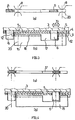
- 1 eine Anschlussvorrichtung für einen Stromzähler nach der Erfindung in einer perspektivischen Ansicht,
- Fig. 2
- eine in dem Stromzähler von
Fig. 1 verwendete Schieberplatte nach der Erfindung in perspektivischer Ansicht, - Fig. 3 bis 5
- Darstellungen, welche die Verbindung eines Zählers mit Anschlusselementen der Anschlussvorrichtung von
Fig. 1 erläutern, und - Fig. 6
- eine Teildarstellung der Schieberplatte von
Fig. 2 . - An einander gegenüberliegenden Rändern des Kastenteils 1 sind jeweils zwei Steckschlitze 7 gebildet, in welche von der Rückseite des Stromzählers 3 vorstehende Hakenelemente (nicht gezeigt) für die mechanische Befestigung des Stromzählers an der Anschlussvorrichtung einsteckbar sind.
- Die Kontaktstücke 6 lassen sich mit hinter der Tragplatte 4 angeordneten Anschlusselementen 8 verbinden, welche in den
Fig. 3 bis 5 schematisch dargestellt sind. Von den Anschlusselementen 8 führen nicht gezeigte Verbindungsstücke zu dem Anschlussleistenteil 2. Zwischen den Anschlusselementen 8 und der Tragplatte 4 ist eine inFig. 2 gesondert dargestellte Schieberplatte 9 angeordnet. In der Schieberplatte 9 sind den Schlitzöffnungen 5 und der Öffnung 18 entsprechende Öffnungen 10 bzw. 19 für den Durchtritt der Kontaktstücke des Zählers 3 gebildet. - Die schlitzförmigen Öffnungen 10 weisen jeweils eine Aufweitung 11 auf, deren Querschnitt dem Querschnitt der Kontaktstücke 6 entspricht. Von der Platte stehen Mitnehmer 12 vor, deren Funktion weiter unten anhand der
Fig. 3 bis 5 näher erläutert wird. - Die hinter der Tragplatte 4 angeordnete Schieberplatte 9 lässt sich innerhalb des Kastenteils 1 in nicht gezeigten Führungen gemäß Pfeil 13 in Längsrichtung der Schlitze 5 und gemäß Pfeil 14 senkrecht zu dieser Richtung verschieben.
- Die Anschlusselemente 8 jeder Stromphase lassen sich jeweils durch ein Überbrückungsteil 15 kurzschließen, wie es aus den
Fig. 3 bis 5 hervorgeht. Das Überbrückungsteil 15 weist die Form eines Blechstreifens mit einer Abwinklung 16 auf, wobei die Abwinklung 16 in den jeweiligenFig. 3a bis 5a der Einfachheit halber nicht dargestellt ist. - In einen rechteckförmigen Randausschnitt 17 des Überbrückungsteils 15 greift eines der beiden Kontaktstücke 6 jeder Stromphase ohne elektrischen Kontakt zum Überbrückungsteil ein.
- Wie
Fig. 3 erkennen lässt, liegt an beiden Enden des Überbrückungsteils ein Mitnehmer 12 gegen die Randabwinklung 16 des Überbrückungsteils 15 an. - In den jeweiligen
Fig. 3b bis 5b sind die Anschlusselemente 8 der Einfachheit halber weggelassen. Ihre Lage ist jedoch durch Strichlinien 20 angedeutet. Die gezeigte Schnittdarstellung entspricht z.B. dem Schnitt I-I vonFig. 1 . - In der in
Fig. 3 gezeigten Stellung ist der Zähler 3 auf die Tragplatte aufgesetzt. Die (nicht gezeigten) Hakenelemente stecken in den Schlitzen 7 am Rand des Kastenteils 1. Die Anschlusselemente 8 sind durch das Überbrückungsteil noch kurzgeschlossen. - Zur mechanischen und elektrischen Verbindung des Stromzählers 3 mit der Anschlussvorrichtung lässt sich der Zähler nun gemäß Pfeil 13 parallel zur Tragplatte 4 verschieben, wobei die Kontaktstücke 6, welche in die Aufweitung 11 der Öffnungen 10 eingreifen, die Schieberplatte 9 mitnehmen und die Schieberplatte 9 ihrerseits über die betreffenden Mitnehmer 12 die jeweiligen Überbrückungsteile 15 verschiebt. In der Anschlussstellung des Zählers, wie sie in
Fig. 4 gezeigt ist, stehen die Kontaktstücke 6 im Kontakt mit den Anschlusselementen 8. Der Kurzschluss zwischen den Anschlusselementen 8 durch das Überbrückungsteil 15 ist aufgehoben. - Die
Fig. 5 und 6b zeigen einen Zustand, in welchem die Überbrückungsteile 15 die inFig. 4 gezeigte Position und die Kontaktstücke 6 die inFig. 3 gezeigte Position einnehmen. Dieser Zustand lässt sich dadurch herstellen, dass die Schieberplatte in der inFig. 4 gezeigten Stellung gemäß Pfeil 14 senkrecht zur Richtung des Pfeils 13 verschoben wird. Nicht gezeigte Einrichtungen zur Bewegung der Schieberplatte können durch den Stromzähler abgedeckt sein, so dass die Platte nur bei abgenommenem Zähler verschiebbar ist. Es wäre aber auch möglich, am Kastenteil 1 seitlich Einrichtungen vorzusehen, die eine Verschiebung der Platte auch bei aufgesetztem Zähler ermöglichen. Bei abgesetztem Zähler lässt sich die Schieberplatte in Richtung des Pfeils 13 mit Hilfe eines Werkzeugs bewegen, das dem Boden des Stromzählers entspricht, jedoch keine in Schlitze 7 einsteckbaren Verhakungselemente aufweist. Bei der Verschiebung gelangt das jeweilige Kontaktstück 6 aus der inFig. 6a gezeigten Position in die inFig. 6b gezeigte Position. Der Zähler 3 kann nun auf der Tragplatte 4 gemäß Pfeil 13 hin und her bewegt werden, ohne die Schieberplatte 9 mitzunehmen, d.h. das betreffende Kontaktstück 6 bewegt sich in der schlitzförmigen Öffnung 10 außerhalb der Aufweitung 11. Die Randausnehmung 17 ist so bemessen, dass es bei der Hin- und Herbewegung nicht zum Anstoß des Kontaktstücks 6 gegen das Überbrückungsteil 15 kommt und zwischen Kontaktstück 6 und Überbrückungsteil 15 ein Luftspalt verbleibt. - Über die Position gemäß
Fig. 5 und 6b hinaus lässt sich die Schieberplatte 9 bei abgenommenen Zähler in der Ansicht vonFig. 6 nach rechts in eine Verschlussposition verschieben, in welcher die Schlitzöffnungen 5,18 in der Tragplatte 4 durch die gegen die Tragplatte 4 anliegende Schieberplatte 9 rückseitig verschlossen sind. Die Anschlusselemente 8 und die genannten Verbindungsteile sind dann berührungssicher abgedeckt und gegen unberechtigte Stromentnahme gesichert. - Der in
Fig. 5 gezeigte Zustand, in welchem das Überbrückungsteil 15 nicht aktivierbar ist, kann z.B. nach Montage der Anschlussvorrichtung und vor dem Anschluss eines Stromzähler bestehen, so dass während dieser Zeit eine Stromentnahme nicht möglich ist. Die betreffende Verschiebungsstellung der Schieberplatte 9 kann aber auch bei angeschlossenem Zähler eingenommen werden, wenn der Verdacht besteht, dass an der Anschlussvorrichtung Manipulationen vorgenommen werden. - Beide Verschiebungspositionen der Schieberplatte 9 gemäß Pfeil 14 können über nicht gezeigte Einrichtungen arretier- und plombierbar sein.
- In der Schieberplatte 9 lässt sich ein Fenster bilden, in welches ein von der Schieberplatte 9 vorstehendes Griffstück für die Bewegung der Schieberplatte hineinragt. Die jeweilige Stellung der Schieberplatte ließe sich durch Skalenstriche an der Schieberund Tragplatte im Bereich des Fensters kenntlich machen.
- Zur Verschiebung der Platte könnte auch ein am Längsrand des Kastenteils 1 angeordneter Exzenter dienen, der ggf. in verschiedenen Stellungen arretier- und plombierbar ist.
- Zur Führung der Schieberplatte 9 gemäß den Pfeilen 13,14 können Führungsschlitze vorgesehen sein, die zueinander im rechten Winkel stehen, wobei die Führungsschlitze derart angeordnet sind, dass die Platte nur in der in
Fig. 5 gezeigten Verschiebungsposition gemäß Pfeil 13 in Richtung des Pfeils 14 verschiebbar ist. - Alternativ zu der beschriebenen Ausführungsform, in welcher die Schieberplatte von den Kontaktstücken abkoppelbar ist, könnten auch die Schieberplatte und das Überbrückungsteil entkoppelbar sein, indem durch Bewegung der Schieberplatte in Richtung des Pfeils 14 die Mitnehmer 12 in eine zum Überbrückungsteil versetzte Stellung gebracht werden. In einer solchen Ausführungsform könnte z.B. die Abwinklung 16 entfallen und die Mitnehmer 12 in Richtung des Pfeils 13 mit den Öffnungen 10 fluchtend angeordnet sein. Die Öffnungen 10 haben dann eine einheitliche Breite, die wenigstens gleich der doppelten Stärke der Kontaktstücke entspricht.
Claims (10)
- Anschlussvorrichtung für einen Stromzähler (3), der ein Gehäuse aufweist, von dessen gegen eine Tragplatte (4) der Anschlussvorrichtung anlegbarem Boden durch Öffnungen (5, 18) in der Tragplatte (4) hindurchführbare Kontaktstücke (6) entsprechend wenigstens einer Stromphase vorstehen, welche mit stromzuund -abführenden Anschlusselementen (8) der Anschlussvorrichtung durch Verschiebung des Stromzählers (3) auf der Tragplatte (4) auf der dem Stromzähler (3) abgewandten Seite der Tragplatte (4) verbindbar sind, wobei
ein auf der dem Stromzähler (3) abgewandten Seite der Tragplatte (4) angeordneter, parallel zur Tragplatte (4) bewegbarer und Öffnungen (10, 19) aufweisender Schieber (9) der Anschlussvorrichtung vorgesehen ist, dessen Öffnungen (10, 19) in einer ersten Stellung des Schiebers (9) zu den Öffnungen (5, 18) in der Tragplatte (4) ausgerichtet sind und welcher in einer zweiten Stellung die Öffnungen (5, 18) in der Tragplatte (4) verschließt,
und der Schieber in der ersten Stellung durch die Kontaktstücke (6), welche gegen den jeweiligen Rand der Öffnungen (10) des Schiebers (9) anlegbar sind, der Schieber in der ersten Stellung durch bei Verschiebung des Stromzählers (3) auf der Tragplatte (4) mitbewegt wird und der Schieber seinerseits Mitnehmer (12) zur Mitbewegung eines die Anschlusselemente (8) kurzschließenden Überbrückungsteils (15) der Anschlussvorrichtung aus einer Überbrückungsstellung in eine Offenstellung aufweist - Anschlussvorrichtung nach Anspruch 1,
dadurch gekennzeichnet,
dass die Öffnungen (5) in der Tragplatte (4) längliche Öffnungen sind und der Schieber (9) quer zur Längsachse der Öffnungen (5, 18) aus der ersten in die zweite Stellung bewegbar ist. - Anschlussvorrichtung nach Anspruch 1 oder 2,
dadurch gekennzeichnet,
dass das Überbrückungsteil (15) eine Randausnehmung (17) aufweist, in welche eines der Kontaktstücken (6) ohne elektrischen Kontakt zu dem Überbrückungsteil (15) eingreift. - Anschlussvorrichtung nach einem der Ansprüche 1 bis 3,
dadurch gekennzeichnet,
dass der Schieber (9) durch die Kontaktstücke (6) in einer Richtung bewegbar ist, die senkrecht zur Richtung der Bewegung des Schiebers (9) von der ersten in die zweite Stellung ist. - Anschlussvorrichtung nach Anspruch 3 oder 4,
dadurch gekennzeichnet,
dass die Öffnungen (10) im Schieber (9) derart gestaltet sind, dass in einer dritten Stellung des Schiebers (9) das betreffende Kontaktstüok (6) sich bei Verschiebung des Stromzählers (3) auf der Tragplatte (4) in der Öffnung (10), ohne den Schieber (9) mitzubewegen, frei bewegen kann. - Anschlussvorrichtung nach Anspruch 5 in Kombination mit Anspruch 3,
dadurch gekennzeichnet,
dass die Randausnehmung (17) eine solche Länge hat, dass sich das Kontaktstück (6) bei der Verschiebung des Stromzählers (3) auf der Tragplatte (4) in der Randausnehmung (17) frei bewegen kann. - Anschlussvorrichtung nach Anspruch 5 oder 6,
dadurch gekennzeichnet,
dass die dritte Stellung zwischen der ersten und zweiten Stellung liegt. - Anschlussvorrichtung nach einem der Ansprüche 3 bis 7,
dadurch gekennzeichnet,
dass der Schieber (9) nur in der Offenstellung des Überbrückungsteils (15) in die zweite und/oder dritte Stellung bewegbar ist - Anschlussvorrichtung nach einem der Ansprüche 5 bis 8,
dadurch gekennzeichnet,
dass der Schieber (9) in der zweiten und/oder dritten Stellungmittels einer Arretierung der Ansclussvorrichtung arretierbar und vorzugsweise die Arretierung plombierbar ist. - Anschlussvorrichtung nach einem der Ansprüche 1 bis 9,
dadurch gekennzeichnet,
dass sie eine Einrichtung zur Anzeige der Stellung des Schiebers (9) oder/und des Überbrückungsteils (15) aufweist.
Applications Claiming Priority (4)
| Application Number | Priority Date | Filing Date | Title |
|---|---|---|---|
| DE20319726U | 2003-12-17 | ||
| DE20319726 | 2003-12-17 | ||
| DE102004002856 | 2004-01-19 | ||
| DE102004002856A DE102004002856A1 (de) | 2003-12-17 | 2004-01-19 | Anschlussvorrichtung für einen Stromzähler |
Publications (2)
| Publication Number | Publication Date |
|---|---|
| EP1544629A1 EP1544629A1 (de) | 2005-06-22 |
| EP1544629B1 true EP1544629B1 (de) | 2016-06-15 |
Family
ID=34524266
Family Applications (1)
| Application Number | Title | Priority Date | Filing Date |
|---|---|---|---|
| EP04028524.9A Expired - Lifetime EP1544629B1 (de) | 2003-12-17 | 2004-12-02 | Anschlussvorrichtung für einen Stromzähler |
Country Status (1)
| Country | Link |
|---|---|
| EP (1) | EP1544629B1 (de) |
Families Citing this family (2)
| Publication number | Priority date | Publication date | Assignee | Title |
|---|---|---|---|---|
| FR2898220B1 (fr) * | 2006-03-01 | 2011-06-10 | Mecelec Sa | Enveloppe pour compteur electrique |
| DE102006038739A1 (de) * | 2006-08-17 | 2008-03-20 | Abb Patent Gmbh | Plattform zum Aufstecken eines Stromzählers |
Citations (6)
| Publication number | Priority date | Publication date | Assignee | Title |
|---|---|---|---|---|
| DE8519135U1 (de) * | 1985-07-02 | 1985-11-07 | Isotronic Dieter Mezger, 7000 Stuttgart | Kindersicherung für Steckdosen |
| EP0763875A1 (de) * | 1995-09-15 | 1997-03-19 | Schneider Electric Sa | Elektrische Steckdose mit Verschlüsselungssystem |
| DE29901587U1 (de) * | 1998-02-06 | 1999-07-29 | Schafar, Zoltan, 51674 Wiehl | Sicherheitssteckdose |
| DE10054771A1 (de) * | 2000-10-23 | 2002-05-02 | Geyer Ag | Befestigungs- und Kontaktiereinrichtung |
| DE10216209C1 (de) * | 2002-04-12 | 2003-07-10 | Abb Patent Gmbh | Berührungsschutzvorrichtung mit Längsschieber für eine elektrische Steckdose |
| DE10313999A1 (de) * | 2003-03-27 | 2004-10-07 | Hager Electro Gmbh | Anschlussvorrichtung für einen Stromzähler |
Family Cites Families (6)
| Publication number | Priority date | Publication date | Assignee | Title |
|---|---|---|---|---|
| DE1051968B (de) * | 1957-09-06 | 1959-03-05 | Licentia Gmbh | Verschluss- und Plombenanordnung bei Klemmenbloecken fuer Elektrizitaetszaehler |
| FR2461377A1 (fr) | 1979-07-11 | 1981-01-30 | Avice Pierre | Adaptateur et prise de courant de securite comportant cet adaptateur |
| DE9313573U1 (de) * | 1993-09-09 | 1994-04-21 | Bender, Klaus Dieter, 24955 Harrislee | Vorrichtung zum Messen der elektrischen Leistung |
| DE9406938U1 (de) * | 1994-03-29 | 1995-09-07 | Landis & Gyr Business Support Ag, Zug | Meßgerät mit einem Anschlußklemmen aufweisenden Klemmenblock |
| DE10052998B4 (de) | 2000-10-24 | 2004-10-07 | Hager Electro Gmbh | Aufnahmeplattform für eine Stromzählereinheit |
| DE202004009456U1 (de) * | 2004-06-08 | 2004-09-09 | Geyer Ag | Schutzeinrichtung gegen unbefugtes Bedienen oder Entnehmen eines elektronischen Elektrizitätszählers |
-
2004
- 2004-12-02 EP EP04028524.9A patent/EP1544629B1/de not_active Expired - Lifetime
Patent Citations (6)
| Publication number | Priority date | Publication date | Assignee | Title |
|---|---|---|---|---|
| DE8519135U1 (de) * | 1985-07-02 | 1985-11-07 | Isotronic Dieter Mezger, 7000 Stuttgart | Kindersicherung für Steckdosen |
| EP0763875A1 (de) * | 1995-09-15 | 1997-03-19 | Schneider Electric Sa | Elektrische Steckdose mit Verschlüsselungssystem |
| DE29901587U1 (de) * | 1998-02-06 | 1999-07-29 | Schafar, Zoltan, 51674 Wiehl | Sicherheitssteckdose |
| DE10054771A1 (de) * | 2000-10-23 | 2002-05-02 | Geyer Ag | Befestigungs- und Kontaktiereinrichtung |
| DE10216209C1 (de) * | 2002-04-12 | 2003-07-10 | Abb Patent Gmbh | Berührungsschutzvorrichtung mit Längsschieber für eine elektrische Steckdose |
| DE10313999A1 (de) * | 2003-03-27 | 2004-10-07 | Hager Electro Gmbh | Anschlussvorrichtung für einen Stromzähler |
Non-Patent Citations (2)
| Title |
|---|
| ANONYMOUS: "EHZ VDN-LASTENHEFT ELEKTRONISCHE HAUSHALTSZAEHLER", VDN - LASTENHEFT ELEKTRONISCHE HAUSHALTSZAEHLER, XX, XX, vol. V1.01, 20 June 2004 (2004-06-20), pages 1 - 41, XP007900451 * |
| WISY M: "VDN - LASTENHEFT ELEKTRONISCHE HAUSHALTSZAEHLER, PASSAGE", VDN - LASTENHEFT ELEKTRONISCHE HAUSHALTSZAEHLER, XX, XX, vol. .5, 10 April 2003 (2003-04-10), pages 1 - 22, XP008062908 * |
Also Published As
| Publication number | Publication date |
|---|---|
| EP1544629A1 (de) | 2005-06-22 |
Similar Documents
| Publication | Publication Date | Title |
|---|---|---|
| DE10216913A1 (de) | Anschlussleiste | |
| DE102004043827A1 (de) | Vorrichtung zum Verriegeln von Elektrogeräten, insbesondere von Elektrowerkzeugen, mit Batteriepacks zur Stromversorgung | |
| EP1431765B1 (de) | Vorrichtung zur Ankopplung eines Stromzählers an eine Trägerplattform | |
| WO2017182033A1 (de) | Anordnung für die berührungssichere kontaktierung eines stromsammelschienensystems | |
| EP0762581B1 (de) | Vorrichtung zum Befestigen eines elektrischen Gerätes auf einem Adapter | |
| DE2901246C2 (de) | Elektrische Schaltvorrichtung | |
| EP1586908B1 (de) | Anschlussvorrichtung für einen Stromzähler | |
| AT517769B1 (de) | Energiezähler-Anschlussklemmenblock mit Überbrückungsvorrichtung | |
| EP1763047A2 (de) | Auswechselbare Löschblechkassette für einen Leistungsschalter sowie Leistungsschalter mit auswechselbarer Löschblechkassette | |
| EP1544629B1 (de) | Anschlussvorrichtung für einen Stromzähler | |
| DE4011447C2 (de) | Vorrichtung zur Schnappbefestigung eines elektrischen Installationsgerätes | |
| DE3113635C1 (de) | Elektromagnetisches Relais | |
| DE3441890C2 (de) | ||
| EP1462808B1 (de) | Anschlussvorrichtung für einen Stromzähler | |
| DE19748553A1 (de) | Einschub für einen elektrischen Schaltschrank | |
| DE2712893A1 (de) | Gehaeuse, insbesondere fuer elektrische schaltgeraete, mit schienen- und schraubbefestigung | |
| DE102004002856A1 (de) | Anschlussvorrichtung für einen Stromzähler | |
| EP1544627B1 (de) | Anschlussvorrichtung für einen Stromzähler | |
| EP1657555B1 (de) | Plattform zum Aufstecken eines Stromzählers | |
| DE9010565U1 (de) | Steckverbinder | |
| DE3243134C2 (de) | ||
| EP0678883B1 (de) | Elektrischer Kleinschalter | |
| EP1220372A2 (de) | Steckverbinder-Gehäuse mit Kodiereinrichtung | |
| DE4440902C2 (de) | Elektrischer Kleinschalter | |
| DE2102385A1 (de) | Tastenschalter-Tableau-Mechanik |
Legal Events
| Date | Code | Title | Description |
|---|---|---|---|
| PUAI | Public reference made under article 153(3) epc to a published international application that has entered the european phase |
Free format text: ORIGINAL CODE: 0009012 |
|
| AK | Designated contracting states |
Kind code of ref document: A1 Designated state(s): AT BE BG CH CY CZ DE DK EE ES FI FR GB GR HU IE IS IT LI LT LU MC NL PL PT RO SE SI SK TR |
|
| AX | Request for extension of the european patent |
Extension state: AL BA HR LV MK YU |
|
| 17P | Request for examination filed |
Effective date: 20051205 |
|
| AKX | Designation fees paid |
Designated state(s): AT BE BG CH CY CZ DE DK EE ES FI FR GB GR HU IE IS IT LI LT LU MC NL PL PT RO SE SI SK TR |
|
| REG | Reference to a national code |
Ref country code: DE Ref legal event code: R079 Ref document number: 502004015228 Country of ref document: DE Free format text: PREVIOUS MAIN CLASS: G01R0011240000 Ipc: G01R0022060000 |
|
| GRAP | Despatch of communication of intention to grant a patent |
Free format text: ORIGINAL CODE: EPIDOSNIGR1 |
|
| INTG | Intention to grant announced |
Effective date: 20160104 |
|
| RIC1 | Information provided on ipc code assigned before grant |
Ipc: G01R 22/06 20060101AFI20151214BHEP |
|
| RIN1 | Information on inventor provided before grant (corrected) |
Inventor name: ZIMMERMANN, MICHAEL Inventor name: CLEMENS, GUNTRAM, DR.-ING. Inventor name: KELAIDITIS, KONSTANTIN, DR.-ING. |
|
| GRAS | Grant fee paid |
Free format text: ORIGINAL CODE: EPIDOSNIGR3 |
|
| GRAA | (expected) grant |
Free format text: ORIGINAL CODE: 0009210 |
|
| AK | Designated contracting states |
Kind code of ref document: B1 Designated state(s): AT BE BG CH CY CZ DE DK EE ES FI FR GB GR HU IE IS IT LI LT LU MC NL PL PT RO SE SI SK TR |
|
| REG | Reference to a national code |
Ref country code: CH Ref legal event code: EP Ref country code: GB Ref legal event code: FG4D Free format text: NOT ENGLISH |
|
| REG | Reference to a national code |
Ref country code: IE Ref legal event code: FG4D Free format text: LANGUAGE OF EP DOCUMENT: GERMAN |
|
| REG | Reference to a national code |
Ref country code: AT Ref legal event code: REF Ref document number: 806763 Country of ref document: AT Kind code of ref document: T Effective date: 20160715 |
|
| REG | Reference to a national code |
Ref country code: DE Ref legal event code: R096 Ref document number: 502004015228 Country of ref document: DE |
|
| REG | Reference to a national code |
Ref country code: CH Ref legal event code: NV Representative=s name: ALDO ROEMPLER PATENTANWALT, CH |
|
| REG | Reference to a national code |
Ref country code: LT Ref legal event code: MG4D |
|
| REG | Reference to a national code |
Ref country code: NL Ref legal event code: MP Effective date: 20160615 |
|
| PG25 | Lapsed in a contracting state [announced via postgrant information from national office to epo] |
Ref country code: FI Free format text: LAPSE BECAUSE OF FAILURE TO SUBMIT A TRANSLATION OF THE DESCRIPTION OR TO PAY THE FEE WITHIN THE PRESCRIBED TIME-LIMIT Effective date: 20160615 Ref country code: LT Free format text: LAPSE BECAUSE OF FAILURE TO SUBMIT A TRANSLATION OF THE DESCRIPTION OR TO PAY THE FEE WITHIN THE PRESCRIBED TIME-LIMIT Effective date: 20160615 |
|
| PG25 | Lapsed in a contracting state [announced via postgrant information from national office to epo] |
Ref country code: GR Free format text: LAPSE BECAUSE OF FAILURE TO SUBMIT A TRANSLATION OF THE DESCRIPTION OR TO PAY THE FEE WITHIN THE PRESCRIBED TIME-LIMIT Effective date: 20160916 Ref country code: NL Free format text: LAPSE BECAUSE OF FAILURE TO SUBMIT A TRANSLATION OF THE DESCRIPTION OR TO PAY THE FEE WITHIN THE PRESCRIBED TIME-LIMIT Effective date: 20160615 Ref country code: SE Free format text: LAPSE BECAUSE OF FAILURE TO SUBMIT A TRANSLATION OF THE DESCRIPTION OR TO PAY THE FEE WITHIN THE PRESCRIBED TIME-LIMIT Effective date: 20160615 |
|
| REG | Reference to a national code |
Ref country code: FR Ref legal event code: PLFP Year of fee payment: 13 |
|
| PG25 | Lapsed in a contracting state [announced via postgrant information from national office to epo] |
Ref country code: EE Free format text: LAPSE BECAUSE OF FAILURE TO SUBMIT A TRANSLATION OF THE DESCRIPTION OR TO PAY THE FEE WITHIN THE PRESCRIBED TIME-LIMIT Effective date: 20160615 Ref country code: IT Free format text: LAPSE BECAUSE OF FAILURE TO SUBMIT A TRANSLATION OF THE DESCRIPTION OR TO PAY THE FEE WITHIN THE PRESCRIBED TIME-LIMIT Effective date: 20160615 Ref country code: IS Free format text: LAPSE BECAUSE OF FAILURE TO SUBMIT A TRANSLATION OF THE DESCRIPTION OR TO PAY THE FEE WITHIN THE PRESCRIBED TIME-LIMIT Effective date: 20161015 Ref country code: RO Free format text: LAPSE BECAUSE OF FAILURE TO SUBMIT A TRANSLATION OF THE DESCRIPTION OR TO PAY THE FEE WITHIN THE PRESCRIBED TIME-LIMIT Effective date: 20160615 Ref country code: CZ Free format text: LAPSE BECAUSE OF FAILURE TO SUBMIT A TRANSLATION OF THE DESCRIPTION OR TO PAY THE FEE WITHIN THE PRESCRIBED TIME-LIMIT Effective date: 20160615 Ref country code: SK Free format text: LAPSE BECAUSE OF FAILURE TO SUBMIT A TRANSLATION OF THE DESCRIPTION OR TO PAY THE FEE WITHIN THE PRESCRIBED TIME-LIMIT Effective date: 20160615 |
|
| PGFP | Annual fee paid to national office [announced via postgrant information from national office to epo] |
Ref country code: CH Payment date: 20161227 Year of fee payment: 13 |
|
| PG25 | Lapsed in a contracting state [announced via postgrant information from national office to epo] |
Ref country code: PT Free format text: LAPSE BECAUSE OF FAILURE TO SUBMIT A TRANSLATION OF THE DESCRIPTION OR TO PAY THE FEE WITHIN THE PRESCRIBED TIME-LIMIT Effective date: 20161017 Ref country code: ES Free format text: LAPSE BECAUSE OF FAILURE TO SUBMIT A TRANSLATION OF THE DESCRIPTION OR TO PAY THE FEE WITHIN THE PRESCRIBED TIME-LIMIT Effective date: 20160615 |
|
| PGFP | Annual fee paid to national office [announced via postgrant information from national office to epo] |
Ref country code: PL Payment date: 20161121 Year of fee payment: 13 Ref country code: AT Payment date: 20161121 Year of fee payment: 13 |
|
| REG | Reference to a national code |
Ref country code: DE Ref legal event code: R097 Ref document number: 502004015228 Country of ref document: DE |
|
| PLBE | No opposition filed within time limit |
Free format text: ORIGINAL CODE: 0009261 |
|
| STAA | Information on the status of an ep patent application or granted ep patent |
Free format text: STATUS: NO OPPOSITION FILED WITHIN TIME LIMIT |
|
| 26N | No opposition filed |
Effective date: 20170316 |
|
| PG25 | Lapsed in a contracting state [announced via postgrant information from national office to epo] |
Ref country code: BE Free format text: LAPSE BECAUSE OF NON-PAYMENT OF DUE FEES Effective date: 20161231 Ref country code: DK Free format text: LAPSE BECAUSE OF FAILURE TO SUBMIT A TRANSLATION OF THE DESCRIPTION OR TO PAY THE FEE WITHIN THE PRESCRIBED TIME-LIMIT Effective date: 20160615 |
|
| GBPC | Gb: european patent ceased through non-payment of renewal fee |
Effective date: 20161202 |
|
| PG25 | Lapsed in a contracting state [announced via postgrant information from national office to epo] |
Ref country code: SI Free format text: LAPSE BECAUSE OF FAILURE TO SUBMIT A TRANSLATION OF THE DESCRIPTION OR TO PAY THE FEE WITHIN THE PRESCRIBED TIME-LIMIT Effective date: 20160615 |
|
| PG25 | Lapsed in a contracting state [announced via postgrant information from national office to epo] |
Ref country code: MC Free format text: LAPSE BECAUSE OF FAILURE TO SUBMIT A TRANSLATION OF THE DESCRIPTION OR TO PAY THE FEE WITHIN THE PRESCRIBED TIME-LIMIT Effective date: 20160615 |
|
| REG | Reference to a national code |
Ref country code: IE Ref legal event code: MM4A |
|
| PG25 | Lapsed in a contracting state [announced via postgrant information from national office to epo] |
Ref country code: LU Free format text: LAPSE BECAUSE OF NON-PAYMENT OF DUE FEES Effective date: 20161202 |
|
| PG25 | Lapsed in a contracting state [announced via postgrant information from national office to epo] |
Ref country code: IE Free format text: LAPSE BECAUSE OF NON-PAYMENT OF DUE FEES Effective date: 20161202 Ref country code: GB Free format text: LAPSE BECAUSE OF NON-PAYMENT OF DUE FEES Effective date: 20161202 |
|
| REG | Reference to a national code |
Ref country code: FR Ref legal event code: PLFP Year of fee payment: 14 |
|
| REG | Reference to a national code |
Ref country code: BE Ref legal event code: MM Effective date: 20161231 |
|
| PG25 | Lapsed in a contracting state [announced via postgrant information from national office to epo] |
Ref country code: CY Free format text: LAPSE BECAUSE OF FAILURE TO SUBMIT A TRANSLATION OF THE DESCRIPTION OR TO PAY THE FEE WITHIN THE PRESCRIBED TIME-LIMIT Effective date: 20160615 Ref country code: HU Free format text: LAPSE BECAUSE OF FAILURE TO SUBMIT A TRANSLATION OF THE DESCRIPTION OR TO PAY THE FEE WITHIN THE PRESCRIBED TIME-LIMIT; INVALID AB INITIO Effective date: 20041202 |
|
| PG25 | Lapsed in a contracting state [announced via postgrant information from national office to epo] |
Ref country code: TR Free format text: LAPSE BECAUSE OF FAILURE TO SUBMIT A TRANSLATION OF THE DESCRIPTION OR TO PAY THE FEE WITHIN THE PRESCRIBED TIME-LIMIT Effective date: 20160615 |
|
| PG25 | Lapsed in a contracting state [announced via postgrant information from national office to epo] |
Ref country code: BG Free format text: LAPSE BECAUSE OF FAILURE TO SUBMIT A TRANSLATION OF THE DESCRIPTION OR TO PAY THE FEE WITHIN THE PRESCRIBED TIME-LIMIT Effective date: 20160615 |
|
| REG | Reference to a national code |
Ref country code: CH Ref legal event code: PL |
|
| REG | Reference to a national code |
Ref country code: AT Ref legal event code: MM01 Ref document number: 806763 Country of ref document: AT Kind code of ref document: T Effective date: 20171202 |
|
| PG25 | Lapsed in a contracting state [announced via postgrant information from national office to epo] |
Ref country code: AT Free format text: LAPSE BECAUSE OF NON-PAYMENT OF DUE FEES Effective date: 20171202 Ref country code: LI Free format text: LAPSE BECAUSE OF NON-PAYMENT OF DUE FEES Effective date: 20171231 Ref country code: CH Free format text: LAPSE BECAUSE OF NON-PAYMENT OF DUE FEES Effective date: 20171231 |
|
| PGFP | Annual fee paid to national office [announced via postgrant information from national office to epo] |
Ref country code: FR Payment date: 20181226 Year of fee payment: 15 |
|
| PGFP | Annual fee paid to national office [announced via postgrant information from national office to epo] |
Ref country code: DE Payment date: 20181231 Year of fee payment: 15 |
|
| PG25 | Lapsed in a contracting state [announced via postgrant information from national office to epo] |
Ref country code: PL Free format text: LAPSE BECAUSE OF NON-PAYMENT OF DUE FEES Effective date: 20171202 |
|
| REG | Reference to a national code |
Ref country code: DE Ref legal event code: R119 Ref document number: 502004015228 Country of ref document: DE |
|
| PG25 | Lapsed in a contracting state [announced via postgrant information from national office to epo] |
Ref country code: DE Free format text: LAPSE BECAUSE OF NON-PAYMENT OF DUE FEES Effective date: 20200701 Ref country code: FR Free format text: LAPSE BECAUSE OF NON-PAYMENT OF DUE FEES Effective date: 20191231 |