EP1544403B1 - Flügel, insbesondere eines Fensters, einer Tür oder einer Wand - Google Patents
Flügel, insbesondere eines Fensters, einer Tür oder einer Wand Download PDFInfo
- Publication number
- EP1544403B1 EP1544403B1 EP04029415A EP04029415A EP1544403B1 EP 1544403 B1 EP1544403 B1 EP 1544403B1 EP 04029415 A EP04029415 A EP 04029415A EP 04029415 A EP04029415 A EP 04029415A EP 1544403 B1 EP1544403 B1 EP 1544403B1
- Authority
- EP
- European Patent Office
- Prior art keywords
- clamping
- plate
- wing
- profile
- screw
- Prior art date
- Legal status (The legal status is an assumption and is not a legal conclusion. Google has not performed a legal analysis and makes no representation as to the accuracy of the status listed.)
- Revoked
Links
- 230000015572 biosynthetic process Effects 0.000 claims description 5
- 238000005755 formation reaction Methods 0.000 claims description 5
- 230000000295 complement effect Effects 0.000 claims description 4
- 239000011521 glass Substances 0.000 abstract description 6
- 238000005452 bending Methods 0.000 abstract description 3
- 238000004519 manufacturing process Methods 0.000 description 3
- 125000006850 spacer group Chemical group 0.000 description 3
- 230000005489 elastic deformation Effects 0.000 description 2
- 239000000463 material Substances 0.000 description 2
- 230000004308 accommodation Effects 0.000 description 1
- 230000006978 adaptation Effects 0.000 description 1
- 239000011248 coating agent Substances 0.000 description 1
- 238000000576 coating method Methods 0.000 description 1
- 230000001687 destabilization Effects 0.000 description 1
- 238000005516 engineering process Methods 0.000 description 1
- 230000014759 maintenance of location Effects 0.000 description 1
- 230000003287 optical effect Effects 0.000 description 1
- 230000035515 penetration Effects 0.000 description 1
- 238000007789 sealing Methods 0.000 description 1
- 238000010408 sweeping Methods 0.000 description 1
Images
Classifications
-
- E—FIXED CONSTRUCTIONS
- E06—DOORS, WINDOWS, SHUTTERS, OR ROLLER BLINDS IN GENERAL; LADDERS
- E06B—FIXED OR MOVABLE CLOSURES FOR OPENINGS IN BUILDINGS, VEHICLES, FENCES OR LIKE ENCLOSURES IN GENERAL, e.g. DOORS, WINDOWS, BLINDS, GATES
- E06B3/00—Window sashes, door leaves, or like elements for closing wall or like openings; Layout of fixed or moving closures, e.g. windows in wall or like openings; Features of rigidly-mounted outer frames relating to the mounting of wing frames
- E06B3/54—Fixing of glass panes or like plates
- E06B3/5454—Fixing of glass panes or like plates inside U-shaped section members
-
- E—FIXED CONSTRUCTIONS
- E06—DOORS, WINDOWS, SHUTTERS, OR ROLLER BLINDS IN GENERAL; LADDERS
- E06B—FIXED OR MOVABLE CLOSURES FOR OPENINGS IN BUILDINGS, VEHICLES, FENCES OR LIKE ENCLOSURES IN GENERAL, e.g. DOORS, WINDOWS, BLINDS, GATES
- E06B3/00—Window sashes, door leaves, or like elements for closing wall or like openings; Layout of fixed or moving closures, e.g. windows in wall or like openings; Features of rigidly-mounted outer frames relating to the mounting of wing frames
- E06B3/02—Wings made completely of glass
Definitions
- the invention relates to a wing, in particular a window, a door or a wall, according to the preamble of patent claim 1.
- a profile device arranged in the edge region of the wing serves to receive a plate of the wing, the profile device having a receiving groove which engages around the outer edge of the plate.
- the outer edge of the plate can be fixed by a clamping connection in the profile device by the width of the receiving groove is variable by means of an adjustment.
- the profile device is formed at least in the region of the receptacle of the plate as a one-piece profile, wherein the one-piece profile has two opposite clamping legs and a web connecting the clamping leg, through which the clamping legs are bending elastic relative to each other.
- the profile device has an integrally formed with the profile device connection area for the connection of fitting devices by the connection area has two opposite connection legs, which form a receiving space for connection of the fitting devices with the web.
- the connection of the fitting devices by means of two channels, which are arranged in the web of the profile device. The assembly of the fitting devices is therefore complicated, since with the relatively small channels corresponding fasteners must be provided.
- EP 0 313 672 A1 has a receiving space for connecting fittings on. These are connected by means of screws with the web of the profile device, ie the web must either have at appropriate positions a variety of threaded holes, or the threaded holes must be subsequently introduced at the desired positions.
- U1 From the DE 295 21 069 U1 is a door leaf with a arranged in the edge region of the wing, designed as a door rail profiling device for receiving a designed as a glass plate plate of the wing known.
- a receiving groove of the profile device engages around the outer edge of the plate, which is held in the profile device by a clamping connection by the width of the receiving groove is variable by means of an adjustment.
- the profile device has two identical profiles, which are clamped together to clamp the plate between two opposite profile legs by means of a screw. In order for the clamping device is stabilized, also a further support of the profiles with each other is necessary, which takes place via separate, mountable between the profiles spacers.
- the spacers are also used for mounting fittings on the wing, ie they must be mounted at exactly the point where the attachment of a fitting is provided. Subsequent changes in the mounting position of the spacers for adaptation to fittings to be connected are feasible only under destabilization of the mounting of the mounted plate in the profile device. The high number of items to be manufactured separately increases the manufacturing costs. The assembly of the profile device is complex because of the many items.
- the EP 0 586 840 B1 shows a fastener for adjustable attachment of a glass plate designed as a plate on a frame member.
- the integrally formed profile of a frame strip surrounds the plate in its edge region, but does not abut this, and holds the plate on this sweeping holding parts.
- the opposite legs of the profile have opposite, mutually facing grooves, in which the previously associated with the plate holding parts are inserted.
- the profile must have a high rigidity for secure retention of the holding parts.
- the disadvantage is that the plate must be laboriously provided with holes for reaching through the holding parts. This is unfavorable, especially with glass plates.
- the possibility of adjustment of the holding member relative to the plate is limited. Since there is a gap between the plate and the profile, additional sealing measures are required.
- the invention has for its object to provide a generic wing, which has a cost-producible and safe mountable profile device.
- the connecting legs of the profile device according to the invention have suitable formations for connecting the fitting devices.
- the formations of the connecting legs may be formed as webs, projections, grooves or holes.
- the profiling device can be designed as an extruded profile that can be cut to the desired length.
- a plate without holes can be used. This also reduces the assembly costs and the production costs.
- a particularly good bending elasticity of the profile device can be achieved by having certain regions of the clamping legs, for example in the vicinity of the connecting web, or the connecting web itself a smaller compared to other areas of the clamping legs cross-section. Thereby is achieved that the areas of the clamping legs, which have a larger cross-section, are not deformed.
- the adjusting device may comprise at least one screw and at least one nut, wherein the screw arranged in the clamping legs, formed as bores through openings, so that the clamping legs between the screw head of the screw and the nut are clamped.
- the opening formed as a bore of one of the two clamping legs may have an internal thread into which the screw can engage. This eliminates the need for a separate mother, which means a further reduction of assembly costs.
- the voltage applied to the screw head of the clamping jaw may have on its side facing outward in the region of the opening a recess for the screw head.
- the recess can be dimensioned so that the screw head can be actuated unhindered by an adjusting tool. This ensures that the screw head in its mounted state does not protrude beyond the cross-sectional area of the profile device.
- the voltage applied to the mother clamping leg may have on its side facing outward in the region of the opening a recess for the mother.
- the shape of the recess may be complementary to the cross section of the nut, so that there is an anti-rotation of the nut when operating the screw. In addition, it is ensured that the nut in its assembled state does not protrude beyond the cross-sectional area of the profile device.
- the inner surfaces of the clamping legs relative to the wing plane can be arranged inclined by a few degrees to each other.
- the clamping legs can be made torsionally stiff by their cross-sectional geometry be, ie a selective introduction of force into one of the clamping legs perpendicular to the longitudinal axis of the profile device causes a deflection of the clamping leg over a wide range of profile device. This ensures that the force transmitted by the tightening of a screw through the inner surfaces of the clamping legs is introduced along the entire extension of the profiling device into the plate. This linear force introduction causes a secure clamping of the plate in the profile device.
- the voltage applied to the plate inner surfaces of the clamping legs may have a Reibwerter Ecknde embodiment of its surface.
- the inner surfaces of the clamping legs may have a corrugation extending parallel to the longitudinal axis of the profile device.
- the inner surfaces of the clamping legs which bear against the plate can have a friction-increasing coating.
- an elastic intermediate layer may be arranged, in particular if the plate is made of a fragile material, for example glass.
- the elastic intermediate layer causes a distribution of the linearly introduced by the clamping legs force on a surface of the plate.
- the intermediate layer may be formed of a material with a high coefficient of friction and thus contributes to a secure fixation of the plate in the profile device.
- the elastic intermediate layer also causes a seal of the plate relative to the profile device.
- the mounted adjusting device can be optically hidden by a cover profile which can be placed on the profile device.
- the profile device can have a connection region for the connection of fitting devices, for example hinges, roller carriages, locking elements, seals, etc.
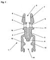
- Fig. 1 shows a profile device 1, which is provided for receiving a plate, for example a glass sheet of a wing.
- the profile device 1 which can be mounted in the edge region of the plate, can be used to connect fitting parts to the wing, for example, belts, roller carriages, locks, seals, etc.
- the profile device can also form a purely optical closure of the wing or edge protection for the plate ,
- the profile device 1 consists of a one-piece profile, which has two opposite clamping legs 2, 3 for receiving a plate and two likewise opposite connecting legs 12, 13 for connecting fitting parts.
- the clamping legs 2, 3 form with their opposite, respectively L-shaped inner surfaces 6, 7 a receiving groove 5 for the plate.
- the inner surfaces 6, 7 can be formed reibwerter bannd be. In the illustrated embodiment, they have a parallel to the longitudinal axis of the profile device 1 extending corrugation.
- the inner surfaces 6, 7 are slightly inclined to each other, so that their distance to the bottom of the receiving groove 5 is slightly increased.
- the connecting legs 12, 13 are integrally formed in the region of the web 4 to the clamping legs 2, 3, so that the connecting legs 12, 13 form with the web a receiving space 14 for fittings to be connected.
- the connecting legs 12, 13 have for this purpose grooves and projections on which the fittings to be connected can be fixed.
- the clamping legs 2, 3 have in the vicinity of the bottom of the receiving groove 5 mutually aligned pairs of holes formed as holes 8, 9.
- the profile of the clamping legs 2, 3 is provided to the outside with recesses 10, 11.
- the recess 10 of the one clamping leg 2 is formed in the form of a shallow groove, wherein the groove base is arranged perpendicular to the longitudinal axis of the opening 8.
- the shape of the recess 11 of the other clamping leg 3 corresponds in the embodiment in cross section a circle segment, but may also deviating, for example, the rectangular recess 10 of the first clamping leg 2, for example, be formed.
- the recesses 10, 11 must be located in the region of the openings 8, 9.
- the recesses 10, 11 extend over the entire length of the profile device 1.
- the pairs of openings 8, 9 may be arranged at certain intervals along the profile device 1. Alternatively, the openings 8, 9 can also be subsequently introduced manually to the respectively desired positions in the clamping legs 2, 3.
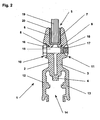
- Fig. 2 is the profile device 1 according to Fig. 1 shown with mounted plate 19.
- the plate 19 engages in the receiving groove 5 of the clamping legs 2, 3, wherein between the inner surfaces 6, 7 of the receiving groove 5 and the plate 19, an elastic intermediate layer 20 is arranged, which encloses the projecting into the receiving groove 5 edge region of the plate 19.
- the total thickness of the plate 19 with the Intermediate layer 20 is slightly smaller than the smallest distance of the inner surfaces 6, 7 in the edge region of the receiving groove. 5
- a further tightening of the screw 15 causes the clamping legs 2, 3 to move towards each other under flexurally elastic deformation. This reduces the distance of the inner surfaces 6, 7 of the receiving groove 5, so that the plate 19 is clamped under elastic deformation of the intermediate layer 20 in the receiving groove 5.
Landscapes
- Engineering & Computer Science (AREA)
- Civil Engineering (AREA)
- Structural Engineering (AREA)
- Securing Of Glass Panes Or The Like (AREA)
- Specific Sealing Or Ventilating Devices For Doors And Windows (AREA)
- Connection Of Plates (AREA)
- Window Of Vehicle (AREA)
Description
- Die Erfindung betrifft einen Flügel, insbesondere eines Fensters, einer Tür oder einer Wand, nach dem Oberbegriff des Patentanspruchs 1.
- Aus der gattungsbildenden
EP 1 094 191 A2 ist ein Flügel, insbesondere eines Fensters, einer Tür, oder einer Wand bekannt. Eine im Randbereich des Flügels angeordnete Profileinrichtung dient zur Aufnahme einer Platte des Flügels, wobei die Profileinrichtung eine Aufnahmenut aufweist, welche die Außenkante der Platte umgreift. Die Außenkante der Platte ist durch eine Klemmverbindung in der Profileinrichtung fixierbar, indem die Breite der Aufnahmenut mittels einer Einstelleinrichtung veränderbar ist. Die Profileinrichtung ist zumindest im Bereich der Aufnahme der Platte als einstückiges Profil ausgebildet, wobei das einstückige Profil zwei gegenüberliegende Klemmschenkel und einen die Klemmschenkel verbindenden Steg aufweist, durch den die Klemmschenkel biegeelastisch relativ zueinander bewegbar sind. Die Profileinrichtung weist einen einstückig mit der Profileinrichtung ausgebildeten Anschlussbereich zum Anschluss von Beschlageinrichtungen auf, indem der Anschlussbereich zwei gegenüberliegende Anschlussschenkel aufweist, welche mit dem Steg einen Aufnahmeraum zum Anschluss der Beschlageinrichtungen bilden. Der Anschluss der Beschlageinrichtungen erfolgt mittels zweier Kanäle, welche im Steg der Profileinrichtung angeordnet sind. Die Montage der Beschlageinrichtungen ist somit aufwändig, da mit den relativ kleinen Kanälen korrespondierende Befestigungselemente vorgesehen werden müssen. - Aus der
US 4,914,888 ist eine weitere nach dem Oberbegriff des Patentanspruchs 1 bekannt. Der Aufnahmeraum zum Anschluss von Beschlageinrichtungen hat keinerlei Ausformungen und bedarf somit zum Anschluss der Beschlageinrichtungen einer aufwändigen Nachbehandlung (z.B. das Eindringen von Bohrungen). - Auch der Gegenstand der
EP 0 313 672 A1 weist einen Aufnahmeraum zum Anschluss von Beschlageinrichtungen auf. Diese werden mittels Schrauben mit dem Steg der Profilreinrichtung verbunden, d.h. der Steg muss entweder an geeigneten Positionen eine Vielzahl von Gewindebohrungen aufweisen, oder die Gewindebohrungen müssen nachträglich an den gewünschten Positionen eingebracht werden. - Aus der
DE 295 21 069 U1 ist ein Türflügel mit einer im Randbereich des Flügels angeordneten, als Türschiene ausgebildeten Profileinrichtung zur Aufnahme einer als Glasscheibe ausgebildeten Platte des Flügels bekannt. Eine Aufnahmenut der Profileinrichtung umgreift die Außenkante der Platte, welche in der Profileinrichtung durch eine Klemmverbindung gehalten wird, indem die Breite der Aufnahmenut mittels einer Einstelleinrichtung veränderbar ist. Die Profileinrichtung weist zwei gleiche Profile auf, welche zur Klemmung der Platte zwischen zwei gegenüberliegenden Profilschenkeln mittels einer Verschraubung miteinander verspannt werden. Damit die Klemmeinrichtung stabilisiert wird, ist außerdem eine weitere Abstützung der Profile untereinander notwendig, welche über separate, zwischen den Profilen montierbare Distanzstücke erfolgt. Die Distanzstücke dienen außerdem auch zur Befestigung von Beschlageinrichtungen am Flügel, d.h. sie müssen an genau der Stelle montiert sein, wo die Befestigung einer Beschlageinrichtung vorgesehen ist. Nachträgliche Änderungen der Montageposition der Distanzstücke zur Anpassung an anzuschließende Beschlageinrichtungen sind nur unter Destabilisierung der Halterung der montierten Platte in der Profileinrichtung durchführbar. Die hohe Anzahl separat zu fertigender Einzelteile erhöht die Herstellkosten. Die Montage der Profileinrichtung ist aufgrund der vielen Einzelteile aufwändig. - Die
EP 0 586 840 B1 zeigt ein Befestigungselement zur justierbaren Befestigung einer als Glasscheibe ausgebildeten Platte an einem Rahmenelement. Das einstückig ausgebildete Profil einer Rahmenleiste umgreift die Platte in ihrem Randbereich, liegt aber nicht an dieser an, und hält die Platte über diese durchgreifende Halteteile. Die gegenüberliegenden Schenkel des Profils weisen gegenüberliegende, einander zugewandte Nuten auf, in welche die vorher mit der Platte verbundenen Halteteile einschiebbar sind. Das Profil muss zur sicheren Halterung der Halteteile eine hohe Steifigkeit aufweisen. Nachteilig ist es, dass die Platte aufwändig mit Bohrungen zum Durchgreifen der Halteteile versehen werden muss. Dies ist insbesondere bei Glasplatten ungünstig. Außerdem ist die Justiermöglichkeit des Halteteils gegenüber der Platte begrenzt. Da zwischen der Platte und dem Profil ein Zwischenraum vorhanden ist, sind zusätzliche Maßnahmen zur Abdichtung erforderlich. - Der Erfindung liegt die Aufgabe zugrunde, einen gattungsgemäßen Flügel zu schaffen, welcher eine kostengünstig herstellbare und sicher montierbare Profileinrichtung aufweist.
- Die Aufgabe wird durch die Merkmale des Patentanspruchs 1 gelöst. Die Unteransprüche bilden vorteilhafte Ausgestaltungsmöglichkeiten der Erfindung.
- Die Anschlussschenkel der erfindungsgemäßen Profileinrichtung weisen zum Anschluss der Beschlageinrichtungen geeignete Ausformungen auf.
- Die Ausformungen der Anschlussschenkel können als Stege, Vorsprünge, Nuten oder Bohrungen ausgebildet sein.
- Die Profileinrichtung kann als kostengünstig herstellbares, auf die gewünschte Länge ablängbares Strangpressprofil ausgebildet sein.
- Außerdem kann eine Platte ohne Bohrungen verwendet werden. Auch hierdurch werden der Montageaufwand sowie die Herstellkosten reduziert.
- Eine besonders gute Biegeelastizität der Profileinrichtung kann erreicht werden, indem bestimmte Bereiche der Klemmschenkel, beispielsweise in der Nähe des Verbindungsstegs, oder der Verbindungssteg selbst einen im Vergleich zu anderen Bereichen der Klemmschenkel geringeren Querschnitt aufweisen. Dadurch wird erreicht, dass die Bereiche der Klemmschenkel, die einen größeren Querschnitt aufweisen, nicht verformt werden.
- Mit einer konstruktiv äußerst einfach gestalteten Einstelleinrichtung ist die Justierung der Aufnahmenut dieser Profileinrichtung zur Fixierung der Platte in der Profileinrichtung durchführbar.
- Die Einstelleinrichtung kann mindestens eine Schraube sowie mindestens eine Mutter umfassen, wobei die Schraube in den Klemmschenkeln angeordnete, als Bohrungen ausgebildete Öffnungen durchgreift, so dass die Klemmschenkel zwischen dem Schraubenkopf der Schraube und der Mutter klemmbar sind.
- Alternativ kann die als Bohrung ausgebildete Öffnung eines der beiden Klemmschenkel ein Innengewinde aufweisen, in welches die Schraube eingreifen kann. Hierdurch erübrigt sich die Verwendung einer separaten Mutter, was eine weitere Reduzierung des Montageaufwands bedeutet.
- Der an dem Schraubenkopf der Schraube anliegende Klemmschenkel kann an seiner nach außen gewandten Seite im Bereich der Öffnung eine Aussparung für den Schraubenkopf aufweisen. Die Aussparung kann so bemessen sein, dass der Schraubenkopf ungehindert durch ein Verstellwerkzeug betätigbar ist. Hierdurch wird erreicht, dass der Schraubenkopf in seinem montierten Zustand nicht über die Querschnittsfläche der Profileinrichtung herausragt.
- Der an der Mutter anliegende Klemmschenkel kann an seiner nach außen gewandten Seite im Bereich der Öffnung eine Aussparung für die Mutter aufweisen. Die Ausformung der Aussparung kann mit dem Querschnitt der Mutter komplementär sein, so dass sich eine Verdrehsicherung der Mutter beim Betätigen der Schraube ergibt. Außerdem wird erreicht, dass die Mutter in ihrem montierten Zustand nicht über die Querschnittsfläche der Profileinrichtung herausrägt.
- Bei montierter Platte können die Innenflächen der Klemmschenkel gegenüber der Flügelebene um wenige Winkelgrade zueinander geneigt angeordnet sein. Die Klemmschenkel können durch ihre Querschnittsgeometrie verwindungssteif ausgebildet sein, d.h. eine punktuelle Krafteinleitung in einen der Klemmschenkel senkrecht zur Längsachse der Profileinrichtung bewirkt eine Auslenkung des Klemmschenkels über einen weiten Bereich der Profileinrichtung. Hierdurch wird erreicht, dass die durch das Anziehen einer Schraube durch die Innenflächen der Klemmschenkel übertragene Kraft entlang der gesamten Erstreckung der Profileinrichtung in die Platte eingeleitet wird. Diese linienförmige Krafteinleitung bewirkt eine sichere Klemmung der Platte in der Profileinrichtung.
- Die an der Platte anliegenden Innenflächen der Klemmschenkel können eine reibwerterhöhende Ausgestaltung ihrer Oberfläche aufweisen. Beispielsweise können die Innenflächen der Klemmschenkel eine parallel zur Längsachse der Profileinrichtung verlaufende Riffelung aufweisen. Alternativ oder zusätzlich können die an der Platte anliegenden Innenflächen der Klemmschenkel eine reibwerterhöhende Beschichtung aufweisen.
- Zwischen den Innenflächen der Klemmschenkel und der in die Aufnahmenut eingreifenden Außenfläche der Platte kann eine elastische Zwischenlage angeordnet sein, insbesondere wenn die Platte aus einem zerbrechlichen Material, beispielsweise Glas, ausgebildet ist. Die elastische Zwischenlage bewirkt eine Verteilung der durch die Klemmschenkel linienförmig eingeleiteten Kraft auf eine Fläche der Platte. Die Zwischenlage kann aus einem Material mit hohem Reibwert ausgebildet sein und trägt somit zu einer sicheren Fixierung der Platte in der Profileinrichtung bei. Die elastische Zwischenlage bewirkt außerdem eine Abdichtung der Platte gegenüber der Profileinrichtung.
- Die montierte Einstelleinrichtung kann durch ein auf die Profileinrichtung aufsetzbares Abdeckprofil optisch verdeckt werden.
- Die Profileinrichtung kann einen Anschlussbereich zum Anschluss von Beschlageinrichtungen, beispielsweise von Scharnieren, Rollenwagen, Verriegelungselementen, Dichtungen usw, aufweisen.
- Im Nachfolgenden wird ein Ausführungsbeispiel in der Zeichnung anhand der Figuren näher erläutert.
- Dabei zeigen:
- Fig. 1
- eine Schnittdarstellung einer Profileinrichtung im unmontierten Zustand;
- Fig. 2
- eine Schnittdarstellung der Profileinrichtung gemäß
Fig. 1 mit montierter Platte. -
Fig. 1 zeigt eine Profileinrichtung 1, welche zur Aufnahme einer Platte, beispielsweise einer Glasscheibe eines Flügels vorgesehen ist. Die Profileinrichtung 1, die im Randbereich der Platte montierbar ist, kann zum Anschluss von Beschlagteilen an den Flügel dienen, beispielsweise von Bändern, Rollenwagen, Schlössern, Dichtungen usw. Die Profileinrichtung kann auch einen rein optischen Abschluss des Flügels oder einen Kantenschutz für die Platte bilden. - Die Profileinrichtung 1 besteht aus einem einstückigen Profil, welches zwei gegenüberliegende Klemmschenkel 2, 3 zur Aufnahme einer Platte sowie zwei ebenfalls gegenüberliegende Anschlussschenkel 12, 13 zum Anschluss von Beschlagteilen aufweist.
- Zwischen den Klemmschenkeln 2, 3 befindet sich ein Steg 4, der die Verbindung zwischen den Klemmschenkeln 2, 3 herstellt. Die Klemmschenkel 2, 3 bilden mit ihren gegenüberliegenden, jeweils L-förmigen Innenflächen 6, 7 eine Aufnahmenut 5 für die Platte. Die Innenflächen 6, 7 können reibwerterhöhend ausgebildet sein. Im dargestellten Ausführungsbeispiel weisen sie eine parallel zur Längsachse der Profileinrichtung 1 verlaufende Riffelung auf. Die Innenflächen 6, 7 sind leicht zueinander geneigt, so dass sich ihr Abstand zum Grund der Aufnahmenut 5 hin leicht vergrößert.
- Die Anschlussschenkel 12, 13 sind im Bereich des Stegs 4 an die Klemmschenkel 2, 3 angeformt, so dass die Anschlussschenkel 12, 13 mit dem Steg einen Aufnahmeraum 14 für anzuschließende Beschlagteile bilden. Die Anschlussschenkel 12, 13 weisen zu diesem Zweck Nuten und Vorsprünge auf, an welchen die anzuschließenden Beschlagteile festlegbar sind.
- Die Klemmschenkel 2, 3 weisen in der Nähe des Grunds der Aufnahmenut 5 miteinander fluchtende Paare von als Bohrungen ausgebildeten Öffnungen 8, 9 auf. Im Bereich der Öffnungen 8, 9 ist das Profil der Klemmschenkel 2, 3 nach außen hin mit Aussparungen 10, 11 versehen. Die Aussparung 10 des einen Klemmschenkels 2 ist in Form einer flachen Nut ausgebildet, wobei der Nutgrund senkrecht zur Längsachse der Öffnung 8 angeordnet ist. Die Ausformung der Aussparung 11 des anderen Klemmschenkels 3 entspricht in dem Ausführungsbeispiel im Querschnitt einem Kreissegment, kann aber auch abweichend, beispielsweise identisch der rechteckigen Aussparung 10 des ersten Klemmschenkels 2, ausgeformt sein. Die Aussparungen 10, 11 müssen sich im Bereich der Öffnungen 8, 9 befinden. Fertigungstechnisch ist es jedoch vorteilhaft, wenn sich die Aussparungen 10, 11 über die gesamte Länge der Profileinrichtung 1 erstrecken. Die Paare der Öffnungen 8, 9 können in bestimmten Abständen längs der Profileinrichtung 1 angeordnet sein. Alternativ können die Öffnungen 8, 9 auch nachträglich manuell an den jeweils gewünschten Positionen in die Klemmschenkel 2, 3 eingebracht werden.
- In
Fig. 2 ist die Profileinrichtung 1 gemäßFig. 1 mit montierter Platte 19 dargestellt. Die Platte 19 greift in die Aufnahmenut 5 der Klemmschenkel 2, 3 ein, wobei zwischen den Innenflächen 6, 7 der Aufnahmenut 5 und der Platte 19 eine elastische Zwischenlage 20 angeordnet ist, welche den in die Aufnahmenut 5 ragenden Randbereich der Platte 19 umschließt. Die Gesamtdicke der Platte 19 mit der Zwischenlage 20 ist geringfügig kleiner als der kleinste Abstand der Innenflächen 6, 7 im Randbereich der Aufnahmenut 5. - Zur Fixierung der Platte 19 in der Profileinrichtung 1 wird eine Schraube 15 in der Zeichnung von links in die Öffnungen 8, 9 der Klemmschenkel 2, 3 eingeführt. In der Aussparung 11 des in der Zeichnung rechten Klemmschenkels 3 wird eine komplementär zur Aussparung 11 mit kreissegmentförmigem Querschnitt geformte Mutter 18 so angeordnet, dass das Gewinde 17 der Schraube 15 in das Innengewinde der Mutter 18 eingreifen kann. Durch Einschrauben der Schraube 15 in die Mutter 18 kommt der Schraubenkopf 16 der Schraube 15 in Anlage mit dem Grund der Aussparung 10 des in der Zeichnung linken Klemmschenkels 2, und die Mutter 18 wird gegen die Aussparung 11 des in der Zeichnung rechten Klemmschenkels 3 angelegt. Durch ihre zur Aussparung 11 komplementäre Form wird die Mutter 18 hierbei verdrehsicher in der Aussparung 11 gehalten.
- Ein weiteres Anziehen der Schraube 15 bewirkt, dass sich die Klemmschenkel 2, 3 unter biegeelastischer Verformung aufeinander zu bewegen. Hierdurch verringert sich der Abstand der Innenflächen 6, 7 der Aufnahmenut 5, so dass die Platte 19 unter elastischer Verformung der Zwischenlage 20 in der Aufnahmenut 5 geklemmt wird.
- Durch gleichmäßiges Anziehen aller in bestimmten Abständen längs der Profileinrichtung 1 befindlichen Schrauben 15 wird eine gleichmäßige Klemmung der Platte 19 längs der Profileinrichtung 1 erreicht. Da die Klemmschenkel 2, 3 verwindungssteif ausgebildet sind und die Innenflächen 6, 7 der Klemmschenkel 2, 3 die durch das Anziehen der Schrauben 15 bewirkte Kraft entlang der Erstreckung der Profileinrichtung 1 in die Platte 19 einleiten, genügt eine geringe Anzahl von Schrauben 15, um eine zuverlässige Befestigung der Profileinrichtung 1 an der Platte 19 zu erreichen.
-
- 1
- Profileinrichtung
- 2
- Klemmschenkel
- 3
- Klemmschenkel
- 4
- Steg
- 5
- Aufnahmenut
- 6
- Innenwand
- 7
- Innenwand
- 8
- Öffnung
- 9
- Öffnung
- 10
- Aussparung
- 11
- Aussparung
- 12
- Anschlussschenkel
- 13
- Anschlussschenkel
- 14
- Aufnahmeraum
- 15
- Schraube
- 16
- Schraubenkopf
- 17
- Gewinde
- 18
- Mutter
- 19
- Platte
- 20
- Zwischenlage
Claims (8)
- Flügel, insbesondere eines Fensters, einer Tür, oder einer Wand,
mit einer im Randbereich des Flügels angeordneten Profileinrichtung (1) zur Aufnahme einer Platte (19) des Flügels,
wobei die Profileinrichtung (1) eine Aufnahmenut (5) aufweist, welche die Außenkante der Platte (19) umgreift, und
wobei die Außenkante der Platte (19) durch eine Klemmverbindung in der Profileinrichtung (1) fixierbar ist, indem die Breite der Aufnahmenut (5) mittels einer Einstelleinrichtung veränderbar ist, und
wobei die Profileinrichtung (1) zumindest im Bereich der Aufnahme der Platte (19) als einstückiges Profil ausgebildet ist, und
wobei das einstückige Profil zwei gegenüberliegende Klemmschenkel (2, 3) und einen die Klemmschenkel (2, 3) verbindenden Steg (4) aufweist, durch den die Klemmschenkel (2, 3) biegeelastisch relativ zueinander bewegbar sind, und
wobei die Profileinrichtung (1) einen einstückig mit der Profileinrichtung (1) ausgebildeten Anschlussbereich zum Anschluss von Beschlageinrichtungen aufweist, indem der Anschlussbereich zwei gegenüberliegende Anschlussschenkel (12, 13) aufweist, welche mit dem Steg (4) einen Aufnahmeraum (14) zum Anschluss der Beschlageinrichtungen bilden,
dadurch gekennzeichnet,
dass die Anschlussschenkel (12, 13) zum Anschluss der Beschlageinrichtungen geeignete Ausformungen aufweisen. - Flügel nach Anspruch 1,
dadurch gekennzeichnet, dass die zum Anschluss der Beschlageinrichtungen geeigneten Ausformungen der Anschlussschenkel (12, 13) als Stege, Vorsprünge, Nuten oder Bohrungen ausgebildet sind. - Flügel nach Anspruch 1,
dadurch gekennzeichnet, dass die Einstelleinrichtung mindestens eine Schraube (15) und mindestens eine Mutter (18) umfasst, wobei die Schraube (15) in den Klemmschenkeln (2, 3) angeordnete Öffnungen (8, 9) durchgreift. - Flügel nach Anspruch 3,
dadurch gekennzeichnet, dass der an dem Schraubenkopf (16) der Schraube (15) anliegende Klemmschenkel (2) an seiner nach außen gewandten Seite im Bereich der Öffnung (8) eine Aussparung (10) für den Schraubenkopf (16) aufweist. - Flügel nach Anspruch 3,
dadurch gekennzeichnet, dass der an der Mutter (18) anliegende Klemmschenkel (3) an seiner nach außen gewandten Seite im Bereich der Öffnung (9) eine Aussparung (11) für die Mutter (18) aufweist. - Flügel nach Anspruch 5,
dadurch gekennzeichnet, dass die Mutter (18) verdrehsicher in der Aussparung (11) des Klemmschenkels (3) gehalten ist, indem sie komplementär zur Aussparung (11) des Klemmschenkels (3) geformt ist. - Flügel nach Anspruch 1,
dadurch gekennzeichnet, dass die Einstelleinrichtung mindestens eine Schraube (15) umfasst, wobei die Schraube (15) eine in dem einen Klemmschenkel (2) angeordnete Öffnung (8) durchgreift und in ein Innengewinde einer in dem anderen Klemmschenkel (3) angeordneten Öffnung (9) einschraubbar ist. - Flügel nach Anspruch 1,
dadurch gekennzeichnet, dass zumindest bei montierter Platte (19) die Innenflächen (6, 7) der Klemmschenkel (2, 3) gegenüber der Flügeloberfläche zueinander geneigt angeordnet sind.
Priority Applications (1)
| Application Number | Priority Date | Filing Date | Title |
|---|---|---|---|
| PL04029415T PL1544403T3 (pl) | 2003-12-19 | 2004-12-13 | Skrzydło, zwłaszcza okna, drzwi lub ściany |
Applications Claiming Priority (2)
| Application Number | Priority Date | Filing Date | Title |
|---|---|---|---|
| DE10360589A DE10360589A1 (de) | 2003-12-19 | 2003-12-19 | Einteiliges Tragklemmprofil ohne Glasbohrung für MSW |
| DE10360589 | 2003-12-19 |
Publications (3)
| Publication Number | Publication Date |
|---|---|
| EP1544403A2 EP1544403A2 (de) | 2005-06-22 |
| EP1544403A3 EP1544403A3 (de) | 2006-10-04 |
| EP1544403B1 true EP1544403B1 (de) | 2008-11-05 |
Family
ID=34485574
Family Applications (1)
| Application Number | Title | Priority Date | Filing Date |
|---|---|---|---|
| EP04029415A Revoked EP1544403B1 (de) | 2003-12-19 | 2004-12-13 | Flügel, insbesondere eines Fensters, einer Tür oder einer Wand |
Country Status (6)
| Country | Link |
|---|---|
| EP (1) | EP1544403B1 (de) |
| AT (1) | ATE413509T1 (de) |
| DE (2) | DE10360589A1 (de) |
| ES (1) | ES2312909T3 (de) |
| PL (1) | PL1544403T3 (de) |
| PT (1) | PT1544403E (de) |
Cited By (1)
| Publication number | Priority date | Publication date | Assignee | Title |
|---|---|---|---|---|
| CN109898958A (zh) * | 2019-03-20 | 2019-06-18 | 安庆市博安工程有限责任公司 | 一种铝合金门窗及其组装方法 |
Families Citing this family (2)
| Publication number | Priority date | Publication date | Assignee | Title |
|---|---|---|---|---|
| DE102008030322A1 (de) | 2008-06-30 | 2009-12-31 | Geze Gmbh | Tragklemmprofil |
| DE102010037722A1 (de) * | 2010-09-23 | 2012-03-29 | Usines Claas France S.A.S. | Landwirtschaftliche Kolbenpresse |
Family Cites Families (8)
| Publication number | Priority date | Publication date | Assignee | Title |
|---|---|---|---|---|
| DE7200807U (de) * | 1972-04-06 | Schueco H Schuermann & Co | Ganzglas Türflügel | |
| CH430146A (de) * | 1965-04-22 | 1967-02-15 | Temperit Ag | Am unteren oberen Wand- oder Türrand befestigbare Leiste, insbesondere bei Türen oder Wänden aus Glas |
| ATE77436T1 (de) * | 1984-02-13 | 1992-07-15 | Italiana Progetti | Randschiene fuer eine scheibe, insbesondere einer ganzglastuere. |
| US4914888A (en) * | 1988-08-29 | 1990-04-10 | Capitol Glass & Aluminum Corporation | Support frame for glass panel |
| ATE144022T1 (de) | 1992-09-09 | 1996-10-15 | Karl Haab | Befestigungselement zur justierbaren befestigung einer platte an einem rahmenelement sowie wandelement |
| DE29521069U1 (de) | 1995-06-23 | 1996-07-25 | Dorma Gmbh + Co. Kg, 58256 Ennepetal | Türschiene |
| DE29918539U1 (de) * | 1999-10-21 | 2000-04-06 | Cristalux Kirchberger Glas GmbH & Co., 55481 Kirchberg | Profil als Begrenzung für ein fächiges Gebilde |
| DE20319745U1 (de) * | 2003-11-28 | 2004-04-29 | Schulte Duschkabinenbau Gmbh & Co. Kg | Duschabtrennung und Halteprofil |
-
2003
- 2003-12-19 DE DE10360589A patent/DE10360589A1/de not_active Withdrawn
-
2004
- 2004-12-13 ES ES04029415T patent/ES2312909T3/es not_active Expired - Lifetime
- 2004-12-13 EP EP04029415A patent/EP1544403B1/de not_active Revoked
- 2004-12-13 PL PL04029415T patent/PL1544403T3/pl unknown
- 2004-12-13 PT PT04029415T patent/PT1544403E/pt unknown
- 2004-12-13 AT AT04029415T patent/ATE413509T1/de active
- 2004-12-13 DE DE502004008399T patent/DE502004008399D1/de not_active Revoked
Cited By (2)
| Publication number | Priority date | Publication date | Assignee | Title |
|---|---|---|---|---|
| CN109898958A (zh) * | 2019-03-20 | 2019-06-18 | 安庆市博安工程有限责任公司 | 一种铝合金门窗及其组装方法 |
| CN109898958B (zh) * | 2019-03-20 | 2021-06-04 | 安徽博安门窗有限公司 | 一种铝合金门窗及其组装方法 |
Also Published As
| Publication number | Publication date |
|---|---|
| ATE413509T1 (de) | 2008-11-15 |
| EP1544403A3 (de) | 2006-10-04 |
| PT1544403E (pt) | 2008-11-20 |
| PL1544403T3 (pl) | 2009-04-30 |
| DE10360589A1 (de) | 2005-07-14 |
| DE502004008399D1 (de) | 2008-12-18 |
| EP1544403A2 (de) | 2005-06-22 |
| ES2312909T3 (es) | 2009-03-01 |
Similar Documents
| Publication | Publication Date | Title |
|---|---|---|
| EP2461119A2 (de) | Klemme für ein Plattenelement, insbesondere für ein Photovoltaikmodul | |
| EP1087147B1 (de) | Befestigungsvorrichtung für plattenförmige Bauteile | |
| EP0841032A2 (de) | Vorrichtung zur justierbaren Halterung von Platten, insbesondere von Glasscheiben oder dergleichen | |
| EP1840315B2 (de) | Rahmenkonstruktion | |
| EP2927409B1 (de) | Dichtungsanordnung für eine schiebetür | |
| EP2080862B1 (de) | Klemmbeschlag | |
| EP1544403B1 (de) | Flügel, insbesondere eines Fensters, einer Tür oder einer Wand | |
| WO2005035901A1 (de) | Stützrahmenwerk für eine fassade | |
| EP2084356B1 (de) | Bandanordnung für türen, fenster oder dergleichen | |
| EP0539672B1 (de) | Beschlag zur Befestigung in einer beidseitig hinterschnittenen Profilnut | |
| EP3692611B1 (de) | Anordnung zur positionierung eines flachteils an einem schaltschrankrahmengestell sowie ein entsprechendes verfahren | |
| EP2754803B1 (de) | Riegelstangenbeschlag für ein Fenster oder eine Tür und Riegelstange für einen solchen Riegelstangenbeschlag | |
| EP1256681B1 (de) | Beschlag für ein Verschlusselement für eine Maueröffnung | |
| EP0468446A1 (de) | Fassadenkonstruktion aus Pfosten- und Sprossenprofilen zur Aufnahme von Flächenelementen | |
| DE4221506C2 (de) | Klemmvorrichtung zur Halterung von Glasscheiben | |
| EP1560996B1 (de) | Beschlaganordnung für glastüren | |
| EP1127527A2 (de) | Beschlag für eine Duschabtrennung mit einer integrierten Dichtung | |
| EP1186723B1 (de) | Haltevorrichtung für eine Riegel-Pfosten-Fassade | |
| DE102011008765A1 (de) | Profilanordnung, Rahmen und Rahmenanordnung | |
| DE20219264U1 (de) | Vorrichtung zum Verbinden des Befestigungsbereichs einer Führungsschiene mit dem Türboden einer Fahrzeugtür | |
| DE102010060672A1 (de) | Fenster- oder Türrahmen | |
| EP1469157B1 (de) | Schliessleiste | |
| EP1344478B1 (de) | Duschkabine mit einer wenigstens eine Glasplatte aufweisenden Duschtrennwand | |
| DE202005010512U1 (de) | Halterung zur Einspannung einer Glasscheibe | |
| EP4286635B1 (de) | Gleitschiene für einen türantrieb |
Legal Events
| Date | Code | Title | Description |
|---|---|---|---|
| PUAI | Public reference made under article 153(3) epc to a published international application that has entered the european phase |
Free format text: ORIGINAL CODE: 0009012 |
|
| AK | Designated contracting states |
Kind code of ref document: A2 Designated state(s): AT BE BG CH CY CZ DE DK EE ES FI FR GB GR HU IE IS IT LI LT LU MC NL PL PT RO SE SI SK TR |
|
| AX | Request for extension of the european patent |
Extension state: AL BA HR LV MK YU |
|
| PUAL | Search report despatched |
Free format text: ORIGINAL CODE: 0009013 |
|
| AK | Designated contracting states |
Kind code of ref document: A3 Designated state(s): AT BE BG CH CY CZ DE DK EE ES FI FR GB GR HU IE IS IT LI LT LU MC NL PL PT RO SE SI SK TR |
|
| AX | Request for extension of the european patent |
Extension state: AL BA HR LV MK YU |
|
| 17P | Request for examination filed |
Effective date: 20070403 |
|
| AKX | Designation fees paid |
Designated state(s): AT BE BG CH CY CZ DE DK EE ES FI FR GB GR HU IE IS IT LI LT LU MC NL PL PT RO SE SI SK TR |
|
| 17Q | First examination report despatched |
Effective date: 20071221 |
|
| GRAP | Despatch of communication of intention to grant a patent |
Free format text: ORIGINAL CODE: EPIDOSNIGR1 |
|
| GRAS | Grant fee paid |
Free format text: ORIGINAL CODE: EPIDOSNIGR3 |
|
| GRAA | (expected) grant |
Free format text: ORIGINAL CODE: 0009210 |
|
| AK | Designated contracting states |
Kind code of ref document: B1 Designated state(s): AT BE BG CH CY CZ DE DK EE ES FI FR GB GR HU IE IS IT LI LT LU MC NL PL PT RO SE SI SK TR |
|
| REG | Reference to a national code |
Ref country code: GB Ref legal event code: FG4D Free format text: NOT ENGLISH |
|
| REG | Reference to a national code |
Ref country code: CH Ref legal event code: NV Representative=s name: E. BLUM & CO. AG PATENT- UND MARKENANWAELTE VSP Ref country code: CH Ref legal event code: EP |
|
| REG | Reference to a national code |
Ref country code: PT Ref legal event code: SC4A Free format text: AVAILABILITY OF NATIONAL TRANSLATION Effective date: 20081107 |
|
| REG | Reference to a national code |
Ref country code: IE Ref legal event code: FG4D Free format text: LANGUAGE OF EP DOCUMENT: GERMAN |
|
| REF | Corresponds to: |
Ref document number: 502004008399 Country of ref document: DE Date of ref document: 20081218 Kind code of ref document: P |
|
| REG | Reference to a national code |
Ref country code: RO Ref legal event code: EPE |
|
| REG | Reference to a national code |
Ref country code: ES Ref legal event code: FG2A Ref document number: 2312909 Country of ref document: ES Kind code of ref document: T3 |
|
| REG | Reference to a national code |
Ref country code: GR Ref legal event code: EP Ref document number: 20090400305 Country of ref document: GR |
|
| LTIE | Lt: invalidation of european patent or patent extension |
Effective date: 20081105 |
|
| PG25 | Lapsed in a contracting state [announced via postgrant information from national office to epo] |
Ref country code: LT Free format text: LAPSE BECAUSE OF FAILURE TO SUBMIT A TRANSLATION OF THE DESCRIPTION OR TO PAY THE FEE WITHIN THE PRESCRIBED TIME-LIMIT Effective date: 20081105 |
|
| REG | Reference to a national code |
Ref country code: PL Ref legal event code: T3 |
|
| PG25 | Lapsed in a contracting state [announced via postgrant information from national office to epo] |
Ref country code: SI Free format text: LAPSE BECAUSE OF FAILURE TO SUBMIT A TRANSLATION OF THE DESCRIPTION OR TO PAY THE FEE WITHIN THE PRESCRIBED TIME-LIMIT Effective date: 20081105 Ref country code: IS Free format text: LAPSE BECAUSE OF FAILURE TO SUBMIT A TRANSLATION OF THE DESCRIPTION OR TO PAY THE FEE WITHIN THE PRESCRIBED TIME-LIMIT Effective date: 20090305 Ref country code: FI Free format text: LAPSE BECAUSE OF FAILURE TO SUBMIT A TRANSLATION OF THE DESCRIPTION OR TO PAY THE FEE WITHIN THE PRESCRIBED TIME-LIMIT Effective date: 20081105 |
|
| BERE | Be: lapsed |
Owner name: GEZE G.M.B.H. Effective date: 20081231 |
|
| PLBI | Opposition filed |
Free format text: ORIGINAL CODE: 0009260 |
|
| REG | Reference to a national code |
Ref country code: IE Ref legal event code: FD4D |
|
| PG25 | Lapsed in a contracting state [announced via postgrant information from national office to epo] |
Ref country code: BG Free format text: LAPSE BECAUSE OF FAILURE TO SUBMIT A TRANSLATION OF THE DESCRIPTION OR TO PAY THE FEE WITHIN THE PRESCRIBED TIME-LIMIT Effective date: 20090205 Ref country code: IE Free format text: LAPSE BECAUSE OF FAILURE TO SUBMIT A TRANSLATION OF THE DESCRIPTION OR TO PAY THE FEE WITHIN THE PRESCRIBED TIME-LIMIT Effective date: 20081105 Ref country code: EE Free format text: LAPSE BECAUSE OF FAILURE TO SUBMIT A TRANSLATION OF THE DESCRIPTION OR TO PAY THE FEE WITHIN THE PRESCRIBED TIME-LIMIT Effective date: 20081105 Ref country code: MC Free format text: LAPSE BECAUSE OF NON-PAYMENT OF DUE FEES Effective date: 20081231 Ref country code: DK Free format text: LAPSE BECAUSE OF FAILURE TO SUBMIT A TRANSLATION OF THE DESCRIPTION OR TO PAY THE FEE WITHIN THE PRESCRIBED TIME-LIMIT Effective date: 20081105 |
|
| 26 | Opposition filed |
Opponent name: DORMA GMBH + CO. KG Effective date: 20090702 |
|
| PG25 | Lapsed in a contracting state [announced via postgrant information from national office to epo] |
Ref country code: SE Free format text: LAPSE BECAUSE OF FAILURE TO SUBMIT A TRANSLATION OF THE DESCRIPTION OR TO PAY THE FEE WITHIN THE PRESCRIBED TIME-LIMIT Effective date: 20090205 Ref country code: CZ Free format text: LAPSE BECAUSE OF FAILURE TO SUBMIT A TRANSLATION OF THE DESCRIPTION OR TO PAY THE FEE WITHIN THE PRESCRIBED TIME-LIMIT Effective date: 20081105 |
|
| PLAX | Notice of opposition and request to file observation + time limit sent |
Free format text: ORIGINAL CODE: EPIDOSNOBS2 |
|
| PG25 | Lapsed in a contracting state [announced via postgrant information from national office to epo] |
Ref country code: BE Free format text: LAPSE BECAUSE OF NON-PAYMENT OF DUE FEES Effective date: 20081231 Ref country code: SK Free format text: LAPSE BECAUSE OF FAILURE TO SUBMIT A TRANSLATION OF THE DESCRIPTION OR TO PAY THE FEE WITHIN THE PRESCRIBED TIME-LIMIT Effective date: 20081105 |
|
| NLR1 | Nl: opposition has been filed with the epo |
Opponent name: DORMA GMBH + CO. KG |
|
| RDAF | Communication despatched that patent is revoked |
Free format text: ORIGINAL CODE: EPIDOSNREV1 |
|
| PGFP | Annual fee paid to national office [announced via postgrant information from national office to epo] |
Ref country code: AT Payment date: 20091217 Year of fee payment: 6 Ref country code: CH Payment date: 20091224 Year of fee payment: 6 Ref country code: ES Payment date: 20091222 Year of fee payment: 6 Ref country code: TR Payment date: 20091209 Year of fee payment: 6 |
|
| PGFP | Annual fee paid to national office [announced via postgrant information from national office to epo] |
Ref country code: PL Payment date: 20091125 Year of fee payment: 6 Ref country code: RO Payment date: 20091202 Year of fee payment: 6 Ref country code: NL Payment date: 20091222 Year of fee payment: 6 |
|
| PGFP | Annual fee paid to national office [announced via postgrant information from national office to epo] |
Ref country code: PT Payment date: 20091204 Year of fee payment: 6 |
|
| PGFP | Annual fee paid to national office [announced via postgrant information from national office to epo] |
Ref country code: FR Payment date: 20100108 Year of fee payment: 6 Ref country code: GB Payment date: 20091218 Year of fee payment: 6 Ref country code: IT Payment date: 20091221 Year of fee payment: 6 |
|
| RDAG | Patent revoked |
Free format text: ORIGINAL CODE: 0009271 |
|
| STAA | Information on the status of an ep patent application or granted ep patent |
Free format text: STATUS: PATENT REVOKED |
|
| REG | Reference to a national code |
Ref country code: CH Ref legal event code: PL |
|
| 27W | Patent revoked |
Effective date: 20100122 |
|
| REG | Reference to a national code |
Ref country code: PT Ref legal event code: MP4A Effective date: 20100615 |
|
| PGFP | Annual fee paid to national office [announced via postgrant information from national office to epo] |
Ref country code: DE Payment date: 20091231 Year of fee payment: 6 Ref country code: GR Payment date: 20091218 Year of fee payment: 6 |
|
| PG25 | Lapsed in a contracting state [announced via postgrant information from national office to epo] |
Ref country code: LU Free format text: LAPSE BECAUSE OF NON-PAYMENT OF DUE FEES Effective date: 20081213 Ref country code: CY Free format text: LAPSE BECAUSE OF FAILURE TO SUBMIT A TRANSLATION OF THE DESCRIPTION OR TO PAY THE FEE WITHIN THE PRESCRIBED TIME-LIMIT Effective date: 20081105 Ref country code: HU Free format text: LAPSE BECAUSE OF FAILURE TO SUBMIT A TRANSLATION OF THE DESCRIPTION OR TO PAY THE FEE WITHIN THE PRESCRIBED TIME-LIMIT Effective date: 20090506 |
|
| PG25 | Lapsed in a contracting state [announced via postgrant information from national office to epo] |
Ref country code: LI Free format text: LAPSE BECAUSE OF THE APPLICANT RENOUNCES Effective date: 20081105 Ref country code: CH Free format text: LAPSE BECAUSE OF THE APPLICANT RENOUNCES Effective date: 20081105 |