EP1544403B1 - Vantail, en particulier d'une fenêtre, porte ou paroi - Google Patents
Vantail, en particulier d'une fenêtre, porte ou paroi Download PDFInfo
- Publication number
- EP1544403B1 EP1544403B1 EP04029415A EP04029415A EP1544403B1 EP 1544403 B1 EP1544403 B1 EP 1544403B1 EP 04029415 A EP04029415 A EP 04029415A EP 04029415 A EP04029415 A EP 04029415A EP 1544403 B1 EP1544403 B1 EP 1544403B1
- Authority
- EP
- European Patent Office
- Prior art keywords
- clamping
- plate
- wing
- profile
- screw
- Prior art date
- Legal status (The legal status is an assumption and is not a legal conclusion. Google has not performed a legal analysis and makes no representation as to the accuracy of the status listed.)
- Revoked
Links
- 230000015572 biosynthetic process Effects 0.000 claims description 5
- 238000005755 formation reaction Methods 0.000 claims description 5
- 230000000295 complement effect Effects 0.000 claims description 4
- 239000011521 glass Substances 0.000 abstract description 6
- 238000005452 bending Methods 0.000 abstract description 3
- 238000004519 manufacturing process Methods 0.000 description 3
- 125000006850 spacer group Chemical group 0.000 description 3
- 230000005489 elastic deformation Effects 0.000 description 2
- 239000000463 material Substances 0.000 description 2
- 230000004308 accommodation Effects 0.000 description 1
- 230000006978 adaptation Effects 0.000 description 1
- 239000011248 coating agent Substances 0.000 description 1
- 238000000576 coating method Methods 0.000 description 1
- 230000001687 destabilization Effects 0.000 description 1
- 238000005516 engineering process Methods 0.000 description 1
- 230000014759 maintenance of location Effects 0.000 description 1
- 230000003287 optical effect Effects 0.000 description 1
- 230000035515 penetration Effects 0.000 description 1
- 238000007789 sealing Methods 0.000 description 1
- 238000010408 sweeping Methods 0.000 description 1
Images
Classifications
-
- E—FIXED CONSTRUCTIONS
- E06—DOORS, WINDOWS, SHUTTERS, OR ROLLER BLINDS IN GENERAL; LADDERS
- E06B—FIXED OR MOVABLE CLOSURES FOR OPENINGS IN BUILDINGS, VEHICLES, FENCES OR LIKE ENCLOSURES IN GENERAL, e.g. DOORS, WINDOWS, BLINDS, GATES
- E06B3/00—Window sashes, door leaves, or like elements for closing wall or like openings; Layout of fixed or moving closures, e.g. windows in wall or like openings; Features of rigidly-mounted outer frames relating to the mounting of wing frames
- E06B3/54—Fixing of glass panes or like plates
- E06B3/5454—Fixing of glass panes or like plates inside U-shaped section members
-
- E—FIXED CONSTRUCTIONS
- E06—DOORS, WINDOWS, SHUTTERS, OR ROLLER BLINDS IN GENERAL; LADDERS
- E06B—FIXED OR MOVABLE CLOSURES FOR OPENINGS IN BUILDINGS, VEHICLES, FENCES OR LIKE ENCLOSURES IN GENERAL, e.g. DOORS, WINDOWS, BLINDS, GATES
- E06B3/00—Window sashes, door leaves, or like elements for closing wall or like openings; Layout of fixed or moving closures, e.g. windows in wall or like openings; Features of rigidly-mounted outer frames relating to the mounting of wing frames
- E06B3/02—Wings made completely of glass
Definitions
- the invention relates to a wing, in particular a window, a door or a wall, according to the preamble of patent claim 1.
- a profile device arranged in the edge region of the wing serves to receive a plate of the wing, the profile device having a receiving groove which engages around the outer edge of the plate.
- the outer edge of the plate can be fixed by a clamping connection in the profile device by the width of the receiving groove is variable by means of an adjustment.
- the profile device is formed at least in the region of the receptacle of the plate as a one-piece profile, wherein the one-piece profile has two opposite clamping legs and a web connecting the clamping leg, through which the clamping legs are bending elastic relative to each other.
- the profile device has an integrally formed with the profile device connection area for the connection of fitting devices by the connection area has two opposite connection legs, which form a receiving space for connection of the fitting devices with the web.
- the connection of the fitting devices by means of two channels, which are arranged in the web of the profile device. The assembly of the fitting devices is therefore complicated, since with the relatively small channels corresponding fasteners must be provided.
- EP 0 313 672 A1 has a receiving space for connecting fittings on. These are connected by means of screws with the web of the profile device, ie the web must either have at appropriate positions a variety of threaded holes, or the threaded holes must be subsequently introduced at the desired positions.
- U1 From the DE 295 21 069 U1 is a door leaf with a arranged in the edge region of the wing, designed as a door rail profiling device for receiving a designed as a glass plate plate of the wing known.
- a receiving groove of the profile device engages around the outer edge of the plate, which is held in the profile device by a clamping connection by the width of the receiving groove is variable by means of an adjustment.
- the profile device has two identical profiles, which are clamped together to clamp the plate between two opposite profile legs by means of a screw. In order for the clamping device is stabilized, also a further support of the profiles with each other is necessary, which takes place via separate, mountable between the profiles spacers.
- the spacers are also used for mounting fittings on the wing, ie they must be mounted at exactly the point where the attachment of a fitting is provided. Subsequent changes in the mounting position of the spacers for adaptation to fittings to be connected are feasible only under destabilization of the mounting of the mounted plate in the profile device. The high number of items to be manufactured separately increases the manufacturing costs. The assembly of the profile device is complex because of the many items.
- the EP 0 586 840 B1 shows a fastener for adjustable attachment of a glass plate designed as a plate on a frame member.
- the integrally formed profile of a frame strip surrounds the plate in its edge region, but does not abut this, and holds the plate on this sweeping holding parts.
- the opposite legs of the profile have opposite, mutually facing grooves, in which the previously associated with the plate holding parts are inserted.
- the profile must have a high rigidity for secure retention of the holding parts.
- the disadvantage is that the plate must be laboriously provided with holes for reaching through the holding parts. This is unfavorable, especially with glass plates.
- the possibility of adjustment of the holding member relative to the plate is limited. Since there is a gap between the plate and the profile, additional sealing measures are required.
- the invention has for its object to provide a generic wing, which has a cost-producible and safe mountable profile device.
- the connecting legs of the profile device according to the invention have suitable formations for connecting the fitting devices.
- the formations of the connecting legs may be formed as webs, projections, grooves or holes.
- the profiling device can be designed as an extruded profile that can be cut to the desired length.
- a plate without holes can be used. This also reduces the assembly costs and the production costs.
- a particularly good bending elasticity of the profile device can be achieved by having certain regions of the clamping legs, for example in the vicinity of the connecting web, or the connecting web itself a smaller compared to other areas of the clamping legs cross-section. Thereby is achieved that the areas of the clamping legs, which have a larger cross-section, are not deformed.
- the adjusting device may comprise at least one screw and at least one nut, wherein the screw arranged in the clamping legs, formed as bores through openings, so that the clamping legs between the screw head of the screw and the nut are clamped.
- the opening formed as a bore of one of the two clamping legs may have an internal thread into which the screw can engage. This eliminates the need for a separate mother, which means a further reduction of assembly costs.
- the voltage applied to the screw head of the clamping jaw may have on its side facing outward in the region of the opening a recess for the screw head.
- the recess can be dimensioned so that the screw head can be actuated unhindered by an adjusting tool. This ensures that the screw head in its mounted state does not protrude beyond the cross-sectional area of the profile device.
- the voltage applied to the mother clamping leg may have on its side facing outward in the region of the opening a recess for the mother.
- the shape of the recess may be complementary to the cross section of the nut, so that there is an anti-rotation of the nut when operating the screw. In addition, it is ensured that the nut in its assembled state does not protrude beyond the cross-sectional area of the profile device.
- the inner surfaces of the clamping legs relative to the wing plane can be arranged inclined by a few degrees to each other.
- the clamping legs can be made torsionally stiff by their cross-sectional geometry be, ie a selective introduction of force into one of the clamping legs perpendicular to the longitudinal axis of the profile device causes a deflection of the clamping leg over a wide range of profile device. This ensures that the force transmitted by the tightening of a screw through the inner surfaces of the clamping legs is introduced along the entire extension of the profiling device into the plate. This linear force introduction causes a secure clamping of the plate in the profile device.
- the voltage applied to the plate inner surfaces of the clamping legs may have a Reibwerter Ecknde embodiment of its surface.
- the inner surfaces of the clamping legs may have a corrugation extending parallel to the longitudinal axis of the profile device.
- the inner surfaces of the clamping legs which bear against the plate can have a friction-increasing coating.
- an elastic intermediate layer may be arranged, in particular if the plate is made of a fragile material, for example glass.
- the elastic intermediate layer causes a distribution of the linearly introduced by the clamping legs force on a surface of the plate.
- the intermediate layer may be formed of a material with a high coefficient of friction and thus contributes to a secure fixation of the plate in the profile device.
- the elastic intermediate layer also causes a seal of the plate relative to the profile device.
- the mounted adjusting device can be optically hidden by a cover profile which can be placed on the profile device.
- the profile device can have a connection region for the connection of fitting devices, for example hinges, roller carriages, locking elements, seals, etc.
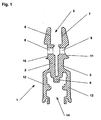
- Fig. 1 shows a profile device 1, which is provided for receiving a plate, for example a glass sheet of a wing.
- the profile device 1 which can be mounted in the edge region of the plate, can be used to connect fitting parts to the wing, for example, belts, roller carriages, locks, seals, etc.
- the profile device can also form a purely optical closure of the wing or edge protection for the plate ,
- the profile device 1 consists of a one-piece profile, which has two opposite clamping legs 2, 3 for receiving a plate and two likewise opposite connecting legs 12, 13 for connecting fitting parts.
- the clamping legs 2, 3 form with their opposite, respectively L-shaped inner surfaces 6, 7 a receiving groove 5 for the plate.
- the inner surfaces 6, 7 can be formed reibwerter bannd be. In the illustrated embodiment, they have a parallel to the longitudinal axis of the profile device 1 extending corrugation.
- the inner surfaces 6, 7 are slightly inclined to each other, so that their distance to the bottom of the receiving groove 5 is slightly increased.
- the connecting legs 12, 13 are integrally formed in the region of the web 4 to the clamping legs 2, 3, so that the connecting legs 12, 13 form with the web a receiving space 14 for fittings to be connected.
- the connecting legs 12, 13 have for this purpose grooves and projections on which the fittings to be connected can be fixed.
- the clamping legs 2, 3 have in the vicinity of the bottom of the receiving groove 5 mutually aligned pairs of holes formed as holes 8, 9.
- the profile of the clamping legs 2, 3 is provided to the outside with recesses 10, 11.
- the recess 10 of the one clamping leg 2 is formed in the form of a shallow groove, wherein the groove base is arranged perpendicular to the longitudinal axis of the opening 8.
- the shape of the recess 11 of the other clamping leg 3 corresponds in the embodiment in cross section a circle segment, but may also deviating, for example, the rectangular recess 10 of the first clamping leg 2, for example, be formed.
- the recesses 10, 11 must be located in the region of the openings 8, 9.
- the recesses 10, 11 extend over the entire length of the profile device 1.
- the pairs of openings 8, 9 may be arranged at certain intervals along the profile device 1. Alternatively, the openings 8, 9 can also be subsequently introduced manually to the respectively desired positions in the clamping legs 2, 3.
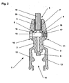
- Fig. 2 is the profile device 1 according to Fig. 1 shown with mounted plate 19.
- the plate 19 engages in the receiving groove 5 of the clamping legs 2, 3, wherein between the inner surfaces 6, 7 of the receiving groove 5 and the plate 19, an elastic intermediate layer 20 is arranged, which encloses the projecting into the receiving groove 5 edge region of the plate 19.
- the total thickness of the plate 19 with the Intermediate layer 20 is slightly smaller than the smallest distance of the inner surfaces 6, 7 in the edge region of the receiving groove. 5
- a further tightening of the screw 15 causes the clamping legs 2, 3 to move towards each other under flexurally elastic deformation. This reduces the distance of the inner surfaces 6, 7 of the receiving groove 5, so that the plate 19 is clamped under elastic deformation of the intermediate layer 20 in the receiving groove 5.
Landscapes
- Engineering & Computer Science (AREA)
- Civil Engineering (AREA)
- Structural Engineering (AREA)
- Securing Of Glass Panes Or The Like (AREA)
- Specific Sealing Or Ventilating Devices For Doors And Windows (AREA)
- Window Of Vehicle (AREA)
- Connection Of Plates (AREA)
Claims (8)
- Vantail, en particulier d'une fenêtre, d'une porte, ou d'une paroi, comprenant un système profilé (1) disposé dans la région du bord du vantail, pour recevoir un panneau (19) du vantail, le système profilé (1) présentant une rainure de réception (5), qui vient en prise autour de l'arête extérieure du panneau (19), et l'arête extérieure du panneau (19) pouvant être fixée par une connexion par serrage dans le système profilé (1), la largeur de la rainure de réception (5) pouvant être variée au moyen d'un système d'ajustement, et le système profilé (1), au moins dans la région de réception du panneau (19), étant réalisé sous la forme d'un profilé d'une seule pièce, et le profilé d'une seule pièce présentant deux branches de serrage (2, 3) opposées et une âme (4) reliant les branches de serrage (2, 3), qui permet de déplacer les branches de serrage (2, 3) de manière élastiquement flexible l'une par rapport à l'autre, et le système profilé (1) présentant une région de raccordement réalisée d'une seule pièce avec le système profilé (1) pour le raccordement de systèmes de ferrure, la région de raccordement présentant deux branches de raccordement opposées (12, 13) qui forment avec l'âme (4) un espace de réception (14) pour le raccordement des systèmes de ferrure,
caractérisé en ce que
les branches de raccordement (12, 13) présentent des formations appropriées pour le raccordement des systèmes de ferrure. - Vantail selon la revendication 1,
caractérisé en ce que les formations des branches de raccordement (12, 13), appropriées pour le raccordement des systèmes de ferrure, sont réalisées sous forme de nervures, saillies, rainures ou alésages. - Vantail selon la revendication 1,
caractérisé en ce que le système d'ajustement comprend au moins une vis (15) et au moins un écrou (18), la vis (15) venant en prise à travers des ouvertures (8, 9) disposées dans les branches de serrage (2, 3). - Vantail selon la revendication 3,
caractérisé en ce que la branche de serrage (2) s'appliquant contre la tête de vis (16) de la vis (15) présente sur son côté tourné vers l'extérieur, dans la région de l'ouverture (8), un évidement (10) pour la tête de vis (16). - Vantail selon la revendication 3,
caractérisé en ce que la branche de serrage (3) s'appliquant contre l'écrou (18) présente sur son côté tourné vers l'extérieur dans la région de l'ouverture (9), un évidement (11) pour l'écrou (18). - Vantail selon la revendication 5,
caractérisé en ce que l'écrou (18) est maintenu de manière non rotative dans l'évidement (11) de la branche de serrage (3), en étant formé de préférence complémentaire à l'évidement (11) de la branche de serrage (3). - Vantail selon la revendication 1,
caractérisé en ce que le système d'ajustement comprend au moins une vis (15), la vis (15) venant en prise à travers une ouverture (8) disposée dans l'une des branches de serrage (2) et pouvant être vissée dans le filetage interne d'une ouverture (9) disposée dans l'autre branche de serrage (3). - Vantail selon la revendication 1,
caractérisé en ce qu'au moins lorsque le panneau (19) est monté, les surfaces internes (6, 7) des branches de serrage (2, 3) sont disposées de manière inclinée l'une vers l'autre par rapport à la surface du vantail.
Priority Applications (1)
| Application Number | Priority Date | Filing Date | Title |
|---|---|---|---|
| PL04029415T PL1544403T3 (pl) | 2003-12-19 | 2004-12-13 | Skrzydło, zwłaszcza okna, drzwi lub ściany |
Applications Claiming Priority (2)
| Application Number | Priority Date | Filing Date | Title |
|---|---|---|---|
| DE10360589 | 2003-12-19 | ||
| DE10360589A DE10360589A1 (de) | 2003-12-19 | 2003-12-19 | Einteiliges Tragklemmprofil ohne Glasbohrung für MSW |
Publications (3)
| Publication Number | Publication Date |
|---|---|
| EP1544403A2 EP1544403A2 (fr) | 2005-06-22 |
| EP1544403A3 EP1544403A3 (fr) | 2006-10-04 |
| EP1544403B1 true EP1544403B1 (fr) | 2008-11-05 |
Family
ID=34485574
Family Applications (1)
| Application Number | Title | Priority Date | Filing Date |
|---|---|---|---|
| EP04029415A Revoked EP1544403B1 (fr) | 2003-12-19 | 2004-12-13 | Vantail, en particulier d'une fenêtre, porte ou paroi |
Country Status (6)
| Country | Link |
|---|---|
| EP (1) | EP1544403B1 (fr) |
| AT (1) | ATE413509T1 (fr) |
| DE (2) | DE10360589A1 (fr) |
| ES (1) | ES2312909T3 (fr) |
| PL (1) | PL1544403T3 (fr) |
| PT (1) | PT1544403E (fr) |
Cited By (1)
| Publication number | Priority date | Publication date | Assignee | Title |
|---|---|---|---|---|
| CN109898958A (zh) * | 2019-03-20 | 2019-06-18 | 安庆市博安工程有限责任公司 | 一种铝合金门窗及其组装方法 |
Families Citing this family (2)
| Publication number | Priority date | Publication date | Assignee | Title |
|---|---|---|---|---|
| DE102008030322A1 (de) | 2008-06-30 | 2009-12-31 | Geze Gmbh | Tragklemmprofil |
| DE102010037722A1 (de) * | 2010-09-23 | 2012-03-29 | Usines Claas France S.A.S. | Landwirtschaftliche Kolbenpresse |
Family Cites Families (8)
| Publication number | Priority date | Publication date | Assignee | Title |
|---|---|---|---|---|
| DE7200807U (de) * | 1972-04-06 | Schueco H Schuermann & Co | Ganzglas Türflügel | |
| CH430146A (de) * | 1965-04-22 | 1967-02-15 | Temperit Ag | Am unteren oberen Wand- oder Türrand befestigbare Leiste, insbesondere bei Türen oder Wänden aus Glas |
| EP0313672B1 (fr) * | 1984-02-13 | 1992-06-17 | SOCIETA' ITALIANA PROGETTI S.r.l. | Listeau de bord pour une vitre, en particulier pour un battant fait entièrement en verre |
| US4914888A (en) * | 1988-08-29 | 1990-04-10 | Capitol Glass & Aluminum Corporation | Support frame for glass panel |
| ES2092732T3 (es) | 1992-09-09 | 1996-12-01 | Karl Haab | Elemento de sujecion para sujetar de forma ajustable una placa en un elemento de marco, asi como elemento de pared. |
| DE29521069U1 (de) | 1995-06-23 | 1996-07-25 | Dorma Gmbh + Co. Kg, 58256 Ennepetal | Türschiene |
| DE29918539U1 (de) * | 1999-10-21 | 2000-04-06 | Cristalux Kirchberger Glas GmbH & Co., 55481 Kirchberg | Profil als Begrenzung für ein fächiges Gebilde |
| DE20319745U1 (de) * | 2003-11-28 | 2004-04-29 | Schulte Duschkabinenbau Gmbh & Co. Kg | Duschabtrennung und Halteprofil |
-
2003
- 2003-12-19 DE DE10360589A patent/DE10360589A1/de not_active Withdrawn
-
2004
- 2004-12-13 PL PL04029415T patent/PL1544403T3/pl unknown
- 2004-12-13 AT AT04029415T patent/ATE413509T1/de active
- 2004-12-13 PT PT04029415T patent/PT1544403E/pt unknown
- 2004-12-13 EP EP04029415A patent/EP1544403B1/fr not_active Revoked
- 2004-12-13 DE DE502004008399T patent/DE502004008399D1/de not_active Revoked
- 2004-12-13 ES ES04029415T patent/ES2312909T3/es not_active Expired - Lifetime
Cited By (2)
| Publication number | Priority date | Publication date | Assignee | Title |
|---|---|---|---|---|
| CN109898958A (zh) * | 2019-03-20 | 2019-06-18 | 安庆市博安工程有限责任公司 | 一种铝合金门窗及其组装方法 |
| CN109898958B (zh) * | 2019-03-20 | 2021-06-04 | 安徽博安门窗有限公司 | 一种铝合金门窗及其组装方法 |
Also Published As
| Publication number | Publication date |
|---|---|
| EP1544403A3 (fr) | 2006-10-04 |
| PL1544403T3 (pl) | 2009-04-30 |
| EP1544403A2 (fr) | 2005-06-22 |
| PT1544403E (pt) | 2008-11-20 |
| ES2312909T3 (es) | 2009-03-01 |
| ATE413509T1 (de) | 2008-11-15 |
| DE502004008399D1 (de) | 2008-12-18 |
| DE10360589A1 (de) | 2005-07-14 |
Similar Documents
| Publication | Publication Date | Title |
|---|---|---|
| EP1087147B1 (fr) | Dispositif de fixation pour éléments en plaques | |
| EP0841032A2 (fr) | Dispositif pour la fixation réglable des panneaux, en particulier panneaux de verre ou similaires | |
| EP1840315B2 (fr) | Construction de cadre | |
| AT511046A2 (de) | Rahmensystem eines partikelschutzgitters | |
| EP2927409B1 (fr) | Joint pour une porte coulissante | |
| EP2080862B1 (fr) | Ferrure de serrage | |
| EP1544403B1 (fr) | Vantail, en particulier d'une fenêtre, porte ou paroi | |
| WO2005035901A1 (fr) | Cadre d'etayage pour façade | |
| EP2084356B1 (fr) | Ensemble de ferrure pour portes, fenêtres ou analogues | |
| EP0539672B1 (fr) | Ferrure pour fixation dans une rainure d'un profilé rétréci des deux côtés | |
| EP3692611B1 (fr) | Dispositif de positionnement d'une piece plat sur un châssis d'armoire électrique et procédé correspondant | |
| EP2754803B1 (fr) | Crémone de fenêtre ou de porte et tringle pour une telle crémone | |
| EP0282809A2 (fr) | Système de ferrure pour la fixation respectivement pour le placement des plaques de verre sans cadres | |
| EP1256681B1 (fr) | Ferrure pour un élément de fermeture d'une ouverture dans un mur | |
| EP0468446A1 (fr) | Construction de façade constituée de montants et de traverses pour la fixation d'éléments plats | |
| DE4221506C2 (de) | Klemmvorrichtung zur Halterung von Glasscheiben | |
| EP1560996B1 (fr) | Systeme d'armatures pour portes en verre | |
| EP1127527A2 (fr) | Ferrure pour écran de douche avec joint d'étanchéité integré | |
| EP1186723B1 (fr) | Dispositif de fixation pour une façade avec montants et traverses | |
| DE102011008765A1 (de) | Profilanordnung, Rahmen und Rahmenanordnung | |
| EP2455574A2 (fr) | Cadre de fenêtre ou de porte | |
| DE20219264U1 (de) | Vorrichtung zum Verbinden des Befestigungsbereichs einer Führungsschiene mit dem Türboden einer Fahrzeugtür | |
| EP1469157B1 (fr) | Profil de verrouillage | |
| EP1783317B1 (fr) | Clip de fixation pour un profilé de support d'un dispositif d'occultation | |
| EP1344478B1 (fr) | Cabine de douche avec au moins une cloison de verre |
Legal Events
| Date | Code | Title | Description |
|---|---|---|---|
| PUAI | Public reference made under article 153(3) epc to a published international application that has entered the european phase |
Free format text: ORIGINAL CODE: 0009012 |
|
| AK | Designated contracting states |
Kind code of ref document: A2 Designated state(s): AT BE BG CH CY CZ DE DK EE ES FI FR GB GR HU IE IS IT LI LT LU MC NL PL PT RO SE SI SK TR |
|
| AX | Request for extension of the european patent |
Extension state: AL BA HR LV MK YU |
|
| PUAL | Search report despatched |
Free format text: ORIGINAL CODE: 0009013 |
|
| AK | Designated contracting states |
Kind code of ref document: A3 Designated state(s): AT BE BG CH CY CZ DE DK EE ES FI FR GB GR HU IE IS IT LI LT LU MC NL PL PT RO SE SI SK TR |
|
| AX | Request for extension of the european patent |
Extension state: AL BA HR LV MK YU |
|
| 17P | Request for examination filed |
Effective date: 20070403 |
|
| AKX | Designation fees paid |
Designated state(s): AT BE BG CH CY CZ DE DK EE ES FI FR GB GR HU IE IS IT LI LT LU MC NL PL PT RO SE SI SK TR |
|
| 17Q | First examination report despatched |
Effective date: 20071221 |
|
| GRAP | Despatch of communication of intention to grant a patent |
Free format text: ORIGINAL CODE: EPIDOSNIGR1 |
|
| GRAS | Grant fee paid |
Free format text: ORIGINAL CODE: EPIDOSNIGR3 |
|
| GRAA | (expected) grant |
Free format text: ORIGINAL CODE: 0009210 |
|
| AK | Designated contracting states |
Kind code of ref document: B1 Designated state(s): AT BE BG CH CY CZ DE DK EE ES FI FR GB GR HU IE IS IT LI LT LU MC NL PL PT RO SE SI SK TR |
|
| REG | Reference to a national code |
Ref country code: GB Ref legal event code: FG4D Free format text: NOT ENGLISH |
|
| REG | Reference to a national code |
Ref country code: CH Ref legal event code: NV Representative=s name: E. BLUM & CO. AG PATENT- UND MARKENANWAELTE VSP Ref country code: CH Ref legal event code: EP |
|
| REG | Reference to a national code |
Ref country code: PT Ref legal event code: SC4A Free format text: AVAILABILITY OF NATIONAL TRANSLATION Effective date: 20081107 |
|
| REG | Reference to a national code |
Ref country code: IE Ref legal event code: FG4D Free format text: LANGUAGE OF EP DOCUMENT: GERMAN |
|
| REF | Corresponds to: |
Ref document number: 502004008399 Country of ref document: DE Date of ref document: 20081218 Kind code of ref document: P |
|
| REG | Reference to a national code |
Ref country code: RO Ref legal event code: EPE |
|
| REG | Reference to a national code |
Ref country code: ES Ref legal event code: FG2A Ref document number: 2312909 Country of ref document: ES Kind code of ref document: T3 |
|
| REG | Reference to a national code |
Ref country code: GR Ref legal event code: EP Ref document number: 20090400305 Country of ref document: GR |
|
| LTIE | Lt: invalidation of european patent or patent extension |
Effective date: 20081105 |
|
| PG25 | Lapsed in a contracting state [announced via postgrant information from national office to epo] |
Ref country code: LT Free format text: LAPSE BECAUSE OF FAILURE TO SUBMIT A TRANSLATION OF THE DESCRIPTION OR TO PAY THE FEE WITHIN THE PRESCRIBED TIME-LIMIT Effective date: 20081105 |
|
| REG | Reference to a national code |
Ref country code: PL Ref legal event code: T3 |
|
| PG25 | Lapsed in a contracting state [announced via postgrant information from national office to epo] |
Ref country code: SI Free format text: LAPSE BECAUSE OF FAILURE TO SUBMIT A TRANSLATION OF THE DESCRIPTION OR TO PAY THE FEE WITHIN THE PRESCRIBED TIME-LIMIT Effective date: 20081105 Ref country code: IS Free format text: LAPSE BECAUSE OF FAILURE TO SUBMIT A TRANSLATION OF THE DESCRIPTION OR TO PAY THE FEE WITHIN THE PRESCRIBED TIME-LIMIT Effective date: 20090305 Ref country code: FI Free format text: LAPSE BECAUSE OF FAILURE TO SUBMIT A TRANSLATION OF THE DESCRIPTION OR TO PAY THE FEE WITHIN THE PRESCRIBED TIME-LIMIT Effective date: 20081105 |
|
| BERE | Be: lapsed |
Owner name: GEZE G.M.B.H. Effective date: 20081231 |
|
| PLBI | Opposition filed |
Free format text: ORIGINAL CODE: 0009260 |
|
| REG | Reference to a national code |
Ref country code: IE Ref legal event code: FD4D |
|
| PG25 | Lapsed in a contracting state [announced via postgrant information from national office to epo] |
Ref country code: BG Free format text: LAPSE BECAUSE OF FAILURE TO SUBMIT A TRANSLATION OF THE DESCRIPTION OR TO PAY THE FEE WITHIN THE PRESCRIBED TIME-LIMIT Effective date: 20090205 Ref country code: IE Free format text: LAPSE BECAUSE OF FAILURE TO SUBMIT A TRANSLATION OF THE DESCRIPTION OR TO PAY THE FEE WITHIN THE PRESCRIBED TIME-LIMIT Effective date: 20081105 Ref country code: EE Free format text: LAPSE BECAUSE OF FAILURE TO SUBMIT A TRANSLATION OF THE DESCRIPTION OR TO PAY THE FEE WITHIN THE PRESCRIBED TIME-LIMIT Effective date: 20081105 Ref country code: MC Free format text: LAPSE BECAUSE OF NON-PAYMENT OF DUE FEES Effective date: 20081231 Ref country code: DK Free format text: LAPSE BECAUSE OF FAILURE TO SUBMIT A TRANSLATION OF THE DESCRIPTION OR TO PAY THE FEE WITHIN THE PRESCRIBED TIME-LIMIT Effective date: 20081105 |
|
| 26 | Opposition filed |
Opponent name: DORMA GMBH + CO. KG Effective date: 20090702 |
|
| PG25 | Lapsed in a contracting state [announced via postgrant information from national office to epo] |
Ref country code: SE Free format text: LAPSE BECAUSE OF FAILURE TO SUBMIT A TRANSLATION OF THE DESCRIPTION OR TO PAY THE FEE WITHIN THE PRESCRIBED TIME-LIMIT Effective date: 20090205 Ref country code: CZ Free format text: LAPSE BECAUSE OF FAILURE TO SUBMIT A TRANSLATION OF THE DESCRIPTION OR TO PAY THE FEE WITHIN THE PRESCRIBED TIME-LIMIT Effective date: 20081105 |
|
| PLAX | Notice of opposition and request to file observation + time limit sent |
Free format text: ORIGINAL CODE: EPIDOSNOBS2 |
|
| PG25 | Lapsed in a contracting state [announced via postgrant information from national office to epo] |
Ref country code: BE Free format text: LAPSE BECAUSE OF NON-PAYMENT OF DUE FEES Effective date: 20081231 Ref country code: SK Free format text: LAPSE BECAUSE OF FAILURE TO SUBMIT A TRANSLATION OF THE DESCRIPTION OR TO PAY THE FEE WITHIN THE PRESCRIBED TIME-LIMIT Effective date: 20081105 |
|
| NLR1 | Nl: opposition has been filed with the epo |
Opponent name: DORMA GMBH + CO. KG |
|
| RDAF | Communication despatched that patent is revoked |
Free format text: ORIGINAL CODE: EPIDOSNREV1 |
|
| PGFP | Annual fee paid to national office [announced via postgrant information from national office to epo] |
Ref country code: AT Payment date: 20091217 Year of fee payment: 6 Ref country code: CH Payment date: 20091224 Year of fee payment: 6 Ref country code: ES Payment date: 20091222 Year of fee payment: 6 Ref country code: TR Payment date: 20091209 Year of fee payment: 6 |
|
| PGFP | Annual fee paid to national office [announced via postgrant information from national office to epo] |
Ref country code: PL Payment date: 20091125 Year of fee payment: 6 Ref country code: RO Payment date: 20091202 Year of fee payment: 6 Ref country code: NL Payment date: 20091222 Year of fee payment: 6 |
|
| PGFP | Annual fee paid to national office [announced via postgrant information from national office to epo] |
Ref country code: PT Payment date: 20091204 Year of fee payment: 6 |
|
| PGFP | Annual fee paid to national office [announced via postgrant information from national office to epo] |
Ref country code: FR Payment date: 20100108 Year of fee payment: 6 Ref country code: GB Payment date: 20091218 Year of fee payment: 6 Ref country code: IT Payment date: 20091221 Year of fee payment: 6 |
|
| RDAG | Patent revoked |
Free format text: ORIGINAL CODE: 0009271 |
|
| STAA | Information on the status of an ep patent application or granted ep patent |
Free format text: STATUS: PATENT REVOKED |
|
| REG | Reference to a national code |
Ref country code: CH Ref legal event code: PL |
|
| 27W | Patent revoked |
Effective date: 20100122 |
|
| REG | Reference to a national code |
Ref country code: PT Ref legal event code: MP4A Effective date: 20100615 |
|
| PGFP | Annual fee paid to national office [announced via postgrant information from national office to epo] |
Ref country code: DE Payment date: 20091231 Year of fee payment: 6 Ref country code: GR Payment date: 20091218 Year of fee payment: 6 |
|
| PG25 | Lapsed in a contracting state [announced via postgrant information from national office to epo] |
Ref country code: LU Free format text: LAPSE BECAUSE OF NON-PAYMENT OF DUE FEES Effective date: 20081213 Ref country code: CY Free format text: LAPSE BECAUSE OF FAILURE TO SUBMIT A TRANSLATION OF THE DESCRIPTION OR TO PAY THE FEE WITHIN THE PRESCRIBED TIME-LIMIT Effective date: 20081105 Ref country code: HU Free format text: LAPSE BECAUSE OF FAILURE TO SUBMIT A TRANSLATION OF THE DESCRIPTION OR TO PAY THE FEE WITHIN THE PRESCRIBED TIME-LIMIT Effective date: 20090506 |
|
| PG25 | Lapsed in a contracting state [announced via postgrant information from national office to epo] |
Ref country code: LI Free format text: LAPSE BECAUSE OF THE APPLICANT RENOUNCES Effective date: 20081105 Ref country code: CH Free format text: LAPSE BECAUSE OF THE APPLICANT RENOUNCES Effective date: 20081105 |