EP1542051A1 - Verfahren und Vorrichtung zum Trennen unterschiedlicher Emissionswellenlängen in einem Scanmikroskop - Google Patents
Verfahren und Vorrichtung zum Trennen unterschiedlicher Emissionswellenlängen in einem Scanmikroskop Download PDFInfo
- Publication number
- EP1542051A1 EP1542051A1 EP04022249A EP04022249A EP1542051A1 EP 1542051 A1 EP1542051 A1 EP 1542051A1 EP 04022249 A EP04022249 A EP 04022249A EP 04022249 A EP04022249 A EP 04022249A EP 1542051 A1 EP1542051 A1 EP 1542051A1
- Authority
- EP
- European Patent Office
- Prior art keywords
- excitation wavelengths
- light beam
- wavelengths
- sample
- excitation
- Prior art date
- Legal status (The legal status is an assumption and is not a legal conclusion. Google has not performed a legal analysis and makes no representation as to the accuracy of the status listed.)
- Granted
Links
- 238000000034 method Methods 0.000 title claims description 42
- 238000000926 separation method Methods 0.000 title description 3
- 230000005284 excitation Effects 0.000 claims abstract description 106
- 238000005286 illumination Methods 0.000 claims abstract description 47
- 238000012545 processing Methods 0.000 claims abstract description 4
- 230000004913 activation Effects 0.000 claims description 7
- 238000005259 measurement Methods 0.000 claims description 6
- 230000003252 repetitive effect Effects 0.000 claims description 6
- 239000000523 sample Substances 0.000 claims 13
- 238000001454 recorded image Methods 0.000 claims 1
- 238000010586 diagram Methods 0.000 description 9
- 230000009021 linear effect Effects 0.000 description 7
- 239000007850 fluorescent dye Substances 0.000 description 4
- 238000000799 fluorescence microscopy Methods 0.000 description 2
- 230000003595 spectral effect Effects 0.000 description 2
- 238000003491 array Methods 0.000 description 1
- 230000002457 bidirectional effect Effects 0.000 description 1
- 230000003851 biochemical process Effects 0.000 description 1
- 230000031018 biological processes and functions Effects 0.000 description 1
- 230000015572 biosynthetic process Effects 0.000 description 1
- 238000007796 conventional method Methods 0.000 description 1
- 230000008878 coupling Effects 0.000 description 1
- 238000010168 coupling process Methods 0.000 description 1
- 238000005859 coupling reaction Methods 0.000 description 1
- 230000001419 dependent effect Effects 0.000 description 1
- 238000013461 design Methods 0.000 description 1
- 238000001514 detection method Methods 0.000 description 1
- 238000011161 development Methods 0.000 description 1
- 230000018109 developmental process Effects 0.000 description 1
- 238000000295 emission spectrum Methods 0.000 description 1
- 238000002060 fluorescence correlation spectroscopy Methods 0.000 description 1
- 238000000386 microscopy Methods 0.000 description 1
- 230000003287 optical effect Effects 0.000 description 1
- 239000004065 semiconductor Substances 0.000 description 1
- 230000002123 temporal effect Effects 0.000 description 1
Images



Classifications
-
- G—PHYSICS
- G01—MEASURING; TESTING
- G01J—MEASUREMENT OF INTENSITY, VELOCITY, SPECTRAL CONTENT, POLARISATION, PHASE OR PULSE CHARACTERISTICS OF INFRARED, VISIBLE OR ULTRAVIOLET LIGHT; COLORIMETRY; RADIATION PYROMETRY
- G01J3/00—Spectrometry; Spectrophotometry; Monochromators; Measuring colours
- G01J3/28—Investigating the spectrum
- G01J3/44—Raman spectrometry; Scattering spectrometry ; Fluorescence spectrometry
- G01J3/4406—Fluorescence spectrometry
-
- G—PHYSICS
- G02—OPTICS
- G02B—OPTICAL ELEMENTS, SYSTEMS OR APPARATUS
- G02B21/00—Microscopes
- G02B21/16—Microscopes adapted for ultraviolet illumination ; Fluorescence microscopes
Definitions
- the present invention relates to a method and a device for separating different emission wavelengths in a scanning microscope, in which a Sample with a guided over the sample by means of a beam deflecting device Scanned illumination light beam, wherein the illumination light beam different Excitation wavelengths, and at which emanating from the sample Emission light corresponding to the excitation wavelengths Emission wavelengths detected in at least one detector.
- Sequential scan also causes problems with fast image changes, e.g. due to on a short time scale within the sample ongoing processes. When such fast processes occur, they result Differences in the individual pictures, since the pictures for different excitation wavelengths not be recorded at the same time. This is special critical in bidirectional line sequential scan, not even here there is a fixed time relation between the individual pixels. Will the won Image data processed by conventional methods, e.g. by Unfolding or linear unmixing, artifacts occur in the processed images on.
- the present invention is based on the object, a method and a Device for separating different emission wavelengths in one Scanning microscope of the type mentioned by simple means to design such and further educate that an increased recording speed for the Take separate images of a sample for several excitation wavelengths is achieved, so that in particular also fast running processes within the Sample can be reproduced without error.
- the inventive method for separating different emission wavelengths in a scanning microscope solves the above task by the Features of claim 1. Thereafter, such a method is characterized that the excitation wavelengths the illumination light beam during the scanning process according to a predetermined illumination scheme be switched on selectively, that the detector for each activation of an excitation wavelength is read out and that the detected signals the excitation wavelengths assigned using the known illumination scheme become.
- the excitation wavelengths the illumination light beam during the scanning process selectively switched according to a predefinable lighting scheme.
- the detector For each activation of an excitation wavelength, the detector becomes at least once read and based on the known lighting scheme the detected signals are assigned to the excitation waves.
- discrete could be as different excitation wavelengths Laser lines are used.
- the individual excitation wavelengths could be the illumination light beam then, for example, by simply turning on and off of the respective laser switch very easy.
- the sample could also have the intensity at which an excitation wavelength in the lighting scheme for each of the excitation wavelengths individually determined.
- every pixel of the image acquisition information from each of the excitation wavelengths could be the spatial progression the illumination light beam on the sample and the lighting scheme be coordinated with each other so that each of the excitation wavelengths the Illuminating light beam within a pixel of the image capture of the sample at least once switched on.
- these excitation wavelengths be switched on several times per pixel. Accordingly, that could Switching on certain excitation wavelengths for pixels that are "uninteresting" Sample areas correspond, even completely omitted.
- the lighting scheme is a regularly repeating sequence over the course of the scanning process the connection of the individual excitation wavelengths set.
- the lighting scheme are matched to one another such that a complete cycle of repetitive sequence with one pixel of image capture the sample corresponds. This ensures that the pixels of a particular Image of a specific excitation wavelength directly with each other are comparable since all pixel information results from the same irradiation. This applies to every single picture taken.
- the detected signals to the single excitation wavelengths could be the illumination light beam to each Time of scanning always only a single excitation wavelength be switched on.
- the illuminating light beam could at predetermined times also several, preferably two excitation wavelengths be switched on simultaneously. This measure could either at the same scanning speed the photon statistics are improved or at same photon statistics increase the speed of scanning.
- the reconstruction could the individual images of the sample by means of suitable multiplication, sum and / or Difference formation of the detected signals are performed.
- the release of a corresponding be necessary in a linear system of equations.
- To provide a maximum Information density in relation to the examined sample could be the one for the different Excitation wavelengths reconstructed images displayed in an overlay become.
- a photomultiplier for example, a photomultiplier, an APD (avalanche Photodiode), an MCP (Microchannel Plate Detector) or photodiode arrays at.
- Essential in this context is a sufficiently high speed of the detector, so that this for each turn on an excitation wavelength (at least once) can be read.
- the light intensity and / or the Time duration of the connection of an excitation wavelength over the time course of the Scanning be varied '.
- certain laser lines could in ROIs (Regions of Interest), i. in locally limited areas of the Sample, which are of special interest for some reason, stronger or weaker be switched on or be completely switched off.
- the variation of the light intensity and / or the duration of time could already occur a measurement.
- the variation could also be determined during a measurement and thus be actively responded to certain predetermined measurement data. Appears for example one of the emission wavelengths in the detected signals low intensity, so during the measuring process, the intensity of the corresponding Excitation wavelength can be increased or lowered in the opposite case become.
- a corresponding variation of light intensity and / or time duration could also be done with the help of decision-making criteria that by image processing from the extracted data of the current image or previous pictures were obtained.
- the above-mentioned object is achieved by the Characteristics of claim 19 solved.
- a device for separating different emission wavelengths in a scanning microscope thereby characterized in that the excitation wavelengths the illumination light beam during the scanning process according to a predefinable lighting scheme are selectively switchable, that the detector for each activation of an excitation wavelength is readable and that the detected signals the excitation wavelengths assignable using the known lighting scheme are.
- the device according to the invention serves to carry out a Method according to one of claims 1 to 16, so that to avoid Repetitions are referred to the previous part of the description.
- the activation of an excitation wavelength could be done by means of a AOTF (Acousto Optical Tunable Filter), an AOM (acousto-optic modulator), an EOM (electro-optical modulator), a mechanical shutter or by means of direct control of the laser done.
- a direct control of the laser is particularly advantageous in semiconductor lasers, since at these switching frequencies in the GHz range.
- the light intensity of the switched-on excitation wavelengths could be in conventional Via an adjustment unit by means of an attenuator, a filter, of an AOTF, an AOM, an EOM or the like. Furthermore The intensity could also exceed the duty cycle or the number of repetitions one cycle per pixel as described above be adjustable.
- the setting unit could be used for continuous adjustment the light intensity, for example in the form of an AOTF, with a digital Coupling circuit for connecting the individual excitation wavelengths.
- a computing unit for temporal allocation the connection of an excitation wavelength and the readout of the detector be provided.
- the arithmetic unit could also be the assignment of the detected Control signals to the different excitation wavelengths.
- the arithmetic unit For example, it could be a CPU, a DSP, act an FPGA or a driver board.
- Fig. 1 shows two diagrams, in the upper diagram, the illumination intensity the sample 4 is shown in the time course of the scanning process.
- the sample 4 is with a total of three excitation wavelengths 1, 2, 3 corresponding to a predetermined Lighting schemes irradiated.
- a lighting scheme is chosen which is one over the course of the scanning process regularly recurring sequence of switched-on excitation wavelengths 1, 2, 3 shows.
- the repetitive sequence is like this each selected one cycle of the sequence with a pixel of later image acquisition corresponds.
- the bottom diagram shows the time over the scanning process detected intensity of the corresponding to the excitation wavelengths 1, 2, 3 corresponding Emission wavelengths.
- the detector 5 is for each activated excitation wavelength 1, 2, 3 read separately.
- the readout of the detector 5 is in symbolized by the dark dots.
- the detected signals According to the invention using the known lighting scheme associated with the excitation wavelengths 1, 2, 3. As in the lower diagram can be clearly seen, in this way for each of the excitation wavelengths 1, 2, 3 a separate picture are composed pixel by pixel.
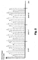
- FIG. 2 also shows diagrammatically a lighting scheme similar to that in FIG Fig. 1.
- the sample 4 in turn is over the time course of the scanning process regularly repeating sequence of the three excitation wavelengths 1, 2, 3 steals.
- the only difference from the embodiment in FIG. 1 is that the connection of the individual excitation wavelengths 1, 2, 3 such that a total of three complete cycles of repetitive Sequence one pixel of the image recording of the sample 4 correspond.
- the sample 4 becomes the illuminates a more uniform and can on the other hand per pixel a higher Quantum statistics for each of the excitation wavelengths 1, 2, 3 achieve.
- the illumination intensity is again dependent on the upper diagram represented by the time course of the scanning process.
- the sample 4 in this embodiment partly with two different excitation wavelengths 1, 2, 3 illuminated at the same time. Specifically, the sample 4 is first combined the two excitation wavelengths 1 and 2 irradiated. This is followed by a Lighting with both excitation wavelengths 2 and 3 on, and finally becomes illuminated exclusively with the excitation wavelength 3. This sequence repeats itself regularly, again a complete cycle with a pixel of the Picture recording corresponds.
- the lower diagram again shows the intensity detected as a function of time History of the scanning shown.
- Each of the dark spots features the reading of the detector 5.
- the detected signals are initially presorted.
- the obtained during the illumination with the excitation wavelengths 1 and 2 Signals are grouped into raw data for image 1, which is used for lighting obtained with the excitation wavelengths 2 and 3 signals to raw data for image 2 and finally recorded during illumination with excitation wavelength 3 Signals to raw data for Figure 3 summarized.
- the final pictures for the individual excitation wavelengths 1, 2, 3 can then be by suitable Generate multiplication, sum and difference of the raw data.
- the image for excitation wavelength 2 in simple way by pixelwise subtraction of the raw data from image 3 of the Generate raw data for picture 2.
- the image acquisition would then be possible for excitation wavelength 1 reconstruct.
- a corresponding linear system of equations are solved.
- Fig. 4 shows schematically an embodiment of a device according to the invention for separating different emission wavelengths in a scanning microscope 6.
- the device comprises an AOTF 7 operated in such a way that 9 specific wavelengths hidden from the light beam 8 a light source and specifiable excitation wavelengths 1, 2, 3 are transmitted. With others Words, the AOTF 7 is used to the illumination light beam 10 in a timely manner specifiable excitation wavelengths 1, 2, 3 switch on.
- the so constructed Illuminating light beam 10 is coupled into the microscope 6 and by means of a arranged in the microscope 6 beam deflecting device on the sample. 4 guided.
- the signals received by the detector 5 become a central processing unit 11, which shows the time allocation between the connection the individual excitation wavelengths 1, 2, 3 and the detection controls.
- the central Processor unit 11 is also for the assignment of the detected signals to the different excitation wavelengths 1, 2, 3 responsible.
- the individual Excitation wavelengths 1, 2, 3 associated data are in separate data channels 12, 13, 14, and finally for each of the excitation wavelengths 1, 2, 3 to generate a separate image of the sample 4.
- Fig. 5 shows in a schematic representation substantially the device from Fig. 4 with an additional unit 15, with a linear Unmixing for improved Separation of the different fluorescent dyes 16, 17, 18 in the Sample 4 is possible.
- Unmixing is well known from the literature, and will not be described here. Only as an example this point to DE 199 15 137 C2 and to US 6,066,459.
Landscapes
- Physics & Mathematics (AREA)
- Spectroscopy & Molecular Physics (AREA)
- General Physics & Mathematics (AREA)
- Chemical & Material Sciences (AREA)
- Analytical Chemistry (AREA)
- Optics & Photonics (AREA)
- Microscoopes, Condenser (AREA)
- Investigating, Analyzing Materials By Fluorescence Or Luminescence (AREA)
Abstract
Description
- Fig. 1
- in Form eines Diagramms ein erstes Ausführungsbeispiel eines Beleuchtungsschemas eines erfindungsgemäßen Verfahrens zum Trennen unterschiedlicher Emissionswellenlängen in einem Scanmikroskop,
- Fig. 2
- in Form eines Diagramms ein zweites Ausführungsbeispiel eines Beleuchtungsschemas eines erfindungsgemäßen Verfahrens,
- Fig. 3
- ebenfalls in Diagrammform ein drittes Ausführungsbeispiel eines Beleuchtungsschemas eines erfindungsgemäßen Verfahrens,
- Fig. 4
- in schematischer Darstellung ein Ausführungsbeispiel einer erfindungsgemäßen Vorrichtung zum Trennen unterschiedlicher Emissionswellenlängen in einem Scanmikroskop und
- Fig. 5
- in schematischer Darstellung die Vorrichtung aus Fig. 4 mit einer zusätzlichen Einheit für Lineares Unmixing.
Claims (13)
- Verfahren zum Trennen unterschiedlicher Emissionswellenlängen in einem Scanmikroskop (6), bei dem eine Probe (4) mit einem mittels einer Strahlablenkeinrichtung über die Probe (4) geführten Beleuchtungslichtstrahl (10) abgetastet wird, wobei der Beleuchtungslichtstrahl (10) unterschiedliche Anregungswellenlängen (1, 2, 3) aufweist, und bei dem das von der Probe (4) ausgehende Emissionslicht, das mit den Anregungswellenlängen (1, 2, 3) korrespondierende Emissionswellenlängen enthält, in mindestens einem Detektor (5) nachgewiesen wird,
dadurch gekennzeichnet, dass die Anregungswellenlängen (1, 2, 3) dem Beleuchtungslichtstrahl (10) während des Abtastvorgangs entsprechend eines vorgebbaren Beleuchtungsschemas selektiv zugeschaltet werden, dass der Detektor (5) für jedes Zuschalten einer Anregungswellenlänge (1, 2, 3) ausgelesen wird und dass die detektierten Signale den Anregungswellenlängen (1, 2, 3) unter Ausnutzung des bekannten Beleuchtungsschemas zugeordnet werden. - Verfahren nach Anspruch 1, dadurch gekennzeichnet, dass als unterschiedliche Anregungswellenlängen (1, 2, 3) diskrete Laserlinien verwendet werden, wobei die Anregungswellenlängen (1, 2, 3) dem Beleuchtungslichtstrahl (10) vorzugsweise durch An- und Ausschalten des jeweiligen Lasers zugeschaltet werden.
- Verfahren nach Anspruch 1 oder 2, dadurch gekennzeichnet, dass mit dem Beleuchtungsschema der Zeitpunkt und die Zeitdauer des Zuschaltens jeder der Anregungswellenlängen (1, 2, 3) festgelegt wird und/oder dass mit dem Beleuchtungsschema die Intensität für jede der Anregungswellenlängen (1, 2, 3) individuell festgelegt wird.
- Verfahren nach einem der Ansprüche 1 bis 3, dadurch gekennzeichnet, dass das räumliche Fortschreiten des Beleuchtungslichtstrahls (10) auf der Probe (4) und das Beleuchtungsschema derart aufeinander abgestimmt werden, dass jede der Anregungswellenlängen (1, 2, 3) dem Beleuchtungslichtstrahl (10) innerhalb eines Pixels der Bildaufnahme der Probe (4) mindestens einmal zugeschaltet ist.
- Verfahren nach einem der Ansprüche 1 bis 4, dadurch gekennzeichnet, dass mit dem Beleuchtungsschema eine sich über den Zeitverlauf des Abtastvorgangs hinweg regelmäßig wiederholende Abfolge des Zuschaltens der einzelnen Anregungswellenlängen (1, 2, 3) festgelegt wird, wobei das räumliche Fortschreiten des Beleuchtungslichtstrahls (10) auf der Probe (4) und das Beleuchtungsschema derart aufeinander abgestimmt werden können, dass ein kompletter Zyklus der sich wiederholende Abfolge mit einem Pixel der Bildaufnahme der Probe (4) korrespondiert, oder wobei das räumliche Fortschreiten des Beleuchtungslichtstrahls (10) auf der Probe (4) und das Beleuchtungsschema derart aufeinander abgestimmt werden können, dass mehrere, vorzugsweise zwei oder drei Zyklen der sich wiederholende Abfolge mit einem Pixel der Bildaufnahme der Probe (4) korrespondieren.
- Verfahren nach einem der Ansprüche 1 bis 5, dadurch gekennzeichnet, dass dem Beleuchtungslichtstrahl (10) jeweils immer nur eine einzige Anregungswellenlänge (1, 2, 3) zugeschaltet wird.
- Verfahren nach Anspruch 5 oder 6, dadurch gekennzeichnet, dass dem Beleuchtungslichtstrahl (10) innerhalb eines Zyklus zu vorgebbaren Zeitpunkten mehrere, vorzugsweise zwei Anregungswellenlängen (1, 2, 3) gleichzeitig zugeschaltet werden.
- Verfahren nach einem der Ansprüche 1 bis 7, dadurch gekennzeichnet, dass die Rekonstruktion der einzelnen Bilder der Probe (4) mittels geeigneter Multiplikation, Summen- und/oder Differenzbildung der detektierten Signale durchgeführt wird, wobei die für verschiedene Anregungswellenlängen (1, 2, 3) rekonstruierten Bilder vorzugsweise in einem Overlay angezeigt werden.
- Verfahren nach einem der Ansprüche 1 bis 8, dadurch gekennzeichnet, dass als Detektor (5) ein Photomultiplier, eine APD, ein MCP-Detektor, ein schnelles Photodiodenarray oder dergleichen eingesetzt werden und/oder dass die Lichtintensität und/oder die Zeitdauer des Zuschaltens einer Anregungswellenlänge (1, 2, 3) über den Zeitverlauf des Abtastvorgangs hinweg variiert werden, wobei die Variation der Lichtintensität und/oder der Zeitdauer vorzugsweise vor einer Messung oder in Abhängigkeit bestimmter vorgebbarer Messdaten vorzugsweise automatisch während einer Messung oder in Abhängigkeit von durch Bildverarbeitung aus den extrahierten Daten des momentanen Bildes und/oder vorhergehend aufgenommener Bilder gewonnenen Informationen festgelegt wird.
- Vorrichtung zum Trennen unterschiedlicher Emissionswellenlängen in einem Scanmikroskop (6), mit mindestens einer Lichtquelle (9) zur Erzeugung eines Beleuchtungslichtstrahls (10) mit unterschiedlichen Anregungswellenlängen (1, 2, 3), wobei eine Probe (4) mit dem mittels einer Strahlablenkeinrichtung über die Probe (4) geführten Beleuchtungslichtstrahl (10) abtastbar ist, und mit mindestens einem Detektor (5) zum Nachweis des von der Probe (4) ausgehenden Emissionslichts, das mit den Anregungswellenlängen (1, 2, 3) korrespondierende Emissionswellenlängen enthält, insbesondere zur Durchführung des Verfahrens nach einem der Ansprüche 1 bis 9,
dadurch gekennzeichnet, dass die Anregungswellenlängen (1, 2, 3) dem Beleuchtungslichtstrahl (10) während des Abtastvorgangs entsprechend eines vorgebbaren Beleuchtungsschemas selektiv zuschaltbar sind, dass der Detektor (5) für jedes Zuschalten einer Anregungswellenlänge (1, 2, 3) auslesbar ist und dass die detektierten Signale den Anregungswellenlängen (1, 2, 3) unter Ausnutzung des bekannten Beleuchtungsschemas zuordenbar sind. - Vorrichtung nach Anspruch 10, dadurch gekennzeichnet, dass das Zuschalten einer Anregungswellenlänge (1, 2, 3) mittels eines AOTF (7), eines AOM, eines EOM, eines mechanischen Shutters oder mittels direkter Ansteuerung eines Lasers erfolgt und/oder dass die Lichtintensität der zugeschalteten Anregungswellenlängen (1, 2, 3) mittels eines Abschwächers, eines Filters, eines AOTF (7), eines AOM, eines EOM oder dergleichen einstellbar ist, wobei der AOTF (7) zur kontinuierlichen Einstellung der Lichtintensität mit einer digitalen Schaltung zum Zuschalten der Anregungswellenlängen (1, 2, 3) gekoppelt sein kann.
- Vorrichtung nach Anspruch 10 oder 11, dadurch gekennzeichnet, dass eine Recheneinheit (11) zur zeitlichen Zuordnung des Zuschaltens einer Anregungswellenlänge (1, 2, 3) und dem Auslesen des Detektors (5) vorgesehen ist, wobei die Recheneinheit (11) die Zuordnung der detektierten Signale zu den unterschiedlichen Anregungswellenlängen (1, 2, 3) steuern kann und eine CPU, ein DSP, ein FPGA, ein Treiberboard oder dergleichen sein kann.
- Vorrichtung nach einem der Ansprüche 10 bis 12, dadurch gekennzeichnet, dass der Detektor (5) ein Photomultiplier, eine APD, ein MCP-Detektor, ein schnelles Photodiodenarray oder dergleichen ist.
Applications Claiming Priority (2)
| Application Number | Priority Date | Filing Date | Title |
|---|---|---|---|
| DE10357584A DE10357584B4 (de) | 2003-12-08 | 2003-12-08 | Verfahren zum Trennen unterschiedlicher Emissionswellenlängen in einem Scanmikroskop |
| DE10357584 | 2003-12-08 |
Publications (2)
| Publication Number | Publication Date |
|---|---|
| EP1542051A1 true EP1542051A1 (de) | 2005-06-15 |
| EP1542051B1 EP1542051B1 (de) | 2007-07-18 |
Family
ID=34485278
Family Applications (1)
| Application Number | Title | Priority Date | Filing Date |
|---|---|---|---|
| EP04022249A Expired - Lifetime EP1542051B1 (de) | 2003-12-08 | 2004-09-17 | Verfahren und Vorrichtung zum Trennen unterschiedlicher Emissionswellenlängen in einem Scanmikroskop |
Country Status (4)
| Country | Link |
|---|---|
| US (1) | US7038193B2 (de) |
| EP (1) | EP1542051B1 (de) |
| JP (1) | JP4798990B2 (de) |
| DE (2) | DE10357584B4 (de) |
Cited By (1)
| Publication number | Priority date | Publication date | Assignee | Title |
|---|---|---|---|---|
| US7038193B2 (en) | 2003-12-08 | 2006-05-02 | Leica Microsystems Heidelberg Gmbh | Method and device for separating different emission wavelengths in a scanning microscope |
Families Citing this family (14)
| Publication number | Priority date | Publication date | Assignee | Title |
|---|---|---|---|---|
| EP1942334A4 (de) * | 2005-09-28 | 2011-01-12 | Olympus Corp | Fluoreszenzspektralanalysegerät |
| US8101426B2 (en) * | 2007-03-02 | 2012-01-24 | Icyt Mission Technology, Inc. | System and method for the measurement of multiple fluorescence emissions in a flow cytometry system |
| GB0800936D0 (en) | 2008-01-19 | 2008-02-27 | Fianium Ltd | A source of optical supercontinuum generation having a selectable pulse repetition frequency |
| DE102010015915A1 (de) * | 2010-03-11 | 2011-09-15 | Leica Microsystems Cms Gmbh | Verfahren für einen beschleunigten Anregungswellenlängen-Scan bei einem Fluoreszenzmikroskop |
| CN101916428A (zh) * | 2010-08-18 | 2010-12-15 | 中国科学院光电技术研究所 | 一种图像数据的图像处理装置 |
| WO2014110290A1 (en) | 2013-01-09 | 2014-07-17 | The Regents Of The University Of California | Apparatus and methods for fluorescence imaging using radiofrequency-multiplexed excitation |
| WO2015143041A1 (en) | 2014-03-18 | 2015-09-24 | The Regents Of The University Of California | Parallel flow cytometer using radiofrequency mulitplexing |
| EP3362778B1 (de) | 2015-10-13 | 2022-08-03 | Omega Biosystems Incorporated | Multimodales fluoreszenzbildgebungs-durchflusszytometriesystem |
| CA3018065A1 (en) | 2016-03-17 | 2017-09-21 | Bd Biosciences | Cell sorting using a high throughput fluorescence flow cytometer |
| JP7023244B2 (ja) | 2016-05-12 | 2022-02-21 | ビーディー バイオサイエンス | 画像解像度が改良された蛍光イメージングフローサイトメトリー |
| US10006852B2 (en) | 2016-09-13 | 2018-06-26 | Becton, Dickinson And Company | Flow cytometer with optical equalization |
| WO2021007075A1 (en) | 2019-07-10 | 2021-01-14 | Becton, Dickinson And Company | Reconfigurable integrated circuits for adjusting cell sorting classification |
| JP7867444B2 (ja) | 2020-05-19 | 2026-05-29 | ベクトン・ディキンソン・アンド・カンパニー | レーザービームの強度プロファイルを変調するための方法及びそのシステム |
| WO2021262285A1 (en) | 2020-06-26 | 2021-12-30 | Becton, Dickinson And Company | Dual excitation beams for irradiating a sample in a flow stream and methods for using same |
Citations (2)
| Publication number | Priority date | Publication date | Assignee | Title |
|---|---|---|---|---|
| JPH01282515A (ja) * | 1988-05-10 | 1989-11-14 | Tokyo Electron Ltd | ビーム走査型光学顕微鏡 |
| DE19702753A1 (de) * | 1997-01-27 | 1998-07-30 | Zeiss Carl Jena Gmbh | Laser-Scanning-Mikroskop |
Family Cites Families (19)
| Publication number | Priority date | Publication date | Assignee | Title |
|---|---|---|---|---|
| DE260342C (de) | ||||
| DE3610165A1 (de) * | 1985-03-27 | 1986-10-02 | Olympus Optical Co., Ltd., Tokio/Tokyo | Optisches abtastmikroskop |
| JPS62237862A (ja) * | 1986-04-09 | 1987-10-17 | Kowa Co | レ−ザ−光走査装置 |
| DD260342A1 (de) * | 1987-05-04 | 1988-09-21 | Zeiss Jena Veb Carl | Verfahren und anordnung zur erzeugung von echtfarbenbildern mikroskopischer objekte |
| US5817462A (en) * | 1995-02-21 | 1998-10-06 | Applied Spectral Imaging | Method for simultaneous detection of multiple fluorophores for in situ hybridization and multicolor chromosome painting and banding |
| JP2590297Y2 (ja) * | 1991-03-15 | 1999-02-10 | オリンパス光学工業株式会社 | 光源装置 |
| DE4115401C2 (de) * | 1991-05-10 | 1994-04-14 | Rainer Dr Uhl | Fluoreszenz-Meßvorrichtung zum Bestimmen der Ionenkonzentration eines Untersuchungsobjekts, das mit einem Fluoreszenzfarbstoff eingefärbt ist, dessen Anregungsmaximum sich in Abhängigkeit von der zu bestimmenden Ionenkonzentration ändert |
| JPH10206745A (ja) * | 1997-01-22 | 1998-08-07 | Olympus Optical Co Ltd | 走査型光学顕微鏡 |
| DE19829981C2 (de) * | 1998-07-04 | 2002-10-17 | Zeiss Carl Jena Gmbh | Verfahren und Anordnung zur konfokalen Mikroskopie |
| US6337472B1 (en) * | 1998-10-19 | 2002-01-08 | The University Of Texas System Board Of Regents | Light imaging microscope having spatially resolved images |
| DE19915137C2 (de) * | 1999-03-26 | 2001-10-18 | Michael Schaefer | Verfahren zur Quantifizierung mehrerer Fluorochrome in einer mehrfach gefärbten Probe bei der Fluoreszenzmikroskopie und Verwendungen des Verfahrens |
| JP2001356272A (ja) * | 2000-06-12 | 2001-12-26 | Olympus Optical Co Ltd | 画像取得方法及び走査型光学顕微鏡 |
| DE10054426B4 (de) | 2000-10-27 | 2006-03-09 | Iom Innovative Optische Messtechnik Gmbh | Verfahren zur Multi-Fluoreszenz-Detektion |
| JP4896301B2 (ja) * | 2001-03-22 | 2012-03-14 | オリンパス株式会社 | 走査型光学顕微鏡 |
| DE10210737A1 (de) * | 2001-08-28 | 2003-03-20 | Gnothis Holding Sa Ecublens | Einkanal-Mehrfarben-Korrelationsanalyse |
| EP1421367A1 (de) | 2001-08-28 | 2004-05-26 | Gnothis Holding SA | Einkanal-mehrfarben-korrelationsanalyse |
| JP2003121748A (ja) * | 2001-10-16 | 2003-04-23 | Koike Seiki Kk | カラーレーザー走査型顕微鏡 |
| DE10225838B4 (de) * | 2002-06-11 | 2021-10-21 | Leica Microsystems Cms Gmbh | Verfahren zur Scanmikroskopie, Scanmikroskop und Vorrichtung zum Codieren eines Beleuchtungslichtstrahles |
| DE10357584B4 (de) | 2003-12-08 | 2006-06-14 | Leica Microsystems Cms Gmbh | Verfahren zum Trennen unterschiedlicher Emissionswellenlängen in einem Scanmikroskop |
-
2003
- 2003-12-08 DE DE10357584A patent/DE10357584B4/de not_active Expired - Fee Related
- 2003-12-22 US US10/744,205 patent/US7038193B2/en not_active Expired - Lifetime
-
2004
- 2004-09-17 DE DE502004004346T patent/DE502004004346D1/de not_active Expired - Lifetime
- 2004-09-17 EP EP04022249A patent/EP1542051B1/de not_active Expired - Lifetime
- 2004-12-07 JP JP2004354160A patent/JP4798990B2/ja not_active Expired - Fee Related
Patent Citations (2)
| Publication number | Priority date | Publication date | Assignee | Title |
|---|---|---|---|---|
| JPH01282515A (ja) * | 1988-05-10 | 1989-11-14 | Tokyo Electron Ltd | ビーム走査型光学顕微鏡 |
| DE19702753A1 (de) * | 1997-01-27 | 1998-07-30 | Zeiss Carl Jena Gmbh | Laser-Scanning-Mikroskop |
Non-Patent Citations (1)
| Title |
|---|
| PATENT ABSTRACTS OF JAPAN vol. 014, no. 059 (P - 1000) 2 February 1990 (1990-02-02) * |
Cited By (1)
| Publication number | Priority date | Publication date | Assignee | Title |
|---|---|---|---|---|
| US7038193B2 (en) | 2003-12-08 | 2006-05-02 | Leica Microsystems Heidelberg Gmbh | Method and device for separating different emission wavelengths in a scanning microscope |
Also Published As
| Publication number | Publication date |
|---|---|
| DE10357584B4 (de) | 2006-06-14 |
| DE10357584A1 (de) | 2005-07-07 |
| JP2005173604A (ja) | 2005-06-30 |
| US20050121603A1 (en) | 2005-06-09 |
| US7038193B2 (en) | 2006-05-02 |
| JP4798990B2 (ja) | 2011-10-19 |
| EP1542051B1 (de) | 2007-07-18 |
| DE502004004346D1 (de) | 2007-08-30 |
Similar Documents
| Publication | Publication Date | Title |
|---|---|---|
| DE69116126T2 (de) | Bildgebender Durchflusszytometer | |
| DE69319528T2 (de) | Konfokales Rastermikroskop mit kontinuierlicher Anzeige | |
| DE19829944C2 (de) | Verfahren und Anordnung zur Gerätekonfiguration eines Fluoreszenz-Laserscanmikroskops | |
| EP1542051B1 (de) | Verfahren und Vorrichtung zum Trennen unterschiedlicher Emissionswellenlängen in einem Scanmikroskop | |
| EP2156235B1 (de) | Mikroskop und verfahren zum betreiben eines mikroskops | |
| DE102008018476B4 (de) | Mikroskopievorrichtung | |
| DE102017223102A1 (de) | Multipuls-Lidarsystem zur mehrdimensionalen Erfassung von Objekten | |
| DE10038526B4 (de) | Verfahren und Anordnung zur Erfassung des wellenlängenabhängigen Verhaltens einer beleuchteten Probe | |
| EP1034443A1 (de) | Vorrichtung zum auslesen von einer in einem phosphorträger abgespeicherten information und röntgenkassette | |
| DE10225838A1 (de) | Verfahren zur Scanmikroskopie, Scanmikroskop und Vorrichtung zum Codieren eines Beleuchtungslichtstrahles | |
| DE10151216A1 (de) | Verfahren zur optischen Erfassung von charakteristischen Größen einer beleuchteten Probe | |
| DE2437984B2 (de) | Verfahren zur kontrastverbesserung eines optischen mikroskopes | |
| DE60205064T2 (de) | Vorrichtung und Verfahren für ROI-Abtastung mit hoher zeitlicher Auflösung | |
| DE102023100926A1 (de) | Mikroskop | |
| EP3271694A1 (de) | Lichtemissionsmessgerät und verfahren zur messung von lichtemission | |
| DE102010007730B4 (de) | Verfahren und Vorrichtung zum Einstellen eines geeigneten Auswerteparameters für ein Fluoreszenzmikroskop | |
| DE10339312A1 (de) | Verfahren zur Trennung von Fluoreszenzspektren von in einer Probe vorhandenen Farbstoffen | |
| DE2450112C3 (de) | Verfahren und Anordnung zur zerstörungsfreien Analyse biologischer Zeilen einer mindestens zwei unterschiedliche, licht bekannter Wellenlänge unterschiedlich stark absorbierende Zellentypen in zueinander festgelegter Lage enthaltenden Probe | |
| EP1691217A1 (de) | Auslesevorrichtung und Verfahren zum Auslesen von in Speicherleuchtstoffschichten gespeicherten Röntgenaufnahmen | |
| DE102011000090B4 (de) | Verfahren und Einrichtung zur rastermikroskopischen Abbildung eines Objektes | |
| EP1929353B1 (de) | Verfahren zur erzeugung von darstellungsbildern aus erfassten aufnahmebildern und mittel zur durchführung des verfahrens | |
| DE10355150A1 (de) | Verfahren und System zur Analyse von Co-Lokalisationen | |
| EP1177426A1 (de) | Mikroskopsysteme zur optischen abtastung von mikroskopischen objekten | |
| DE102006009830A1 (de) | Verfahren zur räumlich hochauflösenden Untersuchung von Proben | |
| DE102014108044A1 (de) | Lichtmikroskop mit einer rotierbaren Scheibe und Verfahren zum Mikroskopieren mit diesem |
Legal Events
| Date | Code | Title | Description |
|---|---|---|---|
| PUAI | Public reference made under article 153(3) epc to a published international application that has entered the european phase |
Free format text: ORIGINAL CODE: 0009012 |
|
| AK | Designated contracting states |
Kind code of ref document: A1 Designated state(s): AT BE BG CH CY CZ DE DK EE ES FI FR GB GR HU IE IT LI LU MC NL PL PT RO SE SI SK TR |
|
| AX | Request for extension of the european patent |
Extension state: AL HR LT LV MK |
|
| 17P | Request for examination filed |
Effective date: 20050928 |
|
| AKX | Designation fees paid |
Designated state(s): DE FR GB |
|
| RAP1 | Party data changed (applicant data changed or rights of an application transferred) |
Owner name: LEICA MICROSYSTEMS CMS GMBH |
|
| GRAP | Despatch of communication of intention to grant a patent |
Free format text: ORIGINAL CODE: EPIDOSNIGR1 |
|
| GRAS | Grant fee paid |
Free format text: ORIGINAL CODE: EPIDOSNIGR3 |
|
| GRAA | (expected) grant |
Free format text: ORIGINAL CODE: 0009210 |
|
| AK | Designated contracting states |
Kind code of ref document: B1 Designated state(s): DE FR GB |
|
| REG | Reference to a national code |
Ref country code: GB Ref legal event code: FG4D Free format text: NOT ENGLISH |
|
| REF | Corresponds to: |
Ref document number: 502004004346 Country of ref document: DE Date of ref document: 20070830 Kind code of ref document: P |
|
| GBT | Gb: translation of ep patent filed (gb section 77(6)(a)/1977) |
Effective date: 20071024 |
|
| ET | Fr: translation filed | ||
| PLBE | No opposition filed within time limit |
Free format text: ORIGINAL CODE: 0009261 |
|
| STAA | Information on the status of an ep patent application or granted ep patent |
Free format text: STATUS: NO OPPOSITION FILED WITHIN TIME LIMIT |
|
| 26N | No opposition filed |
Effective date: 20080421 |
|
| REG | Reference to a national code |
Ref country code: FR Ref legal event code: PLFP Year of fee payment: 12 |
|
| REG | Reference to a national code |
Ref country code: FR Ref legal event code: PLFP Year of fee payment: 13 |
|
| REG | Reference to a national code |
Ref country code: FR Ref legal event code: PLFP Year of fee payment: 14 |
|
| REG | Reference to a national code |
Ref country code: FR Ref legal event code: PLFP Year of fee payment: 15 |
|
| PGFP | Annual fee paid to national office [announced via postgrant information from national office to epo] |
Ref country code: FR Payment date: 20180928 Year of fee payment: 15 |
|
| PGFP | Annual fee paid to national office [announced via postgrant information from national office to epo] |
Ref country code: GB Payment date: 20180928 Year of fee payment: 15 |
|
| PGFP | Annual fee paid to national office [announced via postgrant information from national office to epo] |
Ref country code: DE Payment date: 20181130 Year of fee payment: 15 |
|
| REG | Reference to a national code |
Ref country code: DE Ref legal event code: R119 Ref document number: 502004004346 Country of ref document: DE |
|
| PG25 | Lapsed in a contracting state [announced via postgrant information from national office to epo] |
Ref country code: DE Free format text: LAPSE BECAUSE OF NON-PAYMENT OF DUE FEES Effective date: 20200401 |
|
| GBPC | Gb: european patent ceased through non-payment of renewal fee |
Effective date: 20190917 |
|
| PG25 | Lapsed in a contracting state [announced via postgrant information from national office to epo] |
Ref country code: GB Free format text: LAPSE BECAUSE OF NON-PAYMENT OF DUE FEES Effective date: 20190917 Ref country code: FR Free format text: LAPSE BECAUSE OF NON-PAYMENT OF DUE FEES Effective date: 20190930 |