EP1541785B1 - Wartungscenter für Kraftfahrzeuge - Google Patents
Wartungscenter für Kraftfahrzeuge Download PDFInfo
- Publication number
- EP1541785B1 EP1541785B1 EP20040026111 EP04026111A EP1541785B1 EP 1541785 B1 EP1541785 B1 EP 1541785B1 EP 20040026111 EP20040026111 EP 20040026111 EP 04026111 A EP04026111 A EP 04026111A EP 1541785 B1 EP1541785 B1 EP 1541785B1
- Authority
- EP
- European Patent Office
- Prior art keywords
- maintenance
- centre
- building
- maintenance centre
- stations
- Prior art date
- Legal status (The legal status is an assumption and is not a legal conclusion. Google has not performed a legal analysis and makes no representation as to the accuracy of the status listed.)
- Expired - Lifetime
Links
- 238000012423 maintenance Methods 0.000 claims description 42
- 239000011521 glass Substances 0.000 claims description 3
- 238000010615 ring circuit Methods 0.000 claims 1
- 238000010438 heat treatment Methods 0.000 description 3
- 238000009434 installation Methods 0.000 description 3
- 238000010276 construction Methods 0.000 description 2
- 239000011888 foil Substances 0.000 description 2
- 239000000203 mixture Substances 0.000 description 1
- 238000009428 plumbing Methods 0.000 description 1
- 230000001105 regulatory effect Effects 0.000 description 1
- 230000000717 retained effect Effects 0.000 description 1
- 239000002689 soil Substances 0.000 description 1
- XLYOFNOQVPJJNP-UHFFFAOYSA-N water Substances O XLYOFNOQVPJJNP-UHFFFAOYSA-N 0.000 description 1
Images

Classifications
-
- E—FIXED CONSTRUCTIONS
- E04—BUILDING
- E04H—BUILDINGS OR LIKE STRUCTURES FOR PARTICULAR PURPOSES; SWIMMING OR SPLASH BATHS OR POOLS; MASTS; FENCING; TENTS OR CANOPIES, IN GENERAL
- E04H6/00—Buildings for parking cars, rolling-stock, aircraft, vessels or like vehicles, e.g. garages
- E04H6/08—Garages for many vehicles
- E04H6/12—Garages for many vehicles with mechanical means for shifting or lifting vehicles
- E04H6/18—Garages for many vehicles with mechanical means for shifting or lifting vehicles with means for transport in vertical direction only or independently in vertical and horizontal directions
- E04H6/28—Garages for many vehicles with mechanical means for shifting or lifting vehicles with means for transport in vertical direction only or independently in vertical and horizontal directions characterised by use of turntables or rotary rings for horizontal transport
- E04H6/282—Garages for many vehicles with mechanical means for shifting or lifting vehicles with means for transport in vertical direction only or independently in vertical and horizontal directions characterised by use of turntables or rotary rings for horizontal transport turntables, rotary elevators or the like on which the cars are not permanently parked
-
- E—FIXED CONSTRUCTIONS
- E04—BUILDING
- E04H—BUILDINGS OR LIKE STRUCTURES FOR PARTICULAR PURPOSES; SWIMMING OR SPLASH BATHS OR POOLS; MASTS; FENCING; TENTS OR CANOPIES, IN GENERAL
- E04H5/00—Buildings or groups of buildings for industrial or agricultural purposes
- E04H5/02—Buildings or groups of buildings for industrial purposes, e.g. for power-plants or factories
- E04H5/06—Pits or building structures for inspection or services
-
- E—FIXED CONSTRUCTIONS
- E04—BUILDING
- E04B—GENERAL BUILDING CONSTRUCTIONS; WALLS, e.g. PARTITIONS; ROOFS; FLOORS; CEILINGS; INSULATION OR OTHER PROTECTION OF BUILDINGS
- E04B1/00—Constructions in general; Structures which are not restricted either to walls, e.g. partitions, or floors or ceilings or roofs
- E04B2001/0053—Buildings characterised by their shape or layout grid
- E04B2001/0084—Buildings with non right-angled horizontal layout grid, e.g. triangular or hexagonal
- E04B2001/0092—Small buildings with hexagonal or similar horizontal cross-section
Definitions
- the invention relates to a maintenance center for motor vehicles, in particular passenger cars, according to the preamble of the first claim.
- a maintenance center is out of document DE-A-2 315 648 known.
- the building also has showrooms, offices and other floor space.
- Object of the present invention is to provide a maintenance center for motor vehicles, which is fast and inexpensive to build and has a minimum space requirement.
- the basic idea of the maintenance center according to the invention is that it exists as a flying construction of prefabricated, demountable components, with only a few geometrically different components are used. In particular, essentially only rectangular, triangular elements for the floor area and elements for the outer walls are used here. Thus, a high land use of about 85% of the built-up area can be achieved, while previous maintenance centers only 60 - 70% of the built-up area was used.
- Another advantage of the invention is the fact that no claim is made on the quality of the ground on which the maintenance center is built, as basement or load-bearing foundations for high loads are not needed.
- the development according to claim 3 has the advantage that the vehicle can be retracted into the maintenance center via a maintenance station and then driven in the direction of a free maintenance space or on the required maintenance space.
- the structure of the maintenance center is further facilitated, since all required fittings are already pre-assembled on the inner sides of the outer walls are arranged.
- General installations such as heating, plumbing, central supply for compressed air, electrical, etc. is advantageously arranged according to claim 6 in a separate room, in which then start and end the ring lines.
- This separate room can be equipped as a container, so that the aggregates existing there can already be pre-assembled.
- Another advantage of this arrangement is that it allows a waiver of connections between the building and the property (e.g., cogeneration plant, hot water / heating circuit system).
- the maintenance center can be very easily combined with a showroom when the showrooms are arranged as an extension of the maintenance areas. Their footprint is then inevitably larger, leaving enough space for the presentation of vehicles or other exhibits.
- the development according to claim 8 has the advantage that when using a film roof indirect light falls on the maintenance sites, so that a lighting technically optimal working environment prevails.
- FIG. 1 shows an example of a front view of a maintenance center 1 according to the invention. It is a so-called flying construction, i. it is made up of individual prefabricated components. It is built without basement on appropriately sized and prepared foundations.
- the maintenance center 1 is designed as a one-story building with a slightly curved roof 2, which can be constructed as a foil roof.
- the outer walls 3 are also made of prefabricated elements of the same dimensions. There are only a few differently configured outer walls 3, namely, on the one hand, the completely closed form 3.1, then a glazed form 3.2 with and without entrances for persons and an outer wall 3.3, which is designed as a gate to drive in with a motor vehicle.
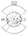
- FIG. 2 shows a plan view - without a roof - on the maintenance center 1 according to the invention.
- the maintenance center 1 is a sixteen-cornered building centrally grouped around an octagonal building center 4.
- a rotatable platform 5 is arranged in the building center 4.
- a lift is conceivable, with which the vehicle can be rotated in the raised state.
- each maintenance station 7 On each side 6 of the building center 4, substantially rectangular service places 7 abut, in whose gusset triangular surfaces 8 are provided.
- Each maintenance station 7 is equipped with corresponding installations, such as lift 9 different configurations, so for example scissor lift, 2- or 4-post lift or with a brake test 10.
- the individual triangular surfaces 8 have assembly workstations with corresponding structures, such as workbench 11 or tire mounting center 12.
- the supply lines required for the internals are permanently installed below the working surface of the maintenance stations 7. Therefore, the maintenance stations are doppelbödig trained.
- an additional space 12 is connected to the outside of a maintenance station 7 in FIG.
- the power supply facilities such as heating, compressed air, electrical, oil system with pumps and sanitary facilities for the employees of the maintenance center are housed.
- the ring lines 19 for the individual energy media.
- a further possible device in addition to the maintenance stations consists in the provision of an office / reception room 13 and a warehouse 14. These two rooms are separated from the other maintenance rooms by mobile walls and cover in this example, the base of a maintenance area with two connected triangular surfaces 8.
- the entrance for a motor vehicle takes place via a maintenance station 7, possibly with the interposition of a ramp 15.
- a maintenance station 7 possibly with the interposition of a ramp 15.
- the outer wall 3.3 with a roller door or sectional door or double doors provided.
- a workplace is used for this purpose with an installation, such as the brake test 10, which is not regularly occupied and on the entrance - due to the internals - is easily possible.
- the retracted motor vehicle is then driven onto the rotatable platform 5 in the building center 4 and can then be driven by turning the platform to a free maintenance place 7 or is driven to the maintenance station 7, where the upcoming maintenance can be performed.
- the exit of the motor vehicle can again take place via the same maintenance station as the entrance.
- a further maintenance station 7 with an outer wall 3.3, then takes place via the exit of the serviced motor vehicle.
- a view of a suitable sectional door 3.3 in front view is shown in an unfolded view.
- FIG. 3 shows a further embodiment of the invention.
- further building segments are connected to the building known from FIG. 2, whereby an octagonal building center is still present and the sixteen-cornered outside shape has been retained.
- exhibition areas 16 can be set up; but it is just as well conceivable to accommodate here storage areas 17 or a mix of both.
- exhibition areas 16 are provided, then correspondingly designed outer walls 18 (shown in unfolded view) are provided, which are equipped with corresponding glass surfaces in order to be able to view the objects to be exhibited, as a rule motor vehicles, from outside.
- the further building ring is not completely closed, but interrupted at least in the entrance and / or exit area.
- the described arrangement has the advantage that it requires little space, has no claims to the quality of the soil and also does not require architects. In addition, a quick regulatory approval is possible, so that such a maintenance center can be set up quickly. If a foil roof is provided, this will give the interior of the maintenance center and the eventual exhibition and storage rooms indirect light.
Landscapes
- Engineering & Computer Science (AREA)
- Architecture (AREA)
- Civil Engineering (AREA)
- Structural Engineering (AREA)
- Mechanical Engineering (AREA)
- Types And Forms Of Lifts (AREA)
- Power-Operated Mechanisms For Wings (AREA)
- Residential Or Office Buildings (AREA)
Description
- Die Erfindung bezieht sich auf ein Wartungscenter für Kraftfahrzeuge, insbesondere Personenkraftwagen, nach dem Oberbegriff des ersten Anspruchs. Ein solches Wartungscenter ist aus Dokument
DE-A-2 315 648 bekannt. - Aus der
DE 101 26 193 C1 ist ein innerstädtisches PKW-Verkaufs- und Wartungs-Center mit minimalem Grundflächenbedarf bekannt. Es besteht aus einem rechteckigen Turm mit einer Vielzahl von Geschossen, der zentral einen Aufzug für Fahrzeuge aufweist. Der Aufzug selbst weist eine drehbare Plattform für Fahrzeuge auf. Im Keller des Gebäudes ist ein Wartungscenter vorgesehen, bei dem die Wartungsplätze strahlenförmig von dem zentralen Aufzug aus gehen. Zwischen den einzelnen Wartungsplätzen sind unterschiedlich große Freiflächen vorhanden, die für Büros, Ersatzteillager, Sanitärräume, etc. genutzt werden können. - In dem Gebäude sind weiterhin Ausstellungsräume, Büros und andere Geschossflächen vorgesehen.
- Aufgabe der vorliegenden Erfindung ist es, ein Wartungscenter für Kraftfahrzeuge bereitzustellen, das schnell und preiswert aufzubauen ist und einen minimalen Flächenbedarf aufweist.
- Diese Aufgabe wird erfindungsgemäß durch die Merkmale des ersten Anspruchs gelöst. Der Grundgedanke des erfindungsgemäßen Wartungscenters besteht darin, dass es als fliegender Bau aus vorgefertigten, zerlegbaren Bauteilen besteht, wobei nur wenig geometrisch unterschiedliche Bauteile verwendet werden. Insbesondere kommen hier im Wesentlichen nur rechteckige, dreieckförmige Elemente für den Bodenbereich und Elemente für die Außenwände zur Anwendung. Damit kann eine hohe Flächennutzung von ca. 85 % der überbauten Fläche erzielt werden, während bei bisherigen Wartungscentern nur 60 - 70 % der überbauten Fläche genutzt wurde. Ein weiterer Vorteil der Erfindung ist darin zu sehen, dass kein Anspruch an die Bodenqualität gestellt wird, auf der das Wartungscenter errichtet wird, da Keller oder tragende Fundamente für hohe Lasten nicht benötigt werden.
- Die Unteransprüche beschreiben vorteilhafte Ausbildungen der Erfindung.
- Hierbei hat es sich als vorteilhaft erwiesen, die allgemeinen Versorgungsleitungen gemäß Anspruch 2 auszubilden.
- Die Weiterbildung nach Anspruch 3 hat den Vorteil, dass über einen Wartungsplatz das Fahrzeug in das Wartungscenter eingefahren werden kann und dann in Richtung auf einen freien Wartungsplatz bzw. auf den benötigten Wartungsplatz gefahren werden kann.
- Durch die Weiterbildung nach Anspruch 4 wird der Aufbau des Wartungscenters weiter erleichtert, da alle benötigten Einbauten bereits vormontiert an den Innenseiten der Außenwände angeordnet sind.
- Aufgrund des vorgeschlagenen Konzeptes des Wartungscenters benötigt man nur drei verschiedene Außenwände, wie Anspruch 5 vorschlägt.
- Allgemeine Einbauten, wie Heizung, Sanitär, zentrale Versorgung für Druckluft, Elektrik, etc. wird vorteilhafterweise gemäß Anspruch 6 in einem separaten Raum angeordnet, in dem dann auch die Ringleitungen beginnen und enden. Dieser separate Raum kann als Container ausgestattet sein, so dass die dort vorhandenen Aggregate bereits fest vormontiert sein können. Ein weiterer Vorteil dieser Anordnung besteht darin, dass sie einen Verzicht auf Anschlüsse zwischen dem Gebäude und dem Grundstück erlaubt (z.B. Blockheizkraftwerk, Warmwasser/Heizkreislaufsystem).
- Gemäß Anspruch 7 lässt sich das Wartungscenter sehr leicht mit einem Ausstellungsraum kombinieren, wenn in Verlängerung der Wartungsplätze die Ausstellungsräume angeordnet werden. Deren Grundfläche ist dann zwangsläufig größer, so dass genügend Platz zur Präsentation von Fahrzeugen oder anderen Ausstellungsgegenständen bleibt.
- Die Weiterbildung nach Anspruch 8 hat den Vorteil, dass bei Verwendung eines Foliendaches indirektes Licht auf die Wartungsplätze fällt, so dass eine lichttechnisch optimale Arbeitsumgebung herrscht.
- Im Folgenden wird die Erfindung anhand eines Beispiels näher erläutert.
- Figur 1
- zeigte eine Außenansicht eines Wartungscenters.
- Figur 2
- zeigt schematisiert eine Draufsicht auf das erfindungsgemäße Wartungscenter;
- Figur 3
- zeigt eine Erweiterung des Wartungscenters mit Ausstellungsflächen;
- In Figur 1 ist eine Vorderansicht eines erfindungsgemäßen Wartungscenters 1 beispielhaft dargestellt. Es ist ein sog. fliegender Bau, d.h. er ist aus einzelnen vorgefertigten Bauelementen aufgebaut. Er wird ohne Unterkellerung auf entsprechend dimensionierte und vorbereitete Fundamente gebaut.
- Das Wartungscenter 1 ist als eingeschossiger Bau konzipiert mit einem leicht gewölbten Dach 2, das als Foliendach aufgebaut sein kann. Die Außenwände 3 bestehen ebenfalls aus vorgefertigten Elementen gleicher Abmessungen. Es existieren lediglich wenige unterschiedlich ausgestaltete Außenwände 3, nämlich zum einen die vollständig geschlossene Form 3.1, dann eine verglaste Form 3.2 mit und ohne Eingängen für Personen und eine Außenwand 3.3, die als Tor ausgebildet ist, um mit einem Kraftfahrzeug hineinzufahren.
- Figur 2 zeigt eine Draufsicht - ohne Dach - auf das erfindungsgemäße Wartungscenter 1.
- Das Wartungscenter 1 ist ein sechzehneckiger Bau, der sich zentral um ein achteckiges Gebäudezentrum 4 gruppiert. In dem Gebäudezentrum 4 ist eine drehbare Plattform 5 angeordnet. Anstelle der Plattform 5 ist auch eine Hebebühne denkbar, mit welcher sich das Fahrzeug in angehobenem Zustand drehen lässt.
- An jeder Seite 6 des Gebäudezentrums 4 stoßen im Wesentlichen rechteckige Wartungsplätze 7 an, in deren Zwickel Dreiecksflächen 8 vorgesehen sind. Jeder Wartungsplatz 7 ist mit entsprechenden Einbauten, wie Hebebühne 9 unterschiedlicher Ausgestaltungen, also beispielsweise Scherenhebebühne, 2- oder 4-Säulenhebebühne oder mit einem Bremsenprüfstand 10 ausgestattet.
- Die einzelnen Dreiecksflächen 8 weisen Montagearbeitsplätze mit entsprechenden Aufbauten, wie Werkbank 11 oder Reifenmontagecenter 12, auf.
- Alle Einbauten oder Aufbauten sind bereits auf den Wartungsplätzen 7 vormontiert, so dass sie nur zu dem Wartungscenter zusammengefügt werden müssen.
- Die für die Einbauten benötigten Versorgungsleitungen sind unterhalb der Arbeitsfläche der Wartungsplätze 7 fest installiert. Deshalb sind die Wartungsplätze doppelbödig ausgebildet.
- Nach außen abgeschlossen sind die Wartungsplätze 7 - wie Figur 1 gezeigt hat - durch Außenwände 3, wobei in der Regel geschlossene Außenwände 3 an den Wartungsplätzen 7 vorgesehen sind.
- Auf der Innenseite der Außenwände 3 - soweit sie keine Türen oder Tore umfassen - sind weitere Wandeinbauten, wie Regale für Werkzeug, Werkstücke, wie Schrauben, Dichtungen, etc. oder für andere benötigte Hilfsmittel vorgesehen.
- Ebenfalls auf der Innenseite der Außenwände 3 im Bereich des Bodens der Wartungsplätze 7 verlaufen Versorgungsringleitungen 19, die die einzelnen Wartungsplätze 7 mit den benötigten Energien versorgt.
- Um die Energie bereitzustellen und hierbei nicht einen der acht Wartungsplätze zu opfern, ist in Figur 2 ein zusätzlicher Raum 12 außen an einem Wartungsplatz 7 angeschlossen. In diesem Raum, der ebenfalls als fliegender Bau entsprechend dem Wartungscenter 1 aufgebaut ist, sind die Energieversorgungseinrichtungen, wie Heizung, Druckluft, Elektro, Ölanlage mit Pumpen sowie Sanitär für die Mitarbeiter des Wartungscenters untergebracht. Hier enden dann naturgemäß auch die Ringleitungen 19 für die einzelnen Energiemedien.
- Eine weitere mögliche Einrichtung neben den Wartungsplätzen besteht im dem Vorsehen eines Büros/Empfangsraumes 13 sowie eines Lagers 14. Diese beiden Räume sind von den übrigen Wartungsräumen durch mobile Wände abgetrennt und überdecken in diesem Beispiel die Grundfläche eines Wartungsplatzes mit zwei angeschlossenen Dreiecksflächen 8. In dem Büroraum ist eine Außenwand 3.2 aus Glas mit einer zu öffnenden Tür vorgesehen, während in dem Lagerraum nur die geschlossenen Elemente 3.1 vorherrschen.
- Die Einfahrt für ein Kraftfahrzeug geschieht über einen Wartungsplatz 7, eventuell unter Zwischenschaltung einer Rampe 15 . Hierzu ist dann die Außenwand 3.3 mit einem Rolltor oder Sektionaltor oder Doppelflügeltüren vorgesehen. Zweckmäßigerweise wird hierzu ein Arbeitsplatz verwendet mit einem Einbau, beispielsweise dem Bremsenprüfstand 10, der nicht regelmäßig belegt ist und über die eine Einfahrt - aufgrund der Einbauten - problemlos möglich ist.
- Das eingefahrene Kraftfahrzeug wird dann auf die drehbare Plattform 5 im Gebäudezentrum 4 gefahren und kann dann durch Drehen der Plattform auf einen freien Wartungsplatz 7 gefahren werden bzw. wird auf den Wartungsplatz 7 gefahren, wo die anstehende Wartung durchgeführt werden kann.
- Die Ausfahrt des Kraftfahrzeuges kann wiederum über den gleichen Wartungsplatz wie die Einfahrt erfolgen. Es ist jedoch auch denkbar, einen weiteren Wartungsplatz 7 mit einer Außenwand 3.3 zu versehen, über den dann die Ausfahrt des gewarteten Kraftfahrzeuges erfolgt. Eine Ansicht eines geeigneten Sektionaltors 3.3 in Vorderansicht ist in einer ausgeklappten Ansicht dargestellt.
- In Figur 3 ist eine weitere Ausgestaltung der Erfindung dargestellt. Hier sind an dem aus Figur 2 bekannten Gebäude außen weiteren Gebäudesegmente angeschlossen, wobei nach wie vor ein achteckiges Gebäudezentrum vorhanden ist und die sechzehneckige Außenform beibehalten wurde. In diesen weiteren Räumen können Ausstellungsflächen 16 eingerichtet werden; es ist aber genauso gut denkbar, hier Lagerflächen 17 unterzubringen oder einen Mix aus beiden.
- Werden Ausstellungsflächen 16 vorgesehen, so sind hierfür entsprechend ausgebildete Außenwände 18 (in ausgeklappter Ansicht dargestellt) vorhanden, die mit entsprechenden Glasflächen ausgestattet sind, um die auszustellenden Gegenstände, in der Regel Kraftfahrzeuge, auch von außen betrachten zu können.
- Die nun zu Innenwänden gewandelten Außenwände des Wartungscenters sind wie in Figur 2 beschrieben ausgestaltet, um den Wartungsbereich vom Ausstellungsbereich zu trennen.
- Aufgrund der Ein- und/oder Ausfahrt aus dem Wartungscenter 1 ist der weitere Gebäudering nicht vollständig geschlossen, sondern zumindest in dem Einfahrt- und/oder Ausfahrtbereich unterbrochen.
- Die geschilderte Anordnung hat den Vorteil, dass sie wenig Fläche beansprucht, keine Ansprüche an die Bodenqualität aufweist und auch keinen Architekten verlangt. Zudem ist eine schnelle behördliche Genehmigung möglich, so dass ein derartiges Wartungscenter schnell aufgebaut werden kann. Falls ein Foliendach vorgesehen wird, erhält dadurch das Innere des Wartungszentrums und die eventuellen Ausstellungs- und Lagerräume indirektes Licht.
Claims (8)
- Wartungscenter für Kraftfahrzeuge, insbesondere Personenkraftwagen, mit einem vieleckigen Gebäudezentrum, dessen Außenkontur die doppelte Anzahl von Ecken aufweist wie im Gebäudezentrum, wobei im Gebäudezentrum eine drehbare Plattform vorgesehen ist und zwischen dieser Plattform und der Außenkontur des Gebäudes einzelne Wartungsplätze strahlenförmig angeordnet sind, die einen nahezu rechteckigen Grundriss aufweisen und wobei die zwischen den einzelnen Wartungsplätzen (7) verbleibenden Dreiecksflächen (8) zur Aufnahme von Montagewerkzeugen dienen,
dadurch gekennzeichnet, dass das Wartungscenter (1) als eingeschossiger Bau aus zerlegbaren, vorgefertigten Elementen besteht, dessen Boden doppelbödig ausgeführt ist, wobei in den Bodenhohlräumen Versorgungsleitungen angeordnet sind. - Wartungscenter nach einem der vorangegangenen Ansprüche,
dadurch gekennzeichnet, dass die Versorgungsleitungen zu den einzelnen Wartungsplätzen (7) als Ringleitungen (19) im Bereich der Außenwände (3) ausgebildet sind. - Wartungscenter nach einem der vorangegangenen Ansprüche,
dadurch gekennzeichnet, dass in dem Gebäudezentrum (4) eine Hebebühne mit drehbarem Tragemittel vorgesehen ist. - Wartungscenter nach einem der vorangegangenen Ansprüche,
dadurch gekennzeichnet, dass die Außenwände (3) auf ihrer Innenseite Wandeinbauten aufweisen. - Wartungscenter nach einem der vorangegangenen Ansprüche,
dadurch gekennzeichnet, dass die Außenwände (3) geschlossen (3.1) oder aus Glas (3.2) oder als Tor (3.3) ausgebildet sind. - Wartungscenter nach einem der vorangegangenen Ansprüche,
dadurch gekennzeichnet, dass sich an einer Außenwand (3) ein weiterer Raum anschließt. - Wartungscenter nach einem der vorangegangenen Ansprüche,
dadurch gekennzeichnet, dass außen um die Wartungsplätze (7) weitere Räume, die als Ausstellungsflächen (16) ausgestaltet sind, segmentförmig angeordnet sind. - Wartungscenter nach einem der vorangegangenen Ansprüche,
dadurch gekennzeichnet, dass das Dach (2) des Wartungscenters (1) als Foliendach aufgebaut ist.
Applications Claiming Priority (2)
| Application Number | Priority Date | Filing Date | Title |
|---|---|---|---|
| DE10358524 | 2003-12-13 | ||
| DE2003158524 DE10358524A1 (de) | 2003-12-13 | 2003-12-13 | Wartungscenter für Kraftfahrzeuge |
Publications (2)
| Publication Number | Publication Date |
|---|---|
| EP1541785A1 EP1541785A1 (de) | 2005-06-15 |
| EP1541785B1 true EP1541785B1 (de) | 2008-01-09 |
Family
ID=34485374
Family Applications (1)
| Application Number | Title | Priority Date | Filing Date |
|---|---|---|---|
| EP20040026111 Expired - Lifetime EP1541785B1 (de) | 2003-12-13 | 2004-11-04 | Wartungscenter für Kraftfahrzeuge |
Country Status (2)
| Country | Link |
|---|---|
| EP (1) | EP1541785B1 (de) |
| DE (2) | DE10358524A1 (de) |
Cited By (1)
| Publication number | Priority date | Publication date | Assignee | Title |
|---|---|---|---|---|
| RU2775888C1 (ru) * | 2020-10-05 | 2022-07-11 | Федеральное государственное казенное военное образовательное учреждение высшего образования "ВОЕННАЯ АКАДЕМИЯ МАТЕРИАЛЬНО-ТЕХНИЧЕСКОГО ОБЕСПЕЧЕНИЯ имени генерала армии А.В. Хрулева" Министерства обороны Российской Федерации | Мобильная станция технического сервиса вооружения, военной и специальной техники в условиях Арктической зоны Российской Федерации |
Families Citing this family (6)
| Publication number | Priority date | Publication date | Assignee | Title |
|---|---|---|---|---|
| CN103031966B (zh) * | 2011-09-30 | 2015-05-27 | 国家电网公司 | 一种水轮机和发电机大轴检修平台 |
| CN103291103B (zh) * | 2013-05-23 | 2016-03-16 | 胡新宜 | 一种多层圆形移动停车盘自动存取车库和货仓的组合装置 |
| CN106401240B (zh) * | 2016-09-12 | 2018-07-20 | 中国电子科技集团公司第三十八研究所 | 立体停车库的车位数量排布的设计方法 |
| US20190023236A1 (en) * | 2017-07-19 | 2019-01-24 | Ronald Michael Webb | Autonomous vehicle service station, systems and methods |
| RU186308U1 (ru) * | 2018-11-06 | 2019-01-15 | Сергей Иванович Малухин | Поворотное устройство для парковки транспортного средства |
| CN109972866B (zh) * | 2019-04-18 | 2024-03-15 | 台州职业技术学院 | 一种悬挑式公共厕所 |
Family Cites Families (10)
| Publication number | Priority date | Publication date | Assignee | Title |
|---|---|---|---|---|
| US1813460A (en) * | 1928-05-11 | 1931-07-07 | Herman A Mugler | Multiple automobile pit |
| US3079871A (en) * | 1960-06-06 | 1963-03-05 | Brodie Nathan | Automotive service building |
| DE2315648C2 (de) * | 1973-03-29 | 1984-07-19 | Uwe 4600 Dortmund Kochanneck | Hochgarage |
| DE2322808A1 (de) * | 1973-05-05 | 1974-11-21 | Uwe Kochanneck | Automatische hochgarage mit kombinierten autoreparatureinrichtungen |
| DE9314160U1 (de) * | 1993-09-20 | 1994-01-13 | Bauer, Heiner, Dipl.-Ing. (FH), 90602 Pyrbaum | Serienmäßig vorfertigbare Teilbaukörper und deren Anordnung für die Erstellung von Gebäuden |
| WO1996023117A1 (fr) * | 1995-01-26 | 1996-08-01 | Veedol France S.A. | Procede de construction de structures pour services automobiles et structure |
| US5980185A (en) * | 1997-07-30 | 1999-11-09 | Vita Auto Stack, Inc. | Vehicle parking structure |
| IT1303843B1 (it) * | 1998-11-20 | 2001-03-01 | Stefano E Pietrafraccia | Stazioni prefabbricate modulari per lavaggio e servizi vari adautoveicoli e loro metodo di montaggio |
| EP1245759A1 (de) * | 2001-03-27 | 2002-10-02 | RIRI Privatstiftung | Transportable Werkstätte |
| DE10126193C1 (de) * | 2001-05-30 | 2002-10-10 | Daimler Chrysler Ag | Innerstädtisches PKW-Verkaufs-und Wartungs-Center mit minimalem Grundflächenbedarf |
-
2003
- 2003-12-13 DE DE2003158524 patent/DE10358524A1/de not_active Withdrawn
-
2004
- 2004-11-04 EP EP20040026111 patent/EP1541785B1/de not_active Expired - Lifetime
- 2004-11-04 DE DE200450005895 patent/DE502004005895D1/de not_active Expired - Lifetime
Cited By (1)
| Publication number | Priority date | Publication date | Assignee | Title |
|---|---|---|---|---|
| RU2775888C1 (ru) * | 2020-10-05 | 2022-07-11 | Федеральное государственное казенное военное образовательное учреждение высшего образования "ВОЕННАЯ АКАДЕМИЯ МАТЕРИАЛЬНО-ТЕХНИЧЕСКОГО ОБЕСПЕЧЕНИЯ имени генерала армии А.В. Хрулева" Министерства обороны Российской Федерации | Мобильная станция технического сервиса вооружения, военной и специальной техники в условиях Арктической зоны Российской Федерации |
Also Published As
| Publication number | Publication date |
|---|---|
| DE10358524A1 (de) | 2005-07-07 |
| DE502004005895D1 (de) | 2008-02-21 |
| EP1541785A1 (de) | 2005-06-15 |
Similar Documents
| Publication | Publication Date | Title |
|---|---|---|
| EP0881975B1 (de) | Schienenfahrzeug mit wagenkasten | |
| EP1646557A1 (de) | Flugzeug | |
| DE102013207392A1 (de) | Raumsystem | |
| WO2002097220A1 (de) | Innerstädtisches pkw-verkaufs- und wartungs-center mit minimalen grundflächenbedarf | |
| EP1765641B1 (de) | Mobile sanitäranlage zur ortsunabhängigen sanitären versorgung einer vielzahl von personen | |
| EP2228130B1 (de) | Modularer Reinraum | |
| EP1541785A1 (de) | Wartungscenter für Kraftfahrzeuge | |
| DE2364021A1 (de) | Mobile raumeinheit | |
| WO2004101342A1 (de) | Dachseitige innenverkleidung eines grossräumigen fahrzeuges zur personenbeförderung, insbesondere eines schienenfahrzeuges | |
| DE10339508A1 (de) | Flugzeug | |
| AT525626B1 (de) | Mobile Containerraumvorrichtung | |
| DE19907232B4 (de) | Mobile Trennwand mit Abschlußprofil | |
| DE3035711A1 (de) | Transportable krankenstation | |
| DE20209988U1 (de) | Parksystem für Personenkraftwagen | |
| DE1921720U (de) | Vorgetertigte plattform fuer fahrzeug-garagen. | |
| EP1264947B1 (de) | Gebäude, insbesondere Hotel- oder Appartementgebäude | |
| DE102007037943B4 (de) | Beleuchtungsanordnung | |
| EP0621228B1 (de) | Krantürme und Verfahren zu ihrer Montage | |
| DE29608412U1 (de) | Flurcontainer | |
| DE9113701U1 (de) | Transportabler Container mit veränderbarer Grundfläche | |
| DE102005035175A1 (de) | Klappbarer Versorgungscontainer | |
| DE20119317U1 (de) | Mehrgeschossiges Gebäude | |
| DE2422867A1 (de) | Abdeck-kuppel | |
| DE10149046A1 (de) | Modulares Leistungszentrum zum Bereitstellen von sozialen und medizinischen Dienstleistungen | |
| EP1163411B1 (de) | Anordnung zur sicherung eines fahrzeug-abstellplatzes |
Legal Events
| Date | Code | Title | Description |
|---|---|---|---|
| PUAI | Public reference made under article 153(3) epc to a published international application that has entered the european phase |
Free format text: ORIGINAL CODE: 0009012 |
|
| AK | Designated contracting states |
Kind code of ref document: A1 Designated state(s): AT BE BG CH CY CZ DE DK EE ES FI FR GB GR HU IE IS IT LI LU MC NL PL PT RO SE SI SK TR |
|
| AX | Request for extension of the european patent |
Extension state: AL HR LT LV MK YU |
|
| 17P | Request for examination filed |
Effective date: 20050713 |
|
| AKX | Designation fees paid |
Designated state(s): DE FR GB IT |
|
| 17Q | First examination report despatched |
Effective date: 20061124 |
|
| GRAP | Despatch of communication of intention to grant a patent |
Free format text: ORIGINAL CODE: EPIDOSNIGR1 |
|
| GRAS | Grant fee paid |
Free format text: ORIGINAL CODE: EPIDOSNIGR3 |
|
| GRAA | (expected) grant |
Free format text: ORIGINAL CODE: 0009210 |
|
| AK | Designated contracting states |
Kind code of ref document: B1 Designated state(s): DE FR GB IT |
|
| REG | Reference to a national code |
Ref country code: GB Ref legal event code: FG4D Free format text: NOT ENGLISH |
|
| GBT | Gb: translation of ep patent filed (gb section 77(6)(a)/1977) |
Effective date: 20080124 |
|
| REF | Corresponds to: |
Ref document number: 502004005895 Country of ref document: DE Date of ref document: 20080221 Kind code of ref document: P |
|
| ET | Fr: translation filed | ||
| PLBE | No opposition filed within time limit |
Free format text: ORIGINAL CODE: 0009261 |
|
| STAA | Information on the status of an ep patent application or granted ep patent |
Free format text: STATUS: NO OPPOSITION FILED WITHIN TIME LIMIT |
|
| 26N | No opposition filed |
Effective date: 20081010 |
|
| PGFP | Annual fee paid to national office [announced via postgrant information from national office to epo] |
Ref country code: FR Payment date: 20101210 Year of fee payment: 7 |
|
| PGFP | Annual fee paid to national office [announced via postgrant information from national office to epo] |
Ref country code: GB Payment date: 20101126 Year of fee payment: 7 Ref country code: IT Payment date: 20101126 Year of fee payment: 7 |
|
| PGFP | Annual fee paid to national office [announced via postgrant information from national office to epo] |
Ref country code: DE Payment date: 20110113 Year of fee payment: 7 |
|
| GBPC | Gb: european patent ceased through non-payment of renewal fee |
Effective date: 20111104 |
|
| REG | Reference to a national code |
Ref country code: FR Ref legal event code: ST Effective date: 20120731 |
|
| PG25 | Lapsed in a contracting state [announced via postgrant information from national office to epo] |
Ref country code: IT Free format text: LAPSE BECAUSE OF NON-PAYMENT OF DUE FEES Effective date: 20111104 |
|
| REG | Reference to a national code |
Ref country code: DE Ref legal event code: R119 Ref document number: 502004005895 Country of ref document: DE Effective date: 20120601 |
|
| PG25 | Lapsed in a contracting state [announced via postgrant information from national office to epo] |
Ref country code: GB Free format text: LAPSE BECAUSE OF NON-PAYMENT OF DUE FEES Effective date: 20111104 |
|
| PG25 | Lapsed in a contracting state [announced via postgrant information from national office to epo] |
Ref country code: FR Free format text: LAPSE BECAUSE OF NON-PAYMENT OF DUE FEES Effective date: 20111130 |
|
| PG25 | Lapsed in a contracting state [announced via postgrant information from national office to epo] |
Ref country code: DE Free format text: LAPSE BECAUSE OF NON-PAYMENT OF DUE FEES Effective date: 20120601 |