EP1541507B1 - Pneumatic conveying - Google Patents
Pneumatic conveying Download PDFInfo
- Publication number
- EP1541507B1 EP1541507B1 EP05005350A EP05005350A EP1541507B1 EP 1541507 B1 EP1541507 B1 EP 1541507B1 EP 05005350 A EP05005350 A EP 05005350A EP 05005350 A EP05005350 A EP 05005350A EP 1541507 B1 EP1541507 B1 EP 1541507B1
- Authority
- EP
- European Patent Office
- Prior art keywords
- vessel
- pipe
- vessels
- container
- cuttings
- Prior art date
- Legal status (The legal status is an assumption and is not a legal conclusion. Google has not performed a legal analysis and makes no representation as to the accuracy of the status listed.)
- Expired - Lifetime
Links
Images


Classifications
-
- B—PERFORMING OPERATIONS; TRANSPORTING
- B63—SHIPS OR OTHER WATERBORNE VESSELS; RELATED EQUIPMENT
- B63B—SHIPS OR OTHER WATERBORNE VESSELS; EQUIPMENT FOR SHIPPING
- B63B27/00—Arrangement of ship-based loading or unloading equipment for cargo or passengers
- B63B27/30—Arrangement of ship-based loading or unloading equipment for transfer at sea between ships or between ships and off-shore structures
- B63B27/34—Arrangement of ship-based loading or unloading equipment for transfer at sea between ships or between ships and off-shore structures using pipe-lines
-
- B—PERFORMING OPERATIONS; TRANSPORTING
- B63—SHIPS OR OTHER WATERBORNE VESSELS; RELATED EQUIPMENT
- B63B—SHIPS OR OTHER WATERBORNE VESSELS; EQUIPMENT FOR SHIPPING
- B63B27/00—Arrangement of ship-based loading or unloading equipment for cargo or passengers
- B63B27/24—Arrangement of ship-based loading or unloading equipment for cargo or passengers of pipe-lines
-
- B—PERFORMING OPERATIONS; TRANSPORTING
- B65—CONVEYING; PACKING; STORING; HANDLING THIN OR FILAMENTARY MATERIAL
- B65G—TRANSPORT OR STORAGE DEVICES, e.g. CONVEYORS FOR LOADING OR TIPPING, SHOP CONVEYOR SYSTEMS OR PNEUMATIC TUBE CONVEYORS
- B65G53/00—Conveying materials in bulk through troughs, pipes or tubes by floating the materials or by flow of gas, liquid or foam
- B65G53/04—Conveying materials in bulk pneumatically through pipes or tubes; Air slides
- B65G53/06—Gas pressure systems operating without fluidisation of the materials
- B65G53/10—Gas pressure systems operating without fluidisation of the materials with pneumatic injection of the materials by the propelling gas
- B65G53/12—Gas pressure systems operating without fluidisation of the materials with pneumatic injection of the materials by the propelling gas the gas flow acting directly on the materials in a reservoir
-
- B—PERFORMING OPERATIONS; TRANSPORTING
- B65—CONVEYING; PACKING; STORING; HANDLING THIN OR FILAMENTARY MATERIAL
- B65G—TRANSPORT OR STORAGE DEVICES, e.g. CONVEYORS FOR LOADING OR TIPPING, SHOP CONVEYOR SYSTEMS OR PNEUMATIC TUBE CONVEYORS
- B65G53/00—Conveying materials in bulk through troughs, pipes or tubes by floating the materials or by flow of gas, liquid or foam
- B65G53/34—Details
- B65G53/36—Arrangements of containers
Definitions
- This invention relates to pneumatic conveying and, in particular, to the conveying of materials which are in the form of thick, heavy pastes which are normally difficult to move and handle.
- the oil contaminated cuttings are screened to remove a high proportion of the oil for re-use on the rig.
- the cuttings which are still contaminated with some oil, are transported ashore in the form of a very thick heavy paste.
- the material is put into special skips of about 10 ton capacity which are loaded by crane from the rig onto supply boats. This is a difficult and dangerous operation in bad weather and is laborious and expensive.
- the present invention is based on surprising discovery that it is possible to transport a material in the form of a thick heavy paste by means of pneumatic conveying from a relatively large vessel Hitherto, it has been supposed that pneumatic conveying systems were only suitable for relatively free flowing material or conveying of small batches of wet sticky materials.
- a method of conveying a non-free flowing paste comprising loading the paste into a transportable vessel and applying a compressed gas to the vessel to cause the material to flow out of the vessel.
- the non-free flowing paste may be a thick and/or heavy paste or clay like material, e.g. oil rig drill cuttings.
- the transportable vessel is preferably a combined storage and pneumatic conveying vessel.
- the compressed gas is preferably compressed air, because it is relatively inexpensive although in certain instances an inert gas may be used, for example, compressed nitrogen.
- the vessel is provided with an inlet and an outlet, such that loading of the vessel is via the inlet.
- the outlet is connected to a conduit which leads to the final desired destination of the material.
- the method of the invention also includes the step of transporting the vessel, having at least partially filled it with said material, from its filling station to a discharge station. At the discharge station, compressed air is applied to the interior of the vessel to convey the material out of the vessel to its destination.
- the vessel includes a conical hopper portion which, at least during discharge of the material, forms the lower section of the vessel.
- the lower conical hopper portion is the outlet end of the vessel.
- the pressure used in the vessel in the method may also vary depending upon the nature of the material. However, we have found that a pressure of between 4 and 8 bar is suitable.
- the drill cuttings are loaded into a first relatively small vessel capable of being pressurised from which said material is fed under pressure via a pipe to one or more further vessels also capable of being pressurised.
- Said further vessels may be transported to a position where discharge of material takes place or said further vessels may remain in their original position and the material is discharged from them into yet further vessels which are themselves transported to the destination.
- the present invention also provides apparatus for conveying a material in the form of a thick, heavy paste, the apparatus comprising a vessel capable of being pressurised by compressed gas, said vessel having a material inlet, a material outlet and a pipe connected to said material outlet, means for loading the material into said vessel through said inlet, gas supply means for supplying compressed gas to said vessel to cause the material to flow out of the vessel via said outlet and along said pipe.
- the apparatus of the invention comp[rises a vessel adapted to be pressurised by compressed gas to between 4 and 8 bar.
- an off shore oil rig 1 has located on its platform 3 a pressure vessel 5 into which is loaded the screened drill cuttings arising from the drilling process.
- This pressure vessel 5 includes an upper material inlet and a lower material outlet as well as means for supplying compressed air to the interior of the vessel.
- the material inlet includes a valve assembly similar to that described in GB-A-1539079 and the entire vessel may be similar to that manufactured and sold by Clyde Materials Handling Limited (Clyde).
- the pneumatic conveying system including the pressure vessel 5 follows a cycle of filling and discharging material from the pressure vessel.
- the material inlet valve in the Clyde system this valve includes a part spherical closure member
- a vent valve is opened to equalise vessel pressure to ambient air.
- the inlet valve is opened and the oil cuttings/oil mixture is fed into the pressurised vessel.
- the vent valve is opened to vent displaced air from the vessel.
- the inlet valve closes.
- the vent valve also closes and the vessel is now sealed.
- An air inlet valve is opened and the material is conveyed in the form of a semi solid slug along pipe 7.
- pipe 7 extends from a position below pressurised vessel 5 to an elevated position above a container assembly 9.
- Assembly 9 comprises three ISO container sized vessels 11 located within a support framework 13. (In other embodiments, the container assembly may include a number of vessels 11 other than three).
- Pipe 7 extends above the top of container assembly 9 and has downwardly extending branches leading into the inlets of each of the containers 11.
- Each container 1 I has a lower conical shaped hopper portion 15 and at the lowermost point of this portion there is a valve inlet 17 whereby the material within the containers 11 may be discharged via pipe 19 to a hose connection pipe 21.
- a supply boat 23, fitted with a further container assembly 25, may be brought close to the oil rig 1.
- a flexible hose 27 is connected to pipe 19 at hose connection pipe 21.
- hose 27 is connected to a filling pipe 29 located on boat 23.
- Filling pipe 29 leads from the rear of boat 23 to a position above container assembly 25 and branch pipes extends downwardly from pipe 29 to the inlets of each of the containers 31 forming part of the containers assembly 25.
- vessels 33 for feeding the drill cuttings/oil mixture to the container assembly 9.
- FIG. 3 and 4 of the accompanying drawings there is illustrated an arrangement broadly similar to that described above with reference to Figures 1 and 2.
- the drill cuttings/oil mixture is fed from the container assembly 9 located on oil rig platform 3.
- a container assembly 41 is located on boat 23, the containers in this container assembly being arranged with their longitudinal axes extending horizontally rather than vertically as in the case of the Figure 1 embodiment.
- the feed pipe 29 again extends to a position above the container assembly 41 and has branch pipes 43 extending downwardly into inlets in each container which are located in the side of the container.
- FIG. 5 of the accompanying drawings there is illustrated a first stage in the method of the present invention described above with reference to Figures I and 2.
- a discharge pipe 51 extends from outlet 17 of each of the containers 25.
- This pipe 27 may be connected to a flexible hose 53 which extends from connection point 55 located on ship 23 to a further connection point 57 located on land.
- Extending from connection point 57 is pipe 59 which leads to an elevated position above a large container 61.
- Pipe 59 is connected to an inlet 63 at the top of container 61.
- Container 61 is broadly similar in shape to containers 25 having a lower conical shape portion 65. When desired the material loaded into container 61 may be discharged via a lower outlet 67.
- the process of feeding the drill cuttings/oil mixture from containers 25 to large container 61 involves pneumatic conveying similar to that described above in connection with the conveying of the material from pressure vessel 5 to containers 11.
- FIG. 7 of the accompanying drawings there is illustrated an ISO container sized conveying vessel 31 located within a support frame 81 and being positioned with its longitudinal axis arranged horizontally ( Figures 7a and 7b) and with this axis lying vertically ( Figure 7c).
- Vessel 31 has a part spherical shaped upper end 83, a cylindrical main body section 85 and a lower conical section 87. At the lowermost end of conical section 87, the vessel is provided with a discharge valve 89.
- a container assembly 91 comprising containers 93, each located with a support frame 95.
- a filling pipe 97 extends into each container via a valve 99 and, where appropriate a branch pipe 101, the container inlet being located in the upper end 83 of the container.
- a compressed air line 103 Also extending into the upper end of each container 93 is a compressed air line 103 having valves 105. Any number of containers may be connected in this way with a common material filling pipe and a common material discharge pipe.
- each container 93 At the lower end of each container 93 is a discharge valve 89 having connected thereto a pipe 107 via, if appropriate, a branch pipe 109.
- valve 99 In order to empty a vessel filled via pipe 97, valve 99 is closed, valve 89 is opened and compressed air is fed to the vessel via air line 103.
- the drill cuttings/oil mixture is forced out of vessel 93 under the pressure of the compressed air and into pipe 107. Due to the conical angle of the conical or hopper section 93 being less than a certain value, the material flow out of container 93 is of the type known as mass flow and results in all of the material exiting uniformly out of the container.
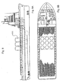
- FIG. 9 there is illustrated in both elevation ( Figure 9a) and in plan ( Figure 9b) a supply boat which is fitted with large conveying vessels 111 which extend through the deck of the boat.
- This arrangement can hold up to thousand tons of drill cuttings/oil mixture and this mixture can be pumped pneumatically from the tanks onto shore based storage containers.
- the conveying vessels 111 have a cone angle such that mass flow occurs and they work in a similar way to the assembly of Figure 8.
- FIG. 10 of the accompanying drawings there is illustrated another embodiment of a supply boat illustrated in elevation ( Figure 10a) and in plan ( Figure 10b).
- the boat is for conveying containers 113 which fit within the envelope of a 20ft ISO container frame.
- ISO container vessels enables supply boats to be used in substantially unmodified form.
- Methods- of the present invention involving the use of ISO container vessels may be operated in a different way.
- a number of empty ISO container vessels is lifted onto the drilling rig by the rig crane.
- the vessels are stood on end on support frames incorporating the discharge piping and they are assembled into a line of storage vessels each of which can store about twenty tons of cuttings/oil.
- a pressurised vessel 5 (see Figure 1) is used to transfer the cuttings/oil from screens or centrifuges into the ISO conveying vessels. These vessels are then used to transfer the stored contents onto the supply boat as described above in connection with Figure 1.
- An advantage of this method is that there is a buffer storage on the rig so that drilling can occur when the supply boat is not present. Furthermore transfer rates from the rig are much higher than is possible if a standard pneumatic conveyor system (such as the Clyde system) is used alone. In addition hose sizes can be minimised.
- An alternative embodiment making use of the ISO container vessels involves the use of these vessels on the supplied boat. Thirty or forty of these vessels may be stood on end and rafted together to form a stable structure into which 400 or 500 tons of cuttings can be conveyed, as illustrated in Figure 10.
- the contents of the container vessels may be pneumatically transferred ashore.
- the tanks may be lifted off by cranes, turned horizontal and loaded onto standard ISO container road vehicles. If appropriate they could also be stacked on the quay side in the same way that containers are currently stacked.
- the containers are received at the processing plant they are stood on end and used as conveying vessels to transfer the cuttings/oil into their destination.
- the drill cuttings/oil mixture is stored in large volumes in the legs of semi-submersible oil rigs or drilling platforms.
- the legs are typically 15m diameter. Pressurised vessels located in the legs and operating on the same principles as described above will store the cuttings/oil mixture and then be used as pneumatic conveying vessels to transfer the material onto the supply boat.
- Such linings may be used in conjunction with the use of the mass flow cone angle, as described above, to aid discharge of the drill cuttings from the internal surfaces of the pressure vessels.
Abstract
Description
- This invention relates to pneumatic conveying and, in particular, to the conveying of materials which are in the form of thick, heavy pastes which are normally difficult to move and handle.
- An example of the sort of material with which this invention is concerned is provided by the oil exploration industry. When oil wells are drilled, the cuttings from the drilling operations are brought up onto the drilling platform. For a large part of the drilling operation, a special type of oil is pumped down to the drilling bits as a lubricant. The oil contaminated material which comes up onto the drilling platform has until recently been dumped into the sea. For environmental reasons, such disposal is no longer permitted and the material now has to be transported to the shore for processing.
- On the drilling rig, the oil contaminated cuttings are screened to remove a high proportion of the oil for re-use on the rig. The cuttings, which are still contaminated with some oil, are transported ashore in the form of a very thick heavy paste. Typically the material is put into special skips of about 10 ton capacity which are loaded by crane from the rig onto supply boats. This is a difficult and dangerous operation in bad weather and is laborious and expensive.
- We have now surprisingly found a novel method of transferring thick heavy pastes material e.g. drill cuttings which has not been previously possible.
- Accordingly, the present invention is based on surprising discovery that it is possible to transport a material in the form of a thick heavy paste by means of pneumatic conveying from a relatively large vessel Hitherto, it has been supposed that pneumatic conveying systems were only suitable for relatively free flowing material or conveying of small batches of wet sticky materials.
- Thus, according to the present invention there is provided a method of conveying a non-free flowing paste comprising loading the paste into a transportable vessel and applying a compressed gas to the vessel to cause the material to flow out of the vessel.
- The non-free flowing paste may be a thick and/or heavy paste or clay like material, e.g. oil rig drill cuttings.
- Thus the transportable vessel is preferably a combined storage and pneumatic conveying vessel.
- The compressed gas is preferably compressed air, because it is relatively inexpensive although in certain instances an inert gas may be used, for example, compressed nitrogen.
- The vessel is provided with an inlet and an outlet, such that loading of the vessel is via the inlet. Preferentially the outlet is connected to a conduit which leads to the final desired destination of the material.
- In a preferred embodiment the method of the invention also includes the step of transporting the vessel, having at least partially filled it with said material, from its filling station to a discharge station. At the discharge station, compressed air is applied to the interior of the vessel to convey the material out of the vessel to its destination.
- Preferably the vessel includes a conical hopper portion which, at least during discharge of the material, forms the lower section of the vessel. In a further preferred embodiment, the lower conical hopper portion is the outlet end of the vessel.
- Because of the nature of the material being handled in the method of the present invention, there is a tendency for the flow of the material out of the vessel to be less than complete. This is because the type of flow which occurs during discharge is of a form known as core flow or funnel flow. When this type of flow occurs, the material directly above the outlet falls through the outlet, e.g. the outlet valve, so that a falling core of material is created directly above the outlet. However, with sticky materials, the material around this core does not move. As the core falls, a depression occurs in the top surface of the material and the material surrounding that depression falls into the core. In the case of a sticky material there is a tendency for material around the core to remain in the vessel.
- It has been discovered that even for the sort of material with which this invention is concerned, it is possible to change the nature of the flow out of the vessel by altering the cone angle of the lower conical portion of the vessel. If the included cone angle is changed below a certain or critical value, then the flow changes from core flow to so-called mass flow. In the case of mass flow, the material descends as a mass in a uniform way towards the outlet with all the material moving. Accordingly the combination of the use of a vessel designed to achieve mass flow and the application of a compressed gas above the surface of the material is such that it is possible to push the contents of the vessel through the outlet so as fully to empty the vessel.
- It is well known that the critical cone angle will vary depending upon the material being conveyed as such would be well understood by those skilled in the art.
- The pressure used in the vessel in the method may also vary depending upon the nature of the material. However, we have found that a pressure of between 4 and 8 bar is suitable.
- In an embodiment of the present invention the drill cuttings are loaded into a first relatively small vessel capable of being pressurised from which said material is fed under pressure via a pipe to one or more further vessels also capable of being pressurised. Said further vessels may be transported to a position where discharge of material takes place or said further vessels may remain in their original position and the material is discharged from them into yet further vessels which are themselves transported to the destination.
- The present invention also provides apparatus for conveying a material in the form of a thick, heavy paste, the apparatus comprising a vessel capable of being pressurised by compressed gas, said vessel having a material inlet, a material outlet and a pipe connected to said material outlet, means for loading the material into said vessel through said inlet, gas supply means for supplying compressed gas to said vessel to cause the material to flow out of the vessel via said outlet and along said pipe.
- Conventionally known pressure vessels are expected to withstand a maximum pressure of 2 bar. Thus, in a preferred embodiment the apparatus of the invention comp[rises a vessel adapted to be pressurised by compressed gas to between 4 and 8 bar.
-
- Figure 1 is an elevation showing the operation of a first method in accordance with the present invention;
- Figure 2 is a plan view of Figure 1;
- Figure 3 is an elevation showing the operation of a second method in accordance with the present invention;
- Figure 4 is a planned view of Figure 3;
- Figure 5 is an elevation showing a continuation of the operation of the method illustrated in Figure 1;
- Figure 6 is an elevation showing the continuation of the operation of the method of Figure 3;
- Figure 7 shows details of a standard ISO container sized vessel which may be used in the method of the present invention;
- Figure 8 shows an assembly of two ISO container sized vessels;
- Figure 9 shows an oil rig supply boat including vessels which may be used in a method of the present invention;
- Figure 10 is an alternative embodiment of an oil rig supply vessel including vessels of use in a method of the present invention.
- Embodiments of the present invention will now be described, by way of examples only, and with reference to the accompanying drawings.
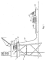
- Referring to Figure 1 of the accompanying drawings, an off shore oil rig 1 has located on its platform 3 a pressure vessel 5 into which is loaded the screened drill cuttings arising from the drilling process. This pressure vessel 5 includes an upper material inlet and a lower material outlet as well as means for supplying compressed air to the interior of the vessel. The material inlet includes a valve assembly similar to that described in GB-A-1539079 and the entire vessel may be similar to that manufactured and sold by Clyde Materials Handling Limited (Clyde).
- In operation the pneumatic conveying system, including the pressure vessel 5, follows a cycle of filling and discharging material from the pressure vessel. At the start of the cycle, the material inlet valve (in the Clyde system this valve includes a part spherical closure member) is closed. A vent valve is opened to equalise vessel pressure to ambient air. The inlet valve is opened and the oil cuttings/oil mixture is fed into the pressurised vessel. The vent valve is opened to vent displaced air from the vessel. When the pressurised vessel is full, the inlet valve closes. The vent valve also closes and the vessel is now sealed. An air inlet valve is opened and the material is conveyed in the form of a semi solid slug along pipe 7.
- As indicated in Figure 1, pipe 7 extends from a position below pressurised vessel 5 to an elevated position above a
container assembly 9.Assembly 9 comprises three ISO container sized vessels 11 located within asupport framework 13. (In other embodiments, the container assembly may include a number of vessels 11 other than three). Pipe 7 extends above the top ofcontainer assembly 9 and has downwardly extending branches leading into the inlets of each of the containers 11. - Each container 1 I has a lower conical shaped
hopper portion 15 and at the lowermost point of this portion there is avalve inlet 17 whereby the material within the containers 11 may be discharged viapipe 19 to a hose connection pipe 21. - A
supply boat 23, fitted with afurther container assembly 25, may be brought close to the oil rig 1. Aflexible hose 27 is connected topipe 19 at hose connection pipe 21. At itsother end hose 27 is connected to a fillingpipe 29 located onboat 23. Fillingpipe 29 leads from the rear ofboat 23 to a position abovecontainer assembly 25 and branch pipes extends downwardly frompipe 29 to the inlets of each of thecontainers 31 forming part of thecontainers assembly 25. - As illustrated in Figure 2, there may be further pressure vessels such as
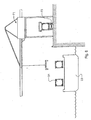
vessels 33 for feeding the drill cuttings/oil mixture to thecontainer assembly 9. - Referring to Figure 3 and 4 of the accompanying drawings, there is illustrated an arrangement broadly similar to that described above with reference to Figures 1 and 2. However, in this case the drill cuttings/oil mixture is fed from the
container assembly 9 located onoil rig platform 3. Acontainer assembly 41 is located onboat 23, the containers in this container assembly being arranged with their longitudinal axes extending horizontally rather than vertically as in the case of the Figure 1 embodiment. Thefeed pipe 29 again extends to a position above thecontainer assembly 41 and has branch pipes 43 extending downwardly into inlets in each container which are located in the side of the container. - As better shown in Figure 4, there are in fact two
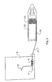
container assemblies 41, each of which is provided with afeed pipe 29 which may be connected toflexible hose 27. - Referring to Figure 5 of the accompanying drawings, there is illustrated a first stage in the method of the present invention described above with reference to Figures I and 2. Following the loading of the
containers 25 onboat 23, the boat is moved to shore where the unloading process is carried out. Adischarge pipe 51 extends fromoutlet 17 of each of thecontainers 25. Thispipe 27 may be connected to aflexible hose 53 which extends fromconnection point 55 located onship 23 to afurther connection point 57 located on land. Extending fromconnection point 57 ispipe 59 which leads to an elevated position above alarge container 61.Pipe 59 is connected to aninlet 63 at the top ofcontainer 61.Container 61 is broadly similar in shape tocontainers 25 having a lowerconical shape portion 65. When desired the material loaded intocontainer 61 may be discharged via alower outlet 67. - The process of feeding the drill cuttings/oil mixture from
containers 25 tolarge container 61 involves pneumatic conveying similar to that described above in connection with the conveying of the material from pressure vessel 5 to containers 11. - Referring to Figure 6 of the accompanying drawings, there is illustrated a further stage in the method described above with reference to Figures 3 and 4.
Supply boat 23, having had itscontainers 31 loaded with material, moves from the oil rig 1 to the shore. When berthed, thecontainers 31 are raised bycrane 71 fromboat 23 onto aroad vehicle 73. - Referring to Figure 7 of the accompanying drawings, there is illustrated an ISO container sized conveying
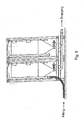
vessel 31 located within asupport frame 81 and being positioned with its longitudinal axis arranged horizontally (Figures 7a and 7b) and with this axis lying vertically (Figure 7c).Vessel 31 has a part spherical shapedupper end 83, a cylindricalmain body section 85 and a lowerconical section 87. At the lowermost end ofconical section 87, the vessel is provided with adischarge valve 89. - Referring to Figure 8 of the accompanying drawings, there is illustrated a container assembly 91 comprising containers 93, each located with a support frame 95. A filling pipe 97 extends into each container via a valve 99 and, where appropriate a branch pipe 101, the container inlet being located in the
upper end 83 of the container. Also extending into the upper end of each container 93 is a compressed air line 103 having valves 105. Any number of containers may be connected in this way with a common material filling pipe and a common material discharge pipe. - At the lower end of each container 93 is a
discharge valve 89 having connected thereto a pipe 107 via, if appropriate, a branch pipe 109. In order to empty a vessel filled via pipe 97, valve 99 is closed,valve 89 is opened and compressed air is fed to the vessel via air line 103. The drill cuttings/oil mixture is forced out of vessel 93 under the pressure of the compressed air and into pipe 107. Due to the conical angle of the conical or hopper section 93 being less than a certain value, the material flow out of container 93 is of the type known as mass flow and results in all of the material exiting uniformly out of the container. - Referring to Figure 9 of the accompanying drawings, there is illustrated in both elevation (Figure 9a) and in plan (Figure 9b) a supply boat which is fitted with large conveying
vessels 111 which extend through the deck of the boat. This arrangement can hold up to thousand tons of drill cuttings/oil mixture and this mixture can be pumped pneumatically from the tanks onto shore based storage containers. The conveyingvessels 111 have a cone angle such that mass flow occurs and they work in a similar way to the assembly of Figure 8. - Referring to Figure 10 of the accompanying drawings, there is illustrated another embodiment of a supply boat illustrated in elevation (Figure 10a) and in plan (Figure 10b). In this case the boat is for conveying
containers 113 which fit within the envelope of a 20ft ISO container frame. - The use of ISO container vessels enables supply boats to be used in substantially unmodified form. Methods- of the present invention involving the use of ISO container vessels may be operated in a different way.
- In one embodiment in accordance with the present invention, a number of empty ISO container vessels is lifted onto the drilling rig by the rig crane. The vessels are stood on end on support frames incorporating the discharge piping and they are assembled into a line of storage vessels each of which can store about twenty tons of cuttings/oil. A pressurised vessel 5 (see Figure 1) is used to transfer the cuttings/oil from screens or centrifuges into the ISO conveying vessels. These vessels are then used to transfer the stored contents onto the supply boat as described above in connection with Figure 1.
- An advantage of this method is that there is a buffer storage on the rig so that drilling can occur when the supply boat is not present. Furthermore transfer rates from the rig are much higher than is possible if a standard pneumatic conveyor system (such as the Clyde system) is used alone. In addition hose sizes can be minimised.
- An alternative embodiment making use of the ISO container vessels involves the use of these vessels on the supplied boat. Thirty or forty of these vessels may be stood on end and rafted together to form a stable structure into which 400 or 500 tons of cuttings can be conveyed, as illustrated in Figure 10. When the vessel returns to port, the contents of the container vessels may be pneumatically transferred ashore. Alternatively, the tanks may be lifted off by cranes, turned horizontal and loaded onto standard ISO container road vehicles. If appropriate they could also be stacked on the quay side in the same way that containers are currently stacked. When the containers are received at the processing plant they are stood on end and used as conveying vessels to transfer the cuttings/oil into their destination.
- In a further embodiment in accordance with the present invention the drill cuttings/oil mixture is stored in large volumes in the legs of semi-submersible oil rigs or drilling platforms. The legs are typically 15m diameter. Pressurised vessels located in the legs and operating on the same principles as described above will store the cuttings/oil mixture and then be used as pneumatic conveying vessels to transfer the material onto the supply boat.
- With some drill cuttings, it may be necessary or desirable to use low friction linings within the pressure vessels. Such linings may be used in conjunction with the use of the mass flow cone angle, as described above, to aid discharge of the drill cuttings from the internal surfaces of the pressure vessels.
Claims (6)
- An apparatus for pneumatically conveying drilling cuttings across the platform of an oil rig, characterized in having
a pressure vessel (5) located on the platform of the oil rig, wherein the pressure vessel is loaded with screened drill cuttings, wherein the pressure vessel includes an upper material inlet and a lower material outlet and
means for supplying compressed air to the interior of the pressure vessel (5);
a second vessel (11) for receiving the conveyed drilling cuttings, wherein the second vessel includes a material inlet, a conical lower portion (15) and at the lowermost point of this portion there is a valve (17) whereby the conveyed drilling cuttings may be discharged from the second vessel; and,
a pipe (7) connecting the outlet of the pressure vessel (5) with the inlet of the second vessel (11). - The apparatus of claim 1, further characterized in that the pressure vessel (5), has a lower conical portion defining a cone angle selected to achieve mass flow of said drill cuttings in said first vessel.
- The apparatus of claims 1 or 2, further characterized in that the second vessel is mounted within a ISO container sized support frame.
- The apparatus of claims 1, 2 or 3, further including
a third vessel for receiving the conveyed drilling cuttings, where in the third vessel includes a material inlet, a conical lower portion and at the lowermost point of this portion there is a valve whereby conveyed drilling cuttings may be discharged from the third vessel; and
a pipe connecting the valve at the lowermost point of the second vessel with the material inlet of the third vessel. - The apparatus of claim 4, further characterized in that the third vessel is mounted within a ISO container sized support frame.
- The apparatus of claims 4 or 5, wherein the third vessel is located on a supply boat.
Applications Claiming Priority (4)
| Application Number | Priority Date | Filing Date | Title |
|---|---|---|---|
| GBGB9913909.9A GB9913909D0 (en) | 1999-06-16 | 1999-06-16 | Pneumatic conveying |
| GB9913909 | 1999-06-16 | ||
| EP00940494A EP1187783B1 (en) | 1999-06-16 | 2000-06-14 | Pneumatic conveying |
| EP03075004A EP1321395B1 (en) | 1999-06-16 | 2000-06-14 | Pneumatic conveying |
Related Parent Applications (1)
| Application Number | Title | Priority Date | Filing Date |
|---|---|---|---|
| EP03075004A Division EP1321395B1 (en) | 1999-06-16 | 2000-06-14 | Pneumatic conveying |
Publications (2)
| Publication Number | Publication Date |
|---|---|
| EP1541507A1 EP1541507A1 (en) | 2005-06-15 |
| EP1541507B1 true EP1541507B1 (en) | 2006-03-29 |
Family
ID=10855387
Family Applications (3)
| Application Number | Title | Priority Date | Filing Date |
|---|---|---|---|
| EP00940494A Expired - Lifetime EP1187783B1 (en) | 1999-06-16 | 2000-06-14 | Pneumatic conveying |
| EP05005350A Expired - Lifetime EP1541507B1 (en) | 1999-06-16 | 2000-06-14 | Pneumatic conveying |
| EP03075004A Expired - Lifetime EP1321395B1 (en) | 1999-06-16 | 2000-06-14 | Pneumatic conveying |
Family Applications Before (1)
| Application Number | Title | Priority Date | Filing Date |
|---|---|---|---|
| EP00940494A Expired - Lifetime EP1187783B1 (en) | 1999-06-16 | 2000-06-14 | Pneumatic conveying |
Family Applications After (1)
| Application Number | Title | Priority Date | Filing Date |
|---|---|---|---|
| EP03075004A Expired - Lifetime EP1321395B1 (en) | 1999-06-16 | 2000-06-14 | Pneumatic conveying |
Country Status (18)
| Country | Link |
|---|---|
| US (8) | US6709217B1 (en) |
| EP (3) | EP1187783B1 (en) |
| JP (2) | JP2003502242A (en) |
| KR (1) | KR100604090B1 (en) |
| CN (1) | CN1201986C (en) |
| AT (3) | ATE321715T1 (en) |
| AU (1) | AU778008B2 (en) |
| BR (1) | BR0011663B1 (en) |
| CA (1) | CA2374583C (en) |
| DE (3) | DE60027058T2 (en) |
| DK (3) | DK1321395T3 (en) |
| EA (2) | EA003121B1 (en) |
| ES (2) | ES2262127T3 (en) |
| GB (1) | GB9913909D0 (en) |
| MX (1) | MXPA01012950A (en) |
| NO (2) | NO319954B1 (en) |
| WO (1) | WO2000076889A1 (en) |
| ZA (1) | ZA200110098B (en) |
Families Citing this family (50)
| Publication number | Priority date | Publication date | Assignee | Title |
|---|---|---|---|---|
| GB9901838D0 (en) * | 1999-01-28 | 1999-03-17 | Halliburton Energy Serv Inc | Slurry treatment |
| GB9913909D0 (en) * | 1999-06-16 | 1999-08-18 | Clyde Pneumatic Conveying Limi | Pneumatic conveying |
| GB0121353D0 (en) * | 2001-09-04 | 2001-10-24 | Rig Technology Ltd | Improvements in or relating to transport of waste materials |
| GB0208728D0 (en) | 2002-04-17 | 2002-05-29 | Clyde Blowers Ltd | Conveying device |
| SG152055A1 (en) * | 2002-10-10 | 2009-05-29 | Singapore Technologies Marine | A method and apparatus for a replenishment at sea system |
| GB2423781B (en) * | 2003-03-19 | 2007-03-28 | Varco Int | Apparatus and method for moving drilled cuttings |
| US7493969B2 (en) * | 2003-03-19 | 2009-02-24 | Varco I/P, Inc. | Drill cuttings conveyance systems and methods |
| US6936092B2 (en) * | 2003-03-19 | 2005-08-30 | Varco I/P, Inc. | Positive pressure drilled cuttings movement systems and methods |
| US7278811B1 (en) * | 2003-04-16 | 2007-10-09 | The Heil Company | Land and sea transport system for particulate materials |
| US6953097B2 (en) | 2003-08-01 | 2005-10-11 | Varco I/P, Inc. | Drilling systems |
| PT1718839E (en) * | 2004-01-29 | 2009-07-06 | Gjerdrum As Ing | System tank and output unit for transporting untreated drill cuttings |
| GB0409318D0 (en) * | 2004-04-27 | 2004-06-02 | Its Drilling Services Ltd | Material transportation apparatus and method |
| EA013456B1 (en) * | 2004-06-22 | 2010-04-30 | ВАРКО Ай/Пи, ИНК. | A method for processing drill cuttings and apparatus therefor |
| GB0519450D0 (en) * | 2005-09-23 | 2005-11-02 | Benhar Systems Ltd | Drill cuttings storage and conveying |
| US7753126B2 (en) * | 2005-11-26 | 2010-07-13 | Reddoch Sr Jeffrey A | Method and apparatus for vacuum collecting and gravity depositing drill cuttings |
| US7971657B2 (en) * | 2005-12-13 | 2011-07-05 | Baker Hughes Incorporated | Drill cuttings transfer system and related methods |
| AU2007234766A1 (en) * | 2006-04-05 | 2007-10-18 | Baker Hughes Incorporated | Drill cuttings transfer system and related methods |
| US8607894B2 (en) * | 2006-12-08 | 2013-12-17 | M-I Llc | Offshore thermal treatment of drill cuttings fed from a bulk transfer system |
| US8074738B2 (en) * | 2006-12-08 | 2011-12-13 | M-I L.L.C. | Offshore thermal treatment of drill cuttings fed from a bulk transfer system |
| US8741072B2 (en) * | 2007-01-31 | 2014-06-03 | M-I Llc | Use of cuttings vessel for tank cleaning |
| US7828084B2 (en) * | 2007-01-31 | 2010-11-09 | M-I L.L.C. | Use of cuttings tank for slurrification on drilling rig |
| US7770665B2 (en) * | 2007-01-31 | 2010-08-10 | M-I Llc | Use of cuttings tank for in-transit slurrification |
| US8316963B2 (en) * | 2007-01-31 | 2012-11-27 | M-I Llc | Cuttings processing system |
| US7730966B2 (en) * | 2007-01-31 | 2010-06-08 | M-I L.L.C. | High density slurry |
| US8083935B2 (en) * | 2007-01-31 | 2011-12-27 | M-I Llc | Cuttings vessels for recycling oil based mud and water |
| US8074509B2 (en) * | 2007-02-21 | 2011-12-13 | M-I Llc | Wellbore monitor |
| WO2008131385A1 (en) | 2007-04-23 | 2008-10-30 | M-I Llc | Rig storage system |
| US8215028B2 (en) | 2007-05-16 | 2012-07-10 | M-I L.L.C. | Slurrification process |
| WO2009015184A2 (en) * | 2007-07-24 | 2009-01-29 | M-I Llc | Feed hopper for positive displacement pumps |
| DK2207747T3 (en) * | 2007-10-24 | 2013-07-01 | Mi Llc | Boat installation frame for transport tanks |
| EA021969B1 (en) * | 2008-09-05 | 2015-10-30 | Шлюмбергер Норге Ас | System and method for proppant transfer |
| US8141645B2 (en) * | 2009-01-15 | 2012-03-27 | Single Buoy Moorings, Inc. | Offshore gas recovery |
| EA024657B1 (en) | 2009-01-27 | 2016-10-31 | Шлюмбергер Норге Ас | Methods for granular scavenger material transfer |
| EP2228294A1 (en) * | 2009-03-09 | 2010-09-15 | RAM LNG Holdings Limited | Vessel for transport of liquefied natural gas |
| CN102388200A (en) * | 2009-04-06 | 2012-03-21 | 瑞士单浮筒系泊公司 | Use of underground gas storage to provide a flow assurance buffer between interlinked processing units |
| DK2284106T3 (en) * | 2009-08-10 | 2012-03-05 | Peters Claudius Projects Gmbh | Deep storage storage facility |
| US20140014214A1 (en) * | 2009-09-25 | 2014-01-16 | Jan Thore Eia | Multiple Process Service Vessel |
| AU2010303478A1 (en) | 2009-10-06 | 2012-05-03 | M-I L.L.C. | Method for hydrocarbon removal and recovery from drill cuttings |
| AU2010343033B2 (en) * | 2010-01-20 | 2015-10-08 | Pentair Flow Control Pacific Pty Ltd | Storage apparatus |
| WO2012068352A2 (en) * | 2010-11-17 | 2012-05-24 | Danny Ness | Mixing tank and method of use |
| CN103748313A (en) | 2011-04-29 | 2014-04-23 | M-I有限公司 | Drilling waste treatment |
| US8915271B2 (en) * | 2011-12-20 | 2014-12-23 | Xuejie Liu | System and method for fluids transfer between ship and storage tank |
| EP2925952B1 (en) | 2012-11-29 | 2020-01-01 | M-I Llc | Vapor displacement method for hydrocarbon removal and recovery from drill cuttings |
| US10358882B2 (en) * | 2013-11-26 | 2019-07-23 | Mantovani & Vicentini S.R.L | Continuous vacuum transport system and method |
| US9689218B1 (en) | 2014-03-04 | 2017-06-27 | Thomas McDaniel | Drill cuttings diverter system |
| WO2016055068A1 (en) * | 2014-10-07 | 2016-04-14 | Mhi Vestas Offshore Wind A/S | Apparatus and method for removing equipment parts from a platform of a wind turbine generator, and method for filling a fuel tank on said platform |
| JP6126323B2 (en) * | 2015-03-04 | 2017-05-10 | 芝海株式会社 | Handling equipment |
| DE102017207035A1 (en) | 2017-04-26 | 2018-10-31 | Thyssenkrupp Ag | Process and device for producing a granulate |
| CN107740931A (en) * | 2017-08-15 | 2018-02-27 | 舟山长宏国际船舶修造有限公司 | A kind of full ship kinetic energy fast supply system for ship construction |
| CN111520557B (en) * | 2020-04-28 | 2022-04-01 | 广船国际有限公司 | Three-way joint, cargo oil conveying system, use method of cargo oil conveying system and ship |
Family Cites Families (203)
| Publication number | Priority date | Publication date | Assignee | Title |
|---|---|---|---|---|
| US1309671A (en) | 1919-07-15 | Concrete mixing | ||
| US599702A (en) | 1898-03-01 | Pneumatic distributing system for liquids | ||
| US1127660A (en) | 1911-01-23 | 1915-02-09 | Concrete Mixing And Conveying Company | Method of and apparatus for transporting and treating concrete. |
| US1347358A (en) | 1919-02-28 | 1920-07-20 | Adams Samuel Henry | Fluid or air direct-pressure lifting and forcing apparatus for solids and semisolids |
| US1782681A (en) | 1927-01-12 | 1930-11-25 | Leonard R Foss | Feed gun |
| FR642010A (en) | 1927-10-06 | 1928-08-17 | Advanced device for pressurized ejection and transport of concrete by compressed air | |
| GB419756A (en) | 1932-05-27 | 1934-11-19 | Joseph Elliot Kennedy | Improvements in pneumatic transport systems |
| US1983185A (en) | 1933-10-14 | 1934-12-04 | Acmeline Mfg Company | Filling top for sprayer tanks |
| US2073982A (en) | 1934-02-09 | 1937-03-16 | Lcl Corp | Container and container car |
| US2115023A (en) | 1935-03-18 | 1938-04-26 | Reconstruction Finance Corp | Means for transporting material |
| US2380651A (en) | 1943-02-11 | 1945-07-31 | Yeomans Brothers Co | Pneumatic ejector |
| GB671111A (en) | 1948-11-26 | 1952-04-30 | Cie Parisienne Outil Air Compr | Improved means for transporting or distributing concrete or the like |
| FR979085A (en) | 1948-11-26 | 1951-04-23 | Cie Parisienne Outil Air Compr | Carrier or distributor of concrete or other similar materials |
| US2612297A (en) | 1950-04-25 | 1952-09-30 | Jay G Bain | Catchup dispenser |
| US2599235A (en) | 1950-09-07 | 1952-06-03 | Prehy Co Inc | Concrete conveying apparatus |
| US2753220A (en) | 1953-03-27 | 1956-07-03 | Maxwell F Kemper | Apparatus for controlling the application of concrete in the lining of tunnels |
| DE1001185B (en) | 1955-02-17 | 1957-01-17 | Friedrich Wilh Schwing | Device for pneumatic conveying of pulpy or plastic masses, preferably concrete |
| GB779479A (en) | 1955-02-17 | 1957-07-24 | Schwing Friedrich Wilh | Means for conveying pulpy or plastic materials |
| GB770377A (en) | 1955-04-26 | 1957-03-20 | Cie Parisienne Outil Air Compr | Improvements in or relating to methods of and means for conveying and distributing concrete and like pasty materials |
| DE1013222B (en) | 1955-05-23 | 1957-08-01 | Schwing Friedrich Wilh | Device for pneumatic conveying of pulpy or plastic masses, preferably concrete |
| FR1154954A (en) | 1955-12-16 | 1958-04-18 | Pneumatic concrete transport installation | |
| DE1128809B (en) | 1956-01-19 | 1962-04-26 | Friedrich Wilh Schwing | Device for pneumatic conveying of pulpy or plastic masses, preferably concrete |
| DE1031215B (en) | 1956-01-19 | 1958-05-29 | Friedrich Wilh Schwing | Device for pneumatic conveying of pulpy or plastic masses, preferably concrete |
| FR1184961A (en) | 1957-10-22 | 1959-07-28 | Device intended to ensure the regularity of evacuation of powdery, pasty, and similar substances in containers or other | |
| FR1230526A (en) | 1959-03-21 | 1960-09-16 | Siderurgie Fse Inst Rech | Automatic regulation device of a pressurized powder dispenser |
| FR1285957A (en) | 1961-01-16 | 1962-03-02 | Feeder for transporting concrete under pressure | |
| FR1295567A (en) | 1961-04-28 | 1962-06-08 | Pneumatic concrete pulsator | |
| US3136456A (en) | 1961-06-02 | 1964-06-09 | William A Sherbondy | Caulking mechanism |
| DE1152947B (en) | 1961-12-19 | 1963-08-14 | Heinrich Braun Angott Dipl Ing | Compressed air delivery device with a pressure vessel for dusty or grainy conveyed goods that tend to stick together and stick |
| ES285697A1 (en) | 1962-03-05 | 1963-08-01 | Pneumatisk Transport A B | A method of introducing a suspension of cement in a hole in rock or similar (Machine-translation by Google Translate, not legally binding) |
| FR1382944A (en) | 1963-07-23 | 1964-12-24 | Apparatus for moving and transporting fluid or powdery materials | |
| US3195960A (en) | 1963-07-23 | 1965-07-20 | Trythall William John Courtney | Material handling systems |
| US3281019A (en) | 1963-10-22 | 1966-10-25 | John P Curry | Material dispenser for packing a column of narrow tubing |
| US3272393A (en) | 1963-12-13 | 1966-09-13 | John O Roeser | Apparatus and method for precision metering and deposit of viscous materials |
| FR1396528A (en) | 1964-03-13 | 1965-04-23 | Compressed air insufflator device | |
| US3258176A (en) | 1964-09-24 | 1966-06-28 | Zenith Radio Corp | Pneumatic glue dispenser |
| US3363404A (en) | 1964-10-06 | 1968-01-16 | Swaco Inc | Mud degassers |
| US3288537A (en) | 1965-07-26 | 1966-11-29 | Pullman Inc | Means for handling material |
| US3375043A (en) | 1966-01-20 | 1968-03-26 | Union Tank Car Co | Methods of and means for effecting discharge of materials from tank cars |
| FR1477357A (en) | 1966-04-26 | 1967-04-14 | Improved device to facilitate the flow of granular materials | |
| US3362487A (en) | 1966-05-03 | 1968-01-09 | Swaco Inc | Control for a hydraulically actuated choke in a drilling mud flow line |
| US3369716A (en) | 1966-06-13 | 1968-02-20 | Capvac Ind Inc | Hopper means having hyperbolic side walls |
| DE1277119B (en) | 1966-08-06 | 1968-09-05 | Bjarne Sem | Device for pneumatic conveying of coarse or difficult-to-flow masses |
| GB1151246A (en) | 1966-11-14 | 1969-05-07 | William John Courtney Trythall | Improvements in or relating to Pneumatic Material Handling Systems |
| DE1630025A1 (en) | 1967-06-03 | 1970-07-23 | Huder Muehlenbau Maschinenfabr | Device for transporting bulk goods |
| GB1172575A (en) | 1967-06-08 | 1969-12-03 | Bjarne Sem | Apparatus for Conveying Granular or Viscous Material by Means of Compressed Air |
| DE1531979A1 (en) | 1967-07-28 | 1972-03-02 | Wilhelm Hermanns | Container for the transport of bulk goods |
| GB1240457A (en) | 1967-10-24 | 1971-07-28 | Trythall Design And Dev Ltd | Improvements in or relating to pneumatic material handling apparatus |
| GB1216507A (en) | 1967-12-18 | 1970-12-23 | Capvac Ind Inc | A material transfer vessel |
| GB1216506A (en) | 1967-12-18 | 1970-12-23 | Capvac Ind Inc | A system for moving bulk material |
| DE1296097B (en) | 1968-01-12 | 1969-05-22 | Capvac Ind Inc | Container for a pneumatically operating conveyor device |
| FR1551795A (en) | 1968-01-25 | 1968-12-27 | ||
| DE1807295A1 (en) | 1968-11-06 | 1970-05-21 | Hermanns Wilhelm | Method and device for emptying containers filled with loose material, liquids or pastes |
| US3955717A (en) | 1969-08-06 | 1976-05-11 | Landau Richard E | Methods and apparatus for flowing archable materials |
| GB1353158A (en) | 1970-11-18 | 1974-05-15 | Rowan Investments Ltd | Discharge of containers and pressure vessels |
| US3797707A (en) | 1971-04-20 | 1974-03-19 | Jenike And Johanson Inc | Bins for storage and flow of bulk solids |
| US3727985A (en) * | 1972-01-03 | 1973-04-17 | Cons Eng Co | Pneumatic conveying apparatus automatically operable successively for weight responsive filling, and for activation, discharging, purging against back pressure, and venting |
| US3809436A (en) | 1972-05-25 | 1974-05-07 | Cpc Eng Corp | Process for conveyance of ash |
| NO129735B (en) | 1972-07-06 | 1974-05-20 | Sem Bjarne | |
| US3811518A (en) | 1972-07-24 | 1974-05-21 | Bus Rx Inc | Method of and apparatus for collecting cuttings from a drilled hole |
| US3788527A (en) | 1973-01-22 | 1974-01-29 | Martin Eng Co | Quick-release aerator for introducing high pressure air into a container to facilitate dispensing |
| DE2328496A1 (en) | 1973-06-05 | 1975-01-02 | Sietam Foerdertech | METHOD AND DEVICE FOR ACCELERATED DOSING OF SCHUETTGUETERS INTO PNEUMATIC CONVEYOR LINES |
| FR2237819A1 (en) | 1973-07-18 | 1975-02-14 | Sem Bjarne | Low press. pneumatic transporter for cement - air injector valves produce vibrations and induce turbulent flow |
| US3921858A (en) | 1973-11-05 | 1975-11-25 | Robert A Bemm | Automatic confection decorating system |
| US4024258A (en) * | 1974-05-31 | 1977-05-17 | American Hoechst Corporation | Composition of and method for reducing hypertension with a 1-[1-(indol-3-ylethyl)-piperazin-4-yl]-3-substituted urea |
| US3964557A (en) | 1974-10-11 | 1976-06-22 | Gulf Research & Development Company | Treatment of weighted drilling mud |
| GB1551222A (en) | 1975-04-25 | 1979-08-30 | Macawber Eng Ltd | Material handling system |
| AT344088B (en) | 1975-04-30 | 1978-07-10 | Spitzer Silo Fahrzeugwerk Kg | METHOD AND DEVICE FOR EJECTING PNEUMATICALLY FORWARDABLE BULK MATERIAL FROM A OUTLET FUNNEL OF A PRESSURE LOADED SILO HOLDER |
| LU72387A1 (en) | 1975-04-30 | 1975-08-26 | ||
| GB1545494A (en) | 1975-06-09 | 1979-05-10 | Macawber Eng Ltd | Pneumatic conveying apparatus |
| US4036099A (en) | 1975-07-25 | 1977-07-19 | Occidental Oil Shale, Inc. | Method of loading blast hole with explosive |
| US4113151A (en) | 1975-11-12 | 1978-09-12 | Valley Hydro-Luft, Inc. | Dispensing gun |
| US4101175A (en) | 1975-12-24 | 1978-07-18 | Acf Industries, Incorporated | Railway hopper car for unloading ladings which do not readily fluidize |
| US4137935A (en) | 1976-02-11 | 1979-02-06 | Macawber Engineering Limited | Valve assembly |
| GB1539079A (en) * | 1976-02-11 | 1979-01-24 | Macawber Eng Ltd | Valve assembly |
| GB1595065A (en) | 1977-01-28 | 1981-08-05 | Exxon Research Engineering Co | Hopper |
| GB1564311A (en) | 1977-02-14 | 1980-04-10 | Macawber Eng Ltd | Conveying of bulk materials |
| US4098541A (en) | 1977-03-24 | 1978-07-04 | Camille Cote | Apparatus for evacuating manure |
| US4174868A (en) | 1977-08-25 | 1979-11-20 | Nardo John M De | Apparatus for pneumatically applying material to an object |
| DE2755671C2 (en) | 1977-12-14 | 1982-10-14 | Filterwerk Mann & Hummel Gmbh, 7140 Ludwigsburg | Multi-point conveying system for the pneumatic suction conveying of powdery material from a storage container to several conveying stations |
| US4175039A (en) | 1978-01-30 | 1979-11-20 | Fisher Johnny D | Washer/separator system for drilling cuttings in water environment oil wells |
| US4209381A (en) | 1978-02-02 | 1980-06-24 | Mobil Oil Corporation | Method and apparatus for treating drill cuttings at an onsite location |
| US4242146A (en) | 1979-01-08 | 1980-12-30 | Mobil Oil Corporation | Method for treating oil-contaminated drill cuttings |
| DE2922453A1 (en) | 1979-06-01 | 1980-12-04 | Waeschle Maschf Gmbh | Pressure vessel for dispensing bulk materials - has internal overflow pipe slid vertically by external adjusting mechanism |
| GB2068868B (en) | 1980-02-09 | 1984-02-15 | Macawber Eng Ltd | Pneumatic conveying of bulk material |
| DE3012065A1 (en) | 1980-03-28 | 1981-10-22 | Spitzer Silo- Fahrzeugwerk Kg, 6950 Mosbach | Bulk material vessel pneumatic discharge equipment - has separate supply system for top nozzles and bottom nozzles |
| GB2089330B (en) * | 1980-12-11 | 1985-02-27 | British Gas Corp | Discharging storage containers |
| EP0060135B1 (en) | 1981-03-09 | 1985-09-11 | Macawber Engineering Limited | Conveying apparatus |
| DE3270953D1 (en) | 1981-03-09 | 1986-06-12 | Macawber Eng Ltd | Method and apparatus for conveying particulate material |
| WO1982003065A1 (en) | 1981-03-10 | 1982-09-16 | Snowdon Brian | Conveying systems |
| US4451184A (en) | 1981-06-12 | 1984-05-29 | Chevron Research Company | Apparatus and method for feeding pulverized hydrocarbonaceous solids into a high pressure reactor |
| US4439069A (en) | 1981-12-11 | 1984-03-27 | Mobil Oil Corporation | Method and apparatus for disposing of drill cuttings at an offshore location |
| DE3230927C2 (en) * | 1982-08-20 | 1985-02-07 | Deutsche Texaco Ag, 2000 Hamburg | Procedure for loading and / or handling environmentally unfriendly materials in the operation of offshore oil fields in shallow water and mud flats and artificial islands suitable for this purpose |
| US4526121A (en) * | 1982-08-30 | 1985-07-02 | Hitachi Shipbuilding & Engineering Co., Ltd. | Ship for treating coal slurry |
| DE3233099A1 (en) | 1982-09-07 | 1984-03-08 | Karl Hamacher GmbH, 4630 Bochum | Feeding station for feeding pourable conveying material into the pipe of a pneumatic conveyor system by means of compressed air |
| DE3303542A1 (en) | 1983-02-03 | 1984-08-16 | Stelma Industrieanlagen GmbH & Co KG, 4775 Lippetal | Device for feeding and metering pneumatically conveyable powders |
| US4832539A (en) * | 1983-04-20 | 1989-05-23 | The Babcock & Wilcox Company | Distribution of gas entrained particles |
| DE3330561A1 (en) * | 1983-08-24 | 1985-03-07 | Westerwälder Eisenwerk Gerhard GmbH, 5241 Weitefeld | CARGO CONTAINER FOR FLOWABLE SUBSTANCES |
| DE3333433A1 (en) | 1983-09-09 | 1985-03-21 | Maschinenfabrik Karl Brieden & Co, 4630 Bochum | System for dispensing pasty to milky filling and injection material consisting of hydraulic construction materials in underground operation, preferably for supplying driving works in mining and tunnel construction |
| DE3410244A1 (en) | 1983-09-09 | 1985-10-03 | Maschinenfabrik Karl Brieden & Co, 4630 Bochum | Plant for preparing pasty to milky filling and injection material from hydraulic construction materials in underground operation, preferaby for supplying roadway drivages in mining and tunnelling |
| GB2147397A (en) | 1983-09-28 | 1985-05-09 | Macawber Eng Ltd | Feeding particulate material |
| US4699548A (en) | 1983-12-19 | 1987-10-13 | Howden Environmental Systems, Inc. | Slurry conveying system |
| DE3579249D1 (en) | 1984-05-03 | 1990-09-27 | Aerosol Service Ag | DRIVING DEVICE FOR A HIGH-VISCOSITY FILLED DISCHARGE TANK. |
| US4645608A (en) | 1984-10-10 | 1987-02-24 | Sun Drilling Products, Corp. | Method of treating oil contaminated cuttings |
| DE3439251A1 (en) | 1984-10-26 | 1986-04-30 | KBI Klöckner-Becorit Industrietechnik GmbH, 4224 Hünxe | Apparatus for feeding bulk material to a pneumatic conveying pipe |
| US4913245A (en) | 1984-12-03 | 1990-04-03 | Atlantic Richfield Company | Wellbore drilling cuttings treatment |
| US4683963A (en) | 1985-04-19 | 1987-08-04 | Atlantic Richfield Company | Drilling cuttings treatment |
| US4662799A (en) | 1985-05-17 | 1987-05-05 | Fuller Company | Apparatus and process for pneumatically conveying particulate material |
| GB8528508D0 (en) | 1985-11-20 | 1985-12-24 | Macawber Ltd Simon | Material conveying apparatus |
| JPS62141216A (en) * | 1985-12-13 | 1987-06-24 | Nippon Steel Corp | One-point mooring device for oil storage tanker for oil-producing structure in sea |
| US4696353A (en) | 1986-05-16 | 1987-09-29 | W. S. Tyler, Incorporated | Drilling mud cleaning system |
| US4793423A (en) | 1986-10-31 | 1988-12-27 | Shell Western E&P Inc. | Process for treating drilled cuttings |
| US4836302A (en) | 1986-12-03 | 1989-06-06 | Heilhecker Joe K | Apparatus and method for removing and recovering oil and/or other oil-based drilling mud additives from drill cuttings |
| US4747961A (en) | 1986-12-19 | 1988-05-31 | Atlantic Richfield Company | Method and system for treating drill cutting slurries and the like |
| US4834587A (en) | 1987-05-28 | 1989-05-30 | Macawber Engineering, Inc. | Pneumatic conveying system |
| US4823989A (en) | 1987-06-25 | 1989-04-25 | J&L Tank, Inc. | Compartmentalized pneumatic vessel filtering and unloading system |
| US4872949A (en) | 1988-03-08 | 1989-10-10 | Wilwerding Carl M | Process for treatment of drilling mud |
| US4900200A (en) * | 1988-06-22 | 1990-02-13 | Matsui Manufacturing Co., Ltd. | Method for transporting powdered or granular materials by pneumatic force with a transport pipe of smaller diameter relative to particale size |
| US5012957A (en) | 1989-01-27 | 1991-05-07 | Promation Incorporated | Dispenser apparatus |
| US4942929A (en) | 1989-03-13 | 1990-07-24 | Atlantic Richfield Company | Disposal and reclamation of drilling wastes |
| DE4007430A1 (en) | 1990-03-09 | 1991-09-12 | Buehler Gmbh | METHOD FOR CONVEYING PORTIONS FROM GRAINY OR POWDERY PUPULAR GOODS AND DEVICE FOR IMPLEMENTING THE METHOD |
| SU1751121A1 (en) | 1990-03-19 | 1992-07-30 | Всесоюзный научно-исследовательский институт сахарной промышленности | Unit for delivery of strained sediment into pipeline |
| JPH03279117A (en) * | 1990-03-27 | 1991-12-10 | Mitsubishi Heavy Ind Ltd | Force feed device for slurry |
| DE4010676A1 (en) * | 1990-04-03 | 1991-10-10 | Ihlefeld Karl Helmut | Continuous supply of concrete to work place - involves use of pressurised vessel and screw conveyor |
| US5109933A (en) | 1990-08-17 | 1992-05-05 | Atlantic Richfield Company | Drill cuttings disposal method and system |
| US5129469A (en) | 1990-08-17 | 1992-07-14 | Atlantic Richfield Company | Drill cuttings disposal method and system |
| US5728519A (en) * | 1990-11-06 | 1998-03-17 | The United States Of America As Represented By The Department Of Health And Human Services | Assay for virulent revertants of attenuated live vaccines and kits therefor |
| NO175412C (en) | 1990-11-28 | 1994-10-12 | Norske Stats Oljeselskap | Process for treating waste materials for injection into underground formations |
| US5213446A (en) | 1991-01-31 | 1993-05-25 | Union Oil Company Of California | Drilling mud disposal technique |
| US5129468A (en) | 1991-02-01 | 1992-07-14 | Conoco Specialty Products Inc. | Method and apparatus for separating drilling and production fluids |
| JPH089069Y2 (en) * | 1991-02-05 | 1996-03-13 | 川崎重工業株式会社 | Blow-through prevention device for air transport equipment for wet mass |
| US5494381A (en) | 1991-04-11 | 1996-02-27 | The Young Industries, Inc. | Apparatus and method for pneumatically conveying bulk materials |
| US5125540A (en) | 1991-07-02 | 1992-06-30 | Maraven, S.A. | Measuring device and fluid dispenser |
| US5150666A (en) | 1991-11-01 | 1992-09-29 | Ctb, Inc. | Feeding apparatus |
| US5226575A (en) | 1991-11-21 | 1993-07-13 | Scott Faust | Pneumatic mortar dispenser with flex release |
| DE4200502A1 (en) | 1992-01-13 | 1993-07-15 | Henkel Kgaa | IMPROVED DISPOSAL OF CONTAMINATED DRILL SMALL FROM GEOLOGICAL HOLES WITH MINERAL OIL CONTAINING DRILL RINSING SYSTEMS |
| DE4202561A1 (en) | 1992-01-30 | 1993-08-05 | Boehringer Mannheim Gmbh | DEVICE FOR DELIVERING AN ANALYZING LIQUID |
| US5330017A (en) | 1992-04-06 | 1994-07-19 | Profit Production, Inc. | Method of processing drilling mud in earth-boring operations |
| US5226749A (en) | 1992-07-08 | 1993-07-13 | Atlantic Richfield Company | Waste disposal in hydraulically fractured earth formations |
| US5303786A (en) | 1992-09-16 | 1994-04-19 | Atlantic Richfield Company | Earth drilling cuttings processing system |
| US5341882A (en) | 1993-02-10 | 1994-08-30 | Shell Oil Company | Well drilling cuttings disposal |
| US5314265A (en) | 1993-03-17 | 1994-05-24 | Atlantic Richfield Company | Waste disposal in hydraulically fractured earth formations |
| US5339912A (en) | 1993-03-26 | 1994-08-23 | Abb Vetco Gray Inc. | Cuttings disposal system |
| US5454957A (en) | 1993-04-19 | 1995-10-03 | Roff, Jr.; John W. | Closed loop system and method of processing cuttings |
| US5310285A (en) | 1993-05-14 | 1994-05-10 | Northcott T J | Device for reclaiming and disposal of drilling wastes and method of use therefore |
| FR2705252B1 (en) | 1993-05-19 | 1995-07-21 | Bp Chemicals Snc | Process for introducing a solid into a reactor and apparatus. |
| GB2278864B (en) | 1993-06-10 | 1996-07-17 | James Leslie Dallas | System for retrieving waste drilling mud |
| GB2279429B (en) | 1993-06-24 | 1997-03-26 | Macawber Ltd Simon | Valve assembly |
| GB9313026D0 (en) | 1993-06-24 | 1993-08-11 | Macawber Ltd Simon | Sealing device |
| US5445956A (en) * | 1993-08-13 | 1995-08-29 | The Regents Of The University Of California | Recombinant soluble epoxide hydrolase |
| US6213227B1 (en) | 1994-02-17 | 2001-04-10 | M-I, L.L.C. | Oil and gas well cuttings disposal system with continous vacuum operation for sequentially filling disposal tanks |
| US6345672B1 (en) | 1994-02-17 | 2002-02-12 | Gary Dietzen | Method and apparatus for handling and disposal of oil and gas well drill cuttings |
| US5839521A (en) | 1994-02-17 | 1998-11-24 | Dietzen; Gary H. | Oil and gas well cuttings disposal system |
| US5842529A (en) | 1994-02-17 | 1998-12-01 | Dietzen; Gary H. | Oil and gas well cuttings disposal system |
| US6009959A (en) | 1994-02-17 | 2000-01-04 | M-I L.L.C. | Oil and gas well cuttings disposal system with continuous vacuum operation for sequentially filling disposal tanks |
| US6179070B1 (en) | 1994-02-17 | 2001-01-30 | M-I L.L.C. | Vacuum tank for use in handling oil and gas well cuttings |
| US5402857A (en) | 1994-02-17 | 1995-04-04 | Dietzen; Gary H. | Oil and gas well cuttings disposal system |
| US5971084A (en) | 1994-02-17 | 1999-10-26 | M-I L.L.C. | Cuttings tank apparatus |
| US5913372A (en) | 1994-02-17 | 1999-06-22 | M-L, L.L.C. | Oil and gas well cuttings disposal system with continuous vacuum operation for sequentially filling disposal tanks |
| US6179071B1 (en) | 1994-02-17 | 2001-01-30 | M-I L.L.C. | Method and apparatus for handling and disposal of oil and gas well drill cuttings |
| US5542719A (en) | 1994-07-08 | 1996-08-06 | Nordin; Harvey L. | Stationary standby sand spreading unit for roadways |
| DE4427013A1 (en) | 1994-07-29 | 1996-02-01 | Loctite Europa Eeig | Method and device for removing gas bubbles from a viscous liquid to be dispensed |
| US5589603A (en) | 1994-08-22 | 1996-12-31 | Newpark Resources, Inc. | Method and apparatus for the injection disposal of solid and liquid waste materials from the drilling and production of oil and gas wells |
| US5495381A (en) * | 1994-11-22 | 1996-02-27 | Sundstrand Corporation | Protection system for undetected over voltage in an isolated voltage regulator |
| US5618136A (en) | 1995-08-04 | 1997-04-08 | Smoot Co. | Dual blower railcar discharge and conveyor system and method |
| DE19637012A1 (en) | 1995-09-13 | 1997-04-03 | Thyssen Stahl Ag | Jet cartridge with through bore which narrows to form jet |
| US6279471B1 (en) | 1995-09-15 | 2001-08-28 | Jeffrey Reddoch | Drilling fluid recovery defluidization system |
| US5996484A (en) | 1995-09-15 | 1999-12-07 | Reddoch; Jeffrey | Drilling fluid recovery defluidization system |
| US5570749A (en) | 1995-10-05 | 1996-11-05 | Onsite Technology, L.L.C. | Drilling fluid remediation system |
| US5775852A (en) * | 1996-03-15 | 1998-07-07 | Pro Line Systems, Inc. | Apparatus and method for adding dry materials to liquid drilling mud system |
| JP3701976B2 (en) | 1996-05-06 | 2005-10-05 | ジェイ.テレル ウイリアムズ | Continuous belt type drilling mud separation system |
| US5715762A (en) * | 1996-05-29 | 1998-02-10 | Florida Power Corporation | Coal ash disposal system |
| US5686685A (en) | 1996-06-19 | 1997-11-11 | Dyno Nobel Inc. | System for pneumatic delivery of emulsion explosives |
| US5900137A (en) | 1996-06-27 | 1999-05-04 | Homan; Edwin Daryl | Apparatus and method for separating components in well fluids |
| US6531506B1 (en) * | 1996-08-13 | 2003-03-11 | Regents Of The University Of California | Inhibitors of epoxide hydrolases for the treatment of hypertension |
| UA55397C2 (en) | 1996-09-05 | 2003-04-15 | Йоханнес Мьоллер Гамбург Інженірінг Гмбх | Process for controlling an installation for transporting powdered material into a transport line |
| AU5188098A (en) * | 1996-10-22 | 1998-05-15 | Frederic Dietrich | Process and device for pneumatically conveying powdery substances and their use |
| US5816450A (en) | 1996-11-27 | 1998-10-06 | Alexander; David C. | Pneumatic frosting applicator |
| US6152656A (en) * | 1997-06-19 | 2000-11-28 | J. A. Jones Environmental Services Company | Material delivery system |
| US6170580B1 (en) | 1997-07-17 | 2001-01-09 | Jeffery Reddoch | Method and apparatus for collecting, defluidizing and disposing of oil and gas well drill cuttings |
| GB9722367D0 (en) * | 1997-10-24 | 1997-12-17 | Bailey Marshall G | Improvements in and relating to methods and apparatus for the transport and storage of material |
| CH692854A5 (en) * | 1997-11-21 | 2002-11-29 | Gericke Ag | Method for operating a peristaltic and peristaltic for performing the method. |
| JP2866082B1 (en) * | 1998-01-13 | 1999-03-08 | 若築建設株式会社 | Mixing method of injected solidified material and soil in pipes during pneumatic feeding of dredged soil |
| US5964304A (en) | 1998-05-08 | 1999-10-12 | Morrison, Jr.; Sidney Johnson | Method and apparatus for drill cuttings transfer |
| JP2000012796A (en) * | 1998-06-19 | 2000-01-14 | Hitachi Ltd | Semiconductor device, and manufacturing method and apparatus thereof |
| WO2000024844A2 (en) | 1998-10-23 | 2000-05-04 | Baker Hughes Incorporated | Treatments for cuttings from offshore rigs |
| US6367029B1 (en) * | 1998-11-03 | 2002-04-02 | Sun Microsystems, Inc. | File server system tolerant to software and hardware failures |
| DE60009865T2 (en) * | 1999-02-17 | 2005-03-31 | Q'max Solutions Inc., Calgary | METHOD AND DEVICE FOR CLEANING DRILLING SMALL |
| US6802685B1 (en) * | 1999-02-23 | 2004-10-12 | Bernd Federhen | Device and method for inwardly transferring bulk material into a pneumatic conveyor line |
| US6328118B1 (en) | 1999-03-08 | 2001-12-11 | Halliburton Energy Services, Inc. | Apparatus and methods of separation of materials in an under-balanced drilling operation |
| US6234258B1 (en) | 1999-03-08 | 2001-05-22 | Halliburton Energy Services, Inc. | Methods of separation of materials in an under-balanced drilling operation |
| US6440682B1 (en) * | 1999-05-28 | 2002-08-27 | Detroit R&D Inc. | Detection of hypertension using immunoreactive metabolic products |
| GB9913909D0 (en) * | 1999-06-16 | 1999-08-18 | Clyde Pneumatic Conveying Limi | Pneumatic conveying |
| US6443613B1 (en) * | 1999-12-08 | 2002-09-03 | The Maitland Company | Method for transporting and delivering substances |
| US6368029B1 (en) * | 2000-01-24 | 2002-04-09 | D'aquin Gerard E. | Transporting sulfur pellets |
| US6375841B1 (en) * | 2000-02-15 | 2002-04-23 | Inter-Source Recovery Systems, Inc. | System for transporting and separating wet chips and delivering dried chips |
| US6453584B1 (en) | 2000-11-27 | 2002-09-24 | Lynn Allen Buckner | Continuous vacuum, separator, dispensing system |
| US6585115B1 (en) * | 2000-11-28 | 2003-07-01 | Baker Hughes Incorporated | Apparatus and method for transferring dry oil and gas well drill cuttings |
| US6831082B2 (en) * | 2001-06-29 | 2004-12-14 | Boehringer Ingelheim Pharmaceuticals, Inc. | Method of using soluble epoxide hydrolase inhibitors |
| GB0121353D0 (en) * | 2001-09-04 | 2001-10-24 | Rig Technology Ltd | Improvements in or relating to transport of waste materials |
| US6745856B2 (en) * | 2002-07-17 | 2004-06-08 | M-I, L.L.C. | Methods and apparatus for disposing of deleterious materials from a well |
| US6936092B2 (en) * | 2003-03-19 | 2005-08-30 | Varco I/P, Inc. | Positive pressure drilled cuttings movement systems and methods |
| GB2423781B (en) * | 2003-03-19 | 2007-03-28 | Varco Int | Apparatus and method for moving drilled cuttings |
-
1999
- 1999-06-16 GB GBGB9913909.9A patent/GB9913909D0/en not_active Ceased
-
2000
- 2000-06-14 AT AT05005350T patent/ATE321715T1/en not_active IP Right Cessation
- 2000-06-14 CA CA002374583A patent/CA2374583C/en not_active Expired - Lifetime
- 2000-06-14 JP JP2001503365A patent/JP2003502242A/en not_active Withdrawn
- 2000-06-14 EP EP00940494A patent/EP1187783B1/en not_active Expired - Lifetime
- 2000-06-14 DK DK03075004T patent/DK1321395T3/en active
- 2000-06-14 CN CNB008116830A patent/CN1201986C/en not_active Expired - Lifetime
- 2000-06-14 AT AT03075004T patent/ATE296253T1/en not_active IP Right Cessation
- 2000-06-14 DE DE60027058T patent/DE60027058T2/en not_active Expired - Lifetime
- 2000-06-14 AT AT00940494T patent/ATE250543T1/en not_active IP Right Cessation
- 2000-06-14 ES ES05005350T patent/ES2262127T3/en not_active Expired - Lifetime
- 2000-06-14 US US10/018,124 patent/US6709217B1/en not_active Expired - Lifetime
- 2000-06-14 EP EP05005350A patent/EP1541507B1/en not_active Expired - Lifetime
- 2000-06-14 DK DK05005350T patent/DK1541507T3/en active
- 2000-06-14 AU AU55422/00A patent/AU778008B2/en not_active Expired
- 2000-06-14 DE DE60005512T patent/DE60005512T2/en not_active Expired - Lifetime
- 2000-06-14 EA EA200200027A patent/EA003121B1/en not_active IP Right Cessation
- 2000-06-14 WO PCT/GB2000/002158 patent/WO2000076889A1/en active IP Right Grant
- 2000-06-14 EP EP03075004A patent/EP1321395B1/en not_active Expired - Lifetime
- 2000-06-14 ES ES00940494T patent/ES2208346T3/en not_active Expired - Lifetime
- 2000-06-14 DK DK00940494T patent/DK1187783T3/en active
- 2000-06-14 MX MXPA01012950A patent/MXPA01012950A/en active IP Right Grant
- 2000-06-14 EA EA200201220A patent/EA004461B1/en not_active IP Right Cessation
- 2000-06-14 DE DE60020407T patent/DE60020407T2/en not_active Expired - Lifetime
- 2000-06-14 KR KR1020017016172A patent/KR100604090B1/en not_active IP Right Cessation
- 2000-06-14 BR BRPI0011663-7A patent/BR0011663B1/en active IP Right Grant
-
2001
- 2001-12-07 ZA ZA200110098A patent/ZA200110098B/en unknown
- 2001-12-14 NO NO20016123A patent/NO319954B1/en not_active IP Right Cessation
-
2003
- 2003-04-02 US US10/405,305 patent/US6702539B2/en not_active Expired - Lifetime
- 2003-04-02 US US10/405,333 patent/US6698989B2/en not_active Expired - Lifetime
- 2003-04-02 US US10/405,334 patent/US6709216B2/en not_active Expired - Lifetime
- 2003-10-27 US US10/694,461 patent/US20040086345A1/en not_active Abandoned
- 2003-10-27 US US10/694,265 patent/US7033124B2/en not_active Expired - Lifetime
- 2003-11-10 US US10/705,086 patent/US7186062B2/en not_active Expired - Lifetime
-
2005
- 2005-06-14 NO NO20052900A patent/NO327942B1/en not_active IP Right Cessation
-
2007
- 2007-02-20 US US11/709,007 patent/US7544018B2/en not_active Expired - Fee Related
- 2007-09-03 JP JP2007227529A patent/JP4620711B2/en not_active Expired - Fee Related
Also Published As
Similar Documents
| Publication | Publication Date | Title |
|---|---|---|
| EP1541507B1 (en) | Pneumatic conveying | |
| US20080073895A1 (en) | Portable storage apparatus for granular material | |
| EP0630838A1 (en) | Particulate material transfer | |
| GB1579342A (en) | Fluent solid material handling means | |
| US5988436A (en) | Discharge device for bulk containers for particulate bulk materials and its use | |
| US4058227A (en) | Pneumatic conveying of granular materials from a nonpressurized environment | |
| WO2003089346A1 (en) | Transportable pressure silo | |
| WO1987004415A1 (en) | Method and system for handling bulk material | |
| JPS5845393B2 (en) | How to handle powder and granular materials on ships | |
| JPS60158083A (en) | Vessel for storing brittle granular material |
Legal Events
| Date | Code | Title | Description |
|---|---|---|---|
| PUAI | Public reference made under article 153(3) epc to a published international application that has entered the european phase |
Free format text: ORIGINAL CODE: 0009012 |
|
| 17P | Request for examination filed |
Effective date: 20050311 |
|
| AC | Divisional application: reference to earlier application |
Ref document number: 1321395 Country of ref document: EP Kind code of ref document: P Ref document number: 1187783 Country of ref document: EP Kind code of ref document: P |
|
| AK | Designated contracting states |
Kind code of ref document: A1 Designated state(s): AT BE CH CY DE DK ES FI FR GB GR IE IT LI LU MC NL PT SE |
|
| GRAP | Despatch of communication of intention to grant a patent |
Free format text: ORIGINAL CODE: EPIDOSNIGR1 |
|
| GRAS | Grant fee paid |
Free format text: ORIGINAL CODE: EPIDOSNIGR3 |
|
| GRAA | (expected) grant |
Free format text: ORIGINAL CODE: 0009210 |
|
| AKX | Designation fees paid |
Designated state(s): AT BE CH CY DE DK ES FI FR GB GR IE IT LI LU MC NL PT SE |
|
| AC | Divisional application: reference to earlier application |
Ref document number: 1187783 Country of ref document: EP Kind code of ref document: P Ref document number: 1321395 Country of ref document: EP Kind code of ref document: P |
|
| AK | Designated contracting states |
Kind code of ref document: B1 Designated state(s): AT BE CH CY DE DK ES FI FR GB GR IE IT LI LU MC NL PT SE |
|
| PG25 | Lapsed in a contracting state [announced via postgrant information from national office to epo] |
Ref country code: AT Free format text: LAPSE BECAUSE OF FAILURE TO SUBMIT A TRANSLATION OF THE DESCRIPTION OR TO PAY THE FEE WITHIN THE PRESCRIBED TIME-LIMIT Effective date: 20060329 Ref country code: LI Free format text: LAPSE BECAUSE OF FAILURE TO SUBMIT A TRANSLATION OF THE DESCRIPTION OR TO PAY THE FEE WITHIN THE PRESCRIBED TIME-LIMIT Effective date: 20060329 Ref country code: CH Free format text: LAPSE BECAUSE OF FAILURE TO SUBMIT A TRANSLATION OF THE DESCRIPTION OR TO PAY THE FEE WITHIN THE PRESCRIBED TIME-LIMIT Effective date: 20060329 Ref country code: BE Free format text: LAPSE BECAUSE OF FAILURE TO SUBMIT A TRANSLATION OF THE DESCRIPTION OR TO PAY THE FEE WITHIN THE PRESCRIBED TIME-LIMIT Effective date: 20060329 |
|
| REG | Reference to a national code |
Ref country code: GB Ref legal event code: FG4D |
|
| REG | Reference to a national code |
Ref country code: CH Ref legal event code: EP |
|
| REG | Reference to a national code |
Ref country code: IE Ref legal event code: FG4D |
|
| REF | Corresponds to: |
Ref document number: 60027058 Country of ref document: DE Date of ref document: 20060518 Kind code of ref document: P |
|
| PG25 | Lapsed in a contracting state [announced via postgrant information from national office to epo] |
Ref country code: SE Free format text: LAPSE BECAUSE OF FAILURE TO SUBMIT A TRANSLATION OF THE DESCRIPTION OR TO PAY THE FEE WITHIN THE PRESCRIBED TIME-LIMIT Effective date: 20060629 |
|
| PG25 | Lapsed in a contracting state [announced via postgrant information from national office to epo] |
Ref country code: MC Free format text: LAPSE BECAUSE OF NON-PAYMENT OF DUE FEES Effective date: 20060630 |
|
| REG | Reference to a national code |
Ref country code: DK Ref legal event code: T3 |
|
| PG25 | Lapsed in a contracting state [announced via postgrant information from national office to epo] |
Ref country code: PT Free format text: LAPSE BECAUSE OF FAILURE TO SUBMIT A TRANSLATION OF THE DESCRIPTION OR TO PAY THE FEE WITHIN THE PRESCRIBED TIME-LIMIT Effective date: 20060829 |
|
| REG | Reference to a national code |
Ref country code: CH Ref legal event code: PL |
|
| REG | Reference to a national code |
Ref country code: ES Ref legal event code: FG2A Ref document number: 2262127 Country of ref document: ES Kind code of ref document: T3 |
|
| PLBE | No opposition filed within time limit |
Free format text: ORIGINAL CODE: 0009261 |
|
| STAA | Information on the status of an ep patent application or granted ep patent |
Free format text: STATUS: NO OPPOSITION FILED WITHIN TIME LIMIT |
|
| 26N | No opposition filed |
Effective date: 20070102 |
|
| EN | Fr: translation not filed | ||
| PG25 | Lapsed in a contracting state [announced via postgrant information from national office to epo] |
Ref country code: GR Free format text: LAPSE BECAUSE OF FAILURE TO SUBMIT A TRANSLATION OF THE DESCRIPTION OR TO PAY THE FEE WITHIN THE PRESCRIBED TIME-LIMIT Effective date: 20060630 Ref country code: FR Free format text: LAPSE BECAUSE OF FAILURE TO SUBMIT A TRANSLATION OF THE DESCRIPTION OR TO PAY THE FEE WITHIN THE PRESCRIBED TIME-LIMIT Effective date: 20070309 |
|
| PG25 | Lapsed in a contracting state [announced via postgrant information from national office to epo] |
Ref country code: FI Free format text: LAPSE BECAUSE OF FAILURE TO SUBMIT A TRANSLATION OF THE DESCRIPTION OR TO PAY THE FEE WITHIN THE PRESCRIBED TIME-LIMIT Effective date: 20060329 |
|
| PG25 | Lapsed in a contracting state [announced via postgrant information from national office to epo] |
Ref country code: LU Free format text: LAPSE BECAUSE OF NON-PAYMENT OF DUE FEES Effective date: 20060614 |
|
| PG25 | Lapsed in a contracting state [announced via postgrant information from national office to epo] |
Ref country code: FR Free format text: LAPSE BECAUSE OF FAILURE TO SUBMIT A TRANSLATION OF THE DESCRIPTION OR TO PAY THE FEE WITHIN THE PRESCRIBED TIME-LIMIT Effective date: 20060329 Ref country code: CY Free format text: LAPSE BECAUSE OF FAILURE TO SUBMIT A TRANSLATION OF THE DESCRIPTION OR TO PAY THE FEE WITHIN THE PRESCRIBED TIME-LIMIT Effective date: 20060329 |
|
| PGFP | Annual fee paid to national office [announced via postgrant information from national office to epo] |
Ref country code: DE Payment date: 20160607 Year of fee payment: 17 |
|
| REG | Reference to a national code |
Ref country code: DE Ref legal event code: R119 Ref document number: 60027058 Country of ref document: DE |
|
| PG25 | Lapsed in a contracting state [announced via postgrant information from national office to epo] |
Ref country code: DE Free format text: LAPSE BECAUSE OF NON-PAYMENT OF DUE FEES Effective date: 20180103 |
|
| PGFP | Annual fee paid to national office [announced via postgrant information from national office to epo] |
Ref country code: NL Payment date: 20190612 Year of fee payment: 20 Ref country code: IT Payment date: 20190620 Year of fee payment: 20 Ref country code: IE Payment date: 20190610 Year of fee payment: 20 Ref country code: DK Payment date: 20190613 Year of fee payment: 20 |
|
| PGFP | Annual fee paid to national office [announced via postgrant information from national office to epo] |
Ref country code: GB Payment date: 20190612 Year of fee payment: 20 Ref country code: ES Payment date: 20190701 Year of fee payment: 20 |
|
| REG | Reference to a national code |
Ref country code: DK Ref legal event code: EUP Expiry date: 20200614 |
|
| REG | Reference to a national code |
Ref country code: NL Ref legal event code: MK Effective date: 20200613 |
|
| REG | Reference to a national code |
Ref country code: GB Ref legal event code: PE20 Expiry date: 20200613 |
|
| REG | Reference to a national code |
Ref country code: IE Ref legal event code: MK9A |
|
| PG25 | Lapsed in a contracting state [announced via postgrant information from national office to epo] |
Ref country code: GB Free format text: LAPSE BECAUSE OF EXPIRATION OF PROTECTION Effective date: 20200613 |
|
| PG25 | Lapsed in a contracting state [announced via postgrant information from national office to epo] |
Ref country code: IE Free format text: LAPSE BECAUSE OF EXPIRATION OF PROTECTION Effective date: 20200614 |
|
| REG | Reference to a national code |
Ref country code: ES Ref legal event code: FD2A Effective date: 20201202 |
|
| PG25 | Lapsed in a contracting state [announced via postgrant information from national office to epo] |
Ref country code: ES Free format text: LAPSE BECAUSE OF EXPIRATION OF PROTECTION Effective date: 20200615 |