EP1541402A2 - Hydraulisches Achsgetriebe und Fahrzeug mit solchem Achsgetriebe - Google Patents
Hydraulisches Achsgetriebe und Fahrzeug mit solchem Achsgetriebe Download PDFInfo
- Publication number
- EP1541402A2 EP1541402A2 EP04029139A EP04029139A EP1541402A2 EP 1541402 A2 EP1541402 A2 EP 1541402A2 EP 04029139 A EP04029139 A EP 04029139A EP 04029139 A EP04029139 A EP 04029139A EP 1541402 A2 EP1541402 A2 EP 1541402A2
- Authority
- EP
- European Patent Office
- Prior art keywords
- hydraulic
- vehicle
- motor
- transaxle
- housing
- Prior art date
- Legal status (The legal status is an assumption and is not a legal conclusion. Google has not performed a legal analysis and makes no representation as to the accuracy of the status listed.)
- Granted
Links
Images


Classifications
-
- B—PERFORMING OPERATIONS; TRANSPORTING
- B60—VEHICLES IN GENERAL
- B60K—ARRANGEMENT OR MOUNTING OF PROPULSION UNITS OR OF TRANSMISSIONS IN VEHICLES; ARRANGEMENT OR MOUNTING OF PLURAL DIVERSE PRIME-MOVERS IN VEHICLES; AUXILIARY DRIVES FOR VEHICLES; INSTRUMENTATION OR DASHBOARDS FOR VEHICLES; ARRANGEMENTS IN CONNECTION WITH COOLING, AIR INTAKE, GAS EXHAUST OR FUEL SUPPLY OF PROPULSION UNITS IN VEHICLES
- B60K7/00—Disposition of motor in, or adjacent to, traction wheel
- B60K7/0015—Disposition of motor in, or adjacent to, traction wheel the motor being hydraulic
-
- B—PERFORMING OPERATIONS; TRANSPORTING
- B60—VEHICLES IN GENERAL
- B60K—ARRANGEMENT OR MOUNTING OF PROPULSION UNITS OR OF TRANSMISSIONS IN VEHICLES; ARRANGEMENT OR MOUNTING OF PLURAL DIVERSE PRIME-MOVERS IN VEHICLES; AUXILIARY DRIVES FOR VEHICLES; INSTRUMENTATION OR DASHBOARDS FOR VEHICLES; ARRANGEMENTS IN CONNECTION WITH COOLING, AIR INTAKE, GAS EXHAUST OR FUEL SUPPLY OF PROPULSION UNITS IN VEHICLES
- B60K17/00—Arrangement or mounting of transmissions in vehicles
- B60K17/04—Arrangement or mounting of transmissions in vehicles characterised by arrangement, location or kind of gearing
- B60K17/043—Transmission unit disposed in on near the vehicle wheel, or between the differential gear unit and the wheel
- B60K17/046—Transmission unit disposed in on near the vehicle wheel, or between the differential gear unit and the wheel with planetary gearing having orbital motion
-
- B—PERFORMING OPERATIONS; TRANSPORTING
- B60—VEHICLES IN GENERAL
- B60K—ARRANGEMENT OR MOUNTING OF PROPULSION UNITS OR OF TRANSMISSIONS IN VEHICLES; ARRANGEMENT OR MOUNTING OF PLURAL DIVERSE PRIME-MOVERS IN VEHICLES; AUXILIARY DRIVES FOR VEHICLES; INSTRUMENTATION OR DASHBOARDS FOR VEHICLES; ARRANGEMENTS IN CONNECTION WITH COOLING, AIR INTAKE, GAS EXHAUST OR FUEL SUPPLY OF PROPULSION UNITS IN VEHICLES
- B60K17/00—Arrangement or mounting of transmissions in vehicles
- B60K17/04—Arrangement or mounting of transmissions in vehicles characterised by arrangement, location or kind of gearing
- B60K17/10—Arrangement or mounting of transmissions in vehicles characterised by arrangement, location or kind of gearing of fluid gearing
- B60K17/105—Units comprising at least a part of the gearing and a torque-transmitting axle, e.g. transaxles
-
- B—PERFORMING OPERATIONS; TRANSPORTING
- B60—VEHICLES IN GENERAL
- B60K—ARRANGEMENT OR MOUNTING OF PROPULSION UNITS OR OF TRANSMISSIONS IN VEHICLES; ARRANGEMENT OR MOUNTING OF PLURAL DIVERSE PRIME-MOVERS IN VEHICLES; AUXILIARY DRIVES FOR VEHICLES; INSTRUMENTATION OR DASHBOARDS FOR VEHICLES; ARRANGEMENTS IN CONNECTION WITH COOLING, AIR INTAKE, GAS EXHAUST OR FUEL SUPPLY OF PROPULSION UNITS IN VEHICLES
- B60K17/00—Arrangement or mounting of transmissions in vehicles
- B60K17/34—Arrangement or mounting of transmissions in vehicles for driving both front and rear wheels, e.g. four wheel drive vehicles
- B60K17/356—Arrangement or mounting of transmissions in vehicles for driving both front and rear wheels, e.g. four wheel drive vehicles having fluid or electric motor, for driving one or more wheels
-
- B—PERFORMING OPERATIONS; TRANSPORTING
- B60—VEHICLES IN GENERAL
- B60K—ARRANGEMENT OR MOUNTING OF PROPULSION UNITS OR OF TRANSMISSIONS IN VEHICLES; ARRANGEMENT OR MOUNTING OF PLURAL DIVERSE PRIME-MOVERS IN VEHICLES; AUXILIARY DRIVES FOR VEHICLES; INSTRUMENTATION OR DASHBOARDS FOR VEHICLES; ARRANGEMENTS IN CONNECTION WITH COOLING, AIR INTAKE, GAS EXHAUST OR FUEL SUPPLY OF PROPULSION UNITS IN VEHICLES
- B60K17/00—Arrangement or mounting of transmissions in vehicles
- B60K17/34—Arrangement or mounting of transmissions in vehicles for driving both front and rear wheels, e.g. four wheel drive vehicles
- B60K17/358—Arrangement or mounting of transmissions in vehicles for driving both front and rear wheels, e.g. four wheel drive vehicles all driven wheels being steerable
-
- B—PERFORMING OPERATIONS; TRANSPORTING
- B62—LAND VEHICLES FOR TRAVELLING OTHERWISE THAN ON RAILS
- B62D—MOTOR VEHICLES; TRAILERS
- B62D11/00—Steering non-deflectable wheels; Steering endless tracks or the like
- B62D11/001—Steering non-deflectable wheels; Steering endless tracks or the like control systems
- B62D11/005—Hydraulic control systems
-
- B—PERFORMING OPERATIONS; TRANSPORTING
- B62—LAND VEHICLES FOR TRAVELLING OTHERWISE THAN ON RAILS
- B62D—MOTOR VEHICLES; TRAILERS
- B62D7/00—Steering linkage; Stub axles or their mountings
- B62D7/06—Steering linkage; Stub axles or their mountings for individually-pivoted wheels, e.g. on king-pins
- B62D7/08—Steering linkage; Stub axles or their mountings for individually-pivoted wheels, e.g. on king-pins the pivotal axes being situated in a single plane transverse to the longitudinal centre line of the vehicle
- B62D7/09—Steering linkage; Stub axles or their mountings for individually-pivoted wheels, e.g. on king-pins the pivotal axes being situated in a single plane transverse to the longitudinal centre line of the vehicle characterised by means varying the ratio between the steering angles of the steered wheels
-
- B—PERFORMING OPERATIONS; TRANSPORTING
- B62—LAND VEHICLES FOR TRAVELLING OTHERWISE THAN ON RAILS
- B62D—MOTOR VEHICLES; TRAILERS
- B62D7/00—Steering linkage; Stub axles or their mountings
- B62D7/06—Steering linkage; Stub axles or their mountings for individually-pivoted wheels, e.g. on king-pins
- B62D7/14—Steering linkage; Stub axles or their mountings for individually-pivoted wheels, e.g. on king-pins the pivotal axes being situated in more than one plane transverse to the longitudinal centre line of the vehicle, e.g. all-wheel steering
- B62D7/142—Steering linkage; Stub axles or their mountings for individually-pivoted wheels, e.g. on king-pins the pivotal axes being situated in more than one plane transverse to the longitudinal centre line of the vehicle, e.g. all-wheel steering specially adapted for particular vehicles, e.g. tractors, carts, earth-moving vehicles, trucks
-
- B—PERFORMING OPERATIONS; TRANSPORTING
- B62—LAND VEHICLES FOR TRAVELLING OTHERWISE THAN ON RAILS
- B62D—MOTOR VEHICLES; TRAILERS
- B62D9/00—Steering deflectable wheels not otherwise provided for
- B62D9/002—Steering deflectable wheels not otherwise provided for combined with means for differentially distributing power on the deflectable wheels during cornering
-
- F—MECHANICAL ENGINEERING; LIGHTING; HEATING; WEAPONS; BLASTING
- F16—ENGINEERING ELEMENTS AND UNITS; GENERAL MEASURES FOR PRODUCING AND MAINTAINING EFFECTIVE FUNCTIONING OF MACHINES OR INSTALLATIONS; THERMAL INSULATION IN GENERAL
- F16H—GEARING
- F16H61/00—Control functions within control units of change-speed- or reversing-gearings for conveying rotary motion ; Control of exclusively fluid gearing, friction gearing, gearings with endless flexible members or other particular types of gearing
- F16H61/38—Control of exclusively fluid gearing
- F16H61/40—Control of exclusively fluid gearing hydrostatic
- F16H61/42—Control of exclusively fluid gearing hydrostatic involving adjustment of a pump or motor with adjustable output or capacity
- F16H61/427—Motor capacity control by mechanical control means, e.g. by levers or pedals
-
- F—MECHANICAL ENGINEERING; LIGHTING; HEATING; WEAPONS; BLASTING
- F16—ENGINEERING ELEMENTS AND UNITS; GENERAL MEASURES FOR PRODUCING AND MAINTAINING EFFECTIVE FUNCTIONING OF MACHINES OR INSTALLATIONS; THERMAL INSULATION IN GENERAL
- F16H—GEARING
- F16H61/00—Control functions within control units of change-speed- or reversing-gearings for conveying rotary motion ; Control of exclusively fluid gearing, friction gearing, gearings with endless flexible members or other particular types of gearing
- F16H61/38—Control of exclusively fluid gearing
- F16H61/40—Control of exclusively fluid gearing hydrostatic
- F16H61/44—Control of exclusively fluid gearing hydrostatic with more than one pump or motor in operation
- F16H61/452—Selectively controlling multiple pumps or motors, e.g. switching between series or parallel
-
- B—PERFORMING OPERATIONS; TRANSPORTING
- B60—VEHICLES IN GENERAL
- B60K—ARRANGEMENT OR MOUNTING OF PROPULSION UNITS OR OF TRANSMISSIONS IN VEHICLES; ARRANGEMENT OR MOUNTING OF PLURAL DIVERSE PRIME-MOVERS IN VEHICLES; AUXILIARY DRIVES FOR VEHICLES; INSTRUMENTATION OR DASHBOARDS FOR VEHICLES; ARRANGEMENTS IN CONNECTION WITH COOLING, AIR INTAKE, GAS EXHAUST OR FUEL SUPPLY OF PROPULSION UNITS IN VEHICLES
- B60K7/00—Disposition of motor in, or adjacent to, traction wheel
- B60K2007/0038—Disposition of motor in, or adjacent to, traction wheel the motor moving together with the wheel axle
-
- B—PERFORMING OPERATIONS; TRANSPORTING
- B60—VEHICLES IN GENERAL
- B60K—ARRANGEMENT OR MOUNTING OF PROPULSION UNITS OR OF TRANSMISSIONS IN VEHICLES; ARRANGEMENT OR MOUNTING OF PLURAL DIVERSE PRIME-MOVERS IN VEHICLES; AUXILIARY DRIVES FOR VEHICLES; INSTRUMENTATION OR DASHBOARDS FOR VEHICLES; ARRANGEMENTS IN CONNECTION WITH COOLING, AIR INTAKE, GAS EXHAUST OR FUEL SUPPLY OF PROPULSION UNITS IN VEHICLES
- B60K7/00—Disposition of motor in, or adjacent to, traction wheel
- B60K2007/0092—Disposition of motor in, or adjacent to, traction wheel the motor axle being coaxial to the wheel axle
-
- B—PERFORMING OPERATIONS; TRANSPORTING
- B60—VEHICLES IN GENERAL
- B60W—CONJOINT CONTROL OF VEHICLE SUB-UNITS OF DIFFERENT TYPE OR DIFFERENT FUNCTION; CONTROL SYSTEMS SPECIALLY ADAPTED FOR HYBRID VEHICLES; ROAD VEHICLE DRIVE CONTROL SYSTEMS FOR PURPOSES NOT RELATED TO THE CONTROL OF A PARTICULAR SUB-UNIT
- B60W2540/00—Input parameters relating to occupants
- B60W2540/18—Steering angle
-
- F—MECHANICAL ENGINEERING; LIGHTING; HEATING; WEAPONS; BLASTING
- F16—ENGINEERING ELEMENTS AND UNITS; GENERAL MEASURES FOR PRODUCING AND MAINTAINING EFFECTIVE FUNCTIONING OF MACHINES OR INSTALLATIONS; THERMAL INSULATION IN GENERAL
- F16H—GEARING
- F16H59/00—Control inputs to control units of change-speed- or reversing-gearings for conveying rotary motion
- F16H59/50—Inputs being a function of the status of the machine, e.g. position of doors or safety belts
- F16H59/58—Inputs being a function of the status of the machine, e.g. position of doors or safety belts dependent on signals from the steering
Definitions
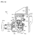
- Fig. 32 is an axially sectional view of a kingpin support casing 162 and kingpin sleeve 27 of rear transaxle 157 in vehicle 1 shown in Fig. 26, wherein a cam 162a is formed on kingpin support casing 162.
- Fig. 33(c) is an axially sectional view of clamping portion 71a of motor control arm 71 clamping cam 170a when steering wheel 16 is rotated so as to direct corresponding front wheel 36 on the turning outside of vehicle 1.
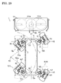
- each steering gear train 17 includes mutually meshing sector gears 22 and 30.
- Sector gear 22 has a toothed distal edge meshing with sector gear 30, and has a joint pin 24 at its proximal end.
- a link rod 25 is pivotally extended from joint pin 24 to each end of connection rod 20.
- a pivot shaft 23 of sector gear 22 is disposed between the toothed distal edge and proximal joint pin 24.
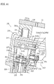
- a structure for steerably supporting transaxle 15 will be described with reference to Figs. 3 and 6.
- a joint member 34 is extended upward from the top of kingpin support casing 26 across sector gear 30.
- a cap 31 is fastened to joint member 34 by a bolt so as to cover the open top end of kingpin sleeve 27 above sector gear 30, thereby being fixed to kingpin support casing 26.
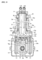
- Pistons 52 are axially and reciprocally inserted into cylinder block 51 around motor sleeve 56, thereby constituting hydraulic motor 10 as an axial piston type.
- hydraulic motor 10 may be made as a radial piston type. Heads of pistons 52 project outward from cylinder block 51 opposite to center section 41 so as to abut against a thrust bearing 54 of movable swash plate 53.
- An arcuately recessed guide seat 55 is fixedly fitted to transaxle housing 28 so as to slidably fit cradle type swash plate 53.
- a trunnion type movable swash plate may be used instead of guide seat 55.
- wet disk type brake assembly 39 is disposed between deceleration gear train 38 and center section 41.
- Brake assembly 39 includes a brake disk 66, a pressure plate 64 and a camshaft 63.
- Brake disk 66 is spline-fitted onto first sun gear 65 so as to be axially slidable along first sun gear 66.
- Vertical camshaft 63 is partly cut away to form a sectionally semicircular cam whose surface is fitted to pressure plate 64 adjacent to brake disk 66.
- An brake pad is disposed between ring gear 59 and brake disk 66.
- camshaft 63 projects upward from transaxle housing 28 and is fixedly provided thereon with a brake arm 68.
- Hydraulic motor 80 may be fixed in displacement, if possible.
- variable displacement hydraulic motor 80 has movable swash plate 53 actuated by an external actuator 101 through linkage 83.
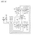
- controller 107 controls actuators 101 of right and left transaxles 13R and 13L based on the detection of rotary speeds of right and left axles 78 by rotary sensors 102 adjacent to respective axles 78.
- auxiliary speed changing valve 92 when auxiliary speed changing valve 92 is set at low speed level position L, fluid from hydraulic pump 5 through one of passages 91a and 91b is distributed between first and second hydraulic circuits 89 and 90 (between passages 89a and 90a or between passages 89b and 90b), and fluid to hydraulic pump 5 through the other passage 91b or 91a is collected from first and second hydraulic circuits 89 and 90 (from passages 89b and 90b or from passages 89a and 90a).
- all hydraulic motors 10 and 80 are fluidly connected in parallel to hydraulic pump 5, thereby reducing fluid supplied to each of motors 10 and 80.
- Vehicle 1 can travel in a four-wheel driving mode suitably for traction of a heavy machine and climbing a slope.
- auxiliary speed changing valve 92 when auxiliary speed changing valve 92 is set at middle speed level position M, fluid from hydraulic pump 5 through one of passages 91a and 91b is supplied to one of first and second hydraulic circuits 89 and 90, and then supplied to the other second or first hydraulic circuit 90 or 89 (from passage 90a to passage 89b through passages 90b and 89a, or from passage 89b to passage 90a through passages 90b and 89a), and returned to pump 5 through the other passage 91b or 91 a.
- the pair of hydraulic motors 10 and the pair of motors 80 are fluidly connected in tandem to hydraulic pump 5, thereby supplying all the amount of fluid from pump 5 to the pair of motors 10 and to the pair of motors 80.
- controller 107 Based on the detection of rotary speeds of axles 35 and 78 by sensors 102, if the detected rotary speed of one wheel 36 or 79 is deviate from its optimal rotary speed, and the wheel 36 or 79 is recognized to be slipping, controller 107 actuates either step motors 98a or 99a so as to restrict the amount of fluid flowing through motor 10 or 80 of slipping wheel 36 or 79, thereby forcibly supplying fluid to the other motor 10 or 80 of non-slipping wheel 36 or 79. Therefore, vehicle 1 can turn with constant driving of all wheels 36 and 79 (if auxiliary speed changing valve 92 is set at high speed level position H, with constant driving of both wheels 79).
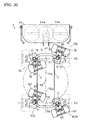
- Long kingpin sleeve 27 of transaxle 15 shown in Fig. 3 may be replaced with a solid shaft penetrated by axial holes for passing fluid and brake wire 49, similar to short kingpin block 142 shown in Fig. 22.
- a housing 124 incorporating hydraulic motor 10 is constituted by upper and lower housing halves 124a and 124b joined to each other through a horizontal joint surface on which the center axis of axle 35 is disposed.
- Axle 35 is journalled by upper and lower housing halves 124a and 124b through opposite bearings 67.
- Horizontal motor sleeve 56 is coaxially and relatively rotatably fitted on axle 35.
- Cylinder block 51 is spline-fitted on motor sleeve 56 and slidably rotatably fitted onto center section 41.
- Steering linkage 18 including right and left steering gear trains 17 is interposed between steering wheel 16 and respective front wheels 36, similar to Fig. 2. Similar to steering gear trains 17, right and left steering gear trains 155 are interposed between steering wheel 16 and respective rear wheels 167, as shown in Fig. 27. Front steering gear trains 17 and rear steering gear trains 155 are distributed symmetrically in the longitudinal direction of vehicle 1.
- first and second hydraulic circuits 89 and 172 are provided with flow control valves 98 and 99 with respective step motors 98a and 99a controlled by controller 107, according to the rotational angle of steering wheel 16 detected by steering angle sensor 104, the rotary speeds of wheels 36 and 167 detected by respective rotary sensors 102, the traveling direction of vehicle 1 corresponding to the depressed direction of speed control pedal 106, and the depressed or undepressed state of differential locking pedal 105. Therefore, the differential rotation of front wheels 36 and the differential rotation of rear wheels 167 can be suitably restricted.
- vehicle 1 shown in Fig. 37 to 50 comprises a vehicle chassis including left and right side frames 2, engine 3, hydraulic pump 5, mower 4 disposed between front wheels 236 and rear wheels 279.
- Rear-discharging chute 74 is extended rearward from mower 4 above engine 3 and hydraulic pump 5.
- Hydraulic pump 5 is disposed in front of engine 3 so as to be drivingly connected to engine 3.
- the layout of engine 3, mower 4 and hydraulic pump 5 may be changed suitably.
- a motor housing 327 incorporating hydraulic motor 210 has a lower kingpin portion 327a which is longer than kingpin portion 227a of motor housing 227.
- Motor shaft 256 of hydraulic motor 210 has a length L11 which is longer than that of motor shaft 256 shown in Fig. 39.
- a steerable axle housing 328 has a kingpin casing portion 328c, which is longer than kingpin casing portion 228c of axle housing 228 shown in Fig. 39.
- hydraulic motor 338 is slidably rotatably fitted onto a bottom surface of center section 241.
- a movable swash plate 339 is fitted onto a bottom surface of motor housing portion 344c.
- Axial motor shaft 346 is extended downward from hydraulic motor 338 through movable swash plate 339 into proximal housing half 344a below motor housing portion 344c.
- Bevel motor gear 258 is fixed onto a bottom end of motor shaft 258 so as to mesh with bevel gear 260 provided on clutch shaft 259.
Landscapes
- Engineering & Computer Science (AREA)
- Mechanical Engineering (AREA)
- Chemical & Material Sciences (AREA)
- Combustion & Propulsion (AREA)
- Transportation (AREA)
- General Engineering & Computer Science (AREA)
- Automation & Control Theory (AREA)
- Arrangement And Driving Of Transmission Devices (AREA)
- Arrangement Or Mounting Of Propulsion Units For Vehicles (AREA)
- Vehicle Body Suspensions (AREA)
- Steering-Linkage Mechanisms And Four-Wheel Steering (AREA)
- Motor Power Transmission Devices (AREA)
Priority Applications (1)
| Application Number | Priority Date | Filing Date | Title |
|---|---|---|---|
| EP08000143A EP1950071A1 (de) | 2003-12-11 | 2004-12-09 | Hydraulische Treibachse |
Applications Claiming Priority (4)
| Application Number | Priority Date | Filing Date | Title |
|---|---|---|---|
| JP2003413756A JP2005170254A (ja) | 2003-12-11 | 2003-12-11 | 操舵輪駆動ユニット及びそれを備えた四輪駆動車両 |
| JP2003413756 | 2003-12-11 | ||
| JP2004007631A JP2005199835A (ja) | 2004-01-15 | 2004-01-15 | 操舵輪駆動装置及びそれを備えた四輪駆動車両 |
| JP2004007631 | 2004-01-15 |
Related Child Applications (1)
| Application Number | Title | Priority Date | Filing Date |
|---|---|---|---|
| EP08000143A Division EP1950071A1 (de) | 2003-12-11 | 2004-12-09 | Hydraulische Treibachse |
Publications (3)
| Publication Number | Publication Date |
|---|---|
| EP1541402A2 true EP1541402A2 (de) | 2005-06-15 |
| EP1541402A3 EP1541402A3 (de) | 2005-12-21 |
| EP1541402B1 EP1541402B1 (de) | 2008-04-02 |
Family
ID=34525507
Family Applications (2)
| Application Number | Title | Priority Date | Filing Date |
|---|---|---|---|
| EP04029139A Expired - Lifetime EP1541402B1 (de) | 2003-12-11 | 2004-12-09 | Hydraulisches Achsgetriebe und Fahrzeug mit solchem Achsgetriebe |
| EP08000143A Withdrawn EP1950071A1 (de) | 2003-12-11 | 2004-12-09 | Hydraulische Treibachse |
Family Applications After (1)
| Application Number | Title | Priority Date | Filing Date |
|---|---|---|---|
| EP08000143A Withdrawn EP1950071A1 (de) | 2003-12-11 | 2004-12-09 | Hydraulische Treibachse |
Country Status (4)
| Country | Link |
|---|---|
| US (1) | US7591338B2 (de) |
| EP (2) | EP1541402B1 (de) |
| AT (1) | ATE391043T1 (de) |
| DE (1) | DE602004012825T2 (de) |
Cited By (2)
| Publication number | Priority date | Publication date | Assignee | Title |
|---|---|---|---|---|
| GB2414774A (en) * | 2004-06-03 | 2005-12-07 | Ford Global Tech Llc | A vehicle control system |
| WO2023275895A1 (en) * | 2021-07-01 | 2023-01-05 | Tirth Agro Technology Pvt. Ltd. | A hydraulic wheel drive assembly for agriculture machine |
Families Citing this family (14)
| Publication number | Priority date | Publication date | Assignee | Title |
|---|---|---|---|---|
| WO2004062956A1 (ja) * | 2003-01-08 | 2004-07-29 | Kanzaki Kokyukoki Mfg. Co., Ltd. | 油圧式車軸駆動装置 |
| DE102005034278A1 (de) * | 2005-07-22 | 2007-04-12 | Daimlerchrysler Ag | Antriebseinheit für ein Fahrzeug |
| JP5035866B2 (ja) * | 2005-10-04 | 2012-09-26 | ヤンマー株式会社 | 作業車両における動力伝達装置 |
| US7770685B2 (en) * | 2005-10-31 | 2010-08-10 | Deere & Company | Propulsion system for a work vehicle having a single drive pump and differential capability |
| JP2007283986A (ja) * | 2006-04-19 | 2007-11-01 | Kanzaki Kokyukoki Mfg Co Ltd | 油圧式車軸駆動装置 |
| US8000860B2 (en) * | 2007-04-04 | 2011-08-16 | Chung Shan Institute Of Science And Technology, Armaments Bureau, M.N.D. | Steering angle sensor |
| EP2190104A1 (de) * | 2007-09-11 | 2010-05-26 | Kabushiki Kaisha Yaskawa Denki | Hohles betätigungsglied |
| US8051940B2 (en) * | 2008-03-13 | 2011-11-08 | Dana Heavy Vehicle Systems Group, Llc | Hydraulic assist wheel end |
| RU2476344C1 (ru) * | 2011-06-28 | 2013-02-27 | Алексей Владимирович Смирнов | Способ поворота колесного транспортного средства |
| DE102013110134A1 (de) * | 2013-09-13 | 2015-04-02 | Blickle Räder + Rollen GmbH & Co. KG | Lenkvorrichtung sowie Fahrzeug mit einer solchen |
| US9969258B1 (en) * | 2014-04-22 | 2018-05-15 | Hydro-Gear Limited Partnership | Transaxle for zero-turn vehicle |
| JP2017163872A (ja) * | 2016-03-15 | 2017-09-21 | 本田技研工業株式会社 | 芝刈機 |
| JP2017163871A (ja) * | 2016-03-15 | 2017-09-21 | 本田技研工業株式会社 | 芝刈機 |
| US20190193558A1 (en) * | 2017-12-22 | 2019-06-27 | Caterpillar Inc. | System for providing torque assist in a vehicle |
Family Cites Families (34)
| Publication number | Priority date | Publication date | Assignee | Title |
|---|---|---|---|---|
| GB1088722A (en) * | 1964-03-07 | 1967-10-25 | Shaw & Sons Ltd Joshua | Improvements relating to steering means for lift trucks |
| US3351147A (en) * | 1965-12-29 | 1967-11-07 | Clark Equipment Co | Hydrostatic drive for vehicles |
| US3469646A (en) | 1967-03-29 | 1969-09-30 | Allis Chalmers Mfg Co | Hydraulic motor driven steerable wheel |
| BG25640A3 (bg) * | 1967-11-28 | 1978-11-10 | Deere & Co | Допълнителна хидростатично-механична предавка за моторни превозни средства, по-специално за трактори |
| US3997017A (en) * | 1974-01-14 | 1976-12-14 | Caterpillar Tractor Co. | Auxiliary hydrostatic front wheel drive system |
| DE3136433A1 (de) | 1981-09-14 | 1983-03-31 | Klaus Prof. Dr.-Ing. 4006 Erkrath Brankamp | Verfahren zum feststellen und erkennen von abweichungen zyklisch wiederkehrender vorgaenge zum umformen von werkstuecken von einem normalverlauf |
| JPS5858932U (ja) | 1981-10-16 | 1983-04-21 | ヤンマー農機株式会社 | 高架形農作業車の走行装置 |
| JPS59213520A (ja) * | 1983-05-16 | 1984-12-03 | Iseki & Co Ltd | 走行車両の前輪駆動装置 |
| JPS6237775A (ja) | 1985-08-10 | 1987-02-18 | Fujitsu Ltd | 自動取引装置による黒座自動開設方式 |
| JPS6237775U (de) | 1985-08-26 | 1987-03-06 | ||
| JP3367614B2 (ja) * | 1991-10-17 | 2003-01-14 | 株式会社小松製作所 | ダンプトラックの操舵輪油圧駆動装置 |
| FR2688175B3 (fr) * | 1992-03-04 | 1994-03-04 | Ecomat Ind | Vehicule auto-moteur entraine hydrauliquement. |
| FR2693154B1 (fr) * | 1992-11-09 | 1994-09-30 | Poclain Hydraulics Sa | Ensemble d'un organe de déplacement moteur et du dispositif de son montage à pivotement. |
| DE9305633U1 (de) * | 1993-04-15 | 1993-06-17 | EC Engineering + Consulting Spezialmaschinen GmbH, 7900 Ulm | Vorrichtung zum Antreiben, Führen und Lenken eines Fahrzeugrades |
| JPH07242130A (ja) * | 1994-03-07 | 1995-09-19 | Komatsu Ltd | 作業用車両の走行駆動装置 |
| CA2132684A1 (en) * | 1994-09-22 | 1996-03-23 | David L. Hoar | Utility vehicule |
| FR2726230A1 (fr) * | 1994-10-27 | 1996-05-03 | Peugeot | Dispositif et systeme de motopropulsion pour vehicule automobile |
| DE19602196A1 (de) * | 1996-01-23 | 1997-07-24 | Danfoss As | Hydraulisches Antriebssystem für Fahrzeuge |
| DE19648706C2 (de) * | 1996-11-25 | 1998-09-24 | Danfoss As | Hydraulische Schaltung für einen Fahrzeugantrieb mit zwei Hydromotoren |
| AU8662498A (en) * | 1997-07-25 | 1999-02-16 | Albert Madwed | Independently pivotable drivewheel for a wheeled chassis |
| US6206127B1 (en) * | 1998-02-27 | 2001-03-27 | Mi-Jack Products | Lead wheel steering system for a gantry crane |
| US6951259B2 (en) | 1998-12-03 | 2005-10-04 | Koji Irikura | Multi-wheel vehicle |
| JP4327284B2 (ja) * | 1998-04-15 | 2009-09-09 | 株式会社 神崎高級工機製作所 | 四輪駆動車両 |
| DE19826067B4 (de) * | 1998-06-12 | 2007-11-22 | Zf Friedrichshafen Ag | Getriebe für ein lenkbares Antriebsrad eines Flurförderfahrzeugs |
| US6098738A (en) * | 1998-07-08 | 2000-08-08 | White; Harvey | Hydraulic drive system for a vehicle |
| US6478099B1 (en) * | 2000-02-23 | 2002-11-12 | Albert Madwed | Wheelchair with offset drive wheels |
| US6302233B1 (en) * | 2000-06-06 | 2001-10-16 | Spicer Technologies, Inc. | Steering axle for vehicular hydraustatic drive system |
| ITRM20010274A1 (it) * | 2000-06-06 | 2002-11-25 | Dana Corp | Meccanismo compatto idraulico di comando, per complessi di ruota. |
| DE10030900A1 (de) * | 2000-06-23 | 2002-01-03 | Zahnradfabrik Friedrichshafen | Radantrieb |
| US6408972B1 (en) * | 2000-11-17 | 2002-06-25 | Sauer-Danfoss Inc. | Electronic traction control system |
| US6425453B1 (en) * | 2000-12-08 | 2002-07-30 | Clark Equipment Company | Transmission on all wheel steer power machine |
| US6732828B1 (en) * | 2002-10-22 | 2004-05-11 | Robert Abend | Hydraulically driven vehicle |
| JP4266643B2 (ja) | 2003-01-08 | 2009-05-20 | 株式会社 神崎高級工機製作所 | 走行駆動装置 |
| US7044259B2 (en) * | 2003-04-10 | 2006-05-16 | Kerwyn Stoll | Hydraulic transmission for driving and steering wheels |
-
2004
- 2004-12-09 AT AT04029139T patent/ATE391043T1/de not_active IP Right Cessation
- 2004-12-09 EP EP04029139A patent/EP1541402B1/de not_active Expired - Lifetime
- 2004-12-09 EP EP08000143A patent/EP1950071A1/de not_active Withdrawn
- 2004-12-09 DE DE602004012825T patent/DE602004012825T2/de not_active Expired - Fee Related
- 2004-12-10 US US11/008,662 patent/US7591338B2/en not_active Expired - Fee Related
Cited By (4)
| Publication number | Priority date | Publication date | Assignee | Title |
|---|---|---|---|---|
| GB2414774A (en) * | 2004-06-03 | 2005-12-07 | Ford Global Tech Llc | A vehicle control system |
| US7146261B2 (en) | 2004-06-03 | 2006-12-05 | Ford Global Technologies, Llc | Vehicle control system for exiting ruts |
| GB2414774B (en) * | 2004-06-03 | 2008-05-14 | Ford Global Tech Llc | A vehicle control system |
| WO2023275895A1 (en) * | 2021-07-01 | 2023-01-05 | Tirth Agro Technology Pvt. Ltd. | A hydraulic wheel drive assembly for agriculture machine |
Also Published As
| Publication number | Publication date |
|---|---|
| EP1541402A3 (de) | 2005-12-21 |
| EP1541402B1 (de) | 2008-04-02 |
| ATE391043T1 (de) | 2008-04-15 |
| DE602004012825D1 (de) | 2008-05-15 |
| DE602004012825T2 (de) | 2009-05-20 |
| EP1950071A1 (de) | 2008-07-30 |
| US20050126843A1 (en) | 2005-06-16 |
| US7591338B2 (en) | 2009-09-22 |
Similar Documents
| Publication | Publication Date | Title |
|---|---|---|
| EP1541402B1 (de) | Hydraulisches Achsgetriebe und Fahrzeug mit solchem Achsgetriebe | |
| US7987669B2 (en) | Hydraulic steering transaxle and hydraulic driving vehicle | |
| EP2295276B1 (de) | Hydraulische Achsenantriebsvorrichtung | |
| EP1847441B1 (de) | Hydrostatische Treibachse | |
| US8250862B1 (en) | Vehicle | |
| US6591936B2 (en) | Driving apparatus for speed changing and steering of a vehicle | |
| EP1413498A2 (de) | Vierradgetriebenes Fahrzeug | |
| US7314110B1 (en) | Hydraulic drive vehicle | |
| US20060278459A1 (en) | Hydraulically driven vehicle | |
| EP0927679B1 (de) | Lenkeinrichtung für ein fahrgetriebe | |
| US8205708B2 (en) | Hydraulic transaxle | |
| EP1533168B1 (de) | Hydraulische angetriebene Achse und entsprechendes Fahrzeug | |
| US20010040057A1 (en) | Multi-wheel vehicle with transmission for driving-steering | |
| JP2005155686A5 (de) | ||
| JP2008045723A (ja) | 油圧式無段変速装置 | |
| JP2005170254A (ja) | 操舵輪駆動ユニット及びそれを備えた四輪駆動車両 | |
| JP4520576B2 (ja) | クローラ走行車 | |
| JP2005199835A (ja) | 操舵輪駆動装置及びそれを備えた四輪駆動車両 | |
| JP4419349B2 (ja) | 走行装置 | |
| JP2005035402A (ja) | 油圧モータを備える車軸駆動装置 | |
| JPH06115456A (ja) | コンバイン等の走行伝動装置 | |
| JP2000211545A5 (de) |
Legal Events
| Date | Code | Title | Description |
|---|---|---|---|
| PUAI | Public reference made under article 153(3) epc to a published international application that has entered the european phase |
Free format text: ORIGINAL CODE: 0009012 |
|
| AK | Designated contracting states |
Kind code of ref document: A2 Designated state(s): AT BE BG CH CY CZ DE DK EE ES FI FR GB GR HU IE IS IT LI LT LU MC NL PL PT RO SE SI SK TR |
|
| AX | Request for extension of the european patent |
Extension state: AL BA HR LV MK YU |
|
| PUAL | Search report despatched |
Free format text: ORIGINAL CODE: 0009013 |
|
| AK | Designated contracting states |
Kind code of ref document: A3 Designated state(s): AT BE BG CH CY CZ DE DK EE ES FI FR GB GR HU IE IS IT LI LT LU MC NL PL PT RO SE SI SK TR |
|
| AX | Request for extension of the european patent |
Extension state: AL BA HR LV MK YU |
|
| 17P | Request for examination filed |
Effective date: 20060427 |
|
| 17Q | First examination report despatched |
Effective date: 20060719 |
|
| AKX | Designation fees paid |
Designated state(s): AT BE BG CH CY CZ DE DK EE ES FI FR GB GR HU IE IS IT LI LT LU MC NL PL PT RO SE SI SK TR |
|
| 17Q | First examination report despatched |
Effective date: 20060719 |
|
| GRAP | Despatch of communication of intention to grant a patent |
Free format text: ORIGINAL CODE: EPIDOSNIGR1 |
|
| GRAS | Grant fee paid |
Free format text: ORIGINAL CODE: EPIDOSNIGR3 |
|
| GRAA | (expected) grant |
Free format text: ORIGINAL CODE: 0009210 |
|
| AK | Designated contracting states |
Kind code of ref document: B1 Designated state(s): AT BE BG CH CY CZ DE DK EE ES FI FR GB GR HU IE IS IT LI LT LU MC NL PL PT RO SE SI SK TR |
|
| REG | Reference to a national code |
Ref country code: GB Ref legal event code: FG4D |
|
| RBV | Designated contracting states (corrected) |
Designated state(s): DE FR GB IT |
|
| REG | Reference to a national code |
Ref country code: CH Ref legal event code: PK Free format text: DIE BENENNUNG CH/LI WURDE VOR DER ERTEILUNG ZURUECKGENOMMEN. Ref country code: IE Ref legal event code: FG4D Ref country code: CH Ref legal event code: EP |
|
| REF | Corresponds to: |
Ref document number: 602004012825 Country of ref document: DE Date of ref document: 20080515 Kind code of ref document: P |
|
| ET | Fr: translation filed | ||
| PLBE | No opposition filed within time limit |
Free format text: ORIGINAL CODE: 0009261 |
|
| STAA | Information on the status of an ep patent application or granted ep patent |
Free format text: STATUS: NO OPPOSITION FILED WITHIN TIME LIMIT |
|
| 26N | No opposition filed |
Effective date: 20090106 |
|
| PGFP | Annual fee paid to national office [announced via postgrant information from national office to epo] |
Ref country code: IT Payment date: 20081220 Year of fee payment: 5 |
|
| PGFP | Annual fee paid to national office [announced via postgrant information from national office to epo] |
Ref country code: FR Payment date: 20081212 Year of fee payment: 5 |
|
| PGFP | Annual fee paid to national office [announced via postgrant information from national office to epo] |
Ref country code: DE Payment date: 20081231 Year of fee payment: 5 |
|
| PGFP | Annual fee paid to national office [announced via postgrant information from national office to epo] |
Ref country code: GB Payment date: 20081216 Year of fee payment: 5 |
|
| GBPC | Gb: european patent ceased through non-payment of renewal fee |
Effective date: 20091209 |
|
| REG | Reference to a national code |
Ref country code: FR Ref legal event code: ST Effective date: 20100831 |
|
| PG25 | Lapsed in a contracting state [announced via postgrant information from national office to epo] |
Ref country code: FR Free format text: LAPSE BECAUSE OF NON-PAYMENT OF DUE FEES Effective date: 20091231 |
|
| PG25 | Lapsed in a contracting state [announced via postgrant information from national office to epo] |
Ref country code: DE Free format text: LAPSE BECAUSE OF NON-PAYMENT OF DUE FEES Effective date: 20100701 |
|
| PG25 | Lapsed in a contracting state [announced via postgrant information from national office to epo] |
Ref country code: GB Free format text: LAPSE BECAUSE OF NON-PAYMENT OF DUE FEES Effective date: 20091209 |
|
| PG25 | Lapsed in a contracting state [announced via postgrant information from national office to epo] |
Ref country code: IT Free format text: LAPSE BECAUSE OF NON-PAYMENT OF DUE FEES Effective date: 20091209 |