EP1541299B1 - Motorservolenksystem - Google Patents
Motorservolenksystem Download PDFInfo
- Publication number
- EP1541299B1 EP1541299B1 EP03723150A EP03723150A EP1541299B1 EP 1541299 B1 EP1541299 B1 EP 1541299B1 EP 03723150 A EP03723150 A EP 03723150A EP 03723150 A EP03723150 A EP 03723150A EP 1541299 B1 EP1541299 B1 EP 1541299B1
- Authority
- EP
- European Patent Office
- Prior art keywords
- steering
- speed reduction
- shaft
- rotation angle
- detecting
- Prior art date
- Legal status (The legal status is an assumption and is not a legal conclusion. Google has not performed a legal analysis and makes no representation as to the accuracy of the status listed.)
- Expired - Lifetime
Links
- 230000002093 peripheral effect Effects 0.000 claims description 7
- 230000005540 biological transmission Effects 0.000 claims description 3
- 238000003780 insertion Methods 0.000 claims description 2
- 230000037431 insertion Effects 0.000 claims description 2
- 238000004804 winding Methods 0.000 description 5
- 230000003287 optical effect Effects 0.000 description 3
- 239000011347 resin Substances 0.000 description 3
- 229920005989 resin Polymers 0.000 description 3
- 230000000694 effects Effects 0.000 description 2
- 208000027418 Wounds and injury Diseases 0.000 description 1
- 230000006835 compression Effects 0.000 description 1
- 238000007906 compression Methods 0.000 description 1
- 230000006378 damage Effects 0.000 description 1
- 230000002542 deteriorative effect Effects 0.000 description 1
- 238000006073 displacement reaction Methods 0.000 description 1
- 208000014674 injury Diseases 0.000 description 1
- 238000000034 method Methods 0.000 description 1
- 239000007787 solid Substances 0.000 description 1
Images


Classifications
-
- G—PHYSICS
- G01—MEASURING; TESTING
- G01L—MEASURING FORCE, STRESS, TORQUE, WORK, MECHANICAL POWER, MECHANICAL EFFICIENCY, OR FLUID PRESSURE
- G01L5/00—Apparatus for, or methods of, measuring force, work, mechanical power, or torque, specially adapted for specific purposes
- G01L5/22—Apparatus for, or methods of, measuring force, work, mechanical power, or torque, specially adapted for specific purposes for measuring the force applied to control members, e.g. control members of vehicles, triggers
- G01L5/221—Apparatus for, or methods of, measuring force, work, mechanical power, or torque, specially adapted for specific purposes for measuring the force applied to control members, e.g. control members of vehicles, triggers to steering wheels, e.g. for power assisted steering
-
- B—PERFORMING OPERATIONS; TRANSPORTING
- B62—LAND VEHICLES FOR TRAVELLING OTHERWISE THAN ON RAILS
- B62D—MOTOR VEHICLES; TRAILERS
- B62D15/00—Steering not otherwise provided for
- B62D15/02—Steering position indicators ; Steering position determination; Steering aids
- B62D15/021—Determination of steering angle
- B62D15/0215—Determination of steering angle by measuring on the steering column
-
- B—PERFORMING OPERATIONS; TRANSPORTING
- B62—LAND VEHICLES FOR TRAVELLING OTHERWISE THAN ON RAILS
- B62D—MOTOR VEHICLES; TRAILERS
- B62D5/00—Power-assisted or power-driven steering
- B62D5/04—Power-assisted or power-driven steering electrical, e.g. using an electric servo-motor connected to, or forming part of, the steering gear
- B62D5/0409—Electric motor acting on the steering column
-
- Y—GENERAL TAGGING OF NEW TECHNOLOGICAL DEVELOPMENTS; GENERAL TAGGING OF CROSS-SECTIONAL TECHNOLOGIES SPANNING OVER SEVERAL SECTIONS OF THE IPC; TECHNICAL SUBJECTS COVERED BY FORMER USPC CROSS-REFERENCE ART COLLECTIONS [XRACs] AND DIGESTS
- Y10—TECHNICAL SUBJECTS COVERED BY FORMER USPC
- Y10T—TECHNICAL SUBJECTS COVERED BY FORMER US CLASSIFICATION
- Y10T74/00—Machine element or mechanism
- Y10T74/19—Gearing
- Y10T74/1987—Rotary bodies
- Y10T74/19888—External and internal teeth
Definitions
- the present invention relates to a motor-driven power steering apparatus structured such as to apply a steering assist force generated by a motor to a steering system of a motor vehicle or a vehicle, and more particularly to a rotation angle sensor for detecting a rotation angle (a steering angle) of a steering shaft.
- a motor-driven power steering apparatus is generally mounted on the vehicle.
- the motor-driven power steering apparatus is structured such as to assist a load of the steering shaft and energize via a transmission mechanism such as a gear of a speed reduction gear or the like on the basis of a driving force of the motor.
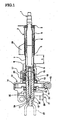
- a steering shaft 1 having a steering wheel in a leading end (a right end in Fig. 1 ) is rotatably supported by a ball bearing 3 within a coaxial steering column 2, and is extended in an axial direction.
- the steering shaft 1 is constituted by a tubular outer shaft 4, and an inner shaft 5 fitted within the outer shaft 4.
- the steering column 2 is formed by connecting a tubular outer column 6 and an inner column 7 press fitted and fixed within the outer column 6. Further, when an impact load is applied in a compression direction at a time of colliding, the outer shaft 4 and the outer column 6 are pressed into a base end side (a left side in Fig. 1 ), absorbs an energy by contracting an entire length and absorbs an impact applied to a body of the driver colliding with the steering wheel.
- an input shaft 9 and an approximately tubular output shaft 10 are connected to the base end side (the left side in Fig. 1 ) of the inner shaft 5 via a torsion bar 8.
- the torsion bar 8 is inserted into the output shaft 10, one end of the torsion bar 8 is press fitted and fixed to the input shaft 9, and the other end thereof is fixed to the output shaft 10 by a pin 11.
- a speed reduction gear unit 12 is supported to an outer periphery of a center portion of the output shaft 10 by a pair of ball bearings 13 and 13.
- the speed reduction gear unit 12 is constituted by a worm wheel 14 fixedly mounted to an outer periphery of the output shaft 10 in accordance with a press fitting, a worm 15 engaging with the worm wheel 14, and a motor in which the worm 15 is mounted to an output shaft 16, and is structured such as to reduce a speed of rotation of the motor via the worm 15 and the worm wheel 14 so as to transmit a torque, on the basis of driving the motor.
- a torque sensor 17 is arranged in a leading end side (a right side in Fig. 1 ) of the speed reduction gear unit 12, and the torque sensor 17 is provided with the torsion bar 8 and an electromagnetic yoke 20 receiving a coil winding 19 in an outer periphery of a spline groove 18 formed in a leading end of the output shaft 10, and is structured such as to detect a magnetic change by the coil winding 19 within the electromagnetic yoke 20, by generating a torsion angle in correspondence to a torque generated in the steering shaft 1.
- a rotation angle sensor (a steering sensor) 21 is arranged in a base end side (a left side in Fig. 1 ) of the speed reduction gear unit 12, and the rotation angle sensor 21 is constituted by a tubular hollow member 22 arranged in an outer periphery of the output shaft 10, and a casing 23 rotatably supporting the hollow member 22.
- a projection 24 is extended to an inner side from an inner peripheral surface, and is engaged with a locking hole 25 provided in an outer peripheral surface of the output shaft 10, whereby the hollow member 22 is integrally rotated with the output shaft 10.
- the structure is made such as to detect the rotation angle of the output shaft 10 by detecting a relative displacement between the casing 23 and the hollow member 22 by a detecting means 26 provided in the casing 23. Accordingly, the steering state of the steering wheel is detected from the rotation angle (the steering angle).
- reference numeral 27 denotes a universal joint for connecting to an intermediate shaft
- reference numeral 28 denotes a bracket for mounting the steering apparatus to the vehicle body.
- the steering shaft 1 and the steering column 2 are respectively constituted by two members (the outer shaft 4 and the inner shaft 5, and the outer column 6 and the inner column 7), and the outer shaft 4 and the outer column 6 can be moved at a certain range (a stroke t) in the axial direction at a time of collision. Therefore, the steering column 2 or the like is plastically deformed at a time of moving, and it is possible to absorb the energy generated at a time when the passenger collides with the steering wheel, on the basis of the deformation energy.
- the absorbing amount of the energy is determined by a product of a force applied by the impact and the stroke t, it is important to make the stroke t as long as possible in order to make the impact force to the passenger small so as to reduce an injury.
- the speed reduction gear and the torque sensor 17 are provided in the axial direction of the steering shaft 1, and it is necessary that the rotation angle sensor 21 is provided so as to have such a space that the steering shaft, that is, the output shaft 10 is exposed between the universal joint 27 and the speed reduction unit 12. Accordingly, the stroke t is limited to a fixed length from the space of the vehicle body, and there is a problem that it is hard to secure the stroke t of the energy absorbing mechanism to a sufficient length in the limited space.
- a rotation detecting device having features similar to those as set out in the preamble of present claim 1. Particularly, a steering output part is fixed with a worm wheel for power assist. By a spur gear formed on the worm wheel, an input gear of a detecting unit is rotated with a speed increase. Within the detecting unit, provided is a speed-reducing mechanism for speed-reducing the rotation of the detecting shaft.
- an object of the present invention is to provide a motor-driven power steering apparatus in which a rotation angle sensor can be attached to a steering shaft in the limited space without deteriorating an energy absorbing function for protecting the passenger.
- a motor-driven power steering apparatus which is particularly structured such as to assist a steering force of a steering shaft via a transmission mechanism such as a gear of a speed reduction gear or the like by a rotation force of an electric motor on the basis of a steering torque detected by a torque sensor, comprising:
- the object mentioned above can be effectively achieved by the structure in which the detected portion is arranged in a worm wheel within the speed reduction gear, and the rotation of the worm wheel is detected by the detecting portion.
- the object mentioned above can be effectively achieved by the structure in which the detecting portion is mounted to a recess groove formed in any one side within the worm wheel within the speed reduction gear.
- the object mentioned above can be effectively achieved by the structure in which the detecting portion is arranged at a position opposing to a side surface of the detected portion, thereby detecting a magnetic or optical angle signal from the detected portion.
- the object mentioned above can be effectively achieved by the structure in which the detected portion is structured by a recess groove formed in any one side within the worm wheel within the speed reduction gear, and is constituted by a small gear provided in an inner peripheral surface of the recess groove.
- the rotation angle sensor is constituted by an annular detected portion provided in the side surface of the worm wheel within the speed reduction gear, and a detecting portion provided at a position opposing to the detected portion.
- the object mentioned above can be effectively achieved by the structure in which the speed reduction gear is supported by a plurality of bearings.
- Fig. 2 shows a first embodiment of the present invention, and is a view showing an outline structure of a steering system.
- a steering shaft 31 rotating on the basis of an operation of a steering wheel is connecting by press fitting and fixing a solid cylindrical shaft-like inner shaft 33 to a tubular outer shaft 32. Further, the steering shaft 31 is rotatably supported at an end portion of a steering column 35 by a bearing 34 such as a deep groove type ball bearing or the like.
- the steering column 35 is connected by press fitting and fixing an inner column 37 to a tubular outer column 36.
- the steering shaft 31 and the steering column 35 are structured such that when a great load is applied in an axial direction, the outer shaft 32 moves along the inner shaft 33 and the outer column 36 moves along the inner column 37 respectively in the axial direction within a range of the stroke t in the axial direction so as to be plastically deformed.
- the steering shaft 31 and the steering column 35 are both structured by combining two members 32 and 33, and 36 and 37, and forms an energy absorbing mechanism structured such as to absorb an impact applied to a body of a driver colliding with the steering wheel.
- the energy of the steering shaft 31 and the steering column 35 is absorbed by a plastic deformation at a time of relative movement between two members, however, it is possible to absorb the energy by the plastic deformation between the steering column 35 and a bracket 75 for fixing the steering column 35 to the vehicle body.
- an input shaft 40 and an approximately cylindrical output shaft 41 are connected to a base end side (a left side in Fig. 1 ) of the steering shaft 31 via a torsion bar 39.
- the torsion bar 39 is inserted into the output shaft 41, one end thereof is press fitted and fixed to the input shaft 40, and the other end thereof is fixed to the output shaft 41 by a pin 41a.
- a speed reduction gear unit 42 is supported in an outer periphery of the output shaft 41 by a pair of ball bearings 43 and 43, and a torque sensor 44 is arranged in a leading end side (a right side in Fig. 1 ) of the speed reduction gear unit 42.
- the torque sensor 44 is provided with the torsion bar 39, and an electromagnetic yoke 47 arranged in an outer periphery of a spline groove 45 formed in a leading end of the output shaft 41 and receiving a coil winding 46, and is structured such as to detect a magnetic change by the coil winding 46 within the electromagnetic yoke 47 by generating a torsion in the torsion bar 39 in correspondence to the torque generated in the steering shaft 31.
- the speed reduction gear is constituted by a worm wheel 48 fixedly mounted to an outer periphery of the output shaft 41 in accordance with a press fitting, a worm 49 engaged with the worm wheel 48, and a motor mounting the worm 49 to the output shaft 50, and is structured such as to reduce a speed of the rotation of the motor via the worm 49 and the worm wheel 48 by driving the motor so as to transmit the torque.
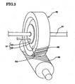
- the rotation angle sensor 51 is constituted by a thin disc-like detected portion 52 provided within the speed reduction gear unit 42 and having a smaller diameter than the worm wheel 48, and the steering shaft 31, that is, a detecting portion 53 provided in an outer side of the bearing 43 in a radial direction of the output shaft 41, as shown in Fig. 3 .
- the detecting portion 53 is arranged at a position opposing to a side surface of the detected portion 52, and is integrally mounted to the output shaft 41 within a recess groove 54 formed in any one side within the worm wheel 48.
- the detecting portion 53 is structured such as to detect the rotation angle of the output shaft 41 by detecting an angle signal from the detected portion 52 in a magnetic manner or an optical manner, oran electric resistance manner or an electrical capacitance manner.
- the detected portion 52 of the rotation angle sensor 51 is provided within the speed reduction gear unit 42, and the detecting portion 53 is provided in the outer side of the ball bearing 43 in the radial direction of the output shaft 41. Accordingly, it is not necessary that the exclusive space for mounting the rotation angle sensor is provided on the steering shaft 31. As a result, it is possible to make the stroke t of the energy absorbing mechanism, that is, a distance in the axial direction by which the outer column 36 of the steering column 35 moves along the inner column 37 long.
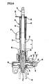
- Fig. 4 shows a second embodiment in accordance with the present invention. A description of the second embodiment will be omitted by attaching the same reference numerals as those of the first embodiment to the same members.
- the worm wheel 48 is constituted by an approximately ring-like core rod boss portion 61, a gear base portion 62 integrally formed in an outer peripheral side of the core rod boss portion 61 by a resin, and a resin gear 63 formed in an outer peripheral side of the gear base portion 62 and engaged with the worm 49. Further, a recess groove is formed in a left side in Fig.
- a rotation angle sensor 65 of the output shaft 41 is constituted by the detected portion 64 and a detecting portion 67 for detecting the rotation of the output shaft 41.
- the detecting portion 67 is provided with a protruding shaft 71 extending from a main body 68 arranged in an outer side of the speed reduction gear unit 42 into the speed reduction gear unit 42 via an insertion hole 70 of a housing cover 69, and a detecting gear 72 mounted to a leading end of the protruding shaft 71.
- the rotation angle sensor 65 is structured, as shown in Fig.
- the detected portion 64 of the rotation angle sensor 65 is provided within the speed reduction gear unit 42, and the detecting portion 67 is provided in the outer side of the bearing 43 of the speed reduction gear unit 42 in the radial direction of the output shaft 41. Therefore, even in the case that the rotation angle sensor 65 is provided in the steering shaft 31, it is possible to sufficiently secure the stroke t of the energy absorbing mechanism, and the energy absorbing capacity is not sacrificed. Accordingly, the same operations and effects as those of the first embodiment mentioned above can be achieved even by the second embodiment.
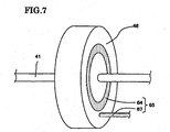
- Fig. 6 shows a third embodiment in accordance with the present invention. A description of the third embodiment will be omitted by attaching the same reference numerals as those of the first embodiment to the same members.
- the rotation angle sensor 65 is constituted by an annular detected portion 64 provided in a side surface of a leading end side (a right side in Fig. 6 ) of the worm wheel 48, and a detecting portion 67 provided at a position opposing to the detected portion 64, as shown in Fig. 7 .
- the detected portion 64 of the rotation angle sensor 65 is provided within the speed reduction gear unit 42, and the detecting portion 67 is provided in the outer side of the bearing 43 of the speed reduction gear unit 42 in the radial direction of the output shaft 41. Therefore, even in the case that the rotation angle sensor 65 is provided in the steering shaft 31, it is possible to sufficiently secure the stroke t of the energy absorbing mechanism, and the energy absorbing capacity is not sacrificed. Accordingly, the same operations and effects as those of the first and second embodiments mentioned above can be achieved even by the third embodiment.
- reference numeral 74 denotes a universal joint for connecting to an intermediate shaft
- reference numeral 75 denotes a bracket for mounting the steering apparatus to the vehicle body.
- the rotation angle sensor for detecting the steering state of the steering wheel in the case that the rotation angle sensor for detecting the steering state of the steering wheel is provided, the detected portion is provided in the worm wheel or the like within the speed reduction gear, and the detecting portion is provided in the outer side of the bearing of the speed reduction gear in the radial direction of the steering shaft. Therefore, the rotation angle of the steering shaft is detected by utilizing the worm wheel of the speed reduction gear and detecting the angle signal from the detected portion provided in the worm wheel by the detecting portion while using the magnetic or optical method, or the like.
- the exclusive space for arranging the rotation angle sensor is provided in the axial direction of the steering shaft, and it is possible to effectively utilize the stroke of the energy absorbing mechanism. Accordingly, even in the case that the rotation angle sensor is provided in the limited space in the axial direction of the steering shaft, such as the column type motor-driven power steering apparatus or the like, it is possible to keep a safety with respect to the impact load generated at a time of the collision of the vehicle or the like, without sacrificing the energy absorbing capacity.
Landscapes
- Engineering & Computer Science (AREA)
- Chemical & Material Sciences (AREA)
- Combustion & Propulsion (AREA)
- Transportation (AREA)
- Mechanical Engineering (AREA)
- Physics & Mathematics (AREA)
- General Physics & Mathematics (AREA)
- Power Steering Mechanism (AREA)
- Retarders (AREA)
- Auxiliary Drives, Propulsion Controls, And Safety Devices (AREA)
- Steering-Linkage Mechanisms And Four-Wheel Steering (AREA)
- Steering Control In Accordance With Driving Conditions (AREA)
Claims (3)
- Motorbetriebene Servolenkvorrichtung aufweisend:einen Momentsensor (44), der ein Lenkmoment erkennt, das durch ein Lenkrad eingegeben wird;einen elektrischen Motor, der basierend auf dem Lenkmoment, das von dem Momentsensor (44) erkannt wird, antreibt;einen Übertragungsmechanismus (48, 49) einer Geschwindigkeitsreduktionseinheit (42), die eine Rotationskraft des elektrischen Motors auf eine Lenkradsäule (31) überträgt;einen Rotationswinkelsensor (65), um einen Lenkzustand des Lenkrades zu erkennen;einen detektierten Abschnitt (64) des Rotationswinkelsensors (65), der innerhalb der Geschwindigkeitsreduktionseinheit (42) ausgebildet ist;und einen Detektionsabschnitt (67) des Rotationswinkelsensors (65), der in einer radialen Richtung der Lenksäule (31) und ausserhalb eines Lagers (43) in der Geschwindigkeitsreduktionseinheit (42) vorgesehen ist,dadurch gekennzeichnet,
dass der detektierte Abschnitt (64) durch eine vertiefte Rille gebildet wird, die auf einer Seite innerhalb eines Schneckenrades (48) in der Geschwindigkeitsreduktionseinheit (42) ausgebildet ist, und von einem kleinen Zahnrad gebildet wird, das in einer inneren Umfangsfläche der vertieften Rille vorgesehen ist, und
dass der Detektionsabschnitt (67) aufweist: einen Hauptkörper (68), der in einem Aussenbereich der Geschwindigkeitsreduktionseinheit (42) angeordnet ist; eine hervorstehende Welle (71), die sich von dem Hauptkörper (68) über eine Einfügeöffnung (70) einer Gehäuseabdeckung (69) der Gechwindigkeitsreduktionseinheit (42) in die Geschwindigkeitsreduktionseinheit (42) erstreckt, und ein Detektionszahnrad (72), das an einem vorderen Ende der vorstehenden Welle (71) befestigt ist. - Motorbetriebene Servolenkvorrichtung nach Anspruch 1, wobei die Geschwindikeitsreduktionseinheit (42) von einer Mehrzahl von Lagern (43) abgestützt wird.
- Motorbetriebene Servolenkvorrichtung nach Anspruch 1, die zusätzlich einen Energieabsorptionsmechanismus (32-33, 36-37) aufweist, der so aufgebaut ist, dass die Lenkwelle (31) und eine Lenksäule (35), welche die Lenkwelle (31) rotierbar abstützt, sich in einem vorgegebenen Bereich (t) axial bewegen, und wobei der Energieabsorptionsmechanismus (32-33; 36-37) und der Momentsensor (44) zwischen dem Lenkrad und der Geschwindigkeitsreduktionseinheit (42) angeordnet sind.
Applications Claiming Priority (3)
| Application Number | Priority Date | Filing Date | Title |
|---|---|---|---|
| JP2002195042 | 2002-07-03 | ||
| JP2002195042 | 2002-07-03 | ||
| PCT/JP2003/005001 WO2004004992A1 (ja) | 2002-07-03 | 2003-04-18 | 電動パワーステアリング装置 |
Publications (3)
| Publication Number | Publication Date |
|---|---|
| EP1541299A1 EP1541299A1 (de) | 2005-06-15 |
| EP1541299A4 EP1541299A4 (de) | 2006-07-12 |
| EP1541299B1 true EP1541299B1 (de) | 2008-05-14 |
Family
ID=30112325
Family Applications (1)
| Application Number | Title | Priority Date | Filing Date |
|---|---|---|---|
| EP03723150A Expired - Lifetime EP1541299B1 (de) | 2002-07-03 | 2003-04-18 | Motorservolenksystem |
Country Status (9)
| Country | Link |
|---|---|
| US (2) | US20050230178A1 (de) |
| EP (1) | EP1541299B1 (de) |
| JP (1) | JP4412172B2 (de) |
| KR (1) | KR100575572B1 (de) |
| CN (1) | CN1332842C (de) |
| AT (1) | ATE395236T1 (de) |
| AU (1) | AU2003235265A1 (de) |
| DE (1) | DE60321014D1 (de) |
| WO (1) | WO2004004992A1 (de) |
Families Citing this family (16)
| Publication number | Priority date | Publication date | Assignee | Title |
|---|---|---|---|---|
| EP1495942B1 (de) * | 2002-04-15 | 2011-12-21 | Nsk Ltd. | Elektrische servolenkvorrichtung |
| JP4877715B2 (ja) * | 2005-09-28 | 2012-02-15 | 株式会社ジェイテクト | トルク検出装置及びこれを用いた電動パワーステアリング装置 |
| EP2305537B1 (de) * | 2008-07-15 | 2014-04-23 | JTEKT Corporation | Lenkvorrichtung für ein fahrzeug |
| DE102009021081B4 (de) * | 2008-07-18 | 2017-07-06 | Asm Automation Sensorik Messtechnik Gmbh | Magnetischer Winkelsensor |
| CN101865275B (zh) * | 2010-05-28 | 2012-10-24 | 上海应用技术学院 | 与减速器组合在一起的扭矩传感器 |
| JP2012040980A (ja) * | 2010-08-20 | 2012-03-01 | Showa Corp | 電動パワーステアリング装置 |
| JP2012131420A (ja) * | 2010-12-22 | 2012-07-12 | Jtekt Corp | 車両用操舵装置 |
| JP5618885B2 (ja) * | 2011-03-28 | 2014-11-05 | 株式会社ケーヒン | 車両のアクセル開度検出装置 |
| WO2013061391A1 (ja) * | 2011-10-24 | 2013-05-02 | 三菱電機株式会社 | 電動パワーステアリング装置 |
| JP2014015130A (ja) * | 2012-07-09 | 2014-01-30 | Jtekt Corp | ステアリング装置 |
| CN103770831B (zh) * | 2012-10-17 | 2016-12-07 | 上海航天汽车机电股份有限公司 | 电动助力转向装置及其安装方法 |
| JP6396201B2 (ja) * | 2014-12-22 | 2018-09-26 | 株式会社ジェイテクト | 電動パワーステアリング装置 |
| DE102015000928B3 (de) | 2015-01-28 | 2016-07-21 | Thyssenkrupp Ag | Vorrichtung zur Einbringung eines Hilfsdrehmoments in eine Lenkwelle einer elektromechanischen Hilfskraftlenkung |
| CN106809212A (zh) * | 2017-03-30 | 2017-06-09 | 福建船政交通职业学院 | 一种爆胎车身稳定控制系统 |
| DE102018107890B4 (de) * | 2018-04-04 | 2021-04-29 | Schaeffler Technologies AG & Co. KG | Lenkkopflageranordnung |
| DE102018117155A1 (de) * | 2018-07-16 | 2020-01-16 | Trw Automotive Gmbh | Lenkungsunterstützungsvorrichtung |
Family Cites Families (21)
| Publication number | Priority date | Publication date | Assignee | Title |
|---|---|---|---|---|
| US4364011A (en) * | 1979-05-16 | 1982-12-14 | Ransome Hoffmann Pollard Ltd. | Mechanical assemblies employing sensing means for sensing motion or position |
| US4363011A (en) * | 1980-03-17 | 1982-12-07 | Henryk Turczanski | Contact electrodes for reed switches |
| JPS63155009U (de) * | 1987-03-30 | 1988-10-12 | ||
| JPH083162Y2 (ja) * | 1988-07-08 | 1996-01-29 | 松下電器産業株式会社 | センサ付ウォームギヤモータ |
| GB2261860B (en) * | 1991-10-30 | 1995-08-09 | Honda Motor Co Ltd | Steering apparatus with variable steering angle ratio for pitman arm steering mechanism |
| JPH05229445A (ja) * | 1992-02-05 | 1993-09-07 | Toyota Motor Corp | 電気式パワーステアリング装置のハンドル復元制御装置 |
| US5979587A (en) * | 1997-06-06 | 1999-11-09 | Ford Global Technologies, Inc. | Electrically assisted power steering apparatus |
| US6400278B1 (en) * | 1997-08-25 | 2002-06-04 | Robert Bosch Gmbh | Motor vehicle closing device with a position recognition system for a moveable control element |
| DE19747638C1 (de) * | 1997-10-29 | 1999-07-01 | Zahnradfabrik Friedrichshafen | Elektrisch unterstützte Hilfskraftlenkung für Kraftfahrzeuge |
| JPH11287637A (ja) | 1998-03-31 | 1999-10-19 | Nikon Corp | 透過偏芯測定装置及び方法 |
| JPH11287634A (ja) * | 1998-04-01 | 1999-10-19 | Tokai Rika Co Ltd | 車両用ステアリングセンサ |
| DE19825888A1 (de) * | 1998-06-10 | 1999-12-16 | Mannesmann Vdo Ag | Antriebseinheit mit Positionserfassung |
| DE19840895A1 (de) * | 1998-09-08 | 2000-03-16 | Bosch Gmbh Robert | Scheibenwischer-Antriebsvorrichtung |
| GB9902438D0 (en) * | 1999-02-05 | 1999-03-24 | Trw Lucas Varity Electric | Improvements relating to electric power assisted steering assemblies |
| JP3412579B2 (ja) * | 1999-10-19 | 2003-06-03 | トヨタ自動車株式会社 | 車両の電動パワーステアリング装置 |
| JP3551243B2 (ja) * | 2000-04-05 | 2004-08-04 | トヨタ自動車株式会社 | 伝達比可変機構のロック方法及びロック装置、ブラシレスモータの駆動制御方法 |
| JP2002107112A (ja) * | 2000-09-27 | 2002-04-10 | Koyo Seiko Co Ltd | 回転角度検出装置、トルク検出装置及び舵取装置 |
| JP2003065753A (ja) * | 2001-08-28 | 2003-03-05 | Showa Corp | パワーステアリングのステアリング回転角度検出装置 |
| EP1495942B1 (de) * | 2002-04-15 | 2011-12-21 | Nsk Ltd. | Elektrische servolenkvorrichtung |
| JP2003329436A (ja) | 2002-05-16 | 2003-11-19 | Alps Electric Co Ltd | 回転検出装置 |
| JP4451631B2 (ja) | 2003-10-10 | 2010-04-14 | 日本精工株式会社 | 電動パワーステアリング装置 |
-
2003
- 2003-04-18 DE DE60321014T patent/DE60321014D1/de not_active Expired - Lifetime
- 2003-04-18 WO PCT/JP2003/005001 patent/WO2004004992A1/ja active IP Right Grant
- 2003-04-18 CN CNB038156717A patent/CN1332842C/zh not_active Expired - Fee Related
- 2003-04-18 US US10/519,485 patent/US20050230178A1/en not_active Abandoned
- 2003-04-18 JP JP2004519198A patent/JP4412172B2/ja not_active Expired - Fee Related
- 2003-04-18 AT AT03723150T patent/ATE395236T1/de not_active IP Right Cessation
- 2003-04-18 EP EP03723150A patent/EP1541299B1/de not_active Expired - Lifetime
- 2003-04-18 AU AU2003235265A patent/AU2003235265A1/en not_active Abandoned
- 2003-04-18 KR KR1020047021643A patent/KR100575572B1/ko not_active IP Right Cessation
-
2006
- 2006-05-30 US US11/442,336 patent/US7204167B2/en not_active Expired - Fee Related
Also Published As
| Publication number | Publication date |
|---|---|
| ATE395236T1 (de) | 2008-05-15 |
| CN1332842C (zh) | 2007-08-22 |
| WO2004004992A1 (ja) | 2004-01-15 |
| US20060213717A1 (en) | 2006-09-28 |
| CN1665651A (zh) | 2005-09-07 |
| KR100575572B1 (ko) | 2006-05-02 |
| JPWO2004004992A1 (ja) | 2005-11-04 |
| US7204167B2 (en) | 2007-04-17 |
| KR20050023356A (ko) | 2005-03-09 |
| AU2003235265A1 (en) | 2004-01-23 |
| JP4412172B2 (ja) | 2010-02-10 |
| EP1541299A4 (de) | 2006-07-12 |
| EP1541299A1 (de) | 2005-06-15 |
| US20050230178A1 (en) | 2005-10-20 |
| DE60321014D1 (de) | 2008-06-26 |
Similar Documents
| Publication | Publication Date | Title |
|---|---|---|
| US7204167B2 (en) | Motor-driven power steering apparatus | |
| US7237646B2 (en) | Electrically driven power steering apparatus | |
| JP4716679B2 (ja) | ウォーム減速機及び電動式パワーステアリング装置 | |
| US6619421B2 (en) | Electric power steering device | |
| JP4784828B2 (ja) | 車両用操舵装置 | |
| US9932065B2 (en) | Steering device | |
| EP1985521B1 (de) | Energieaufnehmendes Lenksystem | |
| JP2011069495A (ja) | ウォーム減速機及び電動式パワーステアリング装置 | |
| US6364049B1 (en) | Electric powering steering apparatus | |
| US20090050400A1 (en) | Electric power steering apparatus | |
| EP1571063B1 (de) | Lenkvorrichtung | |
| GB2290761A (en) | Electric power steering system with impact absorbing means | |
| US20220379949A1 (en) | Steer by wire type steering apparatus | |
| EP1862371B1 (de) | Elektrische Servolenkung | |
| JP6759779B2 (ja) | 電動パワーステアリング装置 | |
| JP2008001137A (ja) | ステアリング装置 | |
| JP3883761B2 (ja) | 衝撃吸収式パワーステアリング装置 | |
| JP5212714B2 (ja) | 車両用衝撃吸収操舵装置 | |
| EP0629540A1 (de) | Stossdämpfervorrichtung für eine Lenksäule und Verfahren zu ihrer Herstellung | |
| CN218750980U (zh) | 线控转向下执行器机构、线控转向系统及车辆 | |
| JP3604488B2 (ja) | 衝撃吸収式ステアリング装置 | |
| JP3634124B2 (ja) | ステアリング装置 | |
| JP2001191934A (ja) | 電動パワーステアリング装置 | |
| JPH04331663A (ja) | 動力舵取装置 |
Legal Events
| Date | Code | Title | Description |
|---|---|---|---|
| PUAI | Public reference made under article 153(3) epc to a published international application that has entered the european phase |
Free format text: ORIGINAL CODE: 0009012 |
|
| 17P | Request for examination filed |
Effective date: 20050201 |
|
| AK | Designated contracting states |
Kind code of ref document: A1 Designated state(s): AT BE BG CH CY CZ DE DK EE ES FI FR GB GR HU IE IT LI LU MC NL PT RO SE SI SK TR |
|
| AX | Request for extension of the european patent |
Extension state: AL LT LV MK |
|
| DAX | Request for extension of the european patent (deleted) | ||
| A4 | Supplementary search report drawn up and despatched |
Effective date: 20060614 |
|
| RIC1 | Information provided on ipc code assigned before grant |
Ipc: G01B 7/30 20060101ALI20060608BHEP Ipc: B62D 5/04 20060101ALI20060608BHEP Ipc: B62D 15/02 20060101AFI20060608BHEP |
|
| 17Q | First examination report despatched |
Effective date: 20070104 |
|
| GRAP | Despatch of communication of intention to grant a patent |
Free format text: ORIGINAL CODE: EPIDOSNIGR1 |
|
| GRAS | Grant fee paid |
Free format text: ORIGINAL CODE: EPIDOSNIGR3 |
|
| GRAA | (expected) grant |
Free format text: ORIGINAL CODE: 0009210 |
|
| STAA | Information on the status of an ep patent application or granted ep patent |
Free format text: STATUS: THE PATENT HAS BEEN GRANTED |
|
| AK | Designated contracting states |
Kind code of ref document: B1 Designated state(s): AT BE BG CH CY CZ DE DK EE ES FI FR GB GR HU IE IT LI LU MC NL PT RO SE SI SK TR |
|
| REG | Reference to a national code |
Ref country code: GB Ref legal event code: FG4D |
|
| REG | Reference to a national code |
Ref country code: CH Ref legal event code: EP |
|
| REG | Reference to a national code |
Ref country code: IE Ref legal event code: FG4D Free format text: LANGUAGE OF EP DOCUMENT: FRENCH |
|
| REF | Corresponds to: |
Ref document number: 60321014 Country of ref document: DE Date of ref document: 20080626 Kind code of ref document: P |
|
| PG25 | Lapsed in a contracting state [announced via postgrant information from national office to epo] |
Ref country code: SI Free format text: LAPSE BECAUSE OF FAILURE TO SUBMIT A TRANSLATION OF THE DESCRIPTION OR TO PAY THE FEE WITHIN THE PRESCRIBED TIME-LIMIT Effective date: 20080514 |
|
| PG25 | Lapsed in a contracting state [announced via postgrant information from national office to epo] |
Ref country code: ES Free format text: LAPSE BECAUSE OF FAILURE TO SUBMIT A TRANSLATION OF THE DESCRIPTION OR TO PAY THE FEE WITHIN THE PRESCRIBED TIME-LIMIT Effective date: 20080825 Ref country code: FI Free format text: LAPSE BECAUSE OF FAILURE TO SUBMIT A TRANSLATION OF THE DESCRIPTION OR TO PAY THE FEE WITHIN THE PRESCRIBED TIME-LIMIT Effective date: 20080514 |
|
| NLV1 | Nl: lapsed or annulled due to failure to fulfill the requirements of art. 29p and 29m of the patents act | ||
| PG25 | Lapsed in a contracting state [announced via postgrant information from national office to epo] |
Ref country code: NL Free format text: LAPSE BECAUSE OF FAILURE TO SUBMIT A TRANSLATION OF THE DESCRIPTION OR TO PAY THE FEE WITHIN THE PRESCRIBED TIME-LIMIT Effective date: 20080514 Ref country code: AT Free format text: LAPSE BECAUSE OF FAILURE TO SUBMIT A TRANSLATION OF THE DESCRIPTION OR TO PAY THE FEE WITHIN THE PRESCRIBED TIME-LIMIT Effective date: 20080514 |
|
| PG25 | Lapsed in a contracting state [announced via postgrant information from national office to epo] |
Ref country code: SE Free format text: LAPSE BECAUSE OF FAILURE TO SUBMIT A TRANSLATION OF THE DESCRIPTION OR TO PAY THE FEE WITHIN THE PRESCRIBED TIME-LIMIT Effective date: 20080814 Ref country code: PT Free format text: LAPSE BECAUSE OF FAILURE TO SUBMIT A TRANSLATION OF THE DESCRIPTION OR TO PAY THE FEE WITHIN THE PRESCRIBED TIME-LIMIT Effective date: 20081014 Ref country code: DK Free format text: LAPSE BECAUSE OF FAILURE TO SUBMIT A TRANSLATION OF THE DESCRIPTION OR TO PAY THE FEE WITHIN THE PRESCRIBED TIME-LIMIT Effective date: 20080514 Ref country code: CZ Free format text: LAPSE BECAUSE OF FAILURE TO SUBMIT A TRANSLATION OF THE DESCRIPTION OR TO PAY THE FEE WITHIN THE PRESCRIBED TIME-LIMIT Effective date: 20080514 |
|
| PG25 | Lapsed in a contracting state [announced via postgrant information from national office to epo] |
Ref country code: BE Free format text: LAPSE BECAUSE OF FAILURE TO SUBMIT A TRANSLATION OF THE DESCRIPTION OR TO PAY THE FEE WITHIN THE PRESCRIBED TIME-LIMIT Effective date: 20080514 Ref country code: SK Free format text: LAPSE BECAUSE OF FAILURE TO SUBMIT A TRANSLATION OF THE DESCRIPTION OR TO PAY THE FEE WITHIN THE PRESCRIBED TIME-LIMIT Effective date: 20080514 Ref country code: RO Free format text: LAPSE BECAUSE OF FAILURE TO SUBMIT A TRANSLATION OF THE DESCRIPTION OR TO PAY THE FEE WITHIN THE PRESCRIBED TIME-LIMIT Effective date: 20080514 |
|
| PLBE | No opposition filed within time limit |
Free format text: ORIGINAL CODE: 0009261 |
|
| STAA | Information on the status of an ep patent application or granted ep patent |
Free format text: STATUS: NO OPPOSITION FILED WITHIN TIME LIMIT |
|
| 26N | No opposition filed |
Effective date: 20090217 |
|
| PG25 | Lapsed in a contracting state [announced via postgrant information from national office to epo] |
Ref country code: EE Free format text: LAPSE BECAUSE OF FAILURE TO SUBMIT A TRANSLATION OF THE DESCRIPTION OR TO PAY THE FEE WITHIN THE PRESCRIBED TIME-LIMIT Effective date: 20080514 Ref country code: BG Free format text: LAPSE BECAUSE OF FAILURE TO SUBMIT A TRANSLATION OF THE DESCRIPTION OR TO PAY THE FEE WITHIN THE PRESCRIBED TIME-LIMIT Effective date: 20080814 |
|
| PG25 | Lapsed in a contracting state [announced via postgrant information from national office to epo] |
Ref country code: IT Free format text: LAPSE BECAUSE OF FAILURE TO SUBMIT A TRANSLATION OF THE DESCRIPTION OR TO PAY THE FEE WITHIN THE PRESCRIBED TIME-LIMIT Effective date: 20080514 |
|
| REG | Reference to a national code |
Ref country code: CH Ref legal event code: PL |
|
| GBPC | Gb: european patent ceased through non-payment of renewal fee |
Effective date: 20090418 |
|
| PG25 | Lapsed in a contracting state [announced via postgrant information from national office to epo] |
Ref country code: LI Free format text: LAPSE BECAUSE OF NON-PAYMENT OF DUE FEES Effective date: 20090430 Ref country code: CH Free format text: LAPSE BECAUSE OF NON-PAYMENT OF DUE FEES Effective date: 20090430 |
|
| REG | Reference to a national code |
Ref country code: IE Ref legal event code: MM4A |
|
| PG25 | Lapsed in a contracting state [announced via postgrant information from national office to epo] |
Ref country code: IE Free format text: LAPSE BECAUSE OF NON-PAYMENT OF DUE FEES Effective date: 20090418 Ref country code: GB Free format text: LAPSE BECAUSE OF NON-PAYMENT OF DUE FEES Effective date: 20090418 Ref country code: MC Free format text: LAPSE BECAUSE OF NON-PAYMENT OF DUE FEES Effective date: 20090430 |
|
| PG25 | Lapsed in a contracting state [announced via postgrant information from national office to epo] |
Ref country code: GR Free format text: LAPSE BECAUSE OF FAILURE TO SUBMIT A TRANSLATION OF THE DESCRIPTION OR TO PAY THE FEE WITHIN THE PRESCRIBED TIME-LIMIT Effective date: 20080815 |
|
| PG25 | Lapsed in a contracting state [announced via postgrant information from national office to epo] |
Ref country code: LU Free format text: LAPSE BECAUSE OF NON-PAYMENT OF DUE FEES Effective date: 20090418 |
|
| PG25 | Lapsed in a contracting state [announced via postgrant information from national office to epo] |
Ref country code: HU Free format text: LAPSE BECAUSE OF FAILURE TO SUBMIT A TRANSLATION OF THE DESCRIPTION OR TO PAY THE FEE WITHIN THE PRESCRIBED TIME-LIMIT Effective date: 20081115 |
|
| PG25 | Lapsed in a contracting state [announced via postgrant information from national office to epo] |
Ref country code: TR Free format text: LAPSE BECAUSE OF FAILURE TO SUBMIT A TRANSLATION OF THE DESCRIPTION OR TO PAY THE FEE WITHIN THE PRESCRIBED TIME-LIMIT Effective date: 20080514 |
|
| PG25 | Lapsed in a contracting state [announced via postgrant information from national office to epo] |
Ref country code: CY Free format text: LAPSE BECAUSE OF FAILURE TO SUBMIT A TRANSLATION OF THE DESCRIPTION OR TO PAY THE FEE WITHIN THE PRESCRIBED TIME-LIMIT Effective date: 20080514 |
|
| REG | Reference to a national code |
Ref country code: FR Ref legal event code: PLFP Year of fee payment: 14 |
|
| PGFP | Annual fee paid to national office [announced via postgrant information from national office to epo] |
Ref country code: FR Payment date: 20160309 Year of fee payment: 14 |
|
| PGFP | Annual fee paid to national office [announced via postgrant information from national office to epo] |
Ref country code: DE Payment date: 20160412 Year of fee payment: 14 |
|
| REG | Reference to a national code |
Ref country code: DE Ref legal event code: R082 Ref document number: 60321014 Country of ref document: DE Representative=s name: SCHMITT-NILSON SCHRAUD WAIBEL WOHLFROM PATENTA, DE |
|
| REG | Reference to a national code |
Ref country code: DE Ref legal event code: R119 Ref document number: 60321014 Country of ref document: DE |
|
| REG | Reference to a national code |
Ref country code: FR Ref legal event code: ST Effective date: 20171229 |
|
| PG25 | Lapsed in a contracting state [announced via postgrant information from national office to epo] |
Ref country code: FR Free format text: LAPSE BECAUSE OF NON-PAYMENT OF DUE FEES Effective date: 20170502 Ref country code: DE Free format text: LAPSE BECAUSE OF NON-PAYMENT OF DUE FEES Effective date: 20171103 |