EP1540604B1 - Point de recuperation d'objets consignes ou empruntes - Google Patents
Point de recuperation d'objets consignes ou empruntes Download PDFInfo
- Publication number
- EP1540604B1 EP1540604B1 EP03794744A EP03794744A EP1540604B1 EP 1540604 B1 EP1540604 B1 EP 1540604B1 EP 03794744 A EP03794744 A EP 03794744A EP 03794744 A EP03794744 A EP 03794744A EP 1540604 B1 EP1540604 B1 EP 1540604B1
- Authority
- EP
- European Patent Office
- Prior art keywords
- sorting
- objects
- arrangement
- return
- arrangement according
- Prior art date
- Legal status (The legal status is an assumption and is not a legal conclusion. Google has not performed a legal analysis and makes no representation as to the accuracy of the status listed.)
- Expired - Lifetime
Links
- 230000000903 blocking effect Effects 0.000 claims abstract description 18
- 238000000034 method Methods 0.000 claims description 19
- 230000032258 transport Effects 0.000 claims description 14
- 230000033001 locomotion Effects 0.000 claims description 13
- 230000008569 process Effects 0.000 claims description 8
- 230000009471 action Effects 0.000 claims description 4
- 238000012544 monitoring process Methods 0.000 claims description 4
- 230000001960 triggered effect Effects 0.000 claims description 4
- 230000008859 change Effects 0.000 claims description 3
- 238000012545 processing Methods 0.000 claims description 3
- 230000004044 response Effects 0.000 claims description 3
- 230000004888 barrier function Effects 0.000 claims 2
- 230000003287 optical effect Effects 0.000 claims 1
- 238000012795 verification Methods 0.000 claims 1
- 238000001514 detection method Methods 0.000 description 5
- 230000005684 electric field Effects 0.000 description 4
- 201000009032 substance abuse Diseases 0.000 description 4
- 239000002699 waste material Substances 0.000 description 4
- 238000013475 authorization Methods 0.000 description 3
- 230000008901 benefit Effects 0.000 description 3
- 230000001419 dependent effect Effects 0.000 description 3
- 239000000463 material Substances 0.000 description 3
- 230000007246 mechanism Effects 0.000 description 3
- 241000384008 Sisis Species 0.000 description 2
- 239000003795 chemical substances by application Substances 0.000 description 2
- 239000000047 product Substances 0.000 description 2
- 235000013361 beverage Nutrition 0.000 description 1
- 238000000151 deposition Methods 0.000 description 1
- 230000007613 environmental effect Effects 0.000 description 1
- 230000002349 favourable effect Effects 0.000 description 1
- 239000000835 fiber Substances 0.000 description 1
- 230000001771 impaired effect Effects 0.000 description 1
- 239000007788 liquid Substances 0.000 description 1
- 238000013507 mapping Methods 0.000 description 1
- 238000007363 ring formation reaction Methods 0.000 description 1
- 102220292970 rs546292445 Human genes 0.000 description 1
- 230000011664 signaling Effects 0.000 description 1
- 239000013589 supplement Substances 0.000 description 1
- 230000007723 transport mechanism Effects 0.000 description 1
- 239000002023 wood Substances 0.000 description 1
Images


Classifications
-
- G—PHYSICS
- G07—CHECKING-DEVICES
- G07F—COIN-FREED OR LIKE APPARATUS
- G07F7/00—Mechanisms actuated by objects other than coins to free or to actuate vending, hiring, coin or paper currency dispensing or refunding apparatus
- G07F7/06—Mechanisms actuated by objects other than coins to free or to actuate vending, hiring, coin or paper currency dispensing or refunding apparatus by returnable containers, i.e. reverse vending systems in which a user is rewarded for returning a container that serves as a token of value, e.g. bottles
- G07F7/0609—Mechanisms actuated by objects other than coins to free or to actuate vending, hiring, coin or paper currency dispensing or refunding apparatus by returnable containers, i.e. reverse vending systems in which a user is rewarded for returning a container that serves as a token of value, e.g. bottles by fluid containers, e.g. bottles, cups, gas containers
-
- G—PHYSICS
- G07—CHECKING-DEVICES
- G07F—COIN-FREED OR LIKE APPARATUS
- G07F1/00—Coin inlet arrangements; Coins specially adapted to operate coin-freed mechanisms
- G07F1/04—Coin chutes
- G07F1/041—Coin chutes with means, other than for testing currency, for dealing with inserted foreign matter, e.g. "stuffing", "stringing" or "salting"
- G07F1/042—Coin chutes with means, other than for testing currency, for dealing with inserted foreign matter, e.g. "stuffing", "stringing" or "salting" the foreign matter being a long flexible member attached to a coin
- G07F1/043—Cutting or trapping of the flexible member or the attached coin
-
- G—PHYSICS
- G07—CHECKING-DEVICES
- G07F—COIN-FREED OR LIKE APPARATUS
- G07F7/00—Mechanisms actuated by objects other than coins to free or to actuate vending, hiring, coin or paper currency dispensing or refunding apparatus
- G07F7/06—Mechanisms actuated by objects other than coins to free or to actuate vending, hiring, coin or paper currency dispensing or refunding apparatus by returnable containers, i.e. reverse vending systems in which a user is rewarded for returning a container that serves as a token of value, e.g. bottles
- G07F7/069—Mechanisms actuated by objects other than coins to free or to actuate vending, hiring, coin or paper currency dispensing or refunding apparatus by returnable containers, i.e. reverse vending systems in which a user is rewarded for returning a container that serves as a token of value, e.g. bottles by box-like containers, e.g. videocassettes, books
Definitions
- the present invention relates to an arrangement for the repossession of pledged or assignable objects and / or objects associated with a lending system according to the preamble of claim 1, a use of the arrangement and a method for the return of occupied by a pledge or assignable objects and / or objects belonging to a lending system.
- the arrangement described in WO99 / 64974 for the return of books in libraries is easy to manipulate, i. for example, by tying a string to the object and retracting the object after it has been registered, the user person can easily steal their object even though the object is registered as being returned.
- a reception station for the reception of reusable waste.
- the waste units placed in an identification chamber, if pledged, entered by means of a rocker in a waste container, or if not pledged, ejected again.
- an accepting station for liquid containers, such as beverage cans comprising a tubular input in which the can is detected when falling down on pledge authorization.
- a return device in which a lock is arranged, in which an imported object is identified, after the lock of the affiliation of the object were detected.
- the object of the present invention is therefore to propose an arrangement or a device which takes into account the above-described problem, and by means of which abuses in the return or withdrawal of Objects of deposit systems or lending systems can be largely prevented.
- Another object of the present invention is to allow for a quick and efficient sorting of the returned objects.
- Yet another object is to enable a quick detection of the return authorization or a quick clearance of a person returning an object.
- the arrangement for the return of objects pledged or assignable to a deposit and / or objects belonging to a lending system which are provided with at least one identifiable identification code, be identified by a receiving station or a receiving area for the input or the reception area Positioning of the withdrawing object by a consumer or a user.
- at least one reading device which is provided to determine the affiliation of the object to a specific deposit or lending system.
- a means of transport which is operatively connected to the above-mentioned reading device such that upon positive determination of the affiliation of the object, the transport is activated to transport the object away.
- a shut-off device is provided, through which the object is transported through a positive determination of affiliation.
- the means of transport will not be activated at all or the object will be transported to a location intended for non-associated objects, whereby neither a deposit payment nor a return of the object will be effected or registered.
- means are provided on the obturator in order to make a backward movement of the object after passing at least more difficult.
- monitoring means are also possible to provide monitoring means on the obturator in order to detect a backward movement of the object.
- Both measures are suitable for preventing the aforementioned abuses, for example to prevent withdrawal by means of a cord or other suitable means by the consumer returning the object or by the user of the lending system.
- the monitoring means may be, for example, at least one position sensor which indicates whether an object is located in the region of the obturator or in which direction the object is being moved.
- a further identification sensor is provided for the identification of the withdrawn object in order to capture the corresponding deposit amount in the case of a pledged object or, in the case of a lending system, to register the return of the object and the object itself.
- RFID Radio frequency identification data
- both the reading device, the identification sensor (s) and the writing device operate in the radio frequency range to read and / or transmit data.
- Vorguggar further proposed to connect the reverse vending machine or the receiving station electrically and / or logically with a subsequent sorting system.
- This sorting system receives the information for each withdrawn object, for example from the receiving station, in order to then assign this to a corresponding sorting path. That is, the corresponding sorting path is preferably activated automatically if the respective Object has reached the appropriate point in the sorting system or on the sorting path.
- the detection of the objects and their position to enable a correct sorting can be done using a variety of sensor types. For example, if information about an object is stored on its RFID tag, whether the object is a book, a CD, a video, etc., it is e.g. it is possible to arrange an RFID reader in each sorting path in order to detect or recognize the object or its position. According to a further embodiment variant, it is also possible to determine position and object by means of light sensors and / or position encoders, for example on the drive motor of a conveyor belt.
- the objects are sorted out by means of swivel arm, guide, lever arm, etc. at the respectively assigned location of the sorting system or on the correct sorting path.
- a tilt filter unit which is cascaded, i. the sorters are placed one after the other.
- the tilting sorters are electrically and logically connected to one another and can be controlled electrically and / or logically by the return robots, such as, for example, the receiving station.
- the Objects for return authorization must be detected quickly, or that a quick return of a person returning an object is made possible. This can be particularly difficult if a reverse vending machine or an inventive arrangement for each input object fetch and interpret information from an external database, which in case of bad response times in the computer network, in case of system failure, or temporary connection difficulties to unacceptable waiting for customers can lead.
- a database be provided at the arrangement or recording station, which may, for example, periodically download information from the external database concerning all objects in the system.
- a database be provided at the arrangement or recording station, which may, for example, periodically download information from the external database concerning all objects in the system.
- inventively defined arrangement is particularly suitable for deposit systems, such as consumer goods, such as in a pledge bottles, containers, trays, Harrassen, etc. or for lending systems, such as libraries for borrowing books, CD's, computer games , Videos, magazines and the like
- Both the reading and possibly also the writing are preferably carried out in the radio frequency range, wherein the objects to be identified are preferably provided with a so-called RFID label or tag.
- the arrangement is designed in such a way that only redeemed objects are accepted and that objects of customers resp. by users can not be withdrawn by manipulation after the object has already been registered, and for example, a receipt is printed.
- the arrangement should be able to be used both for objects of deposit systems and lending systems, which are provided with read-only RFID tags, as well as for those objects which are provided with an RFID tag, with at least one rewritable field, which, for example, the status objects such as "eligible", "no longer eligible”; "stored in the library” or “borrowed”, etc.
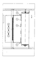
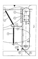
- FIG. 1 It is therefore an arrangement or a return module according FIG. 1 proposed.
- the object 9 is guided in the input port 1.
- the object is detected by interrogator 2. If the object 9 is identified as entitled to return, the conveyor belt 3 starts, and the door 4 opens, so that the object can be conveyed past the door 4.
- Interrogator 5 now changes, if present, the content of an information field on the RFID tag to record that the object has been accepted. This is done to prevent abuse. Instead, if the RFID tag does not have such an information cell, it is preferably suggested that for each returned object, the identification number of the object be stored in a list and that number be blocked for withdrawal during a reasonable time. This blocking can only affect the corresponding return device or, advantageously, a group of redemption devices that jointly manage a revocation list via data exchange.
- the door 4 immediately, unless a new returnable object is detected by the interrogator 2. If no new object is detected, an acknowledgment is printed. If a new object is identified as it is typed, the above process repeats until all returnable objects are entered by the user. Only then will the receipt be printed out.
- the door 4 always closes after an object has passed the door 4, regardless of whether a new object that can be returned is detected by the interrogator 2.
- the door will open again after a certain delay time.
- the variant with position sensor (s) 6 is preferred in the input 1 (in front of the door 4), so that the door 4 is only opened when the interrogator 2 detects a returnable object and the position sensor (s) 6 additionally indicates (-in) that an object is in the opening 1, respectively. is entered.
- the sequence control it is important to know whether the object is in front of, under or behind the door 4. At the same time it is important to secure the door so that it does not close if a person introduces their hand should.
- a position sensor 15 can according to FIG. 4 monitor the door 4.
- the position sensor 15 consisting for example of a photoemitter 11, a detector 12 and the light beam 13 near the bottom of the conveyor belt 3, either immediately before, arranged immediately after the door 4 or directly in the door.
- the closing movement of the door 4 can begin immediately when the light beam 13 is no longer interrupted; which normally means that the input object 9 is over at the door 4. If the light beam 13 is interrupted, there is some object under the door 4 and the door 4 may not close until the interruption of the light beam is canceled. If the light beam 13 is interrupted for longer than a certain time, you can turn off the belt 3 or drive backwards to ensure that people can not be injured by the closing movement of the door 4.
- the door 4 can be closed again, if despite an object by interrogator 2 and sensor 6 within a certain time no object reaches the sensor 15. It is also possible to measure how long an object interrupts the light beam 13 and thus, on the basis of the belt speed, draw conclusions about the object length and possible manipulation attempts. Comment: The placement of the position sensor after the door is less favorable, since in this case theoretically a Object can be directly under the door, without that this is detected by the position sensor.
- FIG. 5 an embodiment of the door 4 is preferred FIG. 5 which is difficult to open with external force.
- a lock 20 is provided which, as soon as the door is closed, is locked with, for example, a magnetic switch.
- the door may also be a swing gate / flap with e.g. a lock which opens when a redeemable object is entered and closes and locks again when the object passes the door.
- a swing gate / flap with e.g. a lock which opens when a redeemable object is entered and closes and locks again when the object passes the door.
- the electric fields 20 and 21 of the antennas are in FIG. 6 described. In this area, therefore, the materials influencing the electric fields should be avoided.
- plastic rollers are to be used for the drive and deflection roller, that the Support plate for the band made of wood or plastic, and that no components that significantly affect the electric field, are placed in the described magnetic field.
- Case A Before the receipt issue (i.e., before the door 4 is closed), the input object is sent by e.g. withdrawn a string, this is registered by the interrogator 2 and possibly also by position sensor 6 and 15. The redemption transaction already made is reversed in this case by the data processing unit and the operator does not get a receipt. In this case, the manipulation attempt is documented and recorded in an automaton log and an appropriate manipulation message is given to the operator and / or operator.
- Case B If, when entering the nth object, the operator attempts to retract the n-1 previously entered objects by means of a string, the return movement is also detected by the interrogators 2 and 5, possibly also by the position sensors 6 and 15. The return transaction becomes reversed in this case and the operator does not get a receipt. In this case, the manipulation attempt is documented and recorded in an automaton log and an appropriate manipulation message is given to the operator and / or operator.
- Case C Should the manipulator first enter n-1 objects retractable with a string and for which a receipt has been printed, and then, by means of a returnable object, ensure that the conveyor belt starts up and the door 4 opens , the operator may be able to retract the previously entered n-1 objects. However, the retraction is detected by interrogator 2 and 5 and optionally by position sensors 6 and 15. In this case, a theft alarm is triggered and the door 4 closed as soon as possible when it is free. (Checked by position sensor 15).
- the door 4 is open only as long as necessary.
- the door 4 is closed immediately when the light path 13 is interrupted, and according to the first embodiment, if no additional further returnable objects are in the input.
- the door 4 is also closed without regard to the presence of other returnable objects, if a theft attempt is detected by the system.
- An alarm to the operator is generated immediately if the light path 13 is interrupted for more than a time Y.
- the time Y can be calculated using the maximum length of an object and the transport speed of the conveyor belt.
- the door 4 closes (if possible) immediately if a backward movement of any interregator or position sensor is detected.
- a position sensor 7 is mounted at the output 8, which first detects the backward movement.
- the position sensor 7 need not be mounted on the machine itself, but can also be mounted in connection with the entry into a collection container, a sorting system or conveyor system.
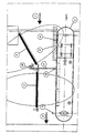
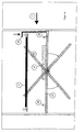
- FIG. 7 and 8th proposed that a mechanical arrangement is used which makes the retraction of objects which have left the conveyor belt 3 impossible or at least severely hampered.
- the withdrawal from a collection container 41 can be as an alternative also prevent so that mechanical guides are placed in the opening, which Grasping handles act. When pulling back, it is unlikely that the objects can go back through the opening.
- a knife 32 be mounted on a chute 31, so that a string is cut on retraction.
- the knife should be sprung so that it yields under the weight of an object 9 and, when unloaded, springs to the original position corresponding to the optimum cutting angle. Knives may be mounted where it is to be understood that in an attempt to retract an object, a leading edge of the string is created.
- An added benefit of the knife 32, according to FIG. 9 is that the original position of the knife prevents it from being pulled back, because when it is pulled back, the object on the knife will stand up when it is pulled back.
- the band 3 be turned off and possibly reversed if the sensor 15 is interrupted for longer than a certain time, and the door is prevented from being closed by an object.
- the door 4 opens and an object can be transported past the door 4. Should now turn out that by operator manipulation a non-returnable object is transported, this is determined when the object has passed completely through the door 4 and the interrogator 5 does not see the object read at the interrogator 2. In this case, the tape only runs forward until any other objects in the system have left the tape. This is detected by position sensors and / or by the interrogator 5. Then the tape 3 is reversed and said object is transported back to the input 1. The door 4 closes as soon as the object is transported past. The tape stops when the object on the tape is positioned so that it is easy for the customer to remove / undo. This is controlled by the position sensor 6. On the screen or other convenient display, the customer is asked to remove the item from the input.
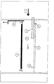
- a door 74 in a similar embodiment of the door 4 also mounted at the exit.
- the distance between the doors is at least as long as the length of the largest returnable object.
- the idea now is that always at least one of the doors is 4 or 74 too. In this way, a lock is realized, which prevents any kind of manipulation.
- the process is as follows: The door 4 opens when a returnable object 9 is identified at input 1 and closes when the object is conveyed past the door 4.
- the interrogator 5 registers the transaction and opens the door 74 so that the object is issued. Immediately when the object has been successfully issued, the door 74 closes. As soon as successfully closed, the door 4 becomes the Possibility to reopen.
- the belt 3 is reversed and the door 4 is opened again to return the object to the customer.
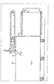
- FIG. 12 is proposed according to a further embodiment of the arrangement that already at the input port 1, a re-closable door 34 is arranged, through which the object 9 is entered into an input area.
- the object 9 now lies on a pivotable slide 27, which is fastened to the hinge 28, for example.
- FIG. 13 shows the same arrangement as FIG. 12 and schematically the further processing and transport process for the object 9 is shown.
- the user now closes the door 34, so that the input port 1 is closed.
- the door 34 is locked.
- the interrogator 2 now reads the object 9 and, if it is eligible for return, or is detected belonging to the lending system, the following actions are triggered.
- the chute 27 is pivoted downwards by means of, for example, a motor, so that the object 9 falls down into a collecting container or onto a transport / sorting system.
- the slide 27 is free again, it is immediately swung open and returned to its original state. This can be determined for example by a limit switch 29.
- the repositioning triggers that the lock of the door 34 is released and the door can be opened again.
- the door can be fully, semi-automatically or manually operated. In any case, a signaling is attached to the user when a new object can be inserted and when the door can be opened or closed.
- the swiveling chute according to Figures 12 and 13 can of course be realized in different variants.
- the hinge can be mounted on four possible sides, or the chute is divided into two hinged flaps with two opposing hinges. Upper but, as in FIG. 14 shown, you can swing the swivel slide, for example, about a centrally located axis, back and forth, so that you have the opportunity to swing the chute in two directions. In this way, one can sort identified objects by identity in one direction or the other.
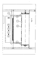
- FIG. 15 shows an inventive arrangement similar to that shown in FIG. 11 in that first the object is input via the input opening 1 by opening a first flap 44, which can pivot about an axis 43, into a lock-like chamber 46. Subsequently, the flap 44 is firmly locked and the inserted into the chamber 46 object 9 detected by the interrogator 2. If the object 9 is detected as being eligible for a mortgage or belonging to the loan system, a second door 47, which in turn can be pivoted about the axis 43, for example, is opened so that the object 9 from the lock-like chamber 46 in FIG Arrow direction can be transported away. The further interrogator 5 can now be used to identify or further process the RFID tag on the object 9. Of course, it is also possible to arrange interrogator 5 and possibly a writing device in the region of the chamber 46.
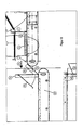
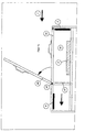
- Fig. 16 is schematically shown in longitudinal section of such a sorting system, which is suitable for separating the withdrawn objects or to supply separate containers.
- an object 1 is input to the receiving station 100 via an input 1, where it is detected or detected by the interrogator 2 and possibly 5.
- information about a designated sorting can be detected by the interrogator 2 and / or 5, which information is stored on an RFID label, for example.
- sorting information or specifications are retrieved from an external server with a database, such as a library server.
- a database such as a library server.
- both information from an RFID label, as well as an external server are needed to define the sorting path.
- the object can, for example, pass the defined door 4, as with reference to the preceding figures, in order to control a so-called sorting system with one or more sorting paths.
- Using a mapping table is a cost effective and efficient method because the sorting information needs to be collected, checked, and processed only once per object.
- the sorting system has a plurality of sorting units 51, 53, 55, each with 2 or more sorting paths on. Since the sorting system is electrically and / or logically connected to the input station or the interrogator 2 and / or 5, the corresponding sorting path can be automatically activated when the respective object has reached the corresponding sorting unit or the corresponding sorting path.
- the detection of the position of the object for the purpose of correct sorting can be done by means of various sensor types respectively.
- this may be unnecessarily expensive and the position may not be accurately detected because the RFID tag may be located anywhere on the object.
- a light sensor may be arranged in each sorting unit, such as a fiber optic device type FVDK 10P83Y0 with a simplex light guide from Baumer Electric AG or a photocell, such as the type FPDK 14P5101 / S35A from Baumer Electric AG, arranged around the Detect position of the respective objects.
- the motor drive wheel of the entire sorting system or optionally on each individual sorting unit is equipped with position encoders so that one knows the positions of the objects located on the belt at all times. The objects can then be sorted out by means of swivel arm, guides, such as screens, etc., lever arms or special drive mechanisms, for example, to be guided into the respective collecting container.
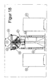
- Fig. 17 and 18 a preferred embodiment of a sorting unit is shown.
- Fig. 17 shows two successive sorting units 51 and 53, according to the first two sorting points according to Fig. 16 , These are so-called tilting filter units which are cascaded, ie arranged one after the other.
- the tilting sorters are electrically and / or logically connected with each other and of course with the reverse vending machine, which the Kippsorter 51 respectively 53, as in Fig. 17 displayed, activated or communicated with them.
- the connection between tipping sorters and reverse vending machines can also take place wirelessly if necessary, for example by means of a so-called WLAN connection.
- Each tilt sorter transports the object in normal position by means of a treadmill 63 on to the next tilt sorter, if the object of this sorting unit is not assigned.
- the object is tilted by a pivoting mechanism either to the right or to the left depending on the given sorting path.
- the operation of the proposed Kippsorter is based on the two Fig. 17 and 18 explained in more detail, wherein Fig. 18 shows the sorting unit 51 in cross section.
- the conveyor belt 63 which is part of the tilting unit 64, is pivoted either to the left or to the right by means of a tilting motor 67 in such a way that the object is either in the container 52 or in the container 52 '. slip.
- the conveyor belt 63 is stopped by switching off the drive motor 65 and the angle of inclination must be large enough to prevent slippage of the object in the container provided 52 or 52 'safe.
- the tilting unit 64 is swung back again to pivot the conveyor belt 63 back into the conveying plane.
- This may be horizontal or slightly inclined, depending on the objects to be conveyed, requirements for the promotion, etc.
- the control of the tilting unit may for example be arranged in a control cabinet 69, which together with the tilting and transport mechanism by a frame 61 worn or is held.
- the light guides are advantageously mounted on the front and / or rear of the tilting sorter.
- the exact position of the object can also be tracked on the belt, if one additionally uses a position encoder on the treadmill motor 65. So that the tape goes back to the horizontal or the desired operating tilt after pivoting, the swing motor is advantageously equipped with a position encoder.
- the length of the object is advantageously recorded in the receiving station 100.
- This length can be determined, for example, by detecting the distance covered during which the object, for example, a light beam 13 (FIG. Fig. 4 ) interrupts. This interruption then gives the longitudinal extent of the object.
- the thus determined longitudinal extent is then the sorting unit transmitted.
- the respective sorting unit By means of the respectively arranged on the corresponding sorting unit light guide and the position decoder from the drive motor position determination can be made to the respective sorting unit, ie due to the detected length can be determined exactly at which position of the respective sorting unit, the object is to be led away. This makes it possible to tilt away in one and the same container, for example, at one end small books and big books at the other end.
- the control of the individual sorting units can be carried out centrally by the individual sorting units are controlled directly from the return device. That is, position sensors monitor the motion of each object on the sorting machine and provide the information to the take-back assembly, and that the take-back assembly directly triggers the actions on each sorting unit to properly process the input or sorted object being transported, e.g. tilt to the right, left, transport to the next sorting unit, etc.
- the individual sorting units are equipped with more intelligence, so that they can autonomously / autonomously take on and handle tasks.
- this is thus a decentralized control or a decentralized mode.
- the return arrangement respectively the interrogators 2 and / or 5, respectively the sensor 6, can eg sorting information, the object 9 concerning the first sorting unit 51 when the object 9 arrives at this unit.
- This information may include, for example: Left sorting at sorting unit 55, object length 30cm, etc.
- the sorting unit 51 independently knows what should happen to the object, respectively what has to be done on this sorting unit.
- the object is further conveyed to the subsequent sorting unit 53, the sorting information being passed on to this unit.
- sorting unit 53 further conveys object 9 to sorting unit 55 and also transmits to it the corresponding sorting information.
- sorting unit 55 respectively the sorter 55, then the left sorting is triggered as soon as the object 9 has taken the correct position on this unit.
- the take-back arrangement transmits not only sorting information to the first sorting unit, but to all connected sorting units. By means of information about the sequence of movements that the sorting units exchange with one another, the sorting units can then autonomously provide for themselves or in their entirety for the correct or predetermined action.
- the sorting units can be interconnected with each other as well as with the take-back arrangement, in particular the interrogator 2 and / or 5 and / or the sensor 6, or it can be a wireless Connection can be used, such as WLAN (Wireless Local Area Network).
- WLAN Wireless Local Area Network
- a variety of cabling and / or protocols can be used.
- One possibility is to equip the return device with a microprocessor card, which is connected by a serial RS232 connection and / or a so-called CAN bus to the microprocessors for controlling the tilting sorter.
- the logic / control components or the microprocessor controlling the arrangement and / or the microprocessors can of course also be mounted outside the take-back arrangement or the housing.
- the number of objects whose codes or labels meet the requirements are displayed on a display, for example, and the user or the consumer can check whether the number detected by the interrogator matches his ideas. If so, it can confirm the detected number and, accordingly, the acceptance process continues as described above with reference to the various figures. However, if the idea of the consumer or user does not match the information, the latter has the option of not confirming the assumption on which all objects, or for example a bottle arrest, have to be removed from the system and the delivery mechanism does not even start up taken or the harass is returned to the consumer.
- the acceptance speed of the return system can be significantly impaired ,
- the return station has to retrieve information from the database of an external server for each returned object and interpret what, in the case of bad response times, for example in the EDP network or on the Internet, can lead to unreasonable waiting times for the customer.
- pledged objects it need not necessarily be reusable items, but the arrangement described according to the invention is also suitable for disposable objects, which should be returned to a suitable location, for example, for environmental reasons. With the arrangement defined according to the invention or the method, however, it can also be prevented that objects that are no longer used by depositing waste fees are deposited wild. Due to a raised deposit, it is worthwhile in any case to return an object to the appropriate, intended collection point instead of wild disposal, such as, for example, to a proposed for the return of such objects inventive arrangement. For example, when selling a TV, a deposit may be charged, which will be at least partially refunded if the TV is returned and disposed of in the appropriate designated location if the TV is no longer in use.
- a keyboard may be provided in which the consumer can enter how to pay or use the pledge.
- the present invention is by no means limited to any particular object or type of deposit or lending, but can be applied wherever a unique identification or designation of a returned or a returned object is necessary, resp. Return, proper disposal or re-cyclization of a given object is desirable or useful or necessary.
Landscapes
- Physics & Mathematics (AREA)
- General Physics & Mathematics (AREA)
- Engineering & Computer Science (AREA)
- Multimedia (AREA)
- Warehouses Or Storage Devices (AREA)
- Sorting Of Articles (AREA)
- Discharge Of Articles From Conveyors (AREA)
- Transition And Organic Metals Composition Catalysts For Addition Polymerization (AREA)
- Photovoltaic Devices (AREA)
- Sanitary Device For Flush Toilet (AREA)
Claims (27)
- Dispositif pour le retour d'objets consignés ou aptes à être consignés (9) et/ou d'objets (9) appartenant à un système de prêt et pourvus d'au moins un code d'identification lisible, avec- une zone de réception (1) pour l'entrée ou le positionnement des objets (9) à rapporter,- un lecteur (2) pour constater l'appartenance de l'objet à une consigne ou à un système de prêt définis,- un dispositif de transport (3) qui est en relation fonctionnelle avec le lecteur de telle sorte qu'en cas de constatation positive de l'appartenance de l'objet, le transport de celui-ci se poursuive,- et un capteur d'identification (5) destiné à identifier l'objet (9) rapporté et, dans le cas d'un objet consigné, à saisir le montant correspondant de la consigne ou, dans le cas d'un système de prêt, à enregistrer le retour de l'objet ou l'objet lui-même,caractérisé en ce que la zone de réception du dispositif comporte une chambre en forme de sas (46) dans laquelle l'objet (9) à détecter peut être placé et dans laquelle l'appartenance de l'objet peut être constatée à l'aide du lecteur (2), et en ce qu'il est prévu au niveau de la chambre en forme de sas (46) au moins deux parois de chambre ou organes de fermeture (44, 47) aptes à être refermés, qui sont en relation fonctionnelle de telle sorte qu'il y ait toujours au moins un organe de fermeture de fermé et que lors d'une constatation ou reconnaissance positive de l'objet par le lecteur (2), l'organe de fermeture (47) monté en aval du sas en forme de chambre (46) puisse être déverrouillé afin de permettre la poursuite du transport de l'objet (9) qui est identifiable par le capteur d'identification (5).
- Dispositif selon la revendication 1, caractérisé en ce qu'il est prévu au niveau des organes de fermeture (44, 47) des moyens tels qu'un élément de verrouillage, un système de fermeture automatique ou autre pour rendre difficile, au moins, un mouvement arrière de l'objet après son passage.
- Dispositif selon la revendication 1 ou 2, caractérisé en ce qu'il est prévu au niveau des organes de fermeture (44, 47) des moyens de contrôle (15) tels que des barrières photoélectriques, des capteurs de pression, des capteurs de position, etc. pour commander l'organe de fermeture (4, 27) et pour détecter un mouvement arrière de l'objet.
- Dispositif selon l'une des revendications 1 à 3, caractérisé en ce que les organes de fermeture (44, 47) comportent un élément pivotant.
- Dispositif selon la revendication 3 ou 4, caractérisé en ce que les moyens de contrôle (15) prévus dans la zone des organes de fermeture (44, 47) comprennent au moins un capteur de position tel qu'une barrière photoélectrique ou un capteur de pression, etc. qui indique si un objet se trouve dans la zone des organes de fermeture et qui détecte par ailleurs si l'objet est arrêté ou est déplacé vers l'arrière.
- Dispositif selon la revendication 4 ou 5, caractérisé en ce que le capteur d'identification (5) contient en supplément un dispositif d'écriture pour modifier éventuellement des données sur un code ou une étiquette réinscriptible, comme une étiquette RFID, disposés sur l'objet ou pour transférer ces données sur le code ou sur l'étiquette.
- Dispositif selon l'une des revendications 1 à 6, caractérisé en ce que le lecteur (2) et le capteur d'identification (5) ou éventuellement le dispositif d'écriture lisent/saisissent ou transmettent les données dans la zone des radiofréquences.
- Dispositif selon l'une des revendications 1 à 7, caractérisé en ce qu'il est prévu dans la zone du capteur d'identification (5) ou éventuellement après celle-ci, dans le sens de transport, une zone de sortie pour l'objet identifié ou enregistré, dans laquelle est prévu au moins un autre capteur de position (11) pour détecter la sortie de l'objet vers un endroit suivant ou pour constater un mouvement arrière d'un objet.
- Dispositif selon la revendication 8, caractérisé en ce qu'il est prévu dans la zone de sortie un autre organe de fermeture (74) pour détecter ou empêcher un mouvement arrière de l'objet.
- Dispositif selon la revendication 8 ou 9, caractérisé en ce qu'il est prévu dans la zone de sortie un dispositif de coupe (32) qui, lors du transport d'un objet dans le sens de transport, est apte à être escamoté ou éloigné par pivotement et qui, lors du transport de l'objet en sens inverse, est apte à être activé par exemple à l'aide d'un ressort pour couper des accessoires de reprise tels que des ficelles, des câbles et autres destinés à transporter l'objet en sens inverse.
- Dispositif selon l'une des revendications 1 à 10, caractérisé en ce qu'il est prévu une alarme qui est apte à être activée en cas d'utilisation abusive du dispositif.
- Dispositif selon l'une des revendications 1 à 11, caractérisé en ce qu'il est prévu à la suite de la zone de réception (1) un dispositif de tri qui comporte une ou plusieurs unités de tri (51, 53, 55) pour trier les objets rapportés.
- Dispositif selon la revendication 12, caractérisé en ce que l'installation de tri comprend des unités de tri (51, 53, 55) qui ont de préférence un fonctionnement très largement autonome et qui comportent chacune une bande transporteuse (63), de préférence entraînée par son propre moteur d'entraînement (65), étant précisé qu'il est prévu, associé à chaque zone de tri, au moins un capteur pour détecter l'objet et éventuellement sa position, et que, de préférence, chaque capteur et/ou une commande d'unité de tri sont reliés électriquement et/ou logiquement, éventuellement sans fil, par exemple par WLAN (réseau local sans fil), au moins au dispositif de retour ou à un lecteur (2) et/ou à un capteur d'identification (5).
- Dispositif selon la revendication 12 ou 13, caractérisé en ce que, de préférence, chaque unité de tri est pourvue d'un lecteur ou interrogateur RFID et/ou d'au moins un capteur de lumière et/ou d'un codeur de position, disposés sur le moteur d'entraînement de chaque unité de tri.
- Installation selon l'une des revendications 12 à 14, caractérisée en ce que chaque unité de tri comprend au moins ce qu'on appelle une unité trieuse à bascule, étant précisé que s'il y en a plusieurs, ces unités sont disposées en cascade, c'est-à-dire les unes derrière les autres.
- Dispositif selon la revendication 15, caractérisé en ce que sur chaque trieuse à bascule, la bande transporteuse respective est apte à pivoter soit vers la gauche, soit vers la droite, vue dans le sens de transport, de manière à évacuer un objet disposé sur ladite bande transporteuse soit vers la gauche, soit vers la droite, par exemple vers un conteneur ou un récipient (52, 52').
- Dispositif selon la revendication 15 ou 16, caractérisé en ce que le moteur (65) de chaque bande transporteuse (23) de chaque trieuse à bascule ainsi qu'un moteur de basculement (27) prévu pour l'inclinaison sont pourvus d'un codeur de position ou sont reliés à un codeur de position afin de pouvoir détecter la position de l'objet sur la bande et l'angle de pivotement ou de rappel à choisir pour faire pivoter la bande transporteuse et la faire revenir à la position de départ.
- Dispositif selon l'une des revendications 15 à 17, caractérisé en ce qu'il est prévu dans la zone de réception (1), sur le dispositif de transport (3), en plus du lecteur (2), un conducteur de lumière (11) et un codeur de position pour détecter la longueur de l'objet rapporté, afin de transmettre la longueur mesurée à une commande, sur l'unité de tri respective, en vue du tri ou du basculement de l'objet rapporté, dans la bonne position.
- Dispositif selon l'une des revendications 12 à 18, caractérisé en ce que les unités de tri (51, 53, 55) sont reliées logiquement et/ou électroniquement entre elles et au dispositif de retour et, ainsi, au lecteur (2), la liaison pouvant se faire à l'aide d'un bus CAN.
- Dispositif selon l'une des revendications 1 à 19, caractérisé en ce que le dispositif de retour et ainsi, fonctionnellement, les unités de tri sont pourvus d'une banque de données ou sont reliés à une banque de données locale dans laquelle sont stockées les données importantes pour le dispositif ou pour le poste de retour et/ou les données d'objets empruntés ou sortis.
- Procédé pour le retour d'objets consignés ou aptes à être consignés (9) et/ou d'objets appartenant à un système de prêt et pourvus d'au moins un code d'identification lisible, caractérisé en ce que l'objet est tout d'abord introduit, à travers une paroi de chambre ou un organe de fermeture, dans la zone de réception, dans une chambre en forme de sas qui est prévue pour l'introduction ou le positionnement des objets à rapporter et pour la constatation, à l'aide d'un lecteur, de l'appartenance de l'objet à une consigne ou à un système de prêt définis, après quoi un dispositif de transport en relation fonctionnelle avec le lecteur est activé en cas de constatation positive de l'appartenance de l'objet, en vue de l'évacuation de l'objet grâce à un deuxième organe de fermeture qui, lors de ladite constatation positive, est déverrouillé et ouvert par le lecteur pour faire passer l'objet, et en ce que l'objet rapporté est identifié à l'aide d'un autre capteur d'identification en vue de la détection par exemple du montant correspondant de la consigne, dans le cas d'un objet consigné, ou en vue de l'enregistrement du retour de l'objet et éventuellement de l'objet lui-même, dans le cas d'un système de prêt, la paroi de la chambre ou l'organe de fermeture et le deuxième organe de fermeture étant en relation fonctionnelle de telle sorte qu'il y ait toujours au moins un organe de fermeture de fermé.
- Procédé selon la revendication 21 pour la réception ou le retour de plusieurs objets et/ou d'un objet contenant plusieurs unités d'objet, caractérisé en ce que le lecteur détecte le nombre d'objets reçus et fournit une indication visuelle et/ou acoustique de ce nombre, après quoi la personne qui introduit les objets ou les unités, telle que le consommateur, confirme ou refuse le nombre détecté et, en cas de refus, le transport et le traitement de l'objet et/ou des unités sont interrompus et/ou l'objet est rendu à la personne telle que le consommateur.
- Procédé selon la revendication 21 ou 22, caractérisé en ce que l'objet ou les objets reçus sont détectés à l'aide des données identifiant exclusivement l'objet en question, telles que le numéro de série, le code d'identification, etc., ces données sont stockées dans une liste négative, c'est-à-dire une liste d'objets dont la réception n'est plus autorisée, et ces données sont éventuellement comparées ou échangées avec d'autres dispositifs de retour, la durée de validité des enregistrements dans la liste négative étant définie suivant l'utilisation recherchée.
- Procédé selon l'une des revendications 21 à 23, caractérisé en ce que dans le cas où, pour vérifier que la réception de l'objet introduit dans le poste de réception est autorisée ou pour fixer un tri ultérieur de l'objet, les données d'une banque de données extérieur sont consultées, pour raccourcir la consultation des données ou dans le cas de mauvais temps de réponse dans un réseau informatique ou éventuellement si temporairement il n'y a pas de liaison, le dispositif de retour ou la zone de réception peut fonctionner en mode hors ligne grâce au fait que des informations de la banque de données extérieure qui concernent tous les objets et qui sont enregistrées dans cette banque de données, ou bien toutes les informations concernant les objets prêtés/sortis sont téléchargées périodiquement sur une banque de données de retour locale au niveau du dispositif de retour.
- Procédé selon l'une des revendications 21 à 24, caractérisé en ce que l'objet ou les objets, en cas de constatation positive par le lecteur, sont transférés sur un dispositif de tri comportant une ou plusieurs unités de tri, en vue du tri des objets rapportés ou reçus, et en ce que les unités de tri individuelles sont commandées par le dispositif de retour ou par le lecteur de telle sorte qu'une éventuelle action de tri soit déclenchée au niveau de l'unité de tri correspondante afin de traiter ou d'éliminer au niveau de ladite unité de tri correspondante l'objet ou les objets à trier.
- Procédé selon l'une des revendications 21 à 25, caractérisé en ce qu'il est prévu sur l'une au moins des unités de tri une commande intelligente et en ce que ces unités de tri ont un fonctionnement en grande partie autonome, de telle sorte que le dispositif de retour ou le lecteur transmet les informations de tri concernant un objet à traiter aux unités de tri et qu'à l'aide des informations de tri l'objet est traité ou éliminé de manière autonome au niveau de l'unité de tri correspondante ou est transmis à une autre unité de tri.
- Utilisation du dispositif selon l'une des revendications 1 à 20 pour un système de prêt tel qu'un système de bibliothèque pour le prêt de livres, de CD, de cassettes, de vidéos, de cartes routières, de magazines, etc.
Priority Applications (1)
| Application Number | Priority Date | Filing Date | Title |
|---|---|---|---|
| EP03794744A EP1540604B1 (fr) | 2002-09-16 | 2003-08-26 | Point de recuperation d'objets consignes ou empruntes |
Applications Claiming Priority (4)
| Application Number | Priority Date | Filing Date | Title |
|---|---|---|---|
| EP02020738 | 2002-09-16 | ||
| EP02020738A EP1398738A1 (fr) | 2002-09-16 | 2002-09-16 | Dispositif de reprise pour des articles consignés ou loués |
| EP03794744A EP1540604B1 (fr) | 2002-09-16 | 2003-08-26 | Point de recuperation d'objets consignes ou empruntes |
| PCT/CH2003/000576 WO2004025579A1 (fr) | 2002-09-16 | 2003-08-26 | Point de recuperation d'objets consignes ou empruntes |
Publications (2)
| Publication Number | Publication Date |
|---|---|
| EP1540604A1 EP1540604A1 (fr) | 2005-06-15 |
| EP1540604B1 true EP1540604B1 (fr) | 2009-10-07 |
Family
ID=31725440
Family Applications (2)
| Application Number | Title | Priority Date | Filing Date |
|---|---|---|---|
| EP02020738A Withdrawn EP1398738A1 (fr) | 2002-09-16 | 2002-09-16 | Dispositif de reprise pour des articles consignés ou loués |
| EP03794744A Expired - Lifetime EP1540604B1 (fr) | 2002-09-16 | 2003-08-26 | Point de recuperation d'objets consignes ou empruntes |
Family Applications Before (1)
| Application Number | Title | Priority Date | Filing Date |
|---|---|---|---|
| EP02020738A Withdrawn EP1398738A1 (fr) | 2002-09-16 | 2002-09-16 | Dispositif de reprise pour des articles consignés ou loués |
Country Status (8)
| Country | Link |
|---|---|
| US (2) | US20060016737A1 (fr) |
| EP (2) | EP1398738A1 (fr) |
| CN (1) | CN1682252A (fr) |
| AT (1) | ATE445207T1 (fr) |
| AU (2) | AU2003250726A1 (fr) |
| CA (1) | CA2497170A1 (fr) |
| DE (1) | DE50312006D1 (fr) |
| WO (1) | WO2004025579A1 (fr) |
Families Citing this family (47)
| Publication number | Priority date | Publication date | Assignee | Title |
|---|---|---|---|---|
| US7329824B2 (en) * | 2003-09-26 | 2008-02-12 | First Data Corporation | Mail processing system and method |
| DE102004058562A1 (de) * | 2004-12-03 | 2006-06-14 | Deutsche Post Ag | Verfahren und Vorrichtung zur Annahme von elektronischen Geräten |
| FI117472B (fi) * | 2004-12-15 | 2006-10-31 | Jestron Oy | Menetelmä ja laite kirjan kannen auki pitämiseksi |
| EP1752935A1 (fr) * | 2005-07-30 | 2007-02-14 | Adaxys SA | Etiquette de consigne et récupératrice automatique avec des étiquettes de consigne |
| DE102005041221A1 (de) * | 2005-08-31 | 2007-03-01 | Krones Ag | Herstellung von Etiketten mit RFID-Transpondern |
| DE102005046102A1 (de) * | 2005-09-27 | 2007-04-05 | Wincor Nixdorf International Gmbh | Verfahren und Vorrichtung zur Eingabe einer PIN |
| NO323842B1 (no) * | 2006-02-28 | 2007-07-09 | Tomra Systems Asa | Fremgangsmate og anordning for overstyring av returautomat |
| DE202007001682U1 (de) * | 2007-02-06 | 2008-03-20 | Wincor Nixdorf International Gmbh | Leergutrücknahmeautomat |
| US20090182566A1 (en) * | 2008-01-10 | 2009-07-16 | Kulvir Singh Bhogal | Automatic Library Referral System and Method |
| WO2010034348A1 (fr) * | 2008-09-26 | 2010-04-01 | Trion Ag | Station de reprise pour milieux de bibliothèque |
| JP2012504832A (ja) | 2008-10-02 | 2012-02-23 | ボールズ、マーク | デバイスに対する二次市場およびベンディングシステム |
| US7881965B2 (en) | 2008-10-02 | 2011-02-01 | ecoATM, Inc. | Secondary market and vending system for devices |
| US11010841B2 (en) | 2008-10-02 | 2021-05-18 | Ecoatm, Llc | Kiosk for recycling electronic devices |
| US10853873B2 (en) | 2008-10-02 | 2020-12-01 | Ecoatm, Llc | Kiosks for evaluating and purchasing used electronic devices and related technology |
| DE102009022621A1 (de) * | 2009-05-27 | 2010-12-02 | Envipco Holding N.V. | Einheit für Behälter-Rücknahmeautomaten |
| DE102009024541A1 (de) * | 2009-06-10 | 2010-12-16 | Wincor Nixdorf International Gmbh | Sperrvorrichtung für Leergutautomat und entsprechender Leergutautomat |
| RU2469395C2 (ru) * | 2010-03-11 | 2012-12-10 | НЕКОММЕРЧЕСКОЕ ПАРТНЕРСТВО "Международный центр трансфера технологий" НП "МЦТТ" | Комплекс устройств для самостоятельного возврата выданных объектов |
| US20140266612A1 (en) * | 2013-03-12 | 2014-09-18 | Novatel Wireless, Inc. | Passive near field id for correlating asset with mobile tracker |
| CA3074916A1 (fr) | 2014-10-02 | 2016-04-07 | Ecoatm, Llc | Application pour l'evaluation de dispositif et d'autres procedes associes au recyclage de dispositif |
| EP3201846B1 (fr) | 2014-10-02 | 2024-07-03 | ecoATM, LLC | Kiosque activé sans fil pour le recyclage de dispositifs de consommateurs |
| US10445708B2 (en) | 2014-10-03 | 2019-10-15 | Ecoatm, Llc | System for electrically testing mobile devices at a consumer-operated kiosk, and associated devices and methods |
| WO2016069738A1 (fr) | 2014-10-31 | 2016-05-06 | ecoATM, Inc. | Systèmes et procédés pour recycler des dispositifs électroniques grand public |
| US20170169401A1 (en) | 2015-12-11 | 2017-06-15 | ecoATM, Inc. | Systems and methods for recycling consumer electronic devices |
| WO2016094789A1 (fr) | 2014-12-12 | 2016-06-16 | ecoATM, Inc. | Systèmes et procédés pour le recyclage de dispositifs électroniques grand public |
| CN105057221B (zh) * | 2015-09-18 | 2017-07-21 | 苏州萨伯工业设计有限公司 | 一种稀土合金棒料残缺自动投影分选方法 |
| US10269110B2 (en) | 2016-06-28 | 2019-04-23 | Ecoatm, Llc | Methods and systems for detecting cracks in illuminated electronic device screens |
| US20180047006A1 (en) * | 2016-08-11 | 2018-02-15 | Wal-Mart Stores, Inc. | Automated store return process |
| US20190251522A1 (en) * | 2018-02-09 | 2019-08-15 | Green Grubbox Llc | Reusable food or beverage related product management system |
| AU2019373673B2 (en) * | 2018-10-31 | 2025-01-09 | Tomra Systems Asa | Reverse vending machine arrangements and related methods |
| CN109686015B (zh) * | 2018-11-30 | 2021-08-03 | 广东拓迪智能科技有限公司 | 一种无人智慧图书馆中图书借阅管理方法及系统 |
| US11989710B2 (en) | 2018-12-19 | 2024-05-21 | Ecoatm, Llc | Systems and methods for vending and/or purchasing mobile phones and other electronic devices |
| US12322259B2 (en) | 2018-12-19 | 2025-06-03 | Ecoatm, Llc | Systems and methods for vending and/or purchasing mobile phones and other electronic devices |
| WO2020167846A1 (fr) | 2019-02-12 | 2020-08-20 | Ecoatm, Llc | Kiosque pour évaluer et acheter des dispositifs électroniques usagés |
| WO2020167849A1 (fr) | 2019-02-12 | 2020-08-20 | Ecoatm, Llc | Support de connecteur pour kiosque de dispositif électronique |
| US11798250B2 (en) | 2019-02-18 | 2023-10-24 | Ecoatm, Llc | Neural network based physical condition evaluation of electronic devices, and associated systems and methods |
| CN110902210B (zh) * | 2019-12-16 | 2022-04-08 | 何雨庭 | 一种小型家用垃圾自动分类机 |
| US12380420B2 (en) | 2019-12-18 | 2025-08-05 | Ecoatm, Llc | Systems and methods for vending and/or purchasing mobile phones and other electronic devices |
| WO2022040668A1 (fr) | 2020-08-17 | 2022-02-24 | Ecoatm, Llc | Évaluation d'un dispositif électronique à l'aide d'une reconnaissance optique de caractères |
| US12271929B2 (en) | 2020-08-17 | 2025-04-08 | Ecoatm Llc | Evaluating an electronic device using a wireless charger |
| US12475756B2 (en) | 2020-08-17 | 2025-11-18 | Ecoatm, Llc | Connector carrier for electronic device kiosk |
| US11922467B2 (en) | 2020-08-17 | 2024-03-05 | ecoATM, Inc. | Evaluating an electronic device using optical character recognition |
| US20220068076A1 (en) * | 2020-08-25 | 2022-03-03 | Ecoatm, Llc | Kiosk for evaluating and purchasing used electronic devices |
| CA3193151A1 (fr) | 2020-08-25 | 2022-03-03 | Ecoatm, Llc | Evaluation et recyclage de dispositifs electroniques |
| WO2022133498A1 (fr) * | 2020-12-17 | 2022-06-23 | Ecoatm, Llc | Systèmes et procédés de vente et/ou d'achat de téléphones mobiles et d'autres dispositifs électroniques |
| WO2023283647A1 (fr) | 2021-07-09 | 2023-01-12 | Ecoatm, Llc | Identification de dispositifs électroniques à l'aide d'informations à variations temporelles |
| NO347847B1 (en) * | 2022-09-22 | 2024-04-15 | Grin As | Reverse vending machine and method in a reverse vending machine |
| EP4361979A1 (fr) * | 2022-10-25 | 2024-05-01 | RE DEPOSIT Solutions GmbH | Dispositif de traitement et support lisible par ordinateur comprenant des instructions pour un dispositif de traitement |
Family Cites Families (21)
| Publication number | Priority date | Publication date | Assignee | Title |
|---|---|---|---|---|
| US3627094A (en) * | 1968-12-16 | 1971-12-14 | Bally Mfg Corp | Coin chute guard means |
| CH536531A (de) * | 1971-09-27 | 1973-04-30 | Sodeco Compteurs De Geneve | Vorrichtung zur Sicherung von Münzkassierautomaten gegen betrügerische Handlungen |
| JPS5315894A (en) * | 1976-07-28 | 1978-02-14 | Mars Inc | Coin examining system |
| US4245731A (en) * | 1977-09-23 | 1981-01-20 | Herbst Richard J | Apparatus for beverage container recovery and deposit refund system |
| GB1600400A (en) * | 1977-10-13 | 1981-10-14 | Ti Fords Ltd | Bottle inspection apparatus |
| US4440284A (en) * | 1980-05-09 | 1984-04-03 | Environmental Products Corporation | Automated aluminum can redemption center for direct return deposit payout |
| GB2102174A (en) * | 1981-07-18 | 1983-01-26 | Carol Anne Rees | Waste item recovery devices |
| US4653627A (en) * | 1985-08-26 | 1987-03-31 | Can And Bottle Systems, Inc. | Reverse vending machine |
| CA2106098C (fr) * | 1991-03-14 | 1996-07-02 | Shigeru Handa | Systeme de controle de stocks d'articles |
| US5630493A (en) * | 1992-03-16 | 1997-05-20 | Environmental Products Corporation | Acceptance assembly for a reverse vending machine |
| DE59600574D1 (de) * | 1995-02-24 | 1998-10-22 | Ascom Autelca Ag Guemligen | Verfahren und vorrichtung zur gesicherten ablage und ausgabe von banknoten |
| NO302739B1 (no) * | 1996-07-12 | 1998-04-20 | Tomra Systems Asa | Sorteringsanordning for returautomat |
| US5906260A (en) * | 1997-07-03 | 1999-05-25 | Lucent Technologies Inc. | Anti-fraud coin chute device |
| EP0923055A1 (fr) * | 1997-12-14 | 1999-06-16 | Prokent AG | Système automatisé avec fonction de chargement de sources de courant réutilisables |
| ID29288A (id) * | 1998-06-08 | 2001-08-16 | St Logitrack Pte Ltd Cs | Sistem pengawasan |
| FR2785702B3 (fr) * | 1998-11-06 | 2000-10-13 | Distributoor | Perfectionnement aux systemes d'identification par redondance de lecture dans les appareils de deconsignation |
| DE19910334A1 (de) * | 1999-03-09 | 2000-09-14 | Linnemann Alfons | Leergutrücknahmesystem für die automatische Rückgabe von Leergutgetränkekästen |
| US20020063033A1 (en) * | 2000-11-30 | 2002-05-30 | Gad Ben-Naim | System and method for exchanging of at least one item |
| DE10063368A1 (de) * | 2000-12-19 | 2002-06-20 | Klaus Rudolph | Vorrichtung zum Sortieren und/oder Sammeln von Materialien |
| FR2821195B1 (fr) * | 2001-02-19 | 2003-04-18 | Distributoor Sa | Perfectionnement a un appareil de deconsignation |
| US20030010598A1 (en) * | 2001-05-09 | 2003-01-16 | Kiva Kris M. | Recycling machine with container compacting system |
-
2002
- 2002-09-16 EP EP02020738A patent/EP1398738A1/fr not_active Withdrawn
-
2003
- 2003-08-26 CN CNA038218607A patent/CN1682252A/zh active Pending
- 2003-08-26 DE DE50312006T patent/DE50312006D1/de not_active Expired - Lifetime
- 2003-08-26 WO PCT/CH2003/000576 patent/WO2004025579A1/fr not_active Ceased
- 2003-08-26 AT AT03794744T patent/ATE445207T1/de active
- 2003-08-26 EP EP03794744A patent/EP1540604B1/fr not_active Expired - Lifetime
- 2003-08-26 US US10/526,179 patent/US20060016737A1/en not_active Abandoned
- 2003-08-26 AU AU2003250726A patent/AU2003250726A1/en not_active Abandoned
- 2003-08-26 CA CA002497170A patent/CA2497170A1/fr not_active Abandoned
-
2008
- 2008-07-23 US US12/178,076 patent/US20080277467A1/en not_active Abandoned
-
2010
- 2010-07-15 AU AU2010203005A patent/AU2010203005A1/en not_active Abandoned
Also Published As
| Publication number | Publication date |
|---|---|
| AU2003250726A1 (en) | 2004-04-30 |
| AU2010203005A1 (en) | 2010-08-05 |
| CN1682252A (zh) | 2005-10-12 |
| EP1398738A1 (fr) | 2004-03-17 |
| CA2497170A1 (fr) | 2004-03-25 |
| DE50312006D1 (de) | 2009-11-19 |
| WO2004025579A1 (fr) | 2004-03-25 |
| ATE445207T1 (de) | 2009-10-15 |
| US20060016737A1 (en) | 2006-01-26 |
| EP1540604A1 (fr) | 2005-06-15 |
| US20080277467A1 (en) | 2008-11-13 |
Similar Documents
| Publication | Publication Date | Title |
|---|---|---|
| EP1540604B1 (fr) | Point de recuperation d'objets consignes ou empruntes | |
| DE69730876T2 (de) | Verfahren und Vorrichtung zum Bestimmen der Bewegungsrichtung von Flüssigkeitsbehälter | |
| DE69409851T2 (de) | Gerät zum Deponieren von Dokumenten | |
| DE69220933T2 (de) | System und verfahren zum versenden und einsammeln von postartikeln | |
| EP1386293B1 (fr) | Identification d'un objet dote d'une consigne | |
| DE69317653T2 (de) | Automatisches kassiersystem | |
| DE69725011T2 (de) | Sicherheitsberechtigungsschein für elektronische sperrvorrichtung in verkaufsautomaten | |
| DE3127167C2 (de) | Einrichtung zum Ausscheiden von Banknoten für einen automatischen Geldausgabe-Bankschalter | |
| DE3524231A1 (de) | Vorrichtung und verfahren zur erfassung und abfertigung von zum kauf ausgewaehlten artikeln mit maschinenlesbaren unterscheidbaren identifizierungscodes | |
| DE602005003641T2 (de) | Paketfrankierungseinrichtung und verfahren dafür | |
| EP1636770B1 (fr) | Distributeur d'objets | |
| EP0727078B1 (fr) | Terminal de distribution automatique de caisses de boissons | |
| EP0429623B1 (fr) | Dispositif pour la saisie de marchandises du cote de la clientele | |
| DE19707156A1 (de) | Warenschleuse für Selbstbedienungsläden | |
| EP0287049B1 (fr) | Procédé de liquidation et d'encaissement de machines automatiques actionnées par pièces de monnaie et installation pour la réalisation de ce procédé | |
| DE102011109392B4 (de) | Warenautomat | |
| EP1280111B1 (fr) | Appareil et procédé pour retourner des articles, en particulier pour retourner des articles de l'industrie de boissons | |
| DE102011106747A1 (de) | Warenausgabeeinrichtung für ein Warenlager, Warenlager mit einer Warenausgabeeinrichtung und Warenvereinzeler für eine Warenausgabeeinrichtung | |
| DE102021129540B4 (de) | Annahme-Verfahren für zurückzunehmendes Leergut und zu versendende Pakete, Paket-Leergut-Annahme-Station sowie Waren-Verkaufs-Filiale hierfür | |
| DE102011110302A1 (de) | Warenlager und Warenlagerungseinheit dafür | |
| EP2026289A1 (fr) | Installation spécialisée ; procédé d'identification d'une personne et choix des fonctions de l'installation spécialisée | |
| DE102004063665A1 (de) | Getränkekisten-Verkaufsanlage | |
| DE20219795U1 (de) | Rücknahmeautomat für bepfandete Einweg-Verpackungen, insbesondere Getränkebehälter | |
| DE20121812U1 (de) | Vorrichtung zur Rücknahme von Gegenständen, insbesondere zur Rücknahme von Gebinden der Getränkeindustrie |
Legal Events
| Date | Code | Title | Description |
|---|---|---|---|
| PUAI | Public reference made under article 153(3) epc to a published international application that has entered the european phase |
Free format text: ORIGINAL CODE: 0009012 |
|
| 17P | Request for examination filed |
Effective date: 20050122 |
|
| AK | Designated contracting states |
Kind code of ref document: A1 Designated state(s): AT BE BG CH CY CZ DE DK EE ES FI FR GB GR HU IE IT LI LU MC NL PT RO SE SI SK TR |
|
| AX | Request for extension of the european patent |
Extension state: AL LT LV MK |
|
| DAX | Request for extension of the european patent (deleted) | ||
| 17Q | First examination report despatched |
Effective date: 20060818 |
|
| GRAP | Despatch of communication of intention to grant a patent |
Free format text: ORIGINAL CODE: EPIDOSNIGR1 |
|
| GRAS | Grant fee paid |
Free format text: ORIGINAL CODE: EPIDOSNIGR3 |
|
| GRAA | (expected) grant |
Free format text: ORIGINAL CODE: 0009210 |
|
| AK | Designated contracting states |
Kind code of ref document: B1 Designated state(s): AT BE BG CH CY CZ DE DK EE ES FI FR GB GR HU IE IT LI LU MC NL PT RO SE SI SK TR |
|
| REG | Reference to a national code |
Ref country code: GB Ref legal event code: FG4D Free format text: NOT ENGLISH |
|
| REG | Reference to a national code |
Ref country code: CH Ref legal event code: NV Representative=s name: TROESCH SCHEIDEGGER WERNER AG Ref country code: CH Ref legal event code: EP |
|
| REG | Reference to a national code |
Ref country code: IE Ref legal event code: FG4D |
|
| REF | Corresponds to: |
Ref document number: 50312006 Country of ref document: DE Date of ref document: 20091119 Kind code of ref document: P |
|
| PG25 | Lapsed in a contracting state [announced via postgrant information from national office to epo] |
Ref country code: SI Free format text: LAPSE BECAUSE OF FAILURE TO SUBMIT A TRANSLATION OF THE DESCRIPTION OR TO PAY THE FEE WITHIN THE PRESCRIBED TIME-LIMIT Effective date: 20091007 |
|
| PG25 | Lapsed in a contracting state [announced via postgrant information from national office to epo] |
Ref country code: FI Free format text: LAPSE BECAUSE OF FAILURE TO SUBMIT A TRANSLATION OF THE DESCRIPTION OR TO PAY THE FEE WITHIN THE PRESCRIBED TIME-LIMIT Effective date: 20091007 Ref country code: SE Free format text: LAPSE BECAUSE OF FAILURE TO SUBMIT A TRANSLATION OF THE DESCRIPTION OR TO PAY THE FEE WITHIN THE PRESCRIBED TIME-LIMIT Effective date: 20091007 Ref country code: ES Free format text: LAPSE BECAUSE OF FAILURE TO SUBMIT A TRANSLATION OF THE DESCRIPTION OR TO PAY THE FEE WITHIN THE PRESCRIBED TIME-LIMIT Effective date: 20100118 Ref country code: PT Free format text: LAPSE BECAUSE OF FAILURE TO SUBMIT A TRANSLATION OF THE DESCRIPTION OR TO PAY THE FEE WITHIN THE PRESCRIBED TIME-LIMIT Effective date: 20100208 |
|
| REG | Reference to a national code |
Ref country code: IE Ref legal event code: FD4D |
|
| PG25 | Lapsed in a contracting state [announced via postgrant information from national office to epo] |
Ref country code: BG Free format text: LAPSE BECAUSE OF FAILURE TO SUBMIT A TRANSLATION OF THE DESCRIPTION OR TO PAY THE FEE WITHIN THE PRESCRIBED TIME-LIMIT Effective date: 20100107 Ref country code: IE Free format text: LAPSE BECAUSE OF FAILURE TO SUBMIT A TRANSLATION OF THE DESCRIPTION OR TO PAY THE FEE WITHIN THE PRESCRIBED TIME-LIMIT Effective date: 20091007 Ref country code: DK Free format text: LAPSE BECAUSE OF FAILURE TO SUBMIT A TRANSLATION OF THE DESCRIPTION OR TO PAY THE FEE WITHIN THE PRESCRIBED TIME-LIMIT Effective date: 20091007 Ref country code: RO Free format text: LAPSE BECAUSE OF FAILURE TO SUBMIT A TRANSLATION OF THE DESCRIPTION OR TO PAY THE FEE WITHIN THE PRESCRIBED TIME-LIMIT Effective date: 20091007 Ref country code: EE Free format text: LAPSE BECAUSE OF FAILURE TO SUBMIT A TRANSLATION OF THE DESCRIPTION OR TO PAY THE FEE WITHIN THE PRESCRIBED TIME-LIMIT Effective date: 20091007 |
|
| PLBE | No opposition filed within time limit |
Free format text: ORIGINAL CODE: 0009261 |
|
| STAA | Information on the status of an ep patent application or granted ep patent |
Free format text: STATUS: NO OPPOSITION FILED WITHIN TIME LIMIT |
|
| PG25 | Lapsed in a contracting state [announced via postgrant information from national office to epo] |
Ref country code: CZ Free format text: LAPSE BECAUSE OF FAILURE TO SUBMIT A TRANSLATION OF THE DESCRIPTION OR TO PAY THE FEE WITHIN THE PRESCRIBED TIME-LIMIT Effective date: 20091007 Ref country code: SK Free format text: LAPSE BECAUSE OF FAILURE TO SUBMIT A TRANSLATION OF THE DESCRIPTION OR TO PAY THE FEE WITHIN THE PRESCRIBED TIME-LIMIT Effective date: 20091007 |
|
| 26N | No opposition filed |
Effective date: 20100708 |
|
| PG25 | Lapsed in a contracting state [announced via postgrant information from national office to epo] |
Ref country code: GR Free format text: LAPSE BECAUSE OF FAILURE TO SUBMIT A TRANSLATION OF THE DESCRIPTION OR TO PAY THE FEE WITHIN THE PRESCRIBED TIME-LIMIT Effective date: 20100108 |
|
| PG25 | Lapsed in a contracting state [announced via postgrant information from national office to epo] |
Ref country code: MC Free format text: LAPSE BECAUSE OF NON-PAYMENT OF DUE FEES Effective date: 20100831 Ref country code: IT Free format text: LAPSE BECAUSE OF FAILURE TO SUBMIT A TRANSLATION OF THE DESCRIPTION OR TO PAY THE FEE WITHIN THE PRESCRIBED TIME-LIMIT Effective date: 20091007 |
|
| PG25 | Lapsed in a contracting state [announced via postgrant information from national office to epo] |
Ref country code: CY Free format text: LAPSE BECAUSE OF FAILURE TO SUBMIT A TRANSLATION OF THE DESCRIPTION OR TO PAY THE FEE WITHIN THE PRESCRIBED TIME-LIMIT Effective date: 20091007 |
|
| PG25 | Lapsed in a contracting state [announced via postgrant information from national office to epo] |
Ref country code: LU Free format text: LAPSE BECAUSE OF NON-PAYMENT OF DUE FEES Effective date: 20100826 Ref country code: HU Free format text: LAPSE BECAUSE OF FAILURE TO SUBMIT A TRANSLATION OF THE DESCRIPTION OR TO PAY THE FEE WITHIN THE PRESCRIBED TIME-LIMIT Effective date: 20100408 |
|
| PG25 | Lapsed in a contracting state [announced via postgrant information from national office to epo] |
Ref country code: TR Free format text: LAPSE BECAUSE OF FAILURE TO SUBMIT A TRANSLATION OF THE DESCRIPTION OR TO PAY THE FEE WITHIN THE PRESCRIBED TIME-LIMIT Effective date: 20091007 |
|
| REG | Reference to a national code |
Ref country code: FR Ref legal event code: PLFP Year of fee payment: 14 |
|
| PGFP | Annual fee paid to national office [announced via postgrant information from national office to epo] |
Ref country code: NL Payment date: 20160830 Year of fee payment: 14 |
|
| PGFP | Annual fee paid to national office [announced via postgrant information from national office to epo] |
Ref country code: CH Payment date: 20160819 Year of fee payment: 14 Ref country code: GB Payment date: 20160819 Year of fee payment: 14 Ref country code: DE Payment date: 20160912 Year of fee payment: 14 |
|
| PGFP | Annual fee paid to national office [announced via postgrant information from national office to epo] |
Ref country code: FR Payment date: 20160831 Year of fee payment: 14 Ref country code: AT Payment date: 20160826 Year of fee payment: 14 |
|
| PGFP | Annual fee paid to national office [announced via postgrant information from national office to epo] |
Ref country code: BE Payment date: 20160825 Year of fee payment: 14 |
|
| REG | Reference to a national code |
Ref country code: DE Ref legal event code: R119 Ref document number: 50312006 Country of ref document: DE |
|
| REG | Reference to a national code |
Ref country code: CH Ref legal event code: PL |
|
| REG | Reference to a national code |
Ref country code: NL Ref legal event code: MM Effective date: 20170901 |
|
| REG | Reference to a national code |
Ref country code: AT Ref legal event code: MM01 Ref document number: 445207 Country of ref document: AT Kind code of ref document: T Effective date: 20170826 |
|
| GBPC | Gb: european patent ceased through non-payment of renewal fee |
Effective date: 20170826 |
|
| PG25 | Lapsed in a contracting state [announced via postgrant information from national office to epo] |
Ref country code: LI Free format text: LAPSE BECAUSE OF NON-PAYMENT OF DUE FEES Effective date: 20170831 Ref country code: CH Free format text: LAPSE BECAUSE OF NON-PAYMENT OF DUE FEES Effective date: 20170831 |
|
| REG | Reference to a national code |
Ref country code: FR Ref legal event code: ST Effective date: 20180430 |
|
| PG25 | Lapsed in a contracting state [announced via postgrant information from national office to epo] |
Ref country code: AT Free format text: LAPSE BECAUSE OF NON-PAYMENT OF DUE FEES Effective date: 20170826 |
|
| REG | Reference to a national code |
Ref country code: BE Ref legal event code: MM Effective date: 20170831 |
|
| PG25 | Lapsed in a contracting state [announced via postgrant information from national office to epo] |
Ref country code: NL Free format text: LAPSE BECAUSE OF NON-PAYMENT OF DUE FEES Effective date: 20170901 |
|
| PG25 | Lapsed in a contracting state [announced via postgrant information from national office to epo] |
Ref country code: DE Free format text: LAPSE BECAUSE OF NON-PAYMENT OF DUE FEES Effective date: 20180301 Ref country code: GB Free format text: LAPSE BECAUSE OF NON-PAYMENT OF DUE FEES Effective date: 20170826 |
|
| PG25 | Lapsed in a contracting state [announced via postgrant information from national office to epo] |
Ref country code: BE Free format text: LAPSE BECAUSE OF NON-PAYMENT OF DUE FEES Effective date: 20170831 Ref country code: FR Free format text: LAPSE BECAUSE OF NON-PAYMENT OF DUE FEES Effective date: 20170831 |