EP1540155B1 - Energy converter - Google Patents
Energy converter Download PDFInfo
- Publication number
- EP1540155B1 EP1540155B1 EP03795541A EP03795541A EP1540155B1 EP 1540155 B1 EP1540155 B1 EP 1540155B1 EP 03795541 A EP03795541 A EP 03795541A EP 03795541 A EP03795541 A EP 03795541A EP 1540155 B1 EP1540155 B1 EP 1540155B1
- Authority
- EP
- European Patent Office
- Prior art keywords
- energy converter
- combustion
- piston
- stroke
- energy
- Prior art date
- Legal status (The legal status is an assumption and is not a legal conclusion. Google has not performed a legal analysis and makes no representation as to the accuracy of the status listed.)
- Expired - Lifetime
Links
Images


Classifications
-
- F—MECHANICAL ENGINEERING; LIGHTING; HEATING; WEAPONS; BLASTING
- F02—COMBUSTION ENGINES; HOT-GAS OR COMBUSTION-PRODUCT ENGINE PLANTS
- F02D—CONTROLLING COMBUSTION ENGINES
- F02D13/00—Controlling the engine output power by varying inlet or exhaust valve operating characteristics, e.g. timing
- F02D13/02—Controlling the engine output power by varying inlet or exhaust valve operating characteristics, e.g. timing during engine operation
- F02D13/0203—Variable control of intake and exhaust valves
- F02D13/0215—Variable control of intake and exhaust valves changing the valve timing only
-
- F—MECHANICAL ENGINEERING; LIGHTING; HEATING; WEAPONS; BLASTING
- F02—COMBUSTION ENGINES; HOT-GAS OR COMBUSTION-PRODUCT ENGINE PLANTS
- F02B—INTERNAL-COMBUSTION PISTON ENGINES; COMBUSTION ENGINES IN GENERAL
- F02B1/00—Engines characterised by fuel-air mixture compression
- F02B1/12—Engines characterised by fuel-air mixture compression with compression ignition
-
- F—MECHANICAL ENGINEERING; LIGHTING; HEATING; WEAPONS; BLASTING
- F02—COMBUSTION ENGINES; HOT-GAS OR COMBUSTION-PRODUCT ENGINE PLANTS
- F02B—INTERNAL-COMBUSTION PISTON ENGINES; COMBUSTION ENGINES IN GENERAL
- F02B71/00—Free-piston engines; Engines without rotary main shaft
- F02B71/02—Starting
-
- F—MECHANICAL ENGINEERING; LIGHTING; HEATING; WEAPONS; BLASTING
- F02—COMBUSTION ENGINES; HOT-GAS OR COMBUSTION-PRODUCT ENGINE PLANTS
- F02B—INTERNAL-COMBUSTION PISTON ENGINES; COMBUSTION ENGINES IN GENERAL
- F02B71/00—Free-piston engines; Engines without rotary main shaft
- F02B71/04—Adaptations of such engines for special use; Combinations of such engines with apparatus driven thereby
-
- F—MECHANICAL ENGINEERING; LIGHTING; HEATING; WEAPONS; BLASTING
- F02—COMBUSTION ENGINES; HOT-GAS OR COMBUSTION-PRODUCT ENGINE PLANTS
- F02D—CONTROLLING COMBUSTION ENGINES
- F02D29/00—Controlling engines, such controlling being peculiar to the devices driven thereby, the devices being other than parts or accessories essential to engine operation, e.g. controlling of engines by signals external thereto
- F02D29/06—Controlling engines, such controlling being peculiar to the devices driven thereby, the devices being other than parts or accessories essential to engine operation, e.g. controlling of engines by signals external thereto peculiar to engines driving electric generators
-
- F—MECHANICAL ENGINEERING; LIGHTING; HEATING; WEAPONS; BLASTING
- F02—COMBUSTION ENGINES; HOT-GAS OR COMBUSTION-PRODUCT ENGINE PLANTS
- F02M—SUPPLYING COMBUSTION ENGINES IN GENERAL WITH COMBUSTIBLE MIXTURES OR CONSTITUENTS THEREOF
- F02M26/00—Engine-pertinent apparatus for adding exhaust gases to combustion-air, main fuel or fuel-air mixture, e.g. by exhaust gas recirculation [EGR] systems
- F02M26/01—Internal exhaust gas recirculation, i.e. wherein the residual exhaust gases are trapped in the cylinder or pushed back from the intake or the exhaust manifold into the combustion chamber without the use of additional passages
-
- F—MECHANICAL ENGINEERING; LIGHTING; HEATING; WEAPONS; BLASTING
- F02—COMBUSTION ENGINES; HOT-GAS OR COMBUSTION-PRODUCT ENGINE PLANTS
- F02N—STARTING OF COMBUSTION ENGINES; STARTING AIDS FOR SUCH ENGINES, NOT OTHERWISE PROVIDED FOR
- F02N11/00—Starting of engines by means of electric motors
- F02N11/02—Starting of engines by means of electric motors the motors having longitudinally-shiftable rotors
-
- F—MECHANICAL ENGINEERING; LIGHTING; HEATING; WEAPONS; BLASTING
- F02—COMBUSTION ENGINES; HOT-GAS OR COMBUSTION-PRODUCT ENGINE PLANTS
- F02N—STARTING OF COMBUSTION ENGINES; STARTING AIDS FOR SUCH ENGINES, NOT OTHERWISE PROVIDED FOR
- F02N11/00—Starting of engines by means of electric motors
- F02N11/04—Starting of engines by means of electric motors the motors being associated with current generators
-
- F—MECHANICAL ENGINEERING; LIGHTING; HEATING; WEAPONS; BLASTING
- F02—COMBUSTION ENGINES; HOT-GAS OR COMBUSTION-PRODUCT ENGINE PLANTS
- F02B—INTERNAL-COMBUSTION PISTON ENGINES; COMBUSTION ENGINES IN GENERAL
- F02B37/00—Engines characterised by provision of pumps driven at least for part of the time by exhaust
-
- F—MECHANICAL ENGINEERING; LIGHTING; HEATING; WEAPONS; BLASTING
- F02—COMBUSTION ENGINES; HOT-GAS OR COMBUSTION-PRODUCT ENGINE PLANTS
- F02B—INTERNAL-COMBUSTION PISTON ENGINES; COMBUSTION ENGINES IN GENERAL
- F02B63/00—Adaptations of engines for driving pumps, hand-held tools or electric generators; Portable combinations of engines with engine-driven devices
- F02B63/04—Adaptations of engines for driving pumps, hand-held tools or electric generators; Portable combinations of engines with engine-driven devices for electric generators
- F02B63/041—Linear electric generators
-
- F—MECHANICAL ENGINEERING; LIGHTING; HEATING; WEAPONS; BLASTING
- F02—COMBUSTION ENGINES; HOT-GAS OR COMBUSTION-PRODUCT ENGINE PLANTS
- F02D—CONTROLLING COMBUSTION ENGINES
- F02D13/00—Controlling the engine output power by varying inlet or exhaust valve operating characteristics, e.g. timing
- F02D13/02—Controlling the engine output power by varying inlet or exhaust valve operating characteristics, e.g. timing during engine operation
- F02D13/0261—Controlling the valve overlap
- F02D13/0265—Negative valve overlap for temporarily storing residual gas in the cylinder
-
- Y—GENERAL TAGGING OF NEW TECHNOLOGICAL DEVELOPMENTS; GENERAL TAGGING OF CROSS-SECTIONAL TECHNOLOGIES SPANNING OVER SEVERAL SECTIONS OF THE IPC; TECHNICAL SUBJECTS COVERED BY FORMER USPC CROSS-REFERENCE ART COLLECTIONS [XRACs] AND DIGESTS
- Y02—TECHNOLOGIES OR APPLICATIONS FOR MITIGATION OR ADAPTATION AGAINST CLIMATE CHANGE
- Y02T—CLIMATE CHANGE MITIGATION TECHNOLOGIES RELATED TO TRANSPORTATION
- Y02T10/00—Road transport of goods or passengers
- Y02T10/10—Internal combustion engine [ICE] based vehicles
- Y02T10/12—Improving ICE efficiencies
Definitions
- the present invention relates to an energy converter according to the preamble of claim 1, a method for operating an energy converter according to the preamble of claim 11, and a method of starting an energy converter according to the preamble of claim 16.
- a free piston engine is characterised in that it does not have a crankshaft.
- Free piston engines can be of a single piston or dual piston layout. In a dual piston layout, there are separate combustion chambers and fuel injection for each piston. The pistons are attached to each other by a rod so that they move simultaneously. Free piston engines are well known in the art.
- a common way of attaining energy from a FPE is to mount an electrical generator to the interconnecting rod.
- HCCI combustion Also well known in the art is the so called HCCI combustion.
- HCCI homogeneous charge compression ignition
- US 6199519 discloses a two-stroke, free piston engine with a linear electrical alternator/generator.
- the engine is driven in an oscillating mode with constant frequency. Fuel and air are introduced in a two-stroke cycle fashion without using valves.
- the engine operates in an HCCI (autoignition) mode and will shut off when not needed and run at essentially constant velocity and power when on. Regulation of the coil current can be used to regulate the piston velocity as to change the compression ratio if the fuel composition is changed.
- the engine/generator is particularly intended for charging batteries in hybrid automobile applications. To start the engine, the batteries are used to operate the linear alternator as a linear motor.
- the piston is oscillated in the cylinder, building to a higher compression each cycle until sufficient compression is developed for autoignition, at which time fuel is introduced to the engine and self powered operation will ensue.
- HCCI is mentioned as a possible combustion principle but there is nothing disclosed on how such a combustion could be controlled. Further, different storing devices, for storing at least a part of the combustion energy, such as capacitors, batteries and flywheels are discussed. Their use is however scarcely described.
- One object of the invention is therefore to provide an energy converter that does not need a large energy storage. This object is achieved by means of a device according to claim 1.
- the invention is characterized in that the energy converter is arranged to adapt its power output depending on the required load of the energy converter. By doing so only a small energy storage is needed. This reduces both the cost and the weight of the energy converter compared to previous solutions. Further, the invention can be operated very efficiently with a very low fuel consumption and very low emissions.
- Ignition points are provided by multiple exothermal centers (ETC) in the gas-mixture. Since HCCI has no flame-propagation, the combustion is instead kinetically controlled. To generate multiple ETCs, it is important to be able to control the homogeneity of temperature and composition in the gas-mixture. The lack of flame-propagation causes the temperature distribution in the combustion chamber after combustion, in contrast to normal flame propagation, to be almost homogeneous. This leads to reduction of NOx emissions from thousands of ppm to an order of ten ppm. The kinetically controlled combustion means that the heat release can be extremely rapid, which makes it theoretically possible to approach the ideal Otto-cycle (constant volume combustion).
- HCCI combustion requires a high dilution of the air/fuel mixture, only the part load portion of the engine operational range can be valid for HCCI combustion (assuming a naturally aspirated engine). If high compression ratios are allowed, the HCCI combustion has the potential to exceed the Diesel engine in efficiency (40 - 45%) without the high NOx and particle emissions.
- One way of realizing a 4-stroke HCCI engine is to emulate the in-cylinder conditions of a 2-stroke engine by trapping large amounts of residual gases. This can be done by closing the exhaust valve early, as described by Kerkau et al ., Denbratt and Willand et al ..
- Another alternative is to manipulate the compression temperature by variable intake valve timing, Smith et al . and Aceves et al., or by a combination of variable compression and variable intake valve timing, Denbratt.
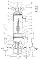
- the energy converter comprises a free piston combustion system 1 that comprises two pistons 2, 3 with separate cylinders 4, 5 and combustion chambers 6, 7. More precisely, the combustion system 1 comprises a first piston 2 arranged in a first cylinder 4 having a first combustion chamber 6 and also comprises a second piston 3 arranged in a second cylinder 5 and having a second combustion chamber 7.
- the first combustion chamber 6 is provided with an additional inlet valve 15'
- the second combustion chamber 7 is provided with an additional inlet valve 17'.
- the energy converter is further provided with e.g. sensors, actuators and a control unit (not shown) which are further described below.
- the first outlet valve 14 is controlled by a first outlet valve control unit 20 and the first inlet valve 15 is controlled by a first inlet valve control unit 21. Furthermore, the second outlet valve 16 is controlled by a second outlet valve control unit 22, whereas the second inlet valve 17 is controlled by a second inlet valve control unit 23.
- the additional inlet valve 15' is provided, it is suitably controlled by an additional inlet valve control unit 21'.
- the additional inlet valve 17' is controlled by a further inlet valve control unit 23'.
- control units 20, 21, 21', 22, 23, 23' are shown in Fig. 1 as separated units, but may be implemented as functions in a single control unit (as described below, with reference to figure 2 ) for controlling all the valves 14, 15, 15', 16, 17, 17'.
- Fig. 1 includes inlet and outlet valves 14, 15, 15', 16, 17, 17' which are all controllable
- the invention is not limited to such an embodiment only.
- the invention can be implemented in a manner so that either one of the inlet valve 15 and outlet valve 14 (of the first combustion chamber 6) is controllable, or both.
- either one of the second inlet valve 17 and the second outlet valve 16, or both can be controlled.
- valves can be in the form of a permanently open valve opening.
- Figure 1 also shows schematically an example of a flow system for leading and handling of air and exhaust gas to and from one of the combustion chambers, in this case the first combustion chamber 6.
- a similar system (not shown) is arranged in connection to the second combustion chamber 7.
- the incoming air is led to a compressor 24, driven by a first electrical motor 25, and passes a first cooler 26 before it enters the first combustion chamber 6.
- the exhaust gas leaves the first combustion chamber 6 through the first outlet valve 14, via a turbine 27 connected to an electrical generator 28, and further to the surrounding atmosphere.
- Part of the exhaust gas flow, the so called EGR-flow is led via a second cooler 29 back to the compressor 24 where it mixes with the incoming air.
- this flow system may be designed in many different ways obvious for a person skilled in the art.
- the energy converter according to a preferred embodiment of the invention also comprises a capacitor and a battery (not shown).
- FIG. 2 shows schematically a control unit 30 and main power paths according to the invention.
- the control unit 30 comprises various software modules such as combustion software 31, electric machine software 32 and control software 33.
- the control unit 30 comprises computer means 34, and interfaces for sending and/or receiving information from combustion sensors 35 and actuators 36, power electronics 37 and control commands 38.
- Said interfaces include a sensor interface 39 (for communicating with said sensors 35), an actuator interface 40 (for communicating with said actuators 36, and also the compressor 24/25) and a power interface 41 (for communicating with said power electronics 37).
- Such communication is indicated by thin arrows in Fig. 2 .
- the computer means 34 include a microprocessor, memory, input and output circuits/drivers, A/D and D/A converters etc (not shown) well known to a person skilled in the art.
- the control unit 30 can be connected to further electronic units (not shown) by means of a computer bus.
- the power electronics 37 comprises a control interface 42 for communication with the above-mentioned power interface 41 in the control unit 30 and interfaces for distributing power between the electric machine 9, the capacitor 43, the battery 44 and an external load 45. These interfaces include a load interface 46 (for cooperating with the load 45), a linear electrical machine interface 47 (for cooperating with the electric machine 9), a capacitor interface 48 for cooperating with the capacitor 43) and a battery interface 49 (for cooperating with the battery 44).
- the capacitor 43 and the battery 44 together form an energy storage unit 50, as indicated schematically in Fig. 2 .
- FIG. 1 the main power paths in the power electronics 37 are indicated with bold arrows. Power may also be distributed for operation of e.g. the compressor (see Fig. 1 ).
- the power electronics 37 further comprises communication paths, e.g. between the control unit 30 and the electric machine 9 (not shown).
- Figure 2 also shows the principal content of the energy converting parts, shown schematically by reference numeral 51: the combustion system 1, including e.g. the flow system; the linear electrical machine 9; and miscellaneous hardware 52.
- the combustion system comprises sensors 35 for e.g. pressure, temperature, knocking, air mass flow, piston position and piston acceleration, as well as actuators for controling e.g. fuel injection, valves and turbines.
- the sensors 35 are connected to inputs on the control unit 30 and actuators 36 are connected to the output.
- the position sensor gives a signal corresponding to the relative position of the rod 8, i.e. the position of the pistons.
- Other parameters that could be inputted to the control unit 30, either directly through separate sensors or through the data bus, are engine temperature, cooling water temperature, vehicle speed, momentary current flow etc. These parameters are evaluated by the control unit and depending on predetermined limits, the control unit 30 controls the current flow through the electric machine 9.
- the computer means 34 in the control unit 30 is provided with software that is arranged to simulate and predict the piston movement and the variations of pressure and temperature of the fuel/air-mixture in the combustion chambers.
- the main function of the capacitor 43 is to act as an energy buffer between the engine strokes.
- the main function of the battery 44 is to charge the capacitor 43 at the start of the engine.
- the capacity of the capacitor 43 may be relatively small (e.g. 200 Ws) and the battery 44 can be an ordinary vehicle starting battery.
- Various types of capacitors and batteries may of course be used.
- an FPE energy converter can be adapted to provide good combustion conditions, resulting in high efficiency and low emissions, by operating the engine at constant frequency and load. Energy is stored in a battery pack.
- an FPE according to prior art When an FPE according to prior art is used in e.g. a vehicle, it will be dimensioned for providing the average power needed by the vehicle. This means that at times the power consumtion by the vehicle can be many times larger than the power output of the generator. This type of vehicle thus requires a large and heavy battery pack.
- this power variation can be done by varying the following parameters: the amount of fuel per stroke, the amount of air per stroke, the compression and the number of strokes per time unit, i.e. the operating frequency. At least one of these parameters can be controlled for providing said power variation in accordance with the invention.
- the power variation can also be controlled by varying the following parameters: the EGR-flow via the second cooler 29, the inlet pressure (by means of the compressor 24) and the outlet back pressure (by means of the turbine 27).
- the operating frequency is of great importance.
- the operation frequency of the combustion system is determined by its mass-spring characteristics: the oscillating mass, the stroke length, and the stiffness of the springs (air/combustion gases and/or a mechanical or hydraulic spring).
- mass-spring characteristics the oscillating mass, the stroke length, and the stiffness of the springs (air/combustion gases and/or a mechanical or hydraulic spring).
- control of load/amount of fuel per stroke and control of engine speed/frequency.
- the oscillation frequency of a free piston engine is commonly regarded as being fixed by its lay-out. However, it can be varied by changing spring stiffness and stroke length.
- Varying the stroke length has, however, a second effect: the amount of trapped air is also changed. Frequency and amount of air cancel each other out regarding power output. Therefore the main control of frequency is by varying the stiffness of the spring(s). This stiffness is strongly related to the charging pressure, i.e. the pressure of the incoming air, valve timing, i.e. the trapped amount of gas and maximum cylinder pressure in the combustion cycle. Also the variation of the charging pressure has two effects. In contrast to the variation of stroke length, they now go in the same direction: increased charging pressure increases the frequency and the amount of air. Charging pressure is therefore a strong control parameter for the power output. Even charging pressures below 1 bar abs. are interesting to control low loads, even though it costs extra fuel (pumping losses). With variable valve events, pumping losses can be avoided. The trapped gas mass can also be controlled by valve timing.
- the control unit 30 controls the opening times of the input and output valves 14, 15, 16, 17 (see Fig. 1 ). It further controls the compressor 24 that creates the pressure. Since the compressor 24 has a small time delay, this delay is taken into account when controlling the opening times for the valves.
- Gasoline compared to diesel, requires/allows higher temperatures with HCCI, which results in higher peak pressures, which results in higher frequency and power density.
- the piston 'speed range' of a free piston engine is relatively small compared to a crankshaft engine, i.e. the piston movement does not change much. This gives better conditions for optimising the combustion process and minimize emissions and fuel consumption. With a low friction free piston engine and an efficient generator the fuel consumption can be further decreased.
- the HCCI combustion relies on self-ignition, which is very dependent on temperature, pressure and hence on compression ratio.
- the compression ratio is not geometrically determined but related to the piston speed at the end of compression.
- the piston speed is dependent on the power from the previous stroke in the opposite cylinder, and the amount of power taken off by the electrical machine/generator.
- the piston speed must be determined and adjusted from cycle to cycle. This requires a fast and accurate speed determination and motor/generator response.
- the actual load requirements are analysed by the control unit 30.
- the control unit 30 may obtain information on the load requirements via a sensor at the load interface 46 that e.g. reads the required current or voltage, or by receiving control commands based on e.g. (change of) accelerator pedal position or vehicle driving conditions (previous, present, calculated future) or sensor signals for voltage drop or current interruption.
- prior art FPE energy converters handle power peaks with batteries.
- a large batterypack is connected to the generator, which feeds the battery pack with a constant charge current.
- a small battery pack can, on the other hand, not deliver the required current at power peaks.
- this problem is solved by adjusting the energy converter depending on the actual load. By adapting the combustion system to the load, the required current from the generator can be delivered. With the fast response time of the energy converter according to the invention, it is possible to use only a conventional starter battery as the battery pack.
- the start behaviour (of which a cold start is a special case) of the FPE is preferably performed according to the following principal description.
- the engine can be started in a fast and efficient way and reach working conditions in half a cycle.
- Continuous operation of the combustion system according to the invention may be performed in a 2-stroke or 4-stroke mode in accordance with traditional combustion engines.
- a 4-stroke mode is achieved by letting one of cylinders, temporarily or permanently, act as an gas(air)-spring with closed valves.
- the energy converter according to the invention can be operated in an intermittent mode, i.e. a mode in which the combustion system is alternatingly on and off and where only one or a few combustion cycles are performed each time the combustion system is on.
- an intermittent mode makes it possible to use a very small energy buffer.
- the energy converter according to the invention is thus capable of delivering energy continuously although the combustion system works intermittently. During intermittent operation the frequency of the combustion system, seen over a time period much longer than a few combustion cycles, is low compared to the continuous operation.
- the invention comprises injection into the cylinder, at least one controllable valve for determining the amount of air, and the possibility of positioning the pistons at an end position, and also instantaneous control during the cycle.
- this second example allows for a higher combustion energy since (at least) two strokes are used for slowing down the pistons 2, 3.
- a cold start is a special case of starting process since a considerable compression is required to achieve the autoignition temperature.
- the principles of the second example (“Single stroke 2") described above is suitable for a cold start situation. Simulation results from such a cold start process is shown in figures 9 and 10 ("Type: Single stroke 2. Case: 63 C, 1 bar.”).
- the stopping procedure is performed in a similar way.
- the fuel mixture is ceased.
- the control unit 30 applies a current to the electric machine 9 in such a way that the force from the electric machine 9 to the rod is in the opposite direction to the movement of the rod.
- the rod 8 reaches e.g. its central position, the current is released and the energy converter is stopped.
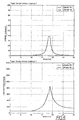
- Figures 3 - 12 show examples of principal simulations of different running modes for an energy converter such as the preferred embodiment of the invention shown in figure 1 .
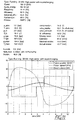
- the pistons 2, 3 and the moving part of the electrical machine 9 are accelerated by the sum of the forces produced by the cylinder pressures and the electrical machine 9. In a continuos running mode these forces are balanced (as an average) and the pistons 2, 3 are oscillating between the left and right turning points.
- the parameter section shown first for every different mode is not necessary for the understanding the principles and is not explained further.
- the energy converter produces power when the electrical machine 9 works as a generator.
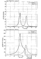
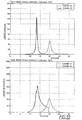
- the second diagram for each running mode shows the cylinder pressure in the two cylinders.
- the control unit 30 has controlled the operation to get ignition (in these examples for the HCCI combustion) near the turning points of the pistons.
- the third diagram for each running mode shows the cylinder (combustion) temperatures in the two cylinders.
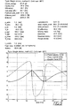
- Figure 3 shows the piston displacement, the piston velocity, and the force produced by the electrical machine in a continuous running mode.
- Figure 4 shows the cylinder pressures and the cylinder temperatures in a continuous running mode.
- Figure 10 shows the cylinder pressures and the cylinder temperatures in a single stroke mode type 2 at low temperature, cool start. Note that the valves for the second cylinder 5 are closed late in the compression stroke to make it possible achieve the very high compression needed to reach the ignition temperature.
- the first cylinder 4 is inactive (valves are open) in the stroke from the left start position to the right turning point. At the left turning point there is no combustion in the first cylinder 4 (gas spring). In the stroke from the left turning point the second cylinder 5 is inactive (valves are open).
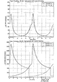
- Figure 11 shows the piston displacement, the piston velocity, and the force produced by the electrical machine in a situation involving a high power of the energy converter according to the invention and in particular, a higher charging pressure from the compressor 24.
- the diagram according to figur 11 generally corresponds to figure 3 but involves a higher speed of the two pistons 2, 3 and a higher electric power of the electric machine 9.
- Figure 12 shows the cylinder pressures and the cylinder temperatures in an operating condition according to figure 11 , i.e. involving a high power of the energy converter.
- the starting process of the combustion system described here does not require an oscillation procedure.
- the combustion system can be started within one stroke, even under cold-start conditions. Consequently, the energy converter according to the invention can give power output in a very short time.
- the very quick and simple starting and stopping procedures of the energy converter according to the invention makes it possible to run the converter in a novel way concerning start and stop.
- Previous FPE energy converters have relatively complicated starting and stopping procedures and need large energy buffers such as batteries as a back-up for the time required for the starting procedure.
- the energy converter according to the invention can use its quick starting procedure to eliminate the need for such large energy buffers.
- the converter can be operated in the intermittent mode, e.g. one-cycle operation, or even be shut off.
- the converter is used in a hybride vehicle that runs in a city where low load situations arise at traffic lights, in case of traffic jam etc.
- the engine may in such a case switch to one-cycle mode which might be close to being shut off depending on the status and capacity of the battery and how much energy is needed for lights, radio etc.
- the time period between the strokes may of course be varied.
- Another example is when the converter is used in a reserve power application.
- the invention makes it possible to obtain power as quickly as in the order of a period of net frequency (20 ms for 50 Hz) the very large back-up system of batteries/capacitors in traditional reserve power plants can be dramatically decreased. Naturally, if the invention is used in such an emergency application the capacitor should be kept fully charged during the time the converter is not in use.
- combustion principle can be selected:
- combustion mode depends on the outer requirements. Examples of such requirements are:
- combustion mode settings can be used.
- One, out of several different combustion mode settings, that exhibits the best fit to the running demands can be selected from cycle to cycle.
- both the stationary and transient output torque of the energy converter according to the invention can be optimized for minimum fuel consumption and emission levels, without need for any additional load leveling capacitor or battery.
- An energy converter according to the invention has several advantageous effects: a very high efficiency, a very low fuel consumption, it produces very small amounts of emissions and it eliminates/decreases the need for large battery stacks. The latter contributes to the efficiency, as there are energy losses associated with battery systems, and it also makes the energy converter system relatively cheap and light, as batteries generally are costly and heavy.
- the invention can be used to avoid the traditionally negative consequences of misfire in the combustion chamber. Normally, unburnt fuel leaves the engine via the exhaust pipe. By using the sensors to detect the misfire, the control unit to take adequate actions (such as keeping the valves closed) and the electric machine to aid in the following compression in the other combustion chamber, the unburnt fuel can be kept in the combustion chamber until the piston returns the next time.
- An FPE normally needs to be balanced.
- two energy converters may be arranged after each other with the rods in a line.
- Each converter may have the general design outlined in figure 1 .
- Balance can be achieved by operating the two rods totally in antiphase, controlled by communication between the control units of the converters.
- the individual phase position of the two rods can be adjusted by redistributing the effect output within one stroke with maintained conditions at the end positions of the pistons.
- Two energy converters arranged in a line may have one cylinder and thus one combustion chamber in common.
- a system comprising more than one energy converter may be arranged offset in phase so that power is delivered contineously or almost contineously from the electric machines. Such an arrangement decreases the need for capacitors.
- the energy converter may be used as an engine brake.
- a control command from e.g. the brake pedal to the control unit can be used to initiate a procedure where the combustion process is stopped and the braking energy is used to move the rod/pistons to compress only air in the cylinders. By closing and opening valves and releasing the compressed air at adequate moments the energy converter will aid in the braking process.
- the compressed air may be stored in a pressure vessel for use as a compliment to charging.
- HCCI combustion is very well suited for the energy converter according to the invention
- conventional spark ignition is on some occasions favourable and could be applied for different reasons: to start the engine at very low temperatures, to create the initial conditions for HCCI, or for example for mode transitions.
- spark ignition can also be used for longer periods in cases where this is benificial for the performance of the energy converter.
Landscapes
- Engineering & Computer Science (AREA)
- Chemical & Material Sciences (AREA)
- Combustion & Propulsion (AREA)
- Mechanical Engineering (AREA)
- General Engineering & Computer Science (AREA)
- Output Control And Ontrol Of Special Type Engine (AREA)
- Diaphragms For Electromechanical Transducers (AREA)
- Inorganic Insulating Materials (AREA)
- Particle Formation And Scattering Control In Inkjet Printers (AREA)
- Connection Of Motors, Electrical Generators, Mechanical Devices, And The Like (AREA)
Applications Claiming Priority (3)
| Application Number | Priority Date | Filing Date | Title |
|---|---|---|---|
| SE0202758A SE525796C2 (sv) | 2002-09-16 | 2002-09-16 | Energiomvandlare inrättad så att den anpassar sin uteffekt beroende på den erforderliga lasten |
| SE0202758 | 2002-09-16 | ||
| PCT/SE2003/001441 WO2004025098A1 (en) | 2002-09-16 | 2003-09-15 | Energy converter |
Publications (2)
| Publication Number | Publication Date |
|---|---|
| EP1540155A1 EP1540155A1 (en) | 2005-06-15 |
| EP1540155B1 true EP1540155B1 (en) | 2011-05-04 |
Family
ID=20289019
Family Applications (1)
| Application Number | Title | Priority Date | Filing Date |
|---|---|---|---|
| EP03795541A Expired - Lifetime EP1540155B1 (en) | 2002-09-16 | 2003-09-15 | Energy converter |
Country Status (8)
| Country | Link |
|---|---|
| US (1) | US7845317B2 (enExample) |
| EP (1) | EP1540155B1 (enExample) |
| JP (2) | JP4391942B2 (enExample) |
| AT (1) | ATE508266T1 (enExample) |
| AU (1) | AU2003263704A1 (enExample) |
| DE (1) | DE60337015D1 (enExample) |
| SE (1) | SE525796C2 (enExample) |
| WO (1) | WO2004025098A1 (enExample) |
Families Citing this family (62)
| Publication number | Priority date | Publication date | Assignee | Title |
|---|---|---|---|---|
| WO2005100769A2 (en) | 2004-04-19 | 2005-10-27 | Volvo Technology Corporation | Method and system for controlling a free-piston energy converter |
| EP1797309A4 (en) * | 2004-08-24 | 2009-12-02 | Infinia Corp | SYSTEM AND METHOD FOR MULTI-CYLINDER DOUBLE ACTION STIRLING AND THERMODYNAMIC RESONANCE FREE PISTON |
| AU2006216721B2 (en) * | 2005-02-24 | 2009-07-09 | John W. Fitzgerald | Variable stroke premixed charge compression ignition engine |
| US7290517B2 (en) | 2005-07-28 | 2007-11-06 | Caterpillar Inc. | Automatic start-up of an auxiliary power unit |
| US7291934B2 (en) | 2005-08-30 | 2007-11-06 | Caterpillar Inc. | Machine with an electrical system |
| WO2007035084A1 (en) * | 2005-09-26 | 2007-03-29 | Stichting Administratiekantoor Brinks Westmass | Free piston linear generator |
| US7240653B2 (en) | 2005-10-31 | 2007-07-10 | Caterpillar Inc | System for assisting a main engine start-up |
| US7690199B2 (en) * | 2006-01-24 | 2010-04-06 | Altor Limited Lc | System and method for electrically-coupled thermal cycle |
| DE102006029532A1 (de) * | 2006-06-20 | 2007-12-27 | Deutsches Zentrum für Luft- und Raumfahrt e.V. | Freikolbenvorrichtung und Verfahren zum Betreiben einer Freikolbenvorrichtung |
| US7484583B2 (en) | 2006-09-29 | 2009-02-03 | Caterpillar Inc. | Auxiliary power unit for moving a vehicle |
| DE102006056349A1 (de) * | 2006-11-29 | 2008-06-05 | Gerhard Schilling | Vorrichtung zur Umwandlung thermodynamischer Energie in elektrische Energie |
| JP2008223628A (ja) * | 2007-03-13 | 2008-09-25 | Mazda Motor Corp | フリーピストンエンジンの制御装置 |
| US7856714B2 (en) | 2007-10-10 | 2010-12-28 | The Invention Science Fund I, Llc | Method of retrofitting an engine |
| US7622814B2 (en) | 2007-10-04 | 2009-11-24 | Searete Llc | Electromagnetic engine |
| US7777357B2 (en) * | 2007-10-05 | 2010-08-17 | The Invention Fund I, LLC | Free piston electromagnetic engine |
| KR20100071087A (ko) | 2007-10-04 | 2010-06-28 | 시리트 엘엘씨 | 전자기 엔진 |
| US7950356B2 (en) | 2007-10-09 | 2011-05-31 | The Invention Science Fund I, Llc | Opposed piston electromagnetic engine |
| AT506084B1 (de) * | 2008-05-05 | 2009-06-15 | Man Nutzfahrzeuge Oesterreich | Antriebseinheit mit einer brennkraftmaschine und einer regelungsfrei selbstanlaufenden hubkolbenmaschine |
| DE102008053068C5 (de) * | 2008-10-24 | 2023-11-23 | TRIVIUM Business Development Company AG | Freikolbenmotor mit variablem Hub, Verfahren zum Betreiben eines Freikolbenmotors und Verwendung von Öffnungen in einer Kolbenaufnahme |
| US8261860B2 (en) | 2009-07-16 | 2012-09-11 | GM Global Technology Operations LLC | Hybrid powertrain system using free piston linear alternator engines |
| GB2476495A (en) * | 2009-12-24 | 2011-06-29 | Libertine Fpe Ltd | Free piston engine |
| WO2011091022A1 (en) | 2010-01-19 | 2011-07-28 | Altor Limited Lc | System and method for electrically-coupled heat engine and thermal cycle |
| US8549854B2 (en) | 2010-05-18 | 2013-10-08 | Achates Power, Inc. | EGR constructions for opposed-piston engines |
| GB2480461B8 (en) * | 2010-05-19 | 2012-11-14 | Univ Newcastle | Free piston internal combustion engine |
| JP5630123B2 (ja) * | 2010-07-28 | 2014-11-26 | 株式会社豊田中央研究所 | リニア発電フリーピストンエンジン、および、その始動方法 |
| US8127544B2 (en) * | 2010-11-03 | 2012-03-06 | Paul Albert Schwiesow | Two-stroke HCCI compound free-piston/gas-turbine engine |
| US8714117B2 (en) * | 2010-11-04 | 2014-05-06 | GM Global Technology Operations LLC | Free piston linear alternator utilizing opposed pistons with spring return |
| US8413617B2 (en) | 2010-11-23 | 2013-04-09 | Etagen, Inc. | High-efficiency two-piston linear combustion engine |
| US8453612B2 (en) | 2010-11-23 | 2013-06-04 | Etagen, Inc. | High-efficiency linear combustion engine |
| US8662029B2 (en) | 2010-11-23 | 2014-03-04 | Etagen, Inc. | High-efficiency linear combustion engine |
| US8677749B2 (en) * | 2011-01-28 | 2014-03-25 | EcoMotors International | Exhaust system for an internal combustion engine |
| US8997699B2 (en) | 2011-02-15 | 2015-04-07 | Etagen, Inc. | Linear free piston combustion engine with indirect work extraction via gas linkage |
| JP5724514B2 (ja) * | 2011-03-28 | 2015-05-27 | 株式会社豊田中央研究所 | フリーピストン式発電機 |
| JP5447420B2 (ja) * | 2011-03-28 | 2014-03-19 | 株式会社豊田中央研究所 | フリーピストン式発電機 |
| US20130174548A1 (en) | 2011-05-16 | 2013-07-11 | Achates Power, Inc. | EGR for a Two-Stroke Cycle Engine without a Supercharger |
| RU2493441C2 (ru) * | 2011-09-09 | 2013-09-20 | Владимир Иванович Игошин | Пневмодвигатель с электромагнитным поршнем |
| KR101283127B1 (ko) | 2011-10-18 | 2013-07-05 | 현대자동차주식회사 | 하이브리드 차량의 엔진운영방법 |
| DE102011087790B4 (de) * | 2011-12-06 | 2014-11-27 | Siemens Ag | Vorrichtung und Verfahren zur Stromerzeugung |
| US9097203B2 (en) | 2011-12-29 | 2015-08-04 | Etagen, Inc. | Methods and systems for managing a clearance gap in a piston engine |
| US20130167797A1 (en) | 2011-12-29 | 2013-07-04 | Matt Svrcek | Methods and systems for managing a clearance gap in a piston engine |
| US8720317B2 (en) | 2011-12-29 | 2014-05-13 | Etagen, Inc. | Methods and systems for managing a clearance gap in a piston engine |
| US9169797B2 (en) | 2011-12-29 | 2015-10-27 | Etagen, Inc. | Methods and systems for managing a clearance gap in a piston engine |
| US9004038B2 (en) | 2011-12-29 | 2015-04-14 | Etagen, Inc. | Methods and systems for managing a clearance gap in a piston engine |
| GB201205102D0 (en) * | 2012-03-23 | 2012-05-09 | Heatgen Ltd | Combined heat and power |
| ITTO20120368A1 (it) * | 2012-04-26 | 2012-07-26 | Edoardo Giana | Motore a pistone semilibero |
| US10215229B2 (en) | 2013-03-14 | 2019-02-26 | Etagen, Inc. | Mechanism for maintaining a clearance gap |
| US10202897B2 (en) * | 2013-04-16 | 2019-02-12 | Regents Of The University Of Minnesota | Systems and methods for transient control of a free-piston engine |
| US9366199B2 (en) * | 2014-05-09 | 2016-06-14 | Ali Farzad Farzaneh | Sliding engine with shaft on one or both ends for double or single ended combustion |
| US9719415B2 (en) | 2015-01-15 | 2017-08-01 | Etagen, Inc. | Energy storage and conversion in free-piston combustion engines |
| JP6246988B2 (ja) * | 2015-10-16 | 2017-12-13 | アムネクスト・テクノロジ株式会社 | エンジン |
| DE102016109055A1 (de) | 2016-05-17 | 2017-11-23 | Deutsches Zentrum für Luft- und Raumfahrt e.V. | Freikolbenvorrichtung und Verfahren zum Betreiben einer Freikolbenvorrichtung |
| DE102016109046A1 (de) | 2016-05-17 | 2017-11-23 | Deutsches Zentrum für Luft- und Raumfahrt e.V. | Freikolbenvorrichtung |
| DE102016109038A1 (de) | 2016-05-17 | 2017-11-23 | Deutsches Zentrum für Luft- und Raumfahrt e.V. | Freikolbenvorrichtung |
| DE102016109029A1 (de) | 2016-05-17 | 2017-11-23 | Deutsches Zentrum für Luft- und Raumfahrt e.V. | Freikolbenvorrichtung und Verfahren zum Betreiben einer Freikolbenvorrichtung |
| WO2018190156A1 (ja) * | 2017-04-13 | 2018-10-18 | アムネクスト・テクノロジ株式会社 | エンジン |
| US11168609B2 (en) * | 2017-04-24 | 2021-11-09 | General Electric Company | Adaptive linear linked piston electric power generator |
| EP3827507A1 (en) | 2018-07-24 | 2021-06-02 | Mainspring Energy, Inc. | Linear electromagnetic machine |
| US10641166B1 (en) * | 2018-12-03 | 2020-05-05 | Aquarius Engines (A.M.) Ltd. | Piston rod and free piston engine |
| CN110608094B (zh) * | 2019-09-20 | 2022-12-16 | 山东休普动力科技股份有限公司 | 一种带电动机的背置双绕组双活塞式自由活塞直线发电机 |
| CN113266464B (zh) * | 2021-06-21 | 2022-04-19 | 北京理工大学 | 一种自由活塞内燃直线发电机运行系统及运行控制方法 |
| US11698022B1 (en) | 2022-05-18 | 2023-07-11 | Cyclazoom, LLC | Modified cycle two-stroke engine |
| US11519324B1 (en) | 2022-05-18 | 2022-12-06 | Cyclazoom, LLC | Four-stroke engine with two-stage exhaust cycle |
Family Cites Families (26)
| Publication number | Priority date | Publication date | Assignee | Title |
|---|---|---|---|---|
| US1903361A (en) * | 1928-08-29 | 1933-04-04 | Claude L Post | Feeding device |
| US1903381A (en) * | 1932-09-23 | 1933-04-04 | Harry E Kennedy | Internal combustion engine |
| US3612895A (en) * | 1969-08-11 | 1971-10-12 | Nasa | Pulse coupling circuit |
| US3612892A (en) * | 1970-07-30 | 1971-10-12 | Textron Inc | Motor generator with automatic speed and idling control |
| US3986796A (en) * | 1972-07-06 | 1976-10-19 | Moiroux Auguste F | Direct action compressor fitted with a one-piece piston |
| US3805083A (en) * | 1973-04-13 | 1974-04-16 | M Demetrescu | Vibrating-to-rotary energy converter |
| DE3139357C2 (de) * | 1981-10-02 | 1984-02-02 | Zuv "Progress", Sofija | Verfahren für die Stromerzeugung bei einem zyklischen Verbrennungsprozeß |
| JPS643235A (en) * | 1987-06-24 | 1989-01-09 | Aisin Seiki | Free piston engine |
| DE3727335A1 (de) * | 1987-08-17 | 1988-02-25 | Gerold Ing Grad Bieber | Viertakt-brennkraftmaschine mit abgasnutzung |
| DE3843207A1 (de) * | 1988-12-22 | 1990-06-07 | Hinger Klaus Juergen Prof Dr I | Verbrennungsmotor |
| US5893343A (en) | 1994-06-09 | 1999-04-13 | Rigazzi; Pier Andrea | Linear electrical energy generator |
| US5788003A (en) * | 1996-01-29 | 1998-08-04 | Spiers; Kent | Electrically powered motor vehicle with linear electric generator |
| IT1283369B1 (it) * | 1996-07-30 | 1998-04-17 | Rinaldo Lampis | Gruppo elettrogeno lineare ad alto rendimento,metodo di controllo e gruppo di trazione con esso |
| US5775273A (en) | 1997-07-01 | 1998-07-07 | Sunpower, Inc. | Free piston internal combustion engine |
| JPH11336646A (ja) * | 1998-05-25 | 1999-12-07 | Honda Motor Co Ltd | ハイブリッド車の内燃機関の始動判別装置 |
| US6199519B1 (en) * | 1998-06-25 | 2001-03-13 | Sandia Corporation | Free-piston engine |
| JP4056633B2 (ja) | 1998-08-04 | 2008-03-05 | 日産自動車株式会社 | 内燃機関のトルク制御装置 |
| RU2150014C1 (ru) * | 1999-03-16 | 2000-05-27 | Пинский Феликс Ильич | Свободнопоршневой двигатель внутреннего сгорания с линейным электрическим генератором переменного тока |
| JP2000316299A (ja) * | 1999-04-27 | 2000-11-14 | Mitsuba Corp | 始動発電機 |
| DE19943993A1 (de) * | 1999-09-14 | 2001-03-15 | Volkswagen Ag | Brennkraftmaschine |
| US6825575B1 (en) * | 1999-09-28 | 2004-11-30 | Borealis Technical Limited | Electronically controlled engine generator set |
| JP3903476B2 (ja) * | 1999-09-30 | 2007-04-11 | マツダ株式会社 | 車両の制御装置 |
| JP2001241302A (ja) | 2000-02-29 | 2001-09-07 | Mitsubishi Heavy Ind Ltd | フリーピストンエンジン駆動リニア発電装置 |
| JP3515039B2 (ja) * | 2000-03-03 | 2004-04-05 | 沖電気工業株式会社 | テキスト音声変換装置におけるピッチパタン制御方法 |
| US6541875B1 (en) * | 2000-05-17 | 2003-04-01 | Caterpillar Inc | Free piston engine with electrical power output |
| JP4450213B2 (ja) * | 2004-11-12 | 2010-04-14 | 国産電機株式会社 | 燃料噴射装置用電源装置 |
-
2002
- 2002-09-16 SE SE0202758A patent/SE525796C2/sv not_active IP Right Cessation
-
2003
- 2003-09-15 EP EP03795541A patent/EP1540155B1/en not_active Expired - Lifetime
- 2003-09-15 AT AT03795541T patent/ATE508266T1/de not_active IP Right Cessation
- 2003-09-15 DE DE60337015T patent/DE60337015D1/de not_active Expired - Lifetime
- 2003-09-15 AU AU2003263704A patent/AU2003263704A1/en not_active Abandoned
- 2003-09-15 JP JP2004535339A patent/JP4391942B2/ja not_active Expired - Fee Related
- 2003-09-15 WO PCT/SE2003/001441 patent/WO2004025098A1/en not_active Ceased
-
2005
- 2005-03-16 US US10/907,026 patent/US7845317B2/en not_active Expired - Fee Related
-
2009
- 2009-05-13 JP JP2009116791A patent/JP4995229B2/ja not_active Expired - Fee Related
Also Published As
| Publication number | Publication date |
|---|---|
| SE0202758L (sv) | 2004-03-17 |
| AU2003263704A1 (en) | 2004-04-30 |
| AU2003263704A8 (en) | 2004-04-30 |
| JP2005539170A (ja) | 2005-12-22 |
| WO2004025098A1 (en) | 2004-03-25 |
| JP2009216100A (ja) | 2009-09-24 |
| EP1540155A1 (en) | 2005-06-15 |
| JP4391942B2 (ja) | 2009-12-24 |
| ATE508266T1 (de) | 2011-05-15 |
| US20080036312A1 (en) | 2008-02-14 |
| SE525796C2 (sv) | 2005-04-26 |
| DE60337015D1 (de) | 2011-06-16 |
| SE0202758D0 (sv) | 2002-09-16 |
| JP4995229B2 (ja) | 2012-08-08 |
| US7845317B2 (en) | 2010-12-07 |
Similar Documents
| Publication | Publication Date | Title |
|---|---|---|
| EP1540155B1 (en) | Energy converter | |
| US11255260B2 (en) | Variable compression ratio engines and methods for HCCI compression ignition operation | |
| US6223846B1 (en) | Vehicle operating method and system | |
| US7231998B1 (en) | Operating a vehicle with braking energy recovery | |
| CN101506492B (zh) | 带再生器的6冲程内燃机 | |
| CN101424212B (zh) | 包括旋转分离的进气压缩机和排气涡轮的内燃机压缩系统 | |
| US5992390A (en) | Fuel efficient hybrid internal combustion engine | |
| US6568186B2 (en) | Hybrid expansible chamber engine with internal combustion and pneumatic modes | |
| US7607503B1 (en) | Operating a vehicle with high fuel efficiency | |
| EP1133626B1 (en) | Method of controlling the process of combustion in an internal combustion engine, and engine with means for varying the effective compression ratio of the cylinders | |
| JP2013507578A (ja) | 油圧式内燃機関 | |
| US20070150164A1 (en) | Variable compression ratio internal combustion engine | |
| WO2010044873A1 (en) | External compression two-stroke internal combustion engine with burner manifold | |
| Trajkovic et al. | Investigation of different valve geometries and valve timing strategies and their effect on regenerative efficiency for a pneumatic hybrid with variable valve actuation | |
| Higelin et al. | Parametric optimization of a new hybrid pneumatic-combustion engine concept | |
| CN110087929B (zh) | 用于运行驱动系统的方法、驱动系统和机动车 | |
| RU2117788C1 (ru) | Способ работы силовой установки машины, способ регулирования работы силовой установки машины и силовая установка машины | |
| WO2006051299A1 (en) | A pressure-charged gasoline internal combustion engine | |
| EP1423589B1 (en) | A method of torque modulation | |
| RU2112665C1 (ru) | Способ передачи энергии колесам автомобиля и силовая установка для осуществления способа | |
| US20190301379A1 (en) | Engine configuration for performing compression and expansion in a single cylinder | |
| Hirose et al. | The high-expansion-ratio gasoline engine for the hybrid passenger car | |
| Xu et al. | Hierarchical hybrid control of a four-stroke free-piston engine for electrical power generation | |
| Li et al. | Modeling of a two-stroke free-piston engine with hcci combustion | |
| RU2825688C2 (ru) | Четырехтактный цилиндр относительного движения со специальной камерой сжатия |
Legal Events
| Date | Code | Title | Description |
|---|---|---|---|
| PUAI | Public reference made under article 153(3) epc to a published international application that has entered the european phase |
Free format text: ORIGINAL CODE: 0009012 |
|
| 17P | Request for examination filed |
Effective date: 20050321 |
|
| AK | Designated contracting states |
Kind code of ref document: A1 Designated state(s): AT BE BG CH CY CZ DE DK EE ES FI FR GB GR HU IE IT LI LU MC NL PT RO SE SI SK TR |
|
| AX | Request for extension of the european patent |
Extension state: AL LT LV MK |
|
| RIN1 | Information on inventor provided before grant (corrected) |
Inventor name: WIRMARK, GOERAN Inventor name: HOEGLUND, ANDERS Inventor name: SOMHURST, JOOP Inventor name: DENBRATT, INGEMAR Inventor name: LUNDGREN, STAFFAN Inventor name: MAX, ERLAND Inventor name: GERTMAR, LARS |
|
| DAX | Request for extension of the european patent (deleted) | ||
| 17Q | First examination report despatched |
Effective date: 20080725 |
|
| GRAP | Despatch of communication of intention to grant a patent |
Free format text: ORIGINAL CODE: EPIDOSNIGR1 |
|
| GRAS | Grant fee paid |
Free format text: ORIGINAL CODE: EPIDOSNIGR3 |
|
| GRAA | (expected) grant |
Free format text: ORIGINAL CODE: 0009210 |
|
| AK | Designated contracting states |
Kind code of ref document: B1 Designated state(s): AT BE BG CH CY CZ DE DK EE ES FI FR GB GR HU IE IT LI LU MC NL PT RO SE SI SK TR |
|
| REG | Reference to a national code |
Ref country code: GB Ref legal event code: FG4D |
|
| REG | Reference to a national code |
Ref country code: CH Ref legal event code: EP |
|
| REG | Reference to a national code |
Ref country code: IE Ref legal event code: FG4D |
|
| REF | Corresponds to: |
Ref document number: 60337015 Country of ref document: DE Date of ref document: 20110616 Kind code of ref document: P |
|
| REG | Reference to a national code |
Ref country code: DE Ref legal event code: R096 Ref document number: 60337015 Country of ref document: DE Effective date: 20110616 |
|
| REG | Reference to a national code |
Ref country code: NL Ref legal event code: T3 |
|
| REG | Reference to a national code |
Ref country code: SE Ref legal event code: TRGR |
|
| RAP2 | Party data changed (patent owner data changed or rights of a patent transferred) |
Owner name: VOLVO CAR CORPORATION Owner name: VOLVO TECHNOLOGY CORPORATION |
|
| PG25 | Lapsed in a contracting state [announced via postgrant information from national office to epo] |
Ref country code: PT Free format text: LAPSE BECAUSE OF FAILURE TO SUBMIT A TRANSLATION OF THE DESCRIPTION OR TO PAY THE FEE WITHIN THE PRESCRIBED TIME-LIMIT Effective date: 20110905 |
|
| PG25 | Lapsed in a contracting state [announced via postgrant information from national office to epo] |
Ref country code: SI Free format text: LAPSE BECAUSE OF FAILURE TO SUBMIT A TRANSLATION OF THE DESCRIPTION OR TO PAY THE FEE WITHIN THE PRESCRIBED TIME-LIMIT Effective date: 20110504 Ref country code: FI Free format text: LAPSE BECAUSE OF FAILURE TO SUBMIT A TRANSLATION OF THE DESCRIPTION OR TO PAY THE FEE WITHIN THE PRESCRIBED TIME-LIMIT Effective date: 20110504 Ref country code: BE Free format text: LAPSE BECAUSE OF FAILURE TO SUBMIT A TRANSLATION OF THE DESCRIPTION OR TO PAY THE FEE WITHIN THE PRESCRIBED TIME-LIMIT Effective date: 20110504 Ref country code: AT Free format text: LAPSE BECAUSE OF FAILURE TO SUBMIT A TRANSLATION OF THE DESCRIPTION OR TO PAY THE FEE WITHIN THE PRESCRIBED TIME-LIMIT Effective date: 20110504 Ref country code: CY Free format text: LAPSE BECAUSE OF FAILURE TO SUBMIT A TRANSLATION OF THE DESCRIPTION OR TO PAY THE FEE WITHIN THE PRESCRIBED TIME-LIMIT Effective date: 20110504 Ref country code: ES Free format text: LAPSE BECAUSE OF FAILURE TO SUBMIT A TRANSLATION OF THE DESCRIPTION OR TO PAY THE FEE WITHIN THE PRESCRIBED TIME-LIMIT Effective date: 20110815 Ref country code: GR Free format text: LAPSE BECAUSE OF FAILURE TO SUBMIT A TRANSLATION OF THE DESCRIPTION OR TO PAY THE FEE WITHIN THE PRESCRIBED TIME-LIMIT Effective date: 20110805 |
|
| PG25 | Lapsed in a contracting state [announced via postgrant information from national office to epo] |
Ref country code: CZ Free format text: LAPSE BECAUSE OF FAILURE TO SUBMIT A TRANSLATION OF THE DESCRIPTION OR TO PAY THE FEE WITHIN THE PRESCRIBED TIME-LIMIT Effective date: 20110504 Ref country code: EE Free format text: LAPSE BECAUSE OF FAILURE TO SUBMIT A TRANSLATION OF THE DESCRIPTION OR TO PAY THE FEE WITHIN THE PRESCRIBED TIME-LIMIT Effective date: 20110504 |
|
| PG25 | Lapsed in a contracting state [announced via postgrant information from national office to epo] |
Ref country code: RO Free format text: LAPSE BECAUSE OF FAILURE TO SUBMIT A TRANSLATION OF THE DESCRIPTION OR TO PAY THE FEE WITHIN THE PRESCRIBED TIME-LIMIT Effective date: 20110504 Ref country code: SK Free format text: LAPSE BECAUSE OF FAILURE TO SUBMIT A TRANSLATION OF THE DESCRIPTION OR TO PAY THE FEE WITHIN THE PRESCRIBED TIME-LIMIT Effective date: 20110504 Ref country code: DK Free format text: LAPSE BECAUSE OF FAILURE TO SUBMIT A TRANSLATION OF THE DESCRIPTION OR TO PAY THE FEE WITHIN THE PRESCRIBED TIME-LIMIT Effective date: 20110504 |
|
| PLBE | No opposition filed within time limit |
Free format text: ORIGINAL CODE: 0009261 |
|
| STAA | Information on the status of an ep patent application or granted ep patent |
Free format text: STATUS: NO OPPOSITION FILED WITHIN TIME LIMIT |
|
| 26N | No opposition filed |
Effective date: 20120207 |
|
| PG25 | Lapsed in a contracting state [announced via postgrant information from national office to epo] |
Ref country code: MC Free format text: LAPSE BECAUSE OF NON-PAYMENT OF DUE FEES Effective date: 20110930 |
|
| REG | Reference to a national code |
Ref country code: CH Ref legal event code: PL |
|
| REG | Reference to a national code |
Ref country code: DE Ref legal event code: R097 Ref document number: 60337015 Country of ref document: DE Effective date: 20120207 |
|
| REG | Reference to a national code |
Ref country code: IE Ref legal event code: MM4A |
|
| PG25 | Lapsed in a contracting state [announced via postgrant information from national office to epo] |
Ref country code: LI Free format text: LAPSE BECAUSE OF NON-PAYMENT OF DUE FEES Effective date: 20110930 Ref country code: IE Free format text: LAPSE BECAUSE OF NON-PAYMENT OF DUE FEES Effective date: 20110915 Ref country code: CH Free format text: LAPSE BECAUSE OF NON-PAYMENT OF DUE FEES Effective date: 20110930 |
|
| PG25 | Lapsed in a contracting state [announced via postgrant information from national office to epo] |
Ref country code: LU Free format text: LAPSE BECAUSE OF NON-PAYMENT OF DUE FEES Effective date: 20110915 |
|
| PG25 | Lapsed in a contracting state [announced via postgrant information from national office to epo] |
Ref country code: BG Free format text: LAPSE BECAUSE OF FAILURE TO SUBMIT A TRANSLATION OF THE DESCRIPTION OR TO PAY THE FEE WITHIN THE PRESCRIBED TIME-LIMIT Effective date: 20110804 |
|
| PG25 | Lapsed in a contracting state [announced via postgrant information from national office to epo] |
Ref country code: TR Free format text: LAPSE BECAUSE OF FAILURE TO SUBMIT A TRANSLATION OF THE DESCRIPTION OR TO PAY THE FEE WITHIN THE PRESCRIBED TIME-LIMIT Effective date: 20110504 |
|
| PG25 | Lapsed in a contracting state [announced via postgrant information from national office to epo] |
Ref country code: HU Free format text: LAPSE BECAUSE OF FAILURE TO SUBMIT A TRANSLATION OF THE DESCRIPTION OR TO PAY THE FEE WITHIN THE PRESCRIBED TIME-LIMIT Effective date: 20110504 |
|
| REG | Reference to a national code |
Ref country code: FR Ref legal event code: PLFP Year of fee payment: 14 |
|
| PGFP | Annual fee paid to national office [announced via postgrant information from national office to epo] |
Ref country code: GB Payment date: 20160923 Year of fee payment: 14 Ref country code: NL Payment date: 20160920 Year of fee payment: 14 Ref country code: IT Payment date: 20160921 Year of fee payment: 14 Ref country code: DE Payment date: 20160922 Year of fee payment: 14 |
|
| PGFP | Annual fee paid to national office [announced via postgrant information from national office to epo] |
Ref country code: SE Payment date: 20160923 Year of fee payment: 14 Ref country code: FR Payment date: 20160908 Year of fee payment: 14 |
|
| REG | Reference to a national code |
Ref country code: DE Ref legal event code: R119 Ref document number: 60337015 Country of ref document: DE |
|
| REG | Reference to a national code |
Ref country code: SE Ref legal event code: EUG |
|
| REG | Reference to a national code |
Ref country code: NL Ref legal event code: MM Effective date: 20171001 |
|
| GBPC | Gb: european patent ceased through non-payment of renewal fee |
Effective date: 20170915 |
|
| PG25 | Lapsed in a contracting state [announced via postgrant information from national office to epo] |
Ref country code: NL Free format text: LAPSE BECAUSE OF NON-PAYMENT OF DUE FEES Effective date: 20171001 |
|
| REG | Reference to a national code |
Ref country code: FR Ref legal event code: ST Effective date: 20180531 |
|
| PG25 | Lapsed in a contracting state [announced via postgrant information from national office to epo] |
Ref country code: GB Free format text: LAPSE BECAUSE OF NON-PAYMENT OF DUE FEES Effective date: 20170915 Ref country code: DE Free format text: LAPSE BECAUSE OF NON-PAYMENT OF DUE FEES Effective date: 20180404 |
|
| PG25 | Lapsed in a contracting state [announced via postgrant information from national office to epo] |
Ref country code: IT Free format text: LAPSE BECAUSE OF NON-PAYMENT OF DUE FEES Effective date: 20170915 Ref country code: FR Free format text: LAPSE BECAUSE OF NON-PAYMENT OF DUE FEES Effective date: 20171002 |
|
| PG25 | Lapsed in a contracting state [announced via postgrant information from national office to epo] |
Ref country code: SE Free format text: LAPSE BECAUSE OF NON-PAYMENT OF DUE FEES Effective date: 20170916 |