WO2018190156A1 - エンジン - Google Patents
エンジン Download PDFInfo
- Publication number
- WO2018190156A1 WO2018190156A1 PCT/JP2018/013737 JP2018013737W WO2018190156A1 WO 2018190156 A1 WO2018190156 A1 WO 2018190156A1 JP 2018013737 W JP2018013737 W JP 2018013737W WO 2018190156 A1 WO2018190156 A1 WO 2018190156A1
- Authority
- WO
- WIPO (PCT)
- Prior art keywords
- piston
- gas
- combustion
- engine
- combustion chamber
- Prior art date
Links
Images


Classifications
-
- F—MECHANICAL ENGINEERING; LIGHTING; HEATING; WEAPONS; BLASTING
- F02—COMBUSTION ENGINES; HOT-GAS OR COMBUSTION-PRODUCT ENGINE PLANTS
- F02B—INTERNAL-COMBUSTION PISTON ENGINES; COMBUSTION ENGINES IN GENERAL
- F02B71/00—Free-piston engines; Engines without rotary main shaft
- F02B71/04—Adaptations of such engines for special use; Combinations of such engines with apparatus driven thereby
-
- F—MECHANICAL ENGINEERING; LIGHTING; HEATING; WEAPONS; BLASTING
- F01—MACHINES OR ENGINES IN GENERAL; ENGINE PLANTS IN GENERAL; STEAM ENGINES
- F01B—MACHINES OR ENGINES, IN GENERAL OR OF POSITIVE-DISPLACEMENT TYPE, e.g. STEAM ENGINES
- F01B11/00—Reciprocating-piston machines or engines without rotary main shaft, e.g. of free-piston type
- F01B11/001—Reciprocating-piston machines or engines without rotary main shaft, e.g. of free-piston type in which the movement in the two directions is obtained by one double acting piston motor
- F01B11/002—Reciprocating-piston machines or engines without rotary main shaft, e.g. of free-piston type in which the movement in the two directions is obtained by one double acting piston motor one side of the double acting piston motor being always under the influence of the fluid under pressure
-
- F—MECHANICAL ENGINEERING; LIGHTING; HEATING; WEAPONS; BLASTING
- F01—MACHINES OR ENGINES IN GENERAL; ENGINE PLANTS IN GENERAL; STEAM ENGINES
- F01D—NON-POSITIVE DISPLACEMENT MACHINES OR ENGINES, e.g. STEAM TURBINES
- F01D13/00—Combinations of two or more machines or engines
- F01D13/02—Working-fluid interconnection of machines or engines
-
- F—MECHANICAL ENGINEERING; LIGHTING; HEATING; WEAPONS; BLASTING
- F01—MACHINES OR ENGINES IN GENERAL; ENGINE PLANTS IN GENERAL; STEAM ENGINES
- F01K—STEAM ENGINE PLANTS; STEAM ACCUMULATORS; ENGINE PLANTS NOT OTHERWISE PROVIDED FOR; ENGINES USING SPECIAL WORKING FLUIDS OR CYCLES
- F01K23/00—Plants characterised by more than one engine delivering power external to the plant, the engines being driven by different fluids
- F01K23/02—Plants characterised by more than one engine delivering power external to the plant, the engines being driven by different fluids the engine cycles being thermally coupled
-
- F—MECHANICAL ENGINEERING; LIGHTING; HEATING; WEAPONS; BLASTING
- F02—COMBUSTION ENGINES; HOT-GAS OR COMBUSTION-PRODUCT ENGINE PLANTS
- F02B—INTERNAL-COMBUSTION PISTON ENGINES; COMBUSTION ENGINES IN GENERAL
- F02B71/00—Free-piston engines; Engines without rotary main shaft
- F02B71/04—Adaptations of such engines for special use; Combinations of such engines with apparatus driven thereby
- F02B71/06—Free-piston combustion gas generators per se
-
- F—MECHANICAL ENGINEERING; LIGHTING; HEATING; WEAPONS; BLASTING
- F02—COMBUSTION ENGINES; HOT-GAS OR COMBUSTION-PRODUCT ENGINE PLANTS
- F02C—GAS-TURBINE PLANTS; AIR INTAKES FOR JET-PROPULSION PLANTS; CONTROLLING FUEL SUPPLY IN AIR-BREATHING JET-PROPULSION PLANTS
- F02C5/00—Gas-turbine plants characterised by the working fluid being generated by intermittent combustion
- F02C5/02—Gas-turbine plants characterised by the working fluid being generated by intermittent combustion characterised by the arrangement of the combustion chamber in the chamber in the plant
-
- F—MECHANICAL ENGINEERING; LIGHTING; HEATING; WEAPONS; BLASTING
- F02—COMBUSTION ENGINES; HOT-GAS OR COMBUSTION-PRODUCT ENGINE PLANTS
- F02C—GAS-TURBINE PLANTS; AIR INTAKES FOR JET-PROPULSION PLANTS; CONTROLLING FUEL SUPPLY IN AIR-BREATHING JET-PROPULSION PLANTS
- F02C5/00—Gas-turbine plants characterised by the working fluid being generated by intermittent combustion
- F02C5/06—Gas-turbine plants characterised by the working fluid being generated by intermittent combustion the working fluid being generated in an internal-combustion gas generated of the positive-displacement type having essentially no mechanical power output
- F02C5/08—Gas-turbine plants characterised by the working fluid being generated by intermittent combustion the working fluid being generated in an internal-combustion gas generated of the positive-displacement type having essentially no mechanical power output the gas generator being of the free-piston type
-
- F—MECHANICAL ENGINEERING; LIGHTING; HEATING; WEAPONS; BLASTING
- F02—COMBUSTION ENGINES; HOT-GAS OR COMBUSTION-PRODUCT ENGINE PLANTS
- F02C—GAS-TURBINE PLANTS; AIR INTAKES FOR JET-PROPULSION PLANTS; CONTROLLING FUEL SUPPLY IN AIR-BREATHING JET-PROPULSION PLANTS
- F02C5/00—Gas-turbine plants characterised by the working fluid being generated by intermittent combustion
- F02C5/12—Gas-turbine plants characterised by the working fluid being generated by intermittent combustion the combustion chambers having inlet or outlet valves, e.g. Holzwarth gas-turbine plants
-
- H—ELECTRICITY
- H02—GENERATION; CONVERSION OR DISTRIBUTION OF ELECTRIC POWER
- H02K—DYNAMO-ELECTRIC MACHINES
- H02K35/00—Generators with reciprocating, oscillating or vibrating coil system, magnet, armature or other part of the magnetic circuit
- H02K35/02—Generators with reciprocating, oscillating or vibrating coil system, magnet, armature or other part of the magnetic circuit with moving magnets and stationary coil systems
-
- F—MECHANICAL ENGINEERING; LIGHTING; HEATING; WEAPONS; BLASTING
- F02—COMBUSTION ENGINES; HOT-GAS OR COMBUSTION-PRODUCT ENGINE PLANTS
- F02B—INTERNAL-COMBUSTION PISTON ENGINES; COMBUSTION ENGINES IN GENERAL
- F02B75/00—Other engines
- F02B75/02—Engines characterised by their cycles, e.g. six-stroke
- F02B2075/022—Engines characterised by their cycles, e.g. six-stroke having less than six strokes per cycle
- F02B2075/025—Engines characterised by their cycles, e.g. six-stroke having less than six strokes per cycle two
-
- F—MECHANICAL ENGINEERING; LIGHTING; HEATING; WEAPONS; BLASTING
- F02—COMBUSTION ENGINES; HOT-GAS OR COMBUSTION-PRODUCT ENGINE PLANTS
- F02B—INTERNAL-COMBUSTION PISTON ENGINES; COMBUSTION ENGINES IN GENERAL
- F02B63/00—Adaptations of engines for driving pumps, hand-held tools or electric generators; Portable combinations of engines with engine-driven devices
- F02B63/04—Adaptations of engines for driving pumps, hand-held tools or electric generators; Portable combinations of engines with engine-driven devices for electric generators
- F02B63/041—Linear electric generators
-
- H—ELECTRICITY
- H02—GENERATION; CONVERSION OR DISTRIBUTION OF ELECTRIC POWER
- H02K—DYNAMO-ELECTRIC MACHINES
- H02K7/00—Arrangements for handling mechanical energy structurally associated with dynamo-electric machines, e.g. structural association with mechanical driving motors or auxiliary dynamo-electric machines
- H02K7/18—Structural association of electric generators with mechanical driving motors, e.g. with turbines
- H02K7/1869—Linear generators; sectional generators
- H02K7/1876—Linear generators; sectional generators with reciprocating, linearly oscillating or vibrating parts
- H02K7/1884—Linear generators; sectional generators with reciprocating, linearly oscillating or vibrating parts structurally associated with free piston engines
Definitions
- the present invention relates to an engine that uses high-pressure combustion gas generated in a combustion chamber as power.
- the engine includes a combustion chamber, a fuel supply path for supplying fuel and air mixed with the combustion chamber, an igniter for igniting a mixed gas in the combustion chamber, and a gas for ejecting the combustion gas from the combustion chamber through a nozzle.
- the gas discharge path can be opened by the switching device immediately before ignition, simultaneously with ignition, or immediately after ignition.
- One embodiment of the present invention is an engine having a gas supply unit that supplies combustion gas for driving in accordance with a reciprocating linear motion of a piston.
- the gas supply unit includes a first combustion chamber provided on the first side of the piston, a first gas output port for supplying high-pressure combustion gas generated in the first combustion chamber for driving, and a piston And a second chamber that generates a second force on the opposite side that moves the piston to the first side.
- the engine further includes a piston control unit that controls the position of the piston against the first force and the second force of the piston that is moved by the combustion in the first combustion chamber.
- the gas in the combustion chamber may be a mixed gas of fuel and air, or may be ignited by an igniter or the like when compressed. Further, the gas in the combustion chamber may be air, or fuel may be injected and compression ignition may be performed.
- the gas supply unit may include an exhaust port for exhausting low-pressure combustion gas in the first combustion chamber.
- the replacement efficiency between the combustion gas and the mixed gas or air in the first combustion chamber can be improved.
- the second force may be a force (rebound) generated by a spring or magnetism.
- a typical second chamber is a second combustion chamber, and the gas supply unit supplies a second gas output for driving the high-pressure combustion gas generated in the second combustion chamber. It may include a mouth.
- the high-pressure combustion gas can be alternately supplied from the first and second combustion chambers for driving, and the driving combustion gas can be supplied from the gas supply unit in one cycle unit of the movement of the piston.
- the piston control unit may directly control the position of the piston mechanically or magnetically.
- the piston control unit may be provided outside the first combustion chamber and the second chamber, and may include a first control unit that controls the position of the piston via a shaft connected to the piston.
- the engine may have a first linear power generation unit connected via a piston and a shaft.
- the first linear power generation unit may include a function as the first control unit.
- the first linear power generation unit may include a function as a first linear motor that drives the piston to start the engine. Since the piston control unit controls the position of the piston against the first force of the piston or the second force acting on the opposite side, the power and / or the opposite is required for controlling the position of the piston by the linear power generation unit. The power that opposes the power acting on the side can be regenerated as electrical energy.
- the piston control unit may include a second control unit that is disposed on the outer periphery of the first combustion chamber and the second chamber (sub chamber) and controls the position of the piston via a magnetic field.
- the engine may include a second linear power generation unit that is disposed on the outer periphery of the first combustion chamber and the second chamber and connected to the piston via a magnetic field.
- the second linear power generation unit may include a function as a second control unit.
- the second linear power generation unit may include a function as a second linear motor that drives the piston to start the engine.
- the engine may have a gas turbine unit (gas turbine) to which high-pressure combustion gas is supplied from the first gas output port.
- a typical gas turbine unit includes a radial turbine, and a plurality of gas supply units may be disposed along the periphery of the radial turbine.
- One embodiment of the present invention is a power generation apparatus having the above-described engine and a generator connected to a gas turbine unit.
- the gas turbine and the generator may be directly connected or may be connected via a gear or the like.
- the figure which shows schematic structure of an electric power generation unit The figure which shows schematic structure of an engine.
- the figure which shows schematic structure of a different engine Furthermore, the figure which shows schematic structure of a different engine. Furthermore, the figure which shows schematic structure of a different engine. Furthermore, the figure which shows schematic structure of a different engine. Furthermore, the figure which shows schematic structure of a different engine. Furthermore, the figure which shows schematic structure of a different engine. Furthermore, the figure which shows schematic structure of a different engine. Furthermore, the figure which shows schematic structure of a different engine. Furthermore, the figure which shows schematic structure of a different engine. Furthermore, the figure which shows schematic structure of a different engine. The figure explaining the timing of supply of driving gas.
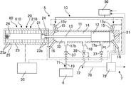
- a power generator including an engine 5 including a plurality of gas supply units 10 and a gas turbine unit 6, and a generator 3 that is rotationally driven by a gas turbine unit (for example, a radial turbine, hereinafter referred to as a turbine) 6.
- Power generation unit) 1 is shown.
- the power generation unit 1 includes a generator 3 linearly connected to the turbine 6 in the longitudinal direction, a plurality of gas supply units 10 arranged around the turbine 6 and the turbine exhaust nozzle 7, and a gas supply unit. 10 and the linear power generation unit 20 provided one-on-one.
- Each linear power generation unit 20 is connected to the length of the gas supply unit 10 and also functions as a piston control unit 60.
- the turbine 6, the generator 3, the plurality of gas supply units 10, and the linear power generation unit 20 are provided in a state where the entirety can be installed or transported as one apparatus.
- the power generation unit 1 includes a linear power generation unit (linear motor unit) 20 that also serves as the piston control unit 60 and a management unit 50 that controls the power generation unit 1 via the gas supply unit 10 and a gas supply unit 10 for combustion.
- a fuel supply unit 80 for supplying the fuel and air.
- the gas turbine unit 6 may be a radial turbine (radial flow turbine), an axial flow turbine, or a combination of a radial turbine and an axial flow turbine.
- a plurality of, for example, four gas supply units 10 are arranged at symmetrical positions around the turbine 6, for example, at a pitch of 90 degrees, and the combustion gas for driving is turbined at different timings or synchronously. 6 is supplied.
- the number of gas supply units 10 is not limited to four, may be three or less, may be five or more, and the arrangement is not limited to a 90-degree pitch.
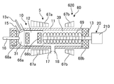
- FIG. 2 shows a configuration of a gas supply unit 10 that supplies a high-pressure combustion gas 71 for driving to the turbine 6 and a linear power generation unit 20 that also serves as a piston control unit 60 that controls the piston 12 of the gas supply unit 10.
- the gas supply unit 10 includes a cylinder 11 in which a piston 12 performs a reciprocating linear motion within an interior 14, and a first combustion chamber 31 on one side (first side, right side in the figure) of the piston 12 in the cylinder 11. And the second combustion chamber 32 is formed on the other side (second side, left side in the figure) of the piston 12.
- the linear power generation unit 20 that also serves as the piston control unit 60 is connected so as to be integrated in the longitudinal direction of the gas supply unit 10.
- the linear power generation unit 20 is provided adjacent to the left side of the gas supply unit 10.
- the linear power generation unit 20 has a cylindrical housing 25 and a plurality of fixed members arranged in the longitudinal direction (axial direction) inside the housing 25 so as to function as a power generation coil during power generation and as a fixed electromagnet when driving a motor. It includes a coil (electromagnet) 23 and a movable magnet (movable electromagnet) 21 that moves along the axial direction inside the fixed coil 23, and the movable magnet 21 is connected by a piston 12 and a shaft (rod) 13.
- Coil springs 24 that function as shock absorbers that relieve the movement of the movable magnet 21 at the end are provided at both ends inside the housing 25.
- the magnetic poles of the electromagnetic coils 23a at both ends may be set opposite to the movable magnet 21 so as to alleviate or absorb the movement or impact at both ends of the piston 12.
- the movable magnet 21 may be a permanent magnet
- the fixed coils (electromagnets) 23a at both ends may be permanent magnets having magnetic poles that repel the movable magnet 21.
- the fixed coil 23 may not be all electromagnets, and a magnet at a position suitable for controlling the piston 12 may be replaced with a permanent magnet having an appropriate magnetic pole.
- the piston control unit 60 is disposed outside the first combustion chamber 31 and the second combustion chamber 32 and controls the position of the piston 12 via the shaft 13 connected to the piston 12.
- a first control unit 610 is included.
- the linear power generation unit 20 includes a first linear power generation unit 210 connected to the piston 12 via the shaft 13. Further, the first linear power generation unit 210 includes a function as the first control unit 610, and the first linear power generation unit 210 drives the piston 12 to control the engine 5, specifically, each gas supply unit 10.
- a function as a first linear motor to be started is included. Further, in this engine 5, the first combustion chamber 31 and the second combustion chamber 32 mutually act on the force (second force) acting on the opposite side to the force (first force) generated in the piston 12 by combustion. Function as a second chamber (sub-chamber).
- the gas supply unit 10 introduces air from the fuel supply unit 80 or a mixture of air and fuel near the first end (right end) and the second end (left end) of the interior 14 of the cylinder 11. It includes a port 15, an intake valve 15 v that opens and closes the intake port 15, and a fuel injection device 16.
- the fuel injection device 16 also serves as an ignition device. When the temperature of the compressed air in the combustion chambers 31 and 32 can be increased to the ignition temperature of the fuel by the movement amount of the piston 12, the fuel is injected from the fuel injection device 16 to burn in the combustion chambers 31 and 32. Can be started (compression ignition mode).
- the fuel supply unit 80 supplies mixed air with fuel to the combustion chambers 31 and 32 instead of the compressed air, and the fuel injection device 16 can function as an ignition device to start combustion in the combustion chambers 31 and 32 (spark ignition mode).
- spark ignition mode combustion technology related to premixed compression automatic ignition (HCCI, Homogeneous Compression Ignition), which has been developed in recent years, can be applied.
- the gas supply unit 10 includes a first gas output port 17 a for supplying high-pressure combustion gas from the first combustion chamber 31 to the turbine 6 as the drive gas 71, and a high-pressure combustion gas from the second combustion chamber 32 as the drive gas.
- the second gas output port 17 b supplied to the turbine 6 as 71 and the common exhaust port 18 for exhausting the low-pressure combustion gas (exhaust gas) 72 from the respective combustion chambers 31 and 32 are included.
- the exhaust port 18 is provided substantially at the center in the longitudinal direction of the cylinder 11.
- the exhaust gas line 78 is provided with a control valve 38 for pressurizing the combustion chambers 31 and 32 independently of the movement of the piston 12 and a turbocharger 79 for pressurizing the intake air using the energy of the exhaust gas 72. ing.
- the first gas output port 17a and the second gas output port 17b are positions shifted from the center in the longitudinal direction of the cylinder 11 to their respective ends, and are provided at positions symmetrical to the center.
- the gas output ports 17a and 17b are moved (passed) by the piston 12 at an early stage after combustion in the first combustion chamber 31 and the second combustion chamber 32 formed in the cylinder 14 with the piston 12 interposed therebetween. It is provided in the position to do. Therefore, in this gas supply unit 10, the piston 12 includes a function of opening and closing the respective gas output ports 17a and 17b.
- the gas output ports 17 a and 17 b supply high-pressure drive gas 71 to the turbine 6 through the gas supply line 19.
- the gas supply line 19 may have a function as a critical nozzle. Further, the gas supply line 19 includes a valve or other backflow prevention mechanism for preventing the backflow of the drive gas 71 from the mutual combustion chambers 31 and 32 and the drive gas 71 from the other gas supply unit 10. 37 is provided.
- the arrangement and configuration of the gas output ports 17a and 17b and the exhaust port 18 in the gas supply unit 10 are merely examples.
- the exhaust port 18 may be provided for each combustion chamber, and the gas output port 17 and the exhaust port 18 are provided for each combustion.
- the gas output from the combustion chamber can be switched between the gas supply line 19 and the exhaust gas line 78 by the control of the management unit 50 or an appropriate pressure control valve.
- it instead of opening and closing the gas output ports 17a and 17b and the exhaust port 18 by the movement of the piston 12, it may be opened and closed by a valve operated by control of the management unit 50 or control by an appropriate mechanism.
- the management unit 50 that controls the engine 5 controls the movement of the movable magnet 21, for example, the speed and the stop position, by controlling the pole and magnetic field of the fixed coil 23 of the first linear power generation unit 210.
- the movement of the piston 12 connected to the movable magnet 21 in the cylinder 14, for example, the speed and the stop position (dead point) are controlled.
- the stop position (top dead center and bottom viewpoint) of the piston 12 is controlled. Therefore, the first linear power generation unit 210 functions as the piston control unit 60 (first control unit 610).
- the management unit 50 further controls the stop time, movement amount, or movement speed of the piston 12 before and after combustion in the combustion chambers 31 and 32 by controlling the magnetic field of the linear power generation unit 210 so that the power (force, pressure) is increased. It can be countered and controlled.
- the management unit 50 further functions as a starter that starts (starts) the gas supply unit 10 that is an internal combustion engine, by using the linear power generation unit 210 as a linear motor and driving the piston 12.
- FIG. 3 shows a typical operation of the gas supply unit 10.
- the gas supply unit 10 is provided with combustion chambers 31 and 32 symmetrically about the exhaust port 18, and the combustion chamber 31 having a symmetrical configuration is provided on both sides of the piston 12 by reciprocating the piston 12 linearly. And 32, compression-ignition-combustion are alternately repeated.
- the combustion chambers 31 and 32 are second chambers (sub chambers, chambers that generate reaction) with respect to the combustion chambers 32 and 31 on the opposite side. Specifically, when combustion is started in the combustion chamber 31 on the right side, the piston is pushed by the pressure of the combustion gas (expanding gas) generated in the combustion chamber 31 as shown in FIG.
- the pressure of the combustion gas generated in the combustion chamber 31 pushes the piston 12 further to the left, and the right surface 12a reaches the position P3.
- the exhaust port 18 is opened by the movement of the piston 12, the low-pressure combustion gas remaining in the combustion chamber 31 is exhausted as the exhaust gas 72.
- the intake valve 15 v is opened, and a mixed gas with compressed air or fuel is supplied into the combustion chamber 31.
- the air or mixed gas supplied from the fuel supply unit 80 to the combustion chamber 31 is a gas pressurized or compressed by the turbocharger 79, and immediately after the exhaust port 18 opens and the pressure in the combustion chamber 31 decreases, the combustion chamber 31 can be injected.
- the engine 5 may include a compressor for compression in addition to or separately from the turbocharger.
- the compressor may be electric or may be of a type driven by the turbine 6.
- the pressure of the combustion gas in the right combustion chamber 31 is opposite to that of the piston 12 in the state of FIGS. This is a force acting on the side (second force), the piston 12 moves to the left side, and the air or mixed gas supplied to the combustion chamber 32 is compressed.
- the first linear power generation unit 210 that also serves as the first control unit 610.
- the piston 12 is stopped using a magnetic field against the pressure (power, force, first force) of the combustion gas in the combustion chamber 31 on the right side, which works to move (pressurize) the piston 12 to the left side. Control the position.
- the linear power generation unit 210 may generate power by the movement of the piston 12. Energy regeneration is performed by the power generation unit 210, electric power is stored in a battery (not shown), etc., and can be used for subsequent position control of the piston 12.
- the left surface 12b of the piston 12 reaches the top dead center P1
- the right surface 12a of the piston 12 reaches the position P4 corresponding to the bottom dead center.
- the timing of stopping exhaust from the exhaust port 18 may be controlled by a valve 38 provided in the exhaust gas line 78.
- the high-pressure drive gas 71 is supplied from the gas supply unit 10 to the turbine 6 alternately and continuously from the left and right combustion chambers 31 and 32 to drive the turbine 6.
- the movement of the piston 12 in the cylinder 14 is monitored by the linear power generation unit 20 (first linear power generation unit 210) having a function as the piston control unit 60 (first control unit 610). Can be controlled.
- One mode for controlling the movement of the piston 12 is to change the position of the top dead center.
- FIG. 4 shows the operation of the gas supply unit 10 when the top dead center is set from the position P1 to the position P1a.
- the stop position of the right surface 12a of the piston 12 is controlled from the position P1 by controlling the magnetic field generated by the fixed coil 23 to the stop position of the movable magnet 21 in the linear power generation unit 210.
- the compression rate of the air or mixed gas in the combustion chamber 31 can be changed by setting the position P1a according to the center. Also in this case, when the piston 12 moves to the left side by the high-pressure combustion gas generated in the combustion chamber 31 and the right side surface 12a reaches the position P2, as shown in FIG. The opening 17a is opened and supplied to the turbine 6 as drive gas 71. At the same time, the air or mixed gas in the left combustion chamber 32 is compressed by the piston 12.
- the linear power generation unit 210 can further control the stop time of the piston 12, for example, the stop time at each top dead center. It is also possible to control the time or timing at which the piston 12 moves from the top dead center to the position P2 that is output as the driving gas 71. For example, the timing of releasing the piston 12 from the top dead center P1 leads to the timing of opening the gas output ports 17a and 17b.
- the timing at which the output ports 17a and 17b are opened and the driving gas 71 is supplied to the turbine 6 may be any timing as long as the combustion gas generated in the combustion chambers 31 and 32 can be driven most efficiently as the driving gas 71. After the combustion is started in the combustion chambers 31 and 32, the combustion may be in the course of continuing, or may be after the combustion is finished.
- Typical timing is to release and move the piston 12 while the combustion continues in the combustion chamber 31 and to open the gas output port 17a.
- the piston 12 can be released and the gas output port 17b can be opened while the combustion continues in the combustion chamber 32.
- the combustion in the respective combustion chambers 31 and 32 can be shifted from constant volume combustion to constant pressure combustion, extending the combustion time for explosive combustion, and driving The supply time of the gas 71 can be extended.
- the combustion gas expands adiabatically and is supplied as drive gas 71 from the combustion chambers 31 and 32 to the turbine 6.
- This gas supply unit 10 is a combustion unit in which the piston 12 linearly reciprocates in the inside 14 of the cylinder 11, and the combustion chambers 31 and 32 using the pressure of the combustion gas in the combustion chamber on the opposite side of the piston 12.
- the compressed air supplied to is further compressed (adiabatic compression).
- the combustion chamber can be obtained by injecting fuel from the fuel injection device 16. Combustion can begin within 31 and 32 (compression ignition mode).
- combustion chambers 31 and 32 When it is difficult to raise the compression rate of the compressed air to the ignition temperature in the process of adiabatic compression, mixed air with fuel is supplied to the combustion chambers 31 and 32 instead of the compressed air, and the fuel injection device 16 is used as an ignition device. Used to start combustion in the combustion chambers 31 and 32 (spark ignition mode).
- the compression rate in the combustion chambers 31 and 32 can control the stop position or stroke of the piston 12 by the piston control unit 60 (linear power generation unit 20).
- By opening the gas output ports 17a and 17b in the middle of combustion intermittent combustion is repeated in the combustion chambers 31 and 32.
- high-temperature and high-pressure combustion gas (exhaust gas) 71 is More continuous supply is possible.
- the combustion pressure in the combustion chambers 31 and 32 can be increased by controlling the generated combustion gas itself, the position of the piston 12, the moving speed, etc. Easy to obtain combustion gas.
- the spark ignition mode can also correspond to the compression ignition mode in which air or a mixed gas is self-ignited by compressing air, the compression ignition can extend the combustion time, and the combustion gas is supplied to the turbine 6 as the driving gas 71. As an example of extending the time that can be continuously supplied. For example, it is possible to use a premixed compression automatic ignition (HCCI) technology that has been developed in recent years.
- HCCI premixed compression automatic ignition
- the combustion state in each combustion chamber 31 and 32 and the speed (cycle) of the combustion cycle change the amount of fuel (mixing ratio) supplied to the combustion chambers 31 and 32 or the timing of ignition in the combustion chambers 31 and 32.
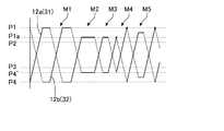
- FIG. 5 shows some operation modes realized by the gas supply unit 10 by the movement of the piston 12, specifically, the movements of both surfaces 12 a and 12 b of the piston 12.
- the solid line indicates the movement of the piston 12 in the compression direction in each of the combustion chambers 31 and 32, and the broken line indicates the movement of the piston 12 in the expansion direction.
- mode M1 the piston 12 moves between the top dead center P1 and the bottom dead center P4, and the linear power generation unit 20, in this example, the first linear power generation unit 210, at the top dead center P1 at the start of combustion for a certain period of time.
- the movement of the piston 12 is restricted, and combustion is performed in a fixed volume state.
- Mode M1 is an example of a compression ignition mode.
- the piston 12 After the start of combustion, the piston 12 is released, and as indicated by broken lines, the gas output ports 17a and 17b are alternately opened at each timing when the combustion chamber side surfaces 12a and 12b of the piston 12 reach the position P2, respectively.
- Drive gas 71 is alternately supplied from the combustion chambers 31 and 32 to the turbine 6. Further, when the surfaces 12a and 12b on the combustion chamber side of the piston 12 alternately reach the position P3, the exhaust port 18 is opened, and the exhaust and the compressed air or mixed gas are alternately (at each timing) in the combustion chambers 31 and 32, respectively. After that, the gas is supplied, and then the piston 12 compresses the combustion chambers 31 and 32 alternately by using the pressure of the combustion gas in the other combustion chambers 32 and 31 as a driving force.
- mode M2 the movement range of the piston 12 is further narrowed and moves between the top dead center P1a and the corresponding bottom dead center P4 ′.
- the movement of the piston 12 at the dead point is restricted for a longer time, the constant volume combustion period is set longer, and the combustion mode is close to the Sabatate cycle or the diesel cycle.
- mode M3 the limit of movement at the dead center of the piston 12 is shortened.
- mode M4 combustion in the combustion chambers 31 and 32 is explosive, and there is no limit of movement of the piston 12, and the combustion mode is the same as in the Otto cycle. Realized.
- the movement amount of the piston 12 by the linear power generation unit 210 can be flexibly set between the maximum dead point P1 and the minimum dead point P1a as in the mode M5.
- the combustion mode (combustion mode) of the combustion chambers 31 and 32 can be changed in units of one cycle, and can be moved continuously in the same combustion mode for a certain period of time.
- the gas supply unit 10 has a configuration similar to a free piston engine in which the piston 12 reciprocates in the cylinder 14 by the combustion pressure obtained when the fuel is burned in the combustion chamber, but is connected to the piston 12.
- the movable magnet 21 is controlled by the first linear power generation unit 210, and is used as a first control unit 610 that controls the position of the piston 12 against the combustion pressure.
- the piston 12 can be moved. Therefore, the engine 5 can flexibly adjust the piston movement cycle, the compression ratio at the time of combustion, and the like, in units of the gas supply unit 10, and supply the driving gas 71 under conditions suitable for driving the turbine 6. it can.
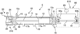
- FIG. 6 shows a different example of the engine 5.
- the shaft 13 connected to the piston 12 extends to the opposite side in the longitudinal direction, and a first control unit 610 that is a mechanical piston control unit 60 is provided in the longitudinal direction outside the gas supply unit 10. ing.
- the first control unit 610 controls the movable portion 61 connected to the piston 12 via the shaft 13, the set of stoppers 63a and 63b that catch and release the movable portion 61, and the positions of the stoppers 63a and 63b.
- a unit 65 In this engine 5, the position of the piston 12 can be controlled by the mechanical first control unit 610, so the linear power generation unit 210 provided on the opposite side of the first control unit 610 is specialized only for linear power generation. It may be a unit.
- the mechanical first control unit 610 and the linear power generation unit 210 may control the piston 12 in cooperation.
- the configuration for mechanically controlling the position and / or movement of the piston 12 via the shaft 13 is not limited to this example.
- the movable magnet 21 of the shaft 13 may be moved or fixed via magnetic force by an electromagnetic coil or magnet that is physically moved by a motor or an air cylinder instead of a linear motor.
- FIG. 7 shows a further different example of the engine 5.
- a first linear power generation unit 210 connected to the piston 12 via the shaft 13 is provided on both sides of the piston 12, that is, on each side of the combustion chambers 31 and 32.
- a configuration in which each first linear power generation unit 210 functions as a first control unit 610 is shown, and electromagnetic force for controlling the piston 12 is generated by two linear power generation units (linear motor units) 210.
- the linear power generation unit 210 is obtained in cooperation and can be provided in a compact and low-cost manner.
- the permanent magnet 26 is arranged at the end of the first linear power generation unit 210 to ensure the function as a shock absorber.
- one unit for example, the unit on the combustion chamber 32 side functions only as the first linear power generation unit 210, and the unit on the opposite combustion chamber 31 side controls the piston 12 as a linear motor unit. You may comprise so that it may function only as the 1st control unit 610. FIG. Since each unit can be specialized for power generation and control, the configuration and control may be simplified.
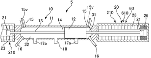
- FIG. 8 shows a further different example of the engine 5.
- a combustion chamber 31 is provided in one of the pistons 12 of the cylinder 11, and a spring 69 is disposed in a sub chamber (second chamber) 39 on the opposite side across the piston 12. Since the combustion chamber 31 is compressed, an opposite force (second force, pressure) is obtained.
- the piston control unit 60 is disposed outside the gas supply unit 10 along the longitudinal direction and is connected to the piston 12 via the shaft 13. In this example, the piston control unit 60 is connected to the gas supply unit 10. It is integrated so as to be integrated.
- the piston control unit 60 is disposed along the cylinder 11 on the outer peripheral side of the combustion chamber 31 and the reaction chamber (second chamber) 39, specifically, on the outer side (outer peripheral side) of the cylinder 11.
- the piston 12 includes magnets 66a and 66b arranged (built-in) at front and rear ends thereof.
- the second control unit 620 includes magnets 68 a and 68 b arranged before and after the cylinder 11 and magnets 67 a and 67 b arranged around the cylinder 11. These magnets may be electromagnets, permanent magnets, or a mixture thereof.
- Magnets 68a and 66a repel and define the top dead center of piston 12, and magnets 68b and 66b repel and define the bottom dead center of piston 12. Further, the positions of the top dead center and the bottom dead center can be controlled by the surrounding magnets 67a and 67b, and the movement of the piston 12 can be restricted.
- the high-pressure driving gas 71 can be efficiently supplied from the gas discharge port 17. Can be discharged.
- the reaction chamber 39 opposite to the combustion chamber 31 across the piston 12 may be used as an area for storing compressed air to be supplied to the combustion chamber 31.
- the compressed air stored in the reaction chamber 39 is compressed when the piston 12 moves to the opposite side due to combustion in the combustion chamber 31, and functions as a damper that softens the rapid movement of the piston 12 together with the spring 69.
- the reaction chamber 39 may include a position sensor (contact sensor, optical sensor, etc.) for detecting the position of the piston 12. Further, when the piston 12 moves to the left side and compresses the compressed air in the combustion chamber 31, it is possible to put further compressed air into the reaction chamber 39, and the pressure and reaction of the combustion chamber 31 across the piston 12.
- the pressure with the chamber 39 can be made as close as possible, and the pressure difference can be reduced and balanced.
- the piston 12 can be moved under the condition that the piston 12 floats between the combustion chamber 31 and the reaction chamber 39. Thereby, it becomes easy to move the piston 12 to the combustion chamber 31 side by the elastic force of the spring 69, and the combustion air in the combustion chamber 31 can be further compressed with a small elastic force.
- combustion air that is near the ignition temperature by a compressor but adiabatically compressed to such an extent that it does not reach the ignition temperature is supplied to the combustion chamber 31 via the reaction chamber 39, and is adiabatically compressed by the piston 12 and combusted to the ignition temperature. The temperature of the air can be raised.
- a metal spring 69 is preferable as a mechanism for obtaining the opposite side force (second force) for driving the piston 12 under such conditions.
- Other types of elastic bodies such as rubber, may be used as long as the conditions such as the movement amount of the piston 12, the elastic force (pressure) for moving, and the temperature are satisfied. It may be a damper having viscoelasticity or a combination of a damper and a spring.
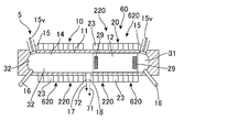
- FIG. 9 shows a further different example of the engine 5.
- the gas supply unit 10 of the engine 5 includes combustion chambers 31 and 32 provided on both sides of the piston 11 of the cylinder 11.
- the gas supply unit 10 includes a second control unit 620 that is disposed on the outer periphery of the combustion chambers 31 and 32 as a piston control unit 60 that controls the position of the piston 12 and controls the position of the piston 12 via a magnetic field.
- the second control unit 620 includes a plurality of electromagnets (fixed coils) arranged around the cylinder 11 along the longitudinal direction of the cylinder 11, that is, the moving direction (reciprocating direction) of the piston 12. 23.
- the piston 12 includes permanent magnets 29 arranged or built in both ends thereof.
- electromagnets 23 are on / off and controlled in polarity by a management unit (control unit) 50, and control the movement of the piston 12 via a magnetic field. That is, the second control unit 620 includes a function as a linear motor (linear actuator) that controls the movement of the piston 12 via a magnetic field.
- the electromagnet 23 constituting the second control unit 620 constitutes a second linear power generation unit 220 that functions as the linear power generation unit 20 that regenerates power from the movement of the piston 12.
- the gas supply unit 10 of the engine 5 includes a piston control unit 60 that controls the movement of the piston 12, similar to the gas supply unit 10 of the engine 5 described above, and the piston control unit 60 generates power by the movement of the piston 12. It also serves as the linear power generation unit 20 that performs the above.
- the linear power generation unit 20 that generates power by the movement of the piston 12 may also serve as the piston control unit 60 that controls the movement of the piston 12.
- the piston control unit 60 and the linear power generation unit 20 of the gas supply unit 10 include an electromagnet (fixed coil) 23 disposed around the cylinder 11, and these serve as a second control unit 620 as a second linear motor and a second linear motor.
- the two linear power generation units 220 are configured to cooperate with the movement of the piston 12 through a magnetic force (magnetic field).
- the piston 12 is reciprocated by the plurality of electromagnets 23, the air in the combustion chambers 31 and 32 is alternately compressed, and combustion is alternately generated in the combustion chambers 31 and 32.
- the driving gas 71 is alternately supplied from the combustion chambers 31 and 32 to the turbine 6.
- the specific movement of the piston 12 and the process of releasing the driving gas 71 and the exhaust gas 72 through the nozzles (output port, exhaust port) 17 and 18 are the same as those of the gas supply unit 10 described above. In the following, description of common parts will be omitted.
- the gas supply unit 10 shown in FIG. 9 outputs the driving gas 71 and the exhaust gas 72 at the center in the longitudinal direction of the cylinder 11, and includes the nozzle 17 (18) common to the combustion chambers 31 and 32. Therefore, when the piston 12 moves to the combustion chamber 31 side and the nozzle 17 is opened, the high-pressure driving gas 71 is discharged from the combustion chamber 32 and supplied to the turbine 6 via the gas supply line 19. When the pressure in the combustion chamber 32 decreases, the outlet of the nozzle 17 is switched to the exhaust gas line 78 by a valve or the like, and the exhaust gas 72 is released to the outside air. Thereafter, when fuel is started in the combustion chamber 31, the piston 12 moves toward the combustion chamber 32, and the common nozzle 17 is closed by the piston 12. When the piston 12 further moves to the combustion chamber 32 side, the common nozzle 17 is opened, and the driving gas 71 is released from the combustion chamber 31 as described above.
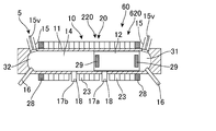
- FIG. 10 shows a further different example of the engine 5.
- the second control unit 620 of the gas supply unit 10 of the engine 5 includes permanent magnets 28 disposed at both ends in addition to the electromagnet 23 that controls the movement of the piston 12.
- the permanent magnets 28 at both ends of the second control unit 620 are provided with magnetic poles repelling each other with the permanent magnets 29 attached to the piston 12, and reduce the impact at the top dead center and bottom dead center of the piston 12. The start of the piston 12 can be promoted.
- FIG. 11 shows a further different example of the engine 5.
- the gas supply unit 10 of the engine 5 includes independent nozzles (gas output ports) 17a and 17b in the combustion chambers 31 and 32 of the cylinder 11, respectively.
- Each of the nozzles 17a and 17b also functions as the exhaust nozzle 18.
- the timing at which the nozzles 17a and 17b are opened by the reciprocating motion of the piston 12 can be set to an early timing during combustion.
- FIG. 12 shows a further different example of the engine 5.
- the gas supply unit 10 of the engine 5 includes nozzles 17 a and 17 b for output of the driving gas 71 independent of the combustion chambers 31 and 32 of the cylinder 11, and further includes an exhaust nozzle 18 in the center of the cylinder 11. .
- the exhaust nozzle 18 is a nozzle common to the combustion chambers 31 and 32.
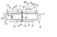
- FIG. 13 shows a further different example of the engine 5.
- the second control unit 620 of the gas supply unit 10 of the engine 5 includes a permanent magnet 28 disposed substantially at the center of the cylinder 11 in addition to the electromagnet 23 that controls the movement of the piston 12.
- the permanent magnet 28 in the center of the second control unit 620 may be a magnetic pole repelling each other with the permanent magnet 29 attached to the piston 12 or may be a magnetic pole attracting.
- the combination, position, number, etc. of the electromagnet 23 and the permanent magnet 28 employed in the piston control unit 60 for controlling the movement of the piston 12, specifically, the first control unit 610 and the second control unit 620 are as described above. It is not limited to the example.
- the piston control unit 60 is a combination of a first control unit 610 that controls the piston 12 via the shaft 13 and a second control unit 620 that controls the piston 12 via the cylinder 11 via a magnetic field. Also good.
- the piston control unit 60 may be capable of variably controlling the stroke of the piston 12 or may be controlled so that the stroke becomes constant.
- Each of the control units 610 and 620 may be configured only by the electromagnet 23, may be a combination of the permanent magnet 28 and the electromagnet 23, may be configured only by the permanent magnet 28, and the position of the magnet. And the number can be appropriately selected. Further, the piston control unit 60 may include a mechanism that can directly change the positions and number of the permanent magnets 28 and the electromagnets 23.
- FIG. 14 schematically shows the timing at which the driving gas 71 can be supplied to the turbine 6.
- the driving gas 71 can be continuously supplied to the turbine 6.
- it is necessary to drive a compressor having a large compression ratio with a turbine and it may be difficult to improve combustion efficiency.
- it is possible to move the gas supply unit in four cycles it is difficult to stably rotate the turbine 6 because the driving gas 71 is intermittently output.
- the supply interval of the drive gas 71 can be reduced.
- the driving gas 71 can be supplied to the turbine 6 almost continuously. Further, by using the piston 12, it is easy to increase the compression ratio in the combustion chambers 31 and 32, and the combustion efficiency is also easily improved.
- the engine 5 includes a plurality of gas supply units 10, and the driving gas 71 is supplied to the turbine 6 more continuously by appropriately setting the timing (phase) at which the driving gas 71 is output therefrom.
- the turbine 6 can be rotated more stably.
Abstract
ピストン(12)の往復直線運動に伴い駆動用の燃焼ガスを供給するガス供給ユニット(10)を有するエンジン(5)を提供する。ガス供給ユニット(10)は、ピストンの第1の側に設けられた第1の燃焼室(31)と、第1の燃焼室で生成された高圧の燃焼ガスを駆動用に供給する第1のガス出力口(17)と、ピストンを挟んだ第2の側に設けられ、ピストンを第1の側に移動する第2の力を生成する第2の燃焼室(32)とを含む。エンジン(5)は、さらに、第1の燃焼室における燃焼により移動するピストンの第1の力および上記第2の力に対抗してピストンの位置を制御するピストン制御ユニット(60)を有する。
Description
本発明は、燃焼室内で生成された高圧の燃焼ガスを動力に使うエンジンに関するものである。
国際公開WO2015/159956号公報には、燃焼ガスを駆動力として噴出するエンジンを提供することが記載されている。このエンジンは、燃焼室と、燃焼室に燃料および空気を混合して供給する燃料供給路と、燃焼室の混合ガスに点火するイグナイタと、燃焼室から燃焼ガスを、ノズルを介して噴出するガス放出路と、ガス放出路を開閉する開閉装置とを有する。ガス放出路は、開閉装置により、点火の直前、点火と同時、または点火の直後に開放できる。
ピストンを用いたエンジンであって、燃焼ガスを駆動力としてタービンなどに供給するタイプのエンジンにおいて、燃焼ガスを供給するタイミングや燃焼効率などをさらに容易に制御できるエンジンが求められている。
本発明の一態様は、ピストンの往復直線運動に伴い駆動用の燃焼ガスを供給するガス供給ユニットを有するエンジンである。ガス供給ユニットは、ピストンの第1の側に設けられた第1の燃焼室と、第1の燃焼室で生成された高圧の燃焼ガスを駆動用に供給する第1のガス出力口と、ピストンを挟んだ第2の側に設けられ、ピストンを第1の側に移動する反対側の第2の力を生成する第2の室とを含む。エンジンは、さらに、第1の燃焼室における燃焼により移動するピストンの第1の力および上記第2の力に対抗してピストンの位置を制御するピストン制御ユニットを有する。直線的に動くピストンの位置を制御することにより、ピストンにより第1の燃焼室の容積(体積)を縮小して燃焼室内の気体を断熱圧縮する際の圧縮比、燃焼サイクルなどを制御できる。燃焼室内の気体は、燃料と空気との混合気体であってもよく、圧縮した段階でイグナイタなどにより着火させてもよい。また、燃焼室内の気体は空気であってもよく、燃料を噴射して圧縮点火させてもよい。
ガス供給ユニットは、第1の燃焼室内の低圧の燃焼ガスを排気する排気口を含んでもよい。第1の燃焼室内における燃焼ガスと混合気体または空気との置換効率を向上できる。
第2の力はバネや磁気により生成される力(反動)であってもよい。典型的な第2の室(副室)は、第2の燃焼室であり、ガス供給ユニットは、第2の燃焼室で生成された高圧の燃焼ガスを駆動用に供給する第2のガス出力口を含んでもよい。第1および第2の燃焼室から交互に高圧の燃焼ガスを駆動用に供給でき、ピストンの動きの1サイクル単位でガス供給ユニットから駆動用の燃焼ガスを供給できる。
ピストン制御ユニットは、ピストンの位置を機械的に、または磁気的に直接制御するものであってもよい。ピストン制御ユニットは、第1の燃焼室および第2の室の外側に配置され、ピストンの位置を、ピストンに接続されたシャフトを介して制御する第1の制御ユニットを備えていてもよい。エンジンは、ピストンとシャフトを介して接続された第1のリニア発電ユニットを有していてもよい。第1のリニア発電ユニットが第1の制御ユニットとしての機能を含んでいてもよい。第1のリニア発電ユニットはピストンを駆動してエンジンを始動する第1のリニアモータとしての機能を含んでいてもよい。ピストン制御ユニットは、ピストンの第1の力または反対側に働く第2の力に対抗してピストンの位置を制御するので、リニア発電ユニットにより、ピストンの位置を制御に要する、動力および/または反対側に働く動力に対抗する力を電気エネルギーとして回生できる。
ピストン制御ユニットは、第1の燃焼室および第2の室(副室)の外周に配置され、ピストンの位置を、磁場を介して制御する第2の制御ユニットを含んでもよい。エンジンは、第1の燃焼室および第2の室の外周に配置され、ピストンと磁場を介して接続された第2のリニア発電ユニットを有していてもよい。第2のリニア発電ユニットは第2の制御ユニットとしての機能を含んでもよい。第2のリニア発電ユニットはピストンを駆動して当該エンジンを始動する第2のリニアモータとしての機能を含んでいてもよい。
エンジンは、第1のガス出力口から高圧の燃焼ガスが供給されるガスタービンユニット(ガスタービン)を有していてもよい。典型的なガスタービンユニットは、ラジアルタービンを含み、複数のガス供給ユニットをラジアルタービンの周囲に沿って配置してもよい。
本発明の一態様は、上記のエンジンと、ガスタービンユニットに接続された発電機とを有する発電装置である。ガスタービンと発電機とは直結されていてもよく、ギアなどを介して接続されていてもよい。
図1に、複数のガス供給ユニット10とガスタービンユニット6とを備えたエンジン5と、ガスタービンユニット(例えばラジアルタービン、以降ではタービン)6により回転駆動される発電機3とを含む発電装置(発電ユニット)1を示している。発電ユニット1は、タービン6に対し長手方向に直線的につながった発電機3と、タービン6およびタービン排気ノズル7を中心として、その周囲に配置された複数のガス供給ユニット10と、ガス供給ユニット10と一対一に設けられたリニア発電ユニット20とを含む。それぞれのリニア発電ユニット20は、ガス供給ユニット10の長手に接続され、ピストン制御ユニット60としての機能を兼ねている。これらのタービン6、発電機3、複数のガス供給ユニット10およびリニア発電ユニット20は、全体が1つの装置として設置または可搬できる状態で提供されている。さらに、発電ユニット1は、ピストン制御ユニット60を兼ねたリニア発電ユニット(リニアモーターユニット)20およびガス供給ユニット10を介して発電ユニット1を制御する管理ユニット50と、ガス供給ユニット10に、燃焼用の燃料および空気を供給する燃料供給ユニット80とを含む。
ガスタービンユニット6は、ラジアルタービン(半径流タービン)であってもよく、軸流タービンであってもよく、ラジアルタービンと軸流タービンとの組み合わせであってもよい。このエンジン5においては、複数、例えば4つのガス供給ユニット10がタービン6の周囲の対称な位置に、例えば90度ピッチで配置され、異なったタイミングで、または同期して駆動用の燃焼ガスをタービン6に供給する。ガス供給ユニット10の数は4つに限定されず、3つ以下であってもよく、5つ以上であってもよく、配置も90度ピッチに限定されない。
図2に、タービン6に駆動用の高圧の燃焼ガス71を供給するガス供給ユニット10と、ガス供給ユニット10のピストン12を制御するピストン制御ユニット60を兼ねたリニア発電ユニット20との構成を、断面を用いて、模式的ではあるが、さらに詳しく示している。ガス供給ユニット10は、ピストン12が内部14で往復直線運動を行うシリンダ11を含み、シリンダ11内のピストン12の一方の側(第1の側、本図では右側)に第1の燃焼室31が形成され、ピストン12の他方の側(第2の側、本図では左側)に第2の燃焼室32が形成される。
ピストン制御ユニット60を兼ねたリニア発電ユニット20は、ガス供給ユニット10の長手方向に一体となるように接続されており、この例では、ガス供給ユニット10の左側に隣接して設けられている。リニア発電ユニット20は、筒型のハウジング25と、発電時には発電コイルとして機能し、モーター駆動時には固定電磁石として機能するように、ハウジング25の内部に長手方向(軸方向)に配置された複数の固定コイル(電磁石)23と、固定コイル23の内部で軸方向に沿って動く可動磁石(可動電磁石)21とを含み、可動磁石21がピストン12とシャフト(ロッド)13により連結されている。ハウジング25の内部の両端には、可動磁石21の端末での動きを緩和するショックアブソーバーとして機能するコイルバネ24が設けられている。コイルバネ24の代わりに、あるいはコイルバネ24とともに、両端の電磁コイル23aの磁極を可動磁石21と反対に設定してピストン12の両端における動きあるいは衝撃を緩和または吸収するようにしてもよい。可動磁石21は永久磁石であってもよく、両端の固定コイル(電磁石)23aは、可動磁石21と反発する磁極を備えた永久磁石であってもよい。また、固定コイル23は、すべてが電磁石でなくてもよく、ピストン12の制御に適した位置の磁石を、適切な磁極を備えた永久磁石に置き換えてもよい。
したがって、この例では、ピストン制御ユニット60は、第1の燃焼室31および第2の燃焼室32の外側に配置され、ピストン12の位置を、ピストン12に接続されたシャフト13を介して制御する第1の制御ユニット610を含む。また、リニア発電ユニット20は、ピストン12とシャフト13を介して接続された第1のリニア発電ユニット210を含む。さらに、第1のリニア発電ユニット210が第1の制御ユニット610としての機能を含み、第1のリニア発電ユニット210はピストン12を駆動して当該エンジン5、具体的には各ガス供給ユニット10を始動する第1のリニアモータとしての機能を含む。また、このエンジン5においては、第1の燃焼室31および第2の燃焼室32が、互いに、燃焼によりピストン12に発生する力(第1の力)に対して反対側に働く力(第2の力)を生成する第2の室(副室)として機能する。
ガス供給ユニット10は、シリンダ11の内部14の第1の端(右端)および第2の端(左端)の近傍に、燃料供給ユニット80からの空気、または空気および燃料の混合体を導入する吸気口15と、吸気口15を開閉する吸気バルブ15vと、燃料噴射装置16とを含む。燃料噴射装置16は、点火装置を兼ねる。ピストン12の移動量により燃料の着火温度まで燃焼室31および32内の圧縮空気の温度を高くできる場合は、燃料噴射装置16から燃料を噴射することにより、それぞれの燃焼室31および32内において燃焼を開始できる(圧縮点火モード)。断熱圧縮の過程において圧縮空気の圧縮率を着火温度まで上げることが難しい場合は、燃料供給ユニット80は圧縮空気の代わりに、燃料との混合空気を燃焼室31および32に供給し、燃料噴射装置16が点火装置として機能して燃焼室31および32内において燃焼を開始できる(火花点火モード)。圧縮点火モードにおいては、近年開発が進んでいる予混合圧縮自動着火(HCCI、Homogeneous Charge Compression Ignition)に関する燃焼技術を適用できる。
ガス供給ユニット10は、第1の燃焼室31から高圧の燃焼ガスを駆動ガス71としてタービン6に供給する第1のガス出力口17aと、第2の燃焼室32から高圧の燃焼ガスを駆動ガス71としてタービン6に供給する第2のガス出力口17bと、それぞれの燃焼室31および32から低圧の燃焼ガス(排気ガス)72を排気する共通の排気口18とを含む。
排気口18はシリンダ11の長手方向のほぼ中央に設けられており、ピストン12が排気口18を通過することによりそれぞれの燃焼室31および32から排ガスライン78を介して燃焼ガスを大気へ排気する。排ガスライン78には、ピストン12に移動とは独立してそれぞれの燃焼室31および32を与圧するための制御弁38と、排ガス72のエネルギーを用いて吸気を加圧するターボチャージャー79とが設けられている。
第1のガス出力口17aおよび第2のガス出力口17bはそれぞれ、シリンダ11の長手方向の中央からそれぞれの端にシフトした位置であって、中央に対して対称な位置に設けられている。それぞれのガス出力口17aおよび17bは、ピストン12を挟んでシリンダ内14に形成される第1の燃焼室31および第2の燃焼室32において、燃焼後の早い段階でピストン12が移動(通過)する位置に設けられている。したがって、このガス供給ユニット10においては、ピストン12がそれぞれのガス出力口17aおよび17bを開閉する機能を含む。ガス出力口17aおよび17bは、ガス供給ライン19を介してタービン6に高圧の駆動ガス71を供給する。ガス供給ライン19は、臨界ノズルとしての機能を備えていてもよい。また、ガス供給ライン19には、相互の燃焼室31および32からの駆動ガス71、および他のガス供給ユニット10からの駆動ガス71の逆流を防止するためのバルブまたは他の逆流防止用の機構37が設けられている。
このガス供給ユニット10におけるガス出力口17aおよび17b、排気口18の配置および構成は一例であり、排気口18は燃焼室毎に設けてもよく、ガス出力口17および排気口18は、各燃焼室に共通に設けてもよく、管理ユニット50の制御あるいは適当な圧力制御弁により、燃焼室からのガスの出力先をガス供給ライン19と排ガスライン78とに切り替えることも可能である。また、ピストン12の移動によりガス出力口17aおよび17b、排気口18を開閉する代わりに、管理ユニット50の制御あるいは適当な機構による制御により動作するバルブにより開閉してもよい。
エンジン5を制御する管理ユニット50は、第1のリニア発電ユニット210の固定コイル23の極と磁場とを制御することにより、可動磁石21の運動、例えば、速度および停止位置を制御する。これにより、可動磁石21とつながったピストン12のシリンダ内14の運動、例えば速度および停止位置(死点)を制御する。典型的には、ピストン12の停止位置(上死点および下視点)を制御する。したがって、第1のリニア発電ユニット210がピストン制御ユニット60(第1の制御ユニット610)として機能する。管理ユニット50は、さらに、燃焼室31および32における燃焼前後のピストン12の停止時間、移動量または移動速度を、リニア発電ユニット210の磁場を制御することにより、燃焼による動力(力、圧力)に逆らって制御することができる。管理ユニット50は、さらに、リニア発電ユニット210をリニアモータとして使用し、ピストン12を駆動することにより、内燃機関であるガス供給ユニット10を起動(始動)するスタータとして機能させる。
図3に、このガス供給ユニット10の典型的な動作を示している。このガス供給ユニット10は、排気口18を中心として対称に燃焼室31および32が設けられ、ピストン12が直線往復して、ピストン12を挟んで両側に設けられた、対称な構成の燃焼室31および32で圧縮-着火-燃焼を交互に繰り返し行う。
まず、図2に示したように、ピストン12が右端の死点P1に達しており、右側の第1の燃焼室31で着火燃焼が起きると、それが左側の燃焼室32においては反対側の力(第2の力)となり、ピストン12は左側に移動し、左側の燃焼室32の空気または混合気体を圧縮する。したがって、燃焼室31および32が、反対側の燃焼室32および31に対する第2の室(副室、反動を生成する室)となっている。具体的には、右側の燃焼室31においては燃焼が開始されると、図3(a)に示すように燃焼室31内で生成される燃焼ガスの圧力(膨張するガス)に押されてピストン12が左側に移動し、ピストン12の第1の燃焼室31側の面、すなわち、右側の面12aが位置P2に達し、ピストン12の移動により第1のガス出力口17aが開くと、開いた第1のガス出力口17aから高圧の燃焼ガスが駆動ガス71としてタービン6に供給され、タービン6を駆動する。
図3(b)に示すように、燃焼室31内で生成される燃焼ガスの圧力(膨張するガス)に押されてピストン12がさらに左側に移動し、右側の面12aが位置P3に達し、ピストン12の移動により排気口18が開くと、燃焼室31に残存していた低圧の燃焼ガスが排気ガス72として排気される。それとほぼ同時に吸気バルブ15vが開き、圧縮空気または燃料との混合気体が燃焼室31内に供給される。燃料供給ユニット80から燃焼室31に供給される空気または混合気体は、ターボチャージャー79により加圧または圧縮された気体であり、排気口18が開いて燃焼室31の圧力が低下すると即座に燃焼室31に注入できる。燃焼室31への注入効率を上げ、また、燃焼室31における圧縮効率を上げるためにターボチャージャーに加え、またはターボチャージャーとは別に、エンジン5は、圧縮用のコンプレッサーを備えていてもよい。コンプレッサーは電動であってもよく、タービン6に駆動されるタイプであってもよい。
一方、ピストン12を挟んで反対側の、左側の燃焼室32においては、図3(a)および(b)の状態で、右側の燃焼室31における燃焼ガスの圧力が、ピストン12に対して反対側に働く力(第2の力)となり、ピストン12が左側へ移動し、燃焼室32に供給されている空気または混合気体が圧縮される。図3(c)に示すように、ピストン12の左側の面12bが燃焼室32の上死点に対応する位置P1に達すると、第1の制御ユニット610を兼ねた第1のリニア発電ユニット210が、ピストン12を左側へ移動する(加圧する)ように働く、右側の燃焼室31の燃焼ガスの圧力(動力、力、第1の力)に対抗して、磁場を用いてピストン12の停止位置を制御する。この際、リニア発電ユニット210は、ピストン12の動きにより発電を行ってもよい。発電ユニット210によりエネルギー回生を行い、不図示のバッテリなどに電力を蓄えて、その後のピストン12の位置制御のために使うことができる。なお、ピストン12の左側の面12bが上死点P1に達すると、ピストン12の右側の面12aは下死点に対応する位置P4に達する。
図3(c)において、左側の燃焼室32で着火燃焼が行われると、燃焼によりガスが膨張し、燃焼ガスの圧力によりピストン12が右側に移動する。図3(d)に示すように、ピストン12の左側の面12bが位置P2に達し、ピストン12の移動により第2のガス出力口17bが開くと、開いた第2のガス出力口17bから高圧の燃焼ガスが駆動ガス71としてタービン6に供給され、タービン6を駆動する。右側の燃焼室31においては、ピストン12により排気口18が閉じられ、左側の燃焼室32の燃焼ガスの圧力を反対側の力(第2の力)として、右側の燃焼室31内の空気または混合気体が圧縮される。排気口18からの排気を停止するタイミングは排ガスライン78に設けられたバルブ38により制御してもよい。このような動作を繰り返すことにより、ガス供給ユニット10から高圧の駆動ガス71が、左右の燃焼室31および32から交互に、ほぼ連続してタービン6に供給され、タービン6を駆動する。
エンジン5においてはこのようなシリンダ内14におけるピストン12の動きを、ピストン制御ユニット60(第1の制御ユニット610)としての機能を有するリニア発電ユニット20(第1のリニア発電ユニット210)で、モニターしながら制御することができる。ピストン12の動きを制御する1つのモードは上死点の位置を変えることである。図4に上死点を位置P1から位置P1aに設定したときのガス供給ユニット10の動作を示している。図4(a)に示すように、リニア発電ユニット210における可動磁石21の停止位置を固定コイル23により生成される磁場を制御することによりピストン12の右側の面12aの停止位置を、位置P1より中央によった位置P1aに設定し、燃焼室31における空気または混合気体の圧縮率を変えることができる。この場合も、燃焼室31で生成された高圧の燃焼ガスによりピストン12が左側に動いて右側の面12aが位置P2に達すると、図4(b)に示したように、第1のガス出力口17aが開いて駆動ガス71としてタービン6に供給される。また、同時に、左側の燃焼室32の空気または混合気体はピストン12により圧縮される。
図4(c)に示すように、ピストン12がさらに左側に動いて右側の面12aが位置P3に達すると、排気口18が開いて燃焼室31から燃焼ガスが排気され、同時に、空気または混合ガスが燃焼室31に供給される。この際、ピストン12の左側の面12bが上死点である位置P1aに達していると、燃焼室32で燃焼が行われ、図4(d)に示すように、ピストン12が右側に動いて、燃焼室32で生成された高圧の燃焼ガスが第2のガス出力口17bから駆動ガス71としてタービン6に供給される。
リニア発電ユニット210は、さらに、ピストン12の停止時間、例えば、各上死点における停止時間を制御することも可能である。また、ピストン12が上死点から、駆動ガス71として出力する位置P2まで移動する時間あるいはタイミングを制御することも可能である。例えば、ピストン12を上死点P1からリリースするタイミングがガス出力口17aおよび17bを開にするタイミングに繋がる。出力口17aおよび17bをオープンして駆動ガス71をタービン6に供給するタイミングは、燃焼室31および32で生成される燃焼ガスを駆動ガス71として最も効率よくタービン6を駆動できるタイミングであればよく、燃焼室31および32で燃焼が開始された後、燃焼が継続している途中であってもよく、燃焼が終了した後であってもよい。
典型的なタイミングは燃焼室31で燃焼が継続している途中でピストン12をリリースして動かすとともにガス出力口17aをオープンすることである。同様に、次に燃焼室32で燃焼が継続している途中でピストン12をリリースしてガス出力口17bをオープンすることができる。これらのタイミングで出力口17aおよび17bをそれぞれオープンすることにより、それぞれの燃焼室31および32における燃焼を、定積燃焼から定圧燃焼に移行でき、爆発的な燃焼に対して燃焼時間を延ばし、駆動ガス71の供給時間を延長できる。燃焼終了後は、燃焼ガスは断熱膨張し、駆動ガス71として燃焼室31および32からタービン6に供給される。
このガス供給ユニット10は、ピストン12がシリンダ11の内部14で直線的に往復運動する燃焼ユニットであり、ピストン12が反対側の燃焼室における燃焼ガスの圧力を用いてそれぞれの燃焼室31および32に供給されている圧縮空気をさらに圧縮(断熱圧縮)する。断熱圧縮の過程において圧縮率を十分高くすることができ、燃料の着火温度まで燃焼室31および32内の圧縮空気の温度を高くできる場合は、燃料噴射装置16から燃料を噴射することにより燃焼室31および32内において燃焼を開始できる(圧縮点火モード)。断熱圧縮の過程において圧縮空気の圧縮率を着火温度まで上げることが難しい場合は、圧縮空気の代わりに、燃料との混合空気を燃焼室31および32に供給し、燃料噴射装置16を点火装置として使用し、燃焼室31および32内において燃焼を開始できる(火花点火モード)。燃焼室31および32における圧縮率は、ピストン12の停止位置またはストロークをピストン制御ユニット60(リニア発電ユニット20)により制御できる。燃焼途中でガス出力口17aおよび17bをオープンすることにより、燃焼室31および32においては間欠的な燃焼が繰り返されるが、タービン6に対しては、高温高圧の燃焼ガス(排気ガス)71を、より連続的に供給できる。
いずれの場合も、間欠燃焼サイクルであり、理論的には定圧で燃焼が行われるディーゼルエンジンサイクル、定積で燃焼が行われるオットーサイクル、あるいはその両方の特徴を持つサバテサイクルとして呼ばれる状態が実現される。間欠燃焼サイクルにおいては、燃焼室31および32内の燃焼時の圧力を、生成される燃焼ガス自身、またはピストン12の位置、移動速度などを制御することにより高めることが可能であり、高温高圧の燃焼ガスを得やすい。さらに、このエンジン5では、火花点火モードも、空気または混合気体を圧縮することにより自己着火させる圧縮点火モードにも対応でき、圧縮点火は燃焼時間を延長でき、タービン6に燃焼ガスを駆動ガス71として連続的に供給できる時間を延長する一例と考えられている。例えば、近年開発されている予混合圧縮自動着火(HCCI)技術を使用することも可能である。
また、それぞれの燃焼室31および32における燃焼状態、燃焼サイクルの速度(周期)は、燃焼室31および32に供給する燃料量(混合比)を変えたり、燃焼室31および32内において着火するタイミングを変えたり、リリーフバルブなどの燃焼室31および32内の圧力を制御する機器を設けたり、ピストン12を移動する長さを制御するなどのピストン12の動きを制御することによりフレキシブルに制御できる。このため、燃料としては、軽油、ガソリン、アルコール、水素など様々なものを使用できる。
図5に、ガス供給ユニット10で実現されるいくつかの運転モードを、ピストン12の動き、具体的には、ピストン12の両面12aおよび12bの動きにより示している。実線は、各燃焼室31および32において、ピストン12の圧縮方向への移動を示しており、破線は、ピストン12の膨張方向への移動を示している。モードM1では、ピストン12が上死点P1および下死点P4との間を動き、リニア発電ユニット20、本例では第1のリニア発電ユニット210により、上死点P1においてに燃焼開始時に一定時間、ピストン12の移動が制限され、定積状態で燃焼が行われる。モードM1は圧縮点火モードの一例である。燃焼開始後、ピストン12はリリースされ、破線で示すように、ピストン12の燃焼室側の面12aおよび12bがそれぞれ位置P2に達するそれぞれのタイミングで、交互にガス出力口17aおよび17bが開いて、交互に燃焼室31および32から駆動ガス71がタービン6に供給される。さらに、ピストン12の燃焼室側の面12aおよび12bが交互に位置P3に達すると排気口18が開いて燃焼室31および32それぞれにおいて、交互に(それぞれのタイミングで)排気と、圧縮空気または混合ガスの供給とが行われ、その後、ピストン12は他方の燃焼室32および31の燃焼ガスの圧力を駆動力として、燃焼室31および32を交互に圧縮する。
モードM2では、ピストン12の移動範囲がさらに狭く制限され、上死点P1aと、それに対応する下死点P4´との間を動く。モードM2では、ピストン12の死点における動きがより長く制限され、定積燃焼期間が長く設定されておりサバテサイクルまたはディーゼルサイクルに近い燃焼形態としている。モードM3では、ピストン12の死点における移動の制限が短くなり、モードM4では、燃焼室31および32における燃焼が爆発的でピストン12の移動の制限はなく、オットーサイクルのように、燃焼形態が実現される。
リニア発電ユニット210によるピストン12の移動量の制限は、モードM5のように、最大の死点P1と最小の死点P1aとの間でフレキシブルに設定できる。また、燃焼室31および32の燃焼モード(燃焼形態)を1サイクル単位で変更することも可能であり、一定の時間、連続して同じ燃焼モードで動かすことも可能である。
このように、ガス供給ユニット10は、燃焼室で燃料を燃焼した際に得られる燃焼圧力によりシリンダ内14で、ピストン12が往復動するフリーピストンエンジンに近い構成であるが、ピストン12に繋がった可動磁石21を、第1のリニア発電ユニット210で制御し、ピストン12の位置を燃焼圧力に逆らって制御する第1の制御ユニット610として使用することで、シリンダ内14の所望の位置を死点としてピストン12を動かすことができる。したがって、エンジン5においては、ガス供給ユニット10の単位で、ピストンの運動周期や、燃焼時の圧縮比などをフレキシブルに調整可能であり、タービン6の駆動に適した条件の駆動用ガス71を供給できる。
図6に、エンジン5の異なる例を示している。このエンジン5においては、ピストン12とつながるシャフト13が長手方向の反対側にも伸び、ガス供給ユニット10の外の長手方向に機械式のピストン制御ユニット60である第1の制御ユニット610が設けられている。第1の制御ユニット610は、シャフト13を介してピストン12とつながった可動部61と、可動部61をキャッチアンドリリースする1組のストッパ63aおよび63bと、ストッパ63aおよび63bの位置を制御する管理ユニット65とを含む。このエンジン5においては、機械式の第1の制御ユニット610によりピストン12の位置を制御できるので、第1の制御ユニット610の反対側に設けられたリニア発電ユニット210は、リニア発電にのみ特化したユニットであってもよい。また、リニア発電ユニット210がピストン制御ユニット60としての機能を含む場合は、機械式の第1の制御ユニット610とリニア発電ユニット210とが協働でピストン12を制御してもよい。ピストン12の位置および/または動きを、シャフト13を介して機械的に制御する構成は、本例に限定されない。例えば、シャフト13の可動磁石21をリニアモータの代わりに、モーターあるいはエアーシリンダー等により物理的に移動する電磁コイルまたは磁石により、磁力を介して動かしたり固定したりしてもよい。
図7に、エンジン5のさらに異なる例を示している。このエンジン5においては、ピストン12の両側、すなわち燃焼室31および32のそれぞれの側に、ピストン12とシャフト13を介して繋がった第1のリニア発電ユニット210が設けられている。本例においては、それぞれの第1のリニア発電ユニット210が第1の制御ユニット610として機能する構成を示し、ピストン12を制御するための電磁力を2つのリニア発電ユニット(リニアモーターユニット)210により協働で得られ、リニア発電ユニット210をコンパクトで低コストに提供できるようにしている。また、第1のリニア発電ユニット210の端に永久磁石26を配置してショックアブソーバーとしての機能を確保している。これに対し、一方のユニット、例えば燃焼室32の側のユニットが第1のリニア発電ユニット210としてのみ機能し、反対側の燃焼室31の側のユニットが、リニアモーターユニットとしてピストン12を制御する第1の制御ユニット610としてのみ機能するように構成してもよい。それぞれのユニットを発電用および制御用に特化できるので構成および制御を簡易にできる可能性がある。
図8に、エンジン5のさらに異なる例を示している。このエンジン5は、シリンダ11のピストン12の一方に燃焼室31が設けられ、ピストン12を挟んだ反対側の副室(第2の室)39にはバネ69が配置されてピストン12を介して燃焼室31を圧縮するため反対側の力(第2の力、圧力)が得られるようになっている。また、上記の例では、ピストン制御ユニット60がガス供給ユニット10の外に、長手方向に沿って配置され、ピストン12とはシャフト13で接続されていたが、この例では、ガス供給ユニット10に一体となるように組み込まれている。具体的には、ピストン制御ユニット60は燃焼室31および反動室(第2の室)39の外周側、具体的にはシリンダ11の外側(外周側)にシリンダ11に沿って配置され、磁場を介してピストン12の位置を制御する第2の制御ユニット620を含む。ピストン12は、その前後の端に配置(内蔵)された磁石66aおよび66bを含む。第2の制御ユニット620は、シリンダ11の前後に配置された磁石68aおよび68bと、シリンダ11の周囲に配置された磁石67aおよび67bとを含む。これらの磁石は、電磁石であってもよく永久磁石であってもよく、それらを混在しても良い。磁石68aおよび66aは反発することによりピストン12の上死点を規定し、磁石68bおよび66bは反発することによりピストン12の下死点を規定する。また、周囲の磁石67aおよび67bにより、上死点および下死点の位置を制御したり、ピストン12の移動を制限したりすることができ、ガス排出口17から効率よく高圧の駆動ガス71を排出できる。
ピストン12を挟んだ燃焼室31と反対側の反動室39は燃焼室31に供給するための圧縮空気を格納する領域として使用してもよい。反動室39に格納された圧縮空気は、燃焼室31内における燃焼によりピストン12が反対側に移動したときに圧縮され、バネ69とともにピストン12の急激な動きを和らげるダンパーとしての機能を果たす。反動室39には、ピストン12の位置を検出するための位置センサー(接触センサー、光学的センサーなど)を含んでいてもよい。また、ピストン12が左側に移動して燃焼室31内の圧縮空気を圧縮する際は、反動室39にさらに圧縮空気を入れることも可能であり、ピストン12を挟んだ燃焼室31の圧力と反動室39との圧力をできるだけ近づけて圧力差を少なくしてバランスさせることができる。すなわち、バネ69の弾性力がなければ、ピストン12が燃焼室31と反動室39との間でフローティングするような条件で動かすことができる。これにより、バネ69の弾性力によりピストン12を燃焼室31の側に移動させることが容易となり、少ない弾性力で燃焼室31内の燃焼空気をさらに圧縮できる。例えば、コンプレッサーで着火温度近くではあるが、着火温度まで至らない程度に断熱圧縮した燃焼空気を、反動室39を経由して燃焼室31に供給し、ピストン12で断熱圧縮して着火温度まで燃焼空気の温度を上げることができる。
このような条件でピストン12を駆動する反対側の力(第2の力)を得る機構としては金属製のバネ69が好ましい。ピストン12の移動量、移動するための弾性力(圧力)、温度などの条件を満足するものであれば、他のタイプの弾性体、例えば、ゴム等であってもよい。粘弾性を備えたダンパー、またはダンパーとバネとの組み合わせであってもよい。
図9に、エンジン5のさらに異なる例を示している。このエンジン5のガス供給ユニット10は、シリンダ11のピストン12を挟んだ両側に設けられた燃焼室31および32を含む。ガス供給ユニット10は、ピストン12の位置を制御するピストン制御ユニット60として、燃焼室31および32外周に配置され、ピストン12の位置を、磁場を介して制御する第2の制御ユニット620を含む。具体的には、第2の制御ユニット620は、シリンダ11の周囲に、シリンダ11の長手方向、すなわち、ピストン12の移動方向(往復動方向)に沿って配置された複数の電磁石(固定コイル)23を含む。ピストン12は、その両端に配置または内蔵された永久磁石29を含む。これらの電磁石23は、管理ユニット(制御ユニット)50によりオンオフおよび極性が制御され、磁場を介してピストン12の動きを制御する。すなわち、第2の制御ユニット620は、磁場を介してピストン12の動きを制御するリニアモータ(リニアアクチュエータ)としての機能を含む。
さらに、第2の制御ユニット620を構成する電磁石23は、ピストン12の動きから電力を回生するリニア発電ユニット20として機能する第2のリニア発電ユニット220を構成する。したがって、このエンジン5のガス供給ユニット10は、上述したエンジン5のガス供給ユニット10と同様に、ピストン12の動きを制御するピストン制御ユニット60を含み、ピストン制御ユニット60がピストン12の動きにより発電を行うリニア発電ユニット20を兼ねる。ピストン12の動きにより発電するリニア発電ユニット20が、ピストン12の動きを制御するピストン制御ユニット60を兼ねていてもよい。このガス供給ユニット10のピストン制御ユニット60およびリニア発電ユニット20は、シリンダ11の周囲に配置された電磁石(固定コイル)23を含み、それらが第2の制御ユニット620として第2のリニアモータおよび第2のリニア発電ユニット220を構成し、磁力(磁場)を介してピストン12の動きと協働する。
すなわち、本例のガス供給ユニット10においても、複数の電磁石23によりピストン12を往復動させ、燃焼室31および32の空気を交互に圧縮し、燃焼室31および32で交互に燃焼を発生させ、燃焼室31および32から交互に駆動ガス71をタービン6に供給する。具体的なピストン12の動き、およびノズル(出力口、排気口)17および18を介して駆動用のガス71および排気用のガス72を放出するプロセスは、上記において説明したガス供給ユニット10と共通であり、以降においては共通する部分については説明を省略する。
図9に示したガス供給ユニット10は、シリンダ11の長手方向の中央に、駆動用ガス71と排ガス72とを出力し、燃焼室31および32に共通のノズル17(18)を含む。したがって、ピストン12が燃焼室31の側に移動し、ノズル17がオープンすると燃焼室32から高圧の駆動用ガス71が排出され、ガス供給ライン19を介してタービン6に供給される。燃焼室32内の圧力が低下すると、ノズル17の出口はバルブ等により排ガスライン78に切り替えられ、排気ガス72が外気に放出される。その後、燃焼室31で燃料が開始されると、ピストン12が燃焼室32の側に移動し、共通のノズル17がピストン12によりクローズされる。ピストン12がさらに燃焼室32の側に移動すると、共通のノズル17がオープンし、上記と同様に燃焼室31から駆動用ガス71が放出される。
図10に、エンジン5のさらに異なる例を示している。このエンジン5のガス供給ユニット10の第2の制御ユニット620は、ピストン12の動きを制御する電磁石23に加え、両端に配置された永久磁石28を含む。第2の制御ユニット620の両端の永久磁石28は、ピストン12に装着された永久磁石29と相互に反発する磁極を備えており、ピストン12の上死点および下死点における衝撃を緩和するとともに、ピストン12の始動を促進できる。
図11に、エンジン5のさらに異なる例を示している。このエンジン5のガス供給ユニット10は、シリンダ11の燃焼室31および32にそれぞれ独立したノズル(ガス出力口)17aおよび17bを含む。それぞれのノズル17aおよび17bは、排気用のノズル18の機能を兼ねている。燃焼室31および32のそれぞれにノズル17aおよび17bを設けることにより、ピストン12の往復動によりそれぞれのノズル17aおよび17bがオープンするタイミングを燃焼中の早いタイミングに設定できる。
図12に、エンジン5のさらに異なる例を示している。このエンジン5のガス供給ユニット10は、シリンダ11の燃焼室31および32にそれぞれ独立した、駆動ガス71の出力用のノズル17aおよび17bを含み、さらにシリンダ11の中央に排気用のノズル18を含む。排気用ノズル18は燃焼室31および32に共通のノズルである。
図13に、エンジン5のさらに異なる例を示している。このエンジン5のガス供給ユニット10の第2の制御ユニット620は、ピストン12の動きを制御する電磁石23に加え、シリンダ11のほぼ中央に配置された永久磁石28を含む。第2の制御ユニット620の中央の永久磁石28は、ピストン12に装着された永久磁石29と相互に反発する磁極であってもよく、引合う磁極であってもよい。
なお、ピストン12の動きを制御するピストン制御ユニット60、具体的には第1の制御ユニット610および第2の制御ユニット620に採用される電磁石23および永久磁石28の組み合わせ、位置、数などは上記の例に限定されない。ピストン制御ユニット60は、ピストン12を、シャフト13を介して制御する第1の制御ユニット610と、ピストン12を、磁場を介してシリンダ11を通して制御する第2の制御ユニット620との組み合わせであってもよい。また、ピストン制御ユニット60は、ピストン12のストロークを可変制御できるものであってもよく、ストロークが一定になるように制御するものであってもよい。それぞれの制御ユニット610および620は、電磁石23のみの構成であってもよく、永久磁石28と電磁石23との組み合わせであってもよく、永久磁石28のみの構成であってもよく、磁石の位置および数は適宜選択できる。また、ピストン制御ユニット60は、永久磁石28や電磁石23の位置や数をダイレクトに変更できる機構を備えていてもよい。
図14に、タービン6に駆動ガス71を供給できるタイミングを模式的に示している。ジェットエンジンサイクルでは、連続して駆動ガス71をタービン6に供給できる。しかしながら、圧縮比を大きくするためには圧縮比の大きなコンプレッサーをタービンで駆動する必要があり、燃焼効率の向上が難しいことがある。上記のガス供給ユニットを4サイクルで動かすことも可能であるが、駆動ガス71が断続的に出力されるのでタービン6を安定して回転することが難しい。ガス供給ユニットを2サイクルで動かすことにより、駆動ガス71の供給の間隔を狭めることができ、さらに、ピストン12の両側に燃焼室31および32が形成されるタイプのガス供給ユニット10においては、1サイクルで、ほとんど連続的に駆動ガス71をタービン6に供給できる。また、ピストン12を用いることにより燃焼室31および32における圧縮比を高めることが容易であり、燃焼効率も向上しやすい。
さらに、エンジン5は、複数のガス供給ユニット10を備えており、それらから駆動ガス71が出力されるタイミング(位相)を適当に設定することにより、いっそう連続的に駆動ガス71をタービン6に供給でき、より安定してタービン6を回転することができる。
Claims (14)
- ピストンの往復直線運動に伴い駆動用の燃焼ガスを供給するガス供給ユニットを有し、
前記ガス供給ユニットは、前記ピストンの第1の側に設けられた第1の燃焼室と、
前記第1の燃焼室で生成された高圧の燃焼ガスを駆動用に供給する第1のガス出力口と、
前記ピストンを挟んだ第2の側に設けられ、前記ピストンを前記第1の側に移動する第2の力を生成する第2の室とを含み、
さらに、前記第1の燃焼室における燃焼により移動する前記ピストンの第1の力および前記第2の力に対抗して前記ピストンの位置を制御するピストン制御ユニットを有する、エンジン。 - 請求項1において、
前記ガス供給ユニットは、前記第1の燃焼室内の低圧の燃焼ガスを排気する排気口を含む、エンジン。 - 請求項1または2において、
前記第2の室は、第2の燃焼室であり、
前記ガス供給ユニットは、前記第2の燃焼室で生成された高圧の燃焼ガスを駆動用に供給する第2のガス出力口を含む、エンジン。 - 請求項1ないし3のいずれかにおいて、
前記ピストン制御ユニットは、前記第1の燃焼室および前記第2の室の外側に配置され、前記ピストンの位置を、前記ピストンに接続されたシャフトを介して制御する第1の制御ユニットを含む、エンジン。 - 請求項1ないし4のいずれかにおいて、
前記ピストンとシャフトを介して接続された第1のリニア発電ユニットを有する、エンジン。 - 請求項5において、
前記第1のリニア発電ユニットが前記第1の制御ユニットとしての機能を含む、エンジン。 - 請求項5または6において、
前記第1のリニア発電ユニットは前記ピストンを駆動して当該エンジンを始動する第1のリニアモータとしての機能を含む、エンジン。 - 請求項1ないし7のいずれかにおいて、
前記ピストン制御ユニットは、前記第1の燃焼室および前記第2の室の外周に配置され、前記ピストンの位置を、磁場を介して制御する第2の制御ユニットを含む、エンジン。 - 請求項1ないし8のいずれかにおいて、
前記第1の燃焼室および前記2の室の外周に配置され、前記ピストンと磁場を介して接続された第2のリニア発電ユニットを有する、エンジン。 - 請求項9において、
前記第2のリニア発電ユニットが前記第2の制御ユニットとしての機能を含む、エンジン。 - 請求項9または10において、
前記第2のリニア発電ユニットは前記ピストンを駆動して当該エンジンを始動する第2のリニアモータとしての機能を含む、エンジン。 - 請求項1ないし11のいずれかにおいて、
前記第1のガス出力口から前記高圧の燃焼ガスが供給されるガスタービンを有するエンジン。 - 請求項12において、
前記ガスタービンは、ラジアルタービンを含み、複数の前記ガス供給ユニットが前記ラジアルタービンユニットの周囲に沿って配置されている、エンジン。 - 請求項13に記載のエンジンと、
前記ガスタービンに接続された発電機とを有する発電装置。
Priority Applications (3)
| Application Number | Priority Date | Filing Date | Title |
|---|---|---|---|
| EP18784219.0A EP3611357A4 (en) | 2017-04-13 | 2018-03-30 | ENGINE |
| US16/500,740 US20200217245A1 (en) | 2017-04-13 | 2018-03-30 | Engine |
| JP2019512433A JP6630024B2 (ja) | 2017-04-13 | 2018-03-30 | エンジン |
Applications Claiming Priority (2)
| Application Number | Priority Date | Filing Date | Title |
|---|---|---|---|
| JP2017079927 | 2017-04-13 | ||
| JP2017-079927 | 2017-04-13 |
Publications (1)
| Publication Number | Publication Date |
|---|---|
| WO2018190156A1 true WO2018190156A1 (ja) | 2018-10-18 |
Family
ID=63793283
Family Applications (1)
| Application Number | Title | Priority Date | Filing Date |
|---|---|---|---|
| PCT/JP2018/013737 WO2018190156A1 (ja) | 2017-04-13 | 2018-03-30 | エンジン |
Country Status (4)
| Country | Link |
|---|---|
| US (1) | US20200217245A1 (ja) |
| EP (1) | EP3611357A4 (ja) |
| JP (2) | JP6630024B2 (ja) |
| WO (1) | WO2018190156A1 (ja) |
Cited By (2)
| Publication number | Priority date | Publication date | Assignee | Title |
|---|---|---|---|---|
| CN113047952A (zh) * | 2021-03-12 | 2021-06-29 | 哈尔滨工程大学 | 一种六缸对置式自由活塞内燃发电机 |
| CN113266464A (zh) * | 2021-06-21 | 2021-08-17 | 北京理工大学 | 一种自由活塞内燃直线发电机运行系统及运行控制方法 |
Citations (6)
| Publication number | Priority date | Publication date | Assignee | Title |
|---|---|---|---|---|
| JP2001241302A (ja) * | 2000-02-29 | 2001-09-07 | Mitsubishi Heavy Ind Ltd | フリーピストンエンジン駆動リニア発電装置 |
| JP2009216100A (ja) * | 2002-09-16 | 2009-09-24 | Volvo Technology Corp | エネルギー変換器 |
| US20120192559A1 (en) * | 2011-01-28 | 2012-08-02 | Ecomotors International, Inc. | Exhaust System for an Internal Combustion Engine |
| JP2012202386A (ja) * | 2011-03-28 | 2012-10-22 | Toyota Central R&D Labs Inc | フリーピストン式発電機 |
| JP2012202387A (ja) * | 2011-03-28 | 2012-10-22 | Toyota Central R&D Labs Inc | フリーピストン式発電機 |
| WO2015159956A1 (ja) | 2014-04-18 | 2015-10-22 | 大石 光江 | 燃焼ガスを駆動力として噴出するエンジン |
Family Cites Families (15)
| Publication number | Priority date | Publication date | Assignee | Title |
|---|---|---|---|---|
| US5397922A (en) * | 1993-07-02 | 1995-03-14 | Paul; Marius A. | Integrated thermo-electro engine |
| DE19943993A1 (de) * | 1999-09-14 | 2001-03-15 | Volkswagen Ag | Brennkraftmaschine |
| US20040178702A1 (en) * | 2003-03-11 | 2004-09-16 | Honeywell International Inc. | Free piston piezoelectric generator |
| US20080271711A1 (en) * | 2005-11-22 | 2008-11-06 | Peter Charles Cheeseman | Four-Stroke Free Piston Engine |
| WO2009091834A1 (en) * | 2008-01-14 | 2009-07-23 | Internal Combustion Turbines Llc | Internal combustion engine driven turbogenerator for hybrid vehicles and power generation |
| US8376070B2 (en) * | 2009-01-29 | 2013-02-19 | General Electric Company | Modular auxiliary power unit assembly for an electric vehicle |
| GB2469279A (en) * | 2009-04-07 | 2010-10-13 | Rikard Mikalsen | Linear reciprocating free piston external combustion open cycle heat engine |
| US20110271676A1 (en) * | 2010-05-04 | 2011-11-10 | Solartrec, Inc. | Heat engine with cascaded cycles |
| GB2480461B8 (en) * | 2010-05-19 | 2012-11-14 | Univ Newcastle | Free piston internal combustion engine |
| US8729717B2 (en) * | 2010-11-04 | 2014-05-20 | GM Global Technology Operations LLC | Turbocompound free piston linear alternator |
| US8662029B2 (en) * | 2010-11-23 | 2014-03-04 | Etagen, Inc. | High-efficiency linear combustion engine |
| US9062601B1 (en) * | 2013-02-06 | 2015-06-23 | Michael H. Stude | Free piston engine using exhaust gas for providing increased thrust to an aircraft turbine engine |
| US9038581B2 (en) * | 2013-02-07 | 2015-05-26 | GM Global Technology Operations LLC | Linear alternator assembly with four-stroke working cycle and vehicle having same |
| WO2016198554A1 (en) * | 2015-06-09 | 2016-12-15 | Universiteit Gent | Free piston device |
| JP6246988B2 (ja) * | 2015-10-16 | 2017-12-13 | アムネクスト・テクノロジ株式会社 | エンジン |
-
2018
- 2018-03-30 US US16/500,740 patent/US20200217245A1/en not_active Abandoned
- 2018-03-30 JP JP2019512433A patent/JP6630024B2/ja not_active Expired - Fee Related
- 2018-03-30 WO PCT/JP2018/013737 patent/WO2018190156A1/ja unknown
- 2018-03-30 EP EP18784219.0A patent/EP3611357A4/en not_active Withdrawn
-
2019
- 2019-12-05 JP JP2019220365A patent/JP2020045903A/ja active Pending
Patent Citations (6)
| Publication number | Priority date | Publication date | Assignee | Title |
|---|---|---|---|---|
| JP2001241302A (ja) * | 2000-02-29 | 2001-09-07 | Mitsubishi Heavy Ind Ltd | フリーピストンエンジン駆動リニア発電装置 |
| JP2009216100A (ja) * | 2002-09-16 | 2009-09-24 | Volvo Technology Corp | エネルギー変換器 |
| US20120192559A1 (en) * | 2011-01-28 | 2012-08-02 | Ecomotors International, Inc. | Exhaust System for an Internal Combustion Engine |
| JP2012202386A (ja) * | 2011-03-28 | 2012-10-22 | Toyota Central R&D Labs Inc | フリーピストン式発電機 |
| JP2012202387A (ja) * | 2011-03-28 | 2012-10-22 | Toyota Central R&D Labs Inc | フリーピストン式発電機 |
| WO2015159956A1 (ja) | 2014-04-18 | 2015-10-22 | 大石 光江 | 燃焼ガスを駆動力として噴出するエンジン |
Non-Patent Citations (1)
| Title |
|---|
| See also references of EP3611357A4 * |
Cited By (3)
| Publication number | Priority date | Publication date | Assignee | Title |
|---|---|---|---|---|
| CN113047952A (zh) * | 2021-03-12 | 2021-06-29 | 哈尔滨工程大学 | 一种六缸对置式自由活塞内燃发电机 |
| CN113266464A (zh) * | 2021-06-21 | 2021-08-17 | 北京理工大学 | 一种自由活塞内燃直线发电机运行系统及运行控制方法 |
| CN113266464B (zh) * | 2021-06-21 | 2022-04-19 | 北京理工大学 | 一种自由活塞内燃直线发电机运行系统及运行控制方法 |
Also Published As
| Publication number | Publication date |
|---|---|
| US20200217245A1 (en) | 2020-07-09 |
| EP3611357A4 (en) | 2020-11-11 |
| EP3611357A1 (en) | 2020-02-19 |
| JP2020045903A (ja) | 2020-03-26 |
| JP6630024B2 (ja) | 2020-01-15 |
| JPWO2018190156A1 (ja) | 2019-07-11 |
Similar Documents
| Publication | Publication Date | Title |
|---|---|---|
| EP2679768B1 (en) | Electromagnetic Engine | |
| AU2009211787B2 (en) | Linear generator | |
| US7950356B2 (en) | Opposed piston electromagnetic engine | |
| US6945202B2 (en) | Free piston engine and power generation system therewith | |
| US7777357B2 (en) | Free piston electromagnetic engine | |
| US7622814B2 (en) | Electromagnetic engine | |
| US7856714B2 (en) | Method of retrofitting an engine | |
| JP2013526677A (ja) | フリーピストン内燃エンジン | |
| KR20060135618A (ko) | 부실 압축 점화에 의한 피스톤 엔진 내의 연소를 위한 자동점화 시기의 제어 | |
| JP6630024B2 (ja) | エンジン | |
| WO2015149109A1 (en) | An engine block and a process for hybrid ignition of an engine | |
| US20110133486A1 (en) | Electromagnetic Hybrid Rotary Engine | |
| US10035413B2 (en) | Hybrid drive system for a motor vehicle, and method of operating a motor vehicle | |
| RU2476699C1 (ru) | Способ продувки камеры сгорания свободнопоршневого двухцилиндрового энергомодуля с общей внешней камерой сгорания и линейным электрогенератором | |
| US20050247273A1 (en) | Pneumatic spring for starting a free piston internal combustion engine | |
| RU2468224C1 (ru) | Свободнопоршневой двухцилиндровый с общей внешней камерой сгорания и линейным электрогенератором энергомодуль двойного назначения | |
| RU2537324C1 (ru) | Способ генерирования сжатого воздуха свободнопоршневым энергомодулем с общей внешней камерой сгорания | |
| WO2020075742A1 (ja) | エンジン | |
| RU2735975C1 (ru) | Способ продувки внешней камеры сгорания свободнопоршневого с оппозитным движением поршней энергомодуля внешней камерой сгорания и линейным электрогенератором | |
| KR20110114322A (ko) | 응폭 펌프 | |
| CN107218127B (zh) | 一种四汽缸自增压发动机 | |
| JPH08165967A (ja) | 燃料噴射装置 | |
| WO2013022019A1 (ja) | フリーピストンエンジン | |
| RU2525766C1 (ru) | Способ рециркуляции выхлопных газов во внешнюю камеру сгорания свободнопоршневого энергомодуля с внешней камерой сгорания | |
| Riofrío et al. | Experimental assessment of a free elastic-piston engine compressor with separated combustion chamber |
Legal Events
| Date | Code | Title | Description |
|---|---|---|---|
| 121 | Ep: the epo has been informed by wipo that ep was designated in this application |
Ref document number: 18784219 Country of ref document: EP Kind code of ref document: A1 |
|
| ENP | Entry into the national phase |
Ref document number: 2019512433 Country of ref document: JP Kind code of ref document: A |
|
| NENP | Non-entry into the national phase |
Ref country code: DE |
|
| ENP | Entry into the national phase |
Ref document number: 2018784219 Country of ref document: EP Effective date: 20191113 |