EP1539439B1 - Elektrisches kleingerät mit einer antriebseinrichtung zur erzeugung einer oszillierenden bewegung - Google Patents
Elektrisches kleingerät mit einer antriebseinrichtung zur erzeugung einer oszillierenden bewegung Download PDFInfo
- Publication number
- EP1539439B1 EP1539439B1 EP03798107A EP03798107A EP1539439B1 EP 1539439 B1 EP1539439 B1 EP 1539439B1 EP 03798107 A EP03798107 A EP 03798107A EP 03798107 A EP03798107 A EP 03798107A EP 1539439 B1 EP1539439 B1 EP 1539439B1
- Authority
- EP
- European Patent Office
- Prior art keywords
- drive component
- electric appliance
- small electric
- drive
- spring element
- Prior art date
- Legal status (The legal status is an assumption and is not a legal conclusion. Google has not performed a legal analysis and makes no representation as to the accuracy of the status listed.)
- Expired - Lifetime
Links
- 230000033001 locomotion Effects 0.000 title claims abstract description 23
- 230000003534 oscillatory effect Effects 0.000 claims description 8
- 230000005484 gravity Effects 0.000 claims description 3
- 125000006850 spacer group Chemical group 0.000 claims description 3
- 238000010008 shearing Methods 0.000 description 9
- 239000000725 suspension Substances 0.000 description 9
- XEEYBQQBJWHFJM-UHFFFAOYSA-N Iron Chemical group [Fe] XEEYBQQBJWHFJM-UHFFFAOYSA-N 0.000 description 6
- 230000008878 coupling Effects 0.000 description 4
- 238000010168 coupling process Methods 0.000 description 4
- 238000005859 coupling reaction Methods 0.000 description 4
- 230000003068 static effect Effects 0.000 description 2
- CWYNVVGOOAEACU-UHFFFAOYSA-N Fe2+ Chemical compound [Fe+2] CWYNVVGOOAEACU-UHFFFAOYSA-N 0.000 description 1
- 229910000639 Spring steel Inorganic materials 0.000 description 1
- LNUFLCYMSVYYNW-ZPJMAFJPSA-N [(2r,3r,4s,5r,6r)-2-[(2r,3r,4s,5r,6r)-6-[(2r,3r,4s,5r,6r)-6-[(2r,3r,4s,5r,6r)-6-[[(3s,5s,8r,9s,10s,13r,14s,17r)-10,13-dimethyl-17-[(2r)-6-methylheptan-2-yl]-2,3,4,5,6,7,8,9,11,12,14,15,16,17-tetradecahydro-1h-cyclopenta[a]phenanthren-3-yl]oxy]-4,5-disulfo Chemical compound O([C@@H]1[C@@H](COS(O)(=O)=O)O[C@@H]([C@@H]([C@H]1OS(O)(=O)=O)OS(O)(=O)=O)O[C@@H]1[C@@H](COS(O)(=O)=O)O[C@@H]([C@@H]([C@H]1OS(O)(=O)=O)OS(O)(=O)=O)O[C@@H]1[C@@H](COS(O)(=O)=O)O[C@H]([C@@H]([C@H]1OS(O)(=O)=O)OS(O)(=O)=O)O[C@@H]1C[C@@H]2CC[C@H]3[C@@H]4CC[C@@H]([C@]4(CC[C@@H]3[C@@]2(C)CC1)C)[C@H](C)CCCC(C)C)[C@H]1O[C@H](COS(O)(=O)=O)[C@@H](OS(O)(=O)=O)[C@H](OS(O)(=O)=O)[C@H]1OS(O)(=O)=O LNUFLCYMSVYYNW-ZPJMAFJPSA-N 0.000 description 1
- 230000005540 biological transmission Effects 0.000 description 1
- 235000019577 caloric intake Nutrition 0.000 description 1
- 238000009434 installation Methods 0.000 description 1
- 239000000463 material Substances 0.000 description 1
- 230000010355 oscillation Effects 0.000 description 1
- 238000004804 winding Methods 0.000 description 1
Images

Classifications
-
- H—ELECTRICITY
- H02—GENERATION; CONVERSION OR DISTRIBUTION OF ELECTRIC POWER
- H02K—DYNAMO-ELECTRIC MACHINES
- H02K33/00—Motors with reciprocating, oscillating or vibrating magnet, armature or coil system
- H02K33/18—Motors with reciprocating, oscillating or vibrating magnet, armature or coil system with coil systems moving upon intermittent or reversed energisation thereof by interaction with a fixed field system, e.g. permanent magnets
-
- H—ELECTRICITY
- H02—GENERATION; CONVERSION OR DISTRIBUTION OF ELECTRIC POWER
- H02K—DYNAMO-ELECTRIC MACHINES
- H02K33/00—Motors with reciprocating, oscillating or vibrating magnet, armature or coil system
- H02K33/16—Motors with reciprocating, oscillating or vibrating magnet, armature or coil system with polarised armatures moving in alternate directions by reversal or energisation of a single coil system
Definitions
- the invention relates to a small electrical appliance with a drive device for generating an oscillating movement.
- the small appliance can be in particular a electric razor or an electric toothbrush.
- From DE 1 151 307 A is a rocker armature drive for dry shavers with back and her,r work movement of a Schermesserers known.
- the well-known oscillating armature drive has a firmly connected to the housing of the shaver and U-shaped trained electromagnet on. Near the poles of the electromagnet are a Work Anchors and on both sides of the work anchor mass symmetry ever a swinging Balancing anchors arranged.
- the working anchor and the compensating anchors are each by means of a U-shaped leaf spring suspended movably.
- the work anchor swings, which drives the shearing blade, parallel to the pole faces of the fixed electromagnet, wherein the compensating anchors perform an antiphase oscillatory motion, to a transmission of the vibrations of the working anchor on the housing of the shaver possible to prevent.
- DE 196 80 506 T1 discloses an electric shaver with an oscillating Linear motor, which has a stationary electromagnet and several moving components having, by means of the electromagnet in mutually opposite-phase oscillatory movements be offset.
- the electromagnet is fixed to the chassis of the shaver screwed.
- the moving components are movable on the chassis via a leaf spring suspended. The leaf spring is slotted several times, so that the individual components can move in opposite directions.
- the invention is based on the object with a small electrical appliance as possible optimal way to create an oscillating motion and the emergence undesirable Avoid device vibration as much as possible.
- the small electrical appliance has a drive device for Generating an oscillating movement of at least one working unit of the electrical Small appliance.
- the drive device has a first drive component, a second drive component and a coil for forming a magnetic field from the first Drive component goes out and on the second drive component, which is movable in the small electrical appliance is arranged, acts in such a way that the second drive component in an oscillating movement is added.
- the invention is characterized in that the first drive component for executing an antiphase to the second drive component oscillating motion is movably arranged in the small electrical appliance and that the drive device by means of at least one first spring element on the electric Small appliance is attached.
- the first drive component and the second drive component can by means of at least a second spring element to be interconnected.
- the spring constant of the second spring element is preferably greater than the spring constant of the first spring element. This will be the one a relatively tight coupling of the two components with each other and on the other allows a relatively loose coupling of the drive means to the housing of the small appliance.
- the first and / or the second spring element designed as a leaf spring.
- a leaf spring is only regarding. a spatial direction formed elastically yielding. Concerning. the other two spatial directions behaves like a rigid body and thus can in addition to these spatial directions assume static functions. Further advantages of the leaf spring are that it requires extremely little space and is available at low cost.
- the first and second spring members may be formed as an integral unit. As a result, the number of individual parts of the small appliance according to the invention can be reduced.
- the first spring element and the second spring element as a be formed common leaf spring in the form of a cross.
- the second spring elements can be stacked one above the other. This has the advantage that very high spring constants and thus a very strong coupling of can be realized both drive components. To keep the friction as low as possible It is advantageous, the second spring elements by spacers at a distance from each other being held.
- a third spring element be provided.
- the centers of gravity of the first move Drive component and the second drive component included with the first Drive component or the second drive component with moving components a common line. This prevents that a resulting angular momentum is produced.
- the drive device is preferably formed so that the including linear pulses of the first drive component and the second drive component moving with the first drive component or the second drive component Components are equal opposite, so that no resulting linear pulse is produced.
- At least one of the two drive components may have one or more permanent magnets exhibit. Furthermore, at least one of the two drive components can have a winding core have, on which the coil is arranged. This can be at relatively small dimensions realize a powerful drive whose power consumption is sufficient is low, for example, to allow battery operation of the small electrical appliance.
- the invention will be described below with reference to the embodiments illustrated in the drawings explained.
- the embodiments each relate to an electrical Razor.
- the invention is also suitable for other small electrical appliances such as an electric toothbrush.
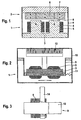
- Fig. 1 shows a highly schematic embodiment of a drive system of the invention Razor in section.
- the drive system of the razor is as Oscillating linear motor formed, the two movable engine components 1 and 2 has, which are arranged at a small distance from each other.
- the first engine component 1 consists of an iron core 3, the two in the direction of the second engine component 2 extending legs 4 has.
- On each leg 4 is a wire wound Coil 5 is arranged, wherein the coils 5 as separate individual coils or as a common coil can be operated.
- the second engine component 2 has three Permanent magnets 6 on, each with antiparallel oriented polarity side by side on a common support plate 7 are arranged, so that in each case one of the magnetic poles for Iron core 3 of the first engine component 1 points out.
- the support plate 7 is as well the iron core 3 made of a ferrous material.
- the two engine components 1 and 2 are tight arranged side by side, so that the permanent magnets 6 from the end face of the respectively adjacent Leg 4 of the iron core 3 each separated only by a small air gap 8 are.
- the width of the air gaps 8 is determined by two leaf springs 9, each are fixed laterally on the iron core 3 and on the support plate 7.
- the leaf springs 9 have the Property that they are both rigid within the plane they build up Behave body and give it to spring resiliently.
- the coils 5 each act as an electromagnet and generate supported by the iron core 3, a magnetic field on the permanent magnets. 6 acts and a relative movement between the coil 5 and the permanent magnet 6 for Episode has.
- the magnetic field generated by the coils 5 can each be reversed, so that the first and second engine components 1 and 2 in to each other in opposite phase vibrations are added.
- both the first engine component 1 and the second engine component 2 moves, d. h., That the linear motor has no stator, with whose help a runner is driven, but two mutually oscillating engine components 1 and 2, driving each other.
- One of these engine components 1 or 2 corresponds to the rotor of a conventional linear motor.
- the other takes over Functions of the stator of a conventional linear motor, but is in contrast to this not static, but also moving.
- the frequency of the oscillatory motion of the two engine components 1 and 2 is set via the control of the coil 5 and in particular adjusted so that it corresponds to the resonant frequency of the vibration system caused by the two engine components 1 and 2 and the leaf springs 9 is formed. Under resonance conditions results in a very robust vibration behavior and it is only one-comparative low energy intake required.
- Fig. 2 shows a highly schematic partial view of the razor according to the invention with the in Fig. 1 illustrated embodiment of the linear motor.
- the view is on the immediate Installation environment of the linear motor in the razor limited.
- the linear motor is suspended over the leaf springs 9 on a housing 10 of the razor, d. H. in the illustrated Embodiment take over the leaf springs 9 in addition to the movable Coupling of the two engine components 1 and 2 with each other the function of the suspension of the linear motor on the housing 10. Details of a possible geometric Design of the leaf springs 9 will be explained with reference to FIG. 3.
- a suspension of the Linear motor by means of the leaf springs 9 offers itself, because in contrast to conventional Linear motors both engine components 1 and 2 move and thus a screw with the housing 10 or other rigid attachment of one of the engine components 1 or 2 is out of the question.
- Through the leaf springs 9 can be a frictionless Suspension can be realized and also the appearance of unwanted vibrations of the housing 10 are largely avoided. So that the linear motor despite this loose suspension assumes a defined rest position and to stabilize the leaf springs 9 is at least one of the leaf springs 9 via an additional spring element 11 with the housing 10th connected.
- a shearing blade 12 is further shown, which at the first Engine component 1 or on the second engine component 2 is mounted.
- shearing blades 12 one being on the first motor component 1 and the other is attached to the second engine component 2.
- the Shearing blade 12 or each of the two shearing blades 12 is driven by the linear motor, so that it performs a reciprocating motion.
- Fig. 3 shows an embodiment of the leaf spring 9 in the installed state in side view.
- the view is chosen so that the two engine components 1 and 2, which are covered by the leaf spring 9, swing perpendicular to the plane of the drawing.
- the leaf spring 9 is cross-shaped in this embodiment and has a relatively wide horizontal bar 13 and a centrally arranged thereto, comparatively narrow vertical beam 14, which are integrally formed with each other.
- the horizontal bar 13 serves to connect the first and second motor components 1 and 2.
- the vertical bar 14 serves to suspend the linear motor on the housing 10 of the razor and, due to its geometry, has a substantially smaller spring constant than the horizontal bar 13.
- Fig. 3 differs slightly from that shown in Fig. 2
- Leaf springs 9 from, as the additional spring element 11 of FIG. 2 in the form of the lower Section of the vertical bar 14 is integrated in the leaf spring 9, d. H. the leaf springs 9 as shown in FIG. 2 do not need this lower portion and thus instead of a cross shape have a T-shape.
- the attachment to the housing 10 takes place in each case at the bottom and at the upper end of the vertical bar 14.
- the central arrangement of the vertical Beam 14 on the horizontal bar 13 and the correspondingly central suspension of the Horizontal bar 13 it is also possible to provide two vertical bars 14, which in the both end portions of the horizontal bar 13 are arranged and a terminal Suspension of the horizontal bar 13 serve on the housing 10.
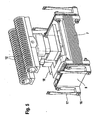
- FIG. 4 shows a perspective partial view of an embodiment of the device according to the invention Razor in a Fig. 2 corresponding section.
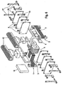
- FIG. 5 again shows the same illustration as Fig. 4, although some covers are removed, so that more details are visible.
- An exploded view associated with FIG. 5 is shown in FIG. 6 displayed.
- Essential for the invention are shown in Figs. 4 to 6 training of the linear motor and its suspension in the razor. The other training, not shown of the razor can be done in a conventional manner.
- the engine components 1 and 2 correspond in shape substantially to the in Fig. 1 illustrated embodiment, wherein the second engine component 2, however has now four permanent magnets 6 instead of three permanent magnets 6.
- a shearing blade 12 is mounted, so that the two shearing blades 12 in phase opposition oscillate to each other.
- the arrangement of the blades 12 on the engine components 1 and 2 takes place crosswise, so that the first of the engine component. 1 driven razor 12 is disposed over the second motor component 2 and the shearing blades 12 driven by the second engine component 2 over the first engine component 1.
- a leveling compound 18 is attached to the rotor 7.
- each through spacers 15 are kept at a distance from each other and clamped together by means of screws 16 and are attached to the two engine components 1 and 2.
- Swinging bridges 17 are provided, which are formed as regions of tapered strip are and are usually made analogous to the leaf springs 9 of a spring steel. At one end of the swing bridges 17 are each together with the leaf springs. 9 screwed to one of the engine components 1 or 2. At the other end are the swinging bridges 17 screwed to the housing 10.
- the two Stack of leaf springs 9 continuously bent elastically so that their narrow sides in each case deflected in opposite directions, with the direction of the deflection reversed periodically.
- Ends of the swinging bridges 17 With the narrow sides of the leaf springs 9 and the attached thereto Ends of the swinging bridges 17 periodically deflected.
- the swing bridges 17 are dimensioned very weak, However, these deflections are hardly transmitted to the housing 10. However, you can the swing bridges 17 in this case, no significant angular momentum or record linear impulse.
- the geometry of the linear motor is therefore to be interpreted so that preferably no resulting angular momentum and as far as possible no resulting linear momentum occurs. This can be achieved by having the center of gravity of the first Engine component 1 including all moving components and the center of mass the second engine component 2 including all moving components move along the same straight line. Furthermore, the linear pulses should be the first and the second engine component 1 and 2 including each moving Components should be the same.
Landscapes
- Engineering & Computer Science (AREA)
- Power Engineering (AREA)
- Dry Shavers And Clippers (AREA)
- Brushes (AREA)
- Apparatuses For Generation Of Mechanical Vibrations (AREA)
- Reciprocating, Oscillating Or Vibrating Motors (AREA)
- Lock And Its Accessories (AREA)
- Transmission Devices (AREA)
Description
- Fig. 1
- ein stark schematisiertes Ausführungsbeispiel eines Antriebssystems des erfindungsgemäßen Rasierers in Schnittdarstellung,
- Fig. 2
- eine stark schematisierte Teilansicht des erfindungsgemäßen Rasierers mit dem in Fig. 1 dargestellten Ausführungsbeispiel des Linearmotors,
- Fig. 3
- ein Ausführungsbeispiel für eine Blattfeder im eingebauten Zustand in Seitenansicht,
- Fig. 4
- eine perspektivische Teilansicht eines Ausführungsbeispiels des erfindungsgemäßen Rasierers, wobei ein Fig. 2 entsprechender Ausschnitt dargestellt ist,
- Fig. 5
- eine Fig. 4 entsprechende Darstellung, wobei allerdings einige Abdeckungen entfernt sind, so daß mehr Einzelheiten sichtbar sind und
- Fig. 6
- das Ausführungsbeispiel aus Fig. 5 in einer perspektivischen Explosionsdarstellung.
Claims (13)
- Elektrisches Kleingerät mit einer Antriebseinrichtung zum Erzeugen einer oszillierenden Bewegung wenigstens einer Arbeitseinheit (12) des elektrischen Kleingeräts, wobei die Antriebseinrichtung eine erste Antriebskomponente (1), eine zweite Antriebskomponente (2) und eine Spule (5) zur Ausbildung eines Magnetfelds aufweist, das von der ersten Antriebskomponente (1) ausgeht und auf die zweite Antriebskomponente (2), die beweglich im elektrischen Kleingerät angeordnet ist, derart einwirkt, daß die zweite Antriebskomponente (2) in eine oszillierende Bewegung versetzt wird, dadurch gekennzeichnet, daß die erste Antriebskomponente (1) zur Ausführung einer zur zweiten Antriebskomponente (2) gegenphasig oszillierenden Bewegung beweglich im elektrischen Kleingerät angeordnet ist, wobei der Luftspalt zwischen zugeordneten Antriebskomponenten im wesentlichen konstant gehalten ist, und daß die Antriebseinrichtung mittels wenigstens eines ersten Federelements (14, 17) am elektrischen Kleingerät befestigt ist.
- Elektrisches Kleingerät nach Anspruch 1, dadurch gekennzeichnet, daß die erste Antriebskomponente (1) und die zweite Antriebskomponente (2) mittels wenigstens eines zweiten Federelements (9, 13) miteinander verbunden sind.
- Elektrisches Kleingerät nach Anspruch 2, dadurch gekennzeichnet, daß die Federkonstante des zweiten Federelements (9, 13) größer ist als die Federkonstante des ersten Federelements (14, 17).
- Elektrisches Kleingerät nach einem der vorhergehenden Ansprüche, dadurch gekennzeichnet, daß das erste Federelement (14, 17) und/oder das zweite Federelement (9, 13) als Blattfeder ausgebildet ist.
- Elektrisches Kleingerät nach einem der Ansprüche 2 bis 4, dadurch gekennzeichnet, daß das erste Federelement (14) und das zweite Federelement (13) als eine integrale Einheit ausgebildet sind.
- Elektrisches Kleingerät nach Anspruch 5, dadurch gekennzeichnet, daß das erste Federelement (14) und das zweite Federelement (13) als eine gemeinsame Blattfeder in Form eines Kreuzes ausgebildet sind.
- Elektrisches Kleingerät nach einem der Ansprüche 2 bis 4, dadurch gekennzeichnet, daß mehrere zweite Federelemente (9) stapelförmig übereinander angeordnet sind.
- Elektrisches Kleingerät nach Anspruch 7, dadurch gekennzeichnet, daß die zweiten Federelemente (9) durch Zwischenstücke (15) auf Abstand zueinander gehalten werden.
- Elektrisches Kleingerät nach einem der vorhergehenden Ansprüche, dadurch gekennzeichnet, daß ein drittes Federelement (11) zur Festlegung einer Ruheposition der Antriebseinrichtung vorgesehen ist.
- Elektrisches Kleingerät nach einem der vorhergehenden Ansprüche, dadurch gekennzeichnet, daß sich die Massenschwerpunkte der ersten Antriebskomponente (1) und der zweiten Antriebskomponente (2) inklusive sich mit der ersten Antriebskomponente (1) oder der zweiten Antriebskomponente (2) mitbewegender Bauteile auf einer gemeinsamen Geraden bewegen.
- Elektrisches Kleingerät nach einem der vorhergehenden Ansprüche, dadurch gekennzeichnet, daß die Impulse der ersten Antriebskomponente (1) und der zweiten Antriebskomponente (2) inklusive sich mit der ersten Antriebskomponente (1) oder der zweiten Antriebskomponente (2) mitbewegender Bauteile entgegengesetzt gleich sind.
- Elektrisches Kleingerät nach einem der vorhergehenden Ansprüche, dadurch gekennzeichnet, daß wenigstens eine der beiden Antriebskomponenten (1, 2) wenigsten einen Dauermagneten (6) aufweist.
- Elektrisches Kleingerät nach einem der vorhergehenden Ansprüche, dadurch gekennzeichnet, daß wenigstens eine der beiden Antriebskomponenten (1, 2) einen Wickelkem (3) aufweist, auf dem die Spule (5) angeordnet ist.
Applications Claiming Priority (3)
| Application Number | Priority Date | Filing Date | Title |
|---|---|---|---|
| DE10242091A DE10242091A1 (de) | 2002-09-11 | 2002-09-11 | Elektrisches Kleingerät mit einer Antriebseinrichtung zur Erzeugung einer oszillierenden Bewegung |
| DE10242091 | 2002-09-11 | ||
| PCT/EP2003/009152 WO2004028759A1 (de) | 2002-09-11 | 2003-08-19 | Elektrisches kleingerät mit einer antriebseinrichtung zur erzeugung einer oszillierenden bewegung |
Publications (2)
| Publication Number | Publication Date |
|---|---|
| EP1539439A1 EP1539439A1 (de) | 2005-06-15 |
| EP1539439B1 true EP1539439B1 (de) | 2005-12-21 |
Family
ID=31969067
Family Applications (1)
| Application Number | Title | Priority Date | Filing Date |
|---|---|---|---|
| EP03798107A Expired - Lifetime EP1539439B1 (de) | 2002-09-11 | 2003-08-19 | Elektrisches kleingerät mit einer antriebseinrichtung zur erzeugung einer oszillierenden bewegung |
Country Status (7)
| Country | Link |
|---|---|
| EP (1) | EP1539439B1 (de) |
| JP (1) | JP4679902B2 (de) |
| CN (1) | CN100346945C (de) |
| AT (1) | ATE313419T1 (de) |
| AU (1) | AU2003258629A1 (de) |
| DE (2) | DE10242091A1 (de) |
| WO (1) | WO2004028759A1 (de) |
Families Citing this family (15)
| Publication number | Priority date | Publication date | Assignee | Title |
|---|---|---|---|---|
| DE102005044176A1 (de) | 2005-09-16 | 2007-03-29 | Braun Gmbh | Haarentfernungsgerät |
| DE102005044175A1 (de) * | 2005-09-16 | 2007-03-29 | Braun Gmbh | Haarentfernungsgerät |
| DE102005060653A1 (de) * | 2005-12-19 | 2007-06-21 | Robert Bosch Gmbh | Vorrichtung zur Detektion eines Objekts |
| DE102006034050A1 (de) * | 2006-07-20 | 2008-01-24 | Braun Gmbh | Elektrischer Rasierapparat |
| FR2971902B1 (fr) | 2011-02-23 | 2013-11-08 | Moving Magnet Tech | Actionneur electromagnetique a densite de force amelioree et application a un rasoir electrique |
| JP6275501B2 (ja) * | 2014-02-07 | 2018-02-07 | マクセルホールディングス株式会社 | 電気かみそり |
| US10792138B2 (en) | 2015-01-28 | 2020-10-06 | Shanghai Shift Electrics Co., Ltd. | Cleaning device |
| CN106324959B (zh) | 2015-07-01 | 2018-08-21 | 中强光电股份有限公司 | 振荡透镜模块及投影装置 |
| JP6765079B2 (ja) * | 2017-04-19 | 2020-10-07 | パナソニックIpマネジメント株式会社 | 振動型リニアアクチュエータ、および、体毛処理機 |
| JP6793366B2 (ja) * | 2017-04-19 | 2020-12-02 | パナソニックIpマネジメント株式会社 | 振動型リニアアクチュエータ、および、切断装置 |
| CN108258874B (zh) | 2017-12-27 | 2019-11-01 | 广州赤力科技有限公司 | 摆动马达及电动装置 |
| WO2021252731A1 (en) | 2020-06-11 | 2021-12-16 | Andis Company | Hair clipper with linear actuator |
| CN112803697B (zh) * | 2021-01-18 | 2022-03-25 | 深圳市泓之发机电有限公司 | 线性驱动组件 |
| CN114123702B (zh) * | 2021-12-16 | 2023-03-21 | 广东辉达电器有限公司 | 一种无刷电磁悬浮振动电机 |
| DE102024106944A1 (de) * | 2024-03-11 | 2025-09-11 | Wahl Gmbh | Magnetisch betriebener Schneidsatz für elektrische Haarschneidemaschinen, elektrische Haarschneidemaschine und Verfahren zum Antreiben eines solchen Schneidsatzes |
Family Cites Families (8)
| Publication number | Priority date | Publication date | Assignee | Title |
|---|---|---|---|---|
| CH265598A (de) * | 1946-01-23 | 1949-12-15 | Odstrcil Borivoj | Trockenrasierapparat. |
| NL136196C (de) * | 1960-09-29 | |||
| GB1028215A (en) * | 1963-02-02 | 1966-05-04 | Morphy Richards Cray Ltd | Improvements relating to vibrator motors for electric dry shavers and other electro-mechanical devices |
| FR2212673B2 (de) * | 1972-12-29 | 1977-02-25 | Crouzet Sa | |
| JP3266757B2 (ja) * | 1995-05-26 | 2002-03-18 | 松下電工株式会社 | 振動型リニアアクチュエータ |
| DE19736776C2 (de) * | 1997-08-23 | 1999-06-02 | Braun Gmbh | Trockenrasierapparat |
| EP1162721B1 (de) * | 2000-06-07 | 2005-12-21 | Matsushita Electric Works, Ltd. | Lineare Schwingungsvorrichtung |
| US6873067B2 (en) * | 2000-09-29 | 2005-03-29 | Matsushita Electric Works, Ltd. | Linear oscillator |
-
2002
- 2002-09-11 DE DE10242091A patent/DE10242091A1/de not_active Withdrawn
-
2003
- 2003-08-19 AU AU2003258629A patent/AU2003258629A1/en not_active Abandoned
- 2003-08-19 DE DE50302024T patent/DE50302024D1/de not_active Expired - Lifetime
- 2003-08-19 AT AT03798107T patent/ATE313419T1/de active
- 2003-08-19 EP EP03798107A patent/EP1539439B1/de not_active Expired - Lifetime
- 2003-08-19 JP JP2004538809A patent/JP4679902B2/ja not_active Expired - Lifetime
- 2003-08-19 CN CNB038216744A patent/CN100346945C/zh not_active Expired - Lifetime
- 2003-08-19 WO PCT/EP2003/009152 patent/WO2004028759A1/de not_active Ceased
Also Published As
| Publication number | Publication date |
|---|---|
| CN1681628A (zh) | 2005-10-12 |
| JP4679902B2 (ja) | 2011-05-11 |
| DE50302024D1 (de) | 2006-01-26 |
| WO2004028759A1 (de) | 2004-04-08 |
| DE10242091A1 (de) | 2004-04-01 |
| CN100346945C (zh) | 2007-11-07 |
| ATE313419T1 (de) | 2006-01-15 |
| AU2003258629A1 (en) | 2004-04-19 |
| JP2005537898A (ja) | 2005-12-15 |
| EP1539439A1 (de) | 2005-06-15 |
Similar Documents
| Publication | Publication Date | Title |
|---|---|---|
| EP1539437B1 (de) | Elektrisches kleingerät mit einer antriebseinrichtung zur erzeugung einer oszillierenden bewegung | |
| EP1509368B1 (de) | Antriebseinrichtung zur erzeugung einer oszillierenden bewegung für ein elektrisches kleingerät | |
| EP1641602B1 (de) | Elektrisches kleingerät mit einem elektromotor zur erzeugung einer oszillierenden bewegung | |
| EP1539439B1 (de) | Elektrisches kleingerät mit einer antriebseinrichtung zur erzeugung einer oszillierenden bewegung | |
| EP2108215B1 (de) | Antriebsvorrichtung zum antreiben eines bürstenelements einer elektrischen zahnbürste | |
| EP1687887B1 (de) | Elektromotor für ein elektrisches kleingerät | |
| DE69317977T2 (de) | Elektromagnetischer betätiger mit zwei beweglichen elementen in gegenphase | |
| DE69819014T2 (de) | Elektromagnetischer antrieb mit zwei gegenphasigen mobilen teilen | |
| EP1108283A1 (de) | Elektromagnetischer aktuator mit schwingendem feder-masse-system | |
| DE102008051126A1 (de) | Elektromagnetischer Erreger und Herstellungsverfahren dafür | |
| EP2043828A1 (de) | Elektrischer rasierapparat | |
| DE10242094B4 (de) | Antriebseinrichtung zum Erzeugen einer oszillierenden Bewegung für ein elektrisches Kleingerät | |
| DE69920116T2 (de) | Elektromagnet-Motor und aktive Schwingungsvorrichtung unter Verwendung eines solchen Motors | |
| DE102005060537A1 (de) | Elektrischer Rasierapparat mit oszillierendem Scherkopf | |
| EP1539438B1 (de) | Antriebseinrichtung zum erzeugen einer oszillierenden bewegung für ein elektrisches kleingerät | |
| DE60317738T2 (de) | Ein oszillierender Linearaktuator | |
| DE60034627T2 (de) | Resonanzvorrichtung wie Schläger oder Krafterzeuger | |
| EP1642380B1 (de) | Verfahren zur steuerung eines elektromotors mit mehreren schwingungsfähigen motorkomponenten | |
| DE8816835U1 (de) | Haushaltsvibrationsgerät, insbesondere Trockenrasiergerät | |
| DE3409182A1 (de) | Magnetisches antriebssystem | |
| DE2336759A1 (de) | Wechselstrom-schwingankermotor, insbesondere fuer trockenrasiergeraete | |
| DE1203510B (de) | Elektromagnetischer Schwingungserreger | |
| DE4117226A1 (de) | Haushaltsvibrationsgeraet mit einem vibrationsteil und einstellbarer eigenfrequenz | |
| DE8407692U1 (de) | Magnetische antriebsvorrichtung |
Legal Events
| Date | Code | Title | Description |
|---|---|---|---|
| PUAI | Public reference made under article 153(3) epc to a published international application that has entered the european phase |
Free format text: ORIGINAL CODE: 0009012 |
|
| 17P | Request for examination filed |
Effective date: 20050211 |
|
| AK | Designated contracting states |
Kind code of ref document: A1 Designated state(s): AT BE BG CH CY CZ DE DK EE ES FI FR GB GR HU IE IT LI LU MC NL PT RO SE SI SK TR |
|
| AX | Request for extension of the european patent |
Extension state: AL LT LV MK |
|
| GRAP | Despatch of communication of intention to grant a patent |
Free format text: ORIGINAL CODE: EPIDOSNIGR1 |
|
| GRAS | Grant fee paid |
Free format text: ORIGINAL CODE: EPIDOSNIGR3 |
|
| GRAA | (expected) grant |
Free format text: ORIGINAL CODE: 0009210 |
|
| AK | Designated contracting states |
Kind code of ref document: B1 Designated state(s): AT BE BG CH CY CZ DE DK EE ES FI FR GB GR HU IE IT LI LU MC NL PT RO SE SI SK TR |
|
| DAX | Request for extension of the european patent (deleted) | ||
| PG25 | Lapsed in a contracting state [announced via postgrant information from national office to epo] |
Ref country code: IT Free format text: LAPSE BECAUSE OF FAILURE TO SUBMIT A TRANSLATION OF THE DESCRIPTION OR TO PAY THE FEE WITHIN THE PRESCRIBED TIME-LIMIT;WARNING: LAPSES OF ITALIAN PATENTS WITH EFFECTIVE DATE BEFORE 2007 MAY HAVE OCCURRED AT ANY TIME BEFORE 2007. THE CORRECT EFFECTIVE DATE MAY BE DIFFERENT FROM THE ONE RECORDED. Effective date: 20051221 Ref country code: FI Free format text: LAPSE BECAUSE OF FAILURE TO SUBMIT A TRANSLATION OF THE DESCRIPTION OR TO PAY THE FEE WITHIN THE PRESCRIBED TIME-LIMIT Effective date: 20051221 Ref country code: RO Free format text: LAPSE BECAUSE OF FAILURE TO SUBMIT A TRANSLATION OF THE DESCRIPTION OR TO PAY THE FEE WITHIN THE PRESCRIBED TIME-LIMIT Effective date: 20051221 Ref country code: SI Free format text: LAPSE BECAUSE OF FAILURE TO SUBMIT A TRANSLATION OF THE DESCRIPTION OR TO PAY THE FEE WITHIN THE PRESCRIBED TIME-LIMIT Effective date: 20051221 Ref country code: SK Free format text: LAPSE BECAUSE OF FAILURE TO SUBMIT A TRANSLATION OF THE DESCRIPTION OR TO PAY THE FEE WITHIN THE PRESCRIBED TIME-LIMIT Effective date: 20051221 Ref country code: IE Free format text: LAPSE BECAUSE OF FAILURE TO SUBMIT A TRANSLATION OF THE DESCRIPTION OR TO PAY THE FEE WITHIN THE PRESCRIBED TIME-LIMIT Effective date: 20051221 Ref country code: CZ Free format text: LAPSE BECAUSE OF FAILURE TO SUBMIT A TRANSLATION OF THE DESCRIPTION OR TO PAY THE FEE WITHIN THE PRESCRIBED TIME-LIMIT Effective date: 20051221 Ref country code: NL Free format text: LAPSE BECAUSE OF FAILURE TO SUBMIT A TRANSLATION OF THE DESCRIPTION OR TO PAY THE FEE WITHIN THE PRESCRIBED TIME-LIMIT Effective date: 20051221 |
|
| REG | Reference to a national code |
Ref country code: GB Ref legal event code: FG4D Free format text: NOT ENGLISH |
|
| REG | Reference to a national code |
Ref country code: CH Ref legal event code: EP |
|
| GBT | Gb: translation of ep patent filed (gb section 77(6)(a)/1977) |
Effective date: 20051221 |
|
| REG | Reference to a national code |
Ref country code: IE Ref legal event code: FG4D Free format text: LANGUAGE OF EP DOCUMENT: GERMAN |
|
| REF | Corresponds to: |
Ref document number: 50302024 Country of ref document: DE Date of ref document: 20060126 Kind code of ref document: P |
|
| PG25 | Lapsed in a contracting state [announced via postgrant information from national office to epo] |
Ref country code: SE Free format text: LAPSE BECAUSE OF FAILURE TO SUBMIT A TRANSLATION OF THE DESCRIPTION OR TO PAY THE FEE WITHIN THE PRESCRIBED TIME-LIMIT Effective date: 20060321 Ref country code: BG Free format text: LAPSE BECAUSE OF FAILURE TO SUBMIT A TRANSLATION OF THE DESCRIPTION OR TO PAY THE FEE WITHIN THE PRESCRIBED TIME-LIMIT Effective date: 20060321 Ref country code: DK Free format text: LAPSE BECAUSE OF FAILURE TO SUBMIT A TRANSLATION OF THE DESCRIPTION OR TO PAY THE FEE WITHIN THE PRESCRIBED TIME-LIMIT Effective date: 20060321 Ref country code: GR Free format text: LAPSE BECAUSE OF FAILURE TO SUBMIT A TRANSLATION OF THE DESCRIPTION OR TO PAY THE FEE WITHIN THE PRESCRIBED TIME-LIMIT Effective date: 20060321 |
|
| PG25 | Lapsed in a contracting state [announced via postgrant information from national office to epo] |
Ref country code: ES Free format text: LAPSE BECAUSE OF FAILURE TO SUBMIT A TRANSLATION OF THE DESCRIPTION OR TO PAY THE FEE WITHIN THE PRESCRIBED TIME-LIMIT Effective date: 20060401 |
|
| PG25 | Lapsed in a contracting state [announced via postgrant information from national office to epo] |
Ref country code: PT Free format text: LAPSE BECAUSE OF FAILURE TO SUBMIT A TRANSLATION OF THE DESCRIPTION OR TO PAY THE FEE WITHIN THE PRESCRIBED TIME-LIMIT Effective date: 20060522 |
|
| NLV1 | Nl: lapsed or annulled due to failure to fulfill the requirements of art. 29p and 29m of the patents act | ||
| PG25 | Lapsed in a contracting state [announced via postgrant information from national office to epo] |
Ref country code: HU Free format text: LAPSE BECAUSE OF FAILURE TO SUBMIT A TRANSLATION OF THE DESCRIPTION OR TO PAY THE FEE WITHIN THE PRESCRIBED TIME-LIMIT Effective date: 20060622 |
|
| REG | Reference to a national code |
Ref country code: IE Ref legal event code: FD4D |
|
| ET | Fr: translation filed | ||
| PG25 | Lapsed in a contracting state [announced via postgrant information from national office to epo] |
Ref country code: MC Free format text: LAPSE BECAUSE OF NON-PAYMENT OF DUE FEES Effective date: 20060831 |
|
| PLBE | No opposition filed within time limit |
Free format text: ORIGINAL CODE: 0009261 |
|
| STAA | Information on the status of an ep patent application or granted ep patent |
Free format text: STATUS: NO OPPOSITION FILED WITHIN TIME LIMIT |
|
| 26N | No opposition filed |
Effective date: 20060922 |
|
| REG | Reference to a national code |
Ref country code: CH Ref legal event code: PL |
|
| PG25 | Lapsed in a contracting state [announced via postgrant information from national office to epo] |
Ref country code: CH Free format text: LAPSE BECAUSE OF NON-PAYMENT OF DUE FEES Effective date: 20070831 Ref country code: LI Free format text: LAPSE BECAUSE OF NON-PAYMENT OF DUE FEES Effective date: 20070831 |
|
| PG25 | Lapsed in a contracting state [announced via postgrant information from national office to epo] |
Ref country code: EE Free format text: LAPSE BECAUSE OF FAILURE TO SUBMIT A TRANSLATION OF THE DESCRIPTION OR TO PAY THE FEE WITHIN THE PRESCRIBED TIME-LIMIT Effective date: 20051221 |
|
| PG25 | Lapsed in a contracting state [announced via postgrant information from national office to epo] |
Ref country code: LU Free format text: LAPSE BECAUSE OF NON-PAYMENT OF DUE FEES Effective date: 20060819 Ref country code: TR Free format text: LAPSE BECAUSE OF FAILURE TO SUBMIT A TRANSLATION OF THE DESCRIPTION OR TO PAY THE FEE WITHIN THE PRESCRIBED TIME-LIMIT Effective date: 20051221 |
|
| PG25 | Lapsed in a contracting state [announced via postgrant information from national office to epo] |
Ref country code: CY Free format text: LAPSE BECAUSE OF FAILURE TO SUBMIT A TRANSLATION OF THE DESCRIPTION OR TO PAY THE FEE WITHIN THE PRESCRIBED TIME-LIMIT Effective date: 20051221 |
|
| REG | Reference to a national code |
Ref country code: FR Ref legal event code: PLFP Year of fee payment: 14 |
|
| REG | Reference to a national code |
Ref country code: FR Ref legal event code: PLFP Year of fee payment: 15 |
|
| REG | Reference to a national code |
Ref country code: FR Ref legal event code: PLFP Year of fee payment: 16 |
|
| PGFP | Annual fee paid to national office [announced via postgrant information from national office to epo] |
Ref country code: SK Payment date: 20180806 Year of fee payment: 16 Ref country code: AT Payment date: 20180725 Year of fee payment: 16 |
|
| REG | Reference to a national code |
Ref country code: AT Ref legal event code: MM01 Ref document number: 313419 Country of ref document: AT Kind code of ref document: T Effective date: 20190819 |
|
| PG25 | Lapsed in a contracting state [announced via postgrant information from national office to epo] |
Ref country code: AT Free format text: LAPSE BECAUSE OF NON-PAYMENT OF DUE FEES Effective date: 20190819 |
|
| REG | Reference to a national code |
Ref country code: BE Ref legal event code: MM Effective date: 20190831 |
|
| PG25 | Lapsed in a contracting state [announced via postgrant information from national office to epo] |
Ref country code: BE Free format text: LAPSE BECAUSE OF NON-PAYMENT OF DUE FEES Effective date: 20190831 |
|
| PGFP | Annual fee paid to national office [announced via postgrant information from national office to epo] |
Ref country code: GB Payment date: 20220630 Year of fee payment: 20 |
|
| PGFP | Annual fee paid to national office [announced via postgrant information from national office to epo] |
Ref country code: DE Payment date: 20220705 Year of fee payment: 20 |
|
| PGFP | Annual fee paid to national office [announced via postgrant information from national office to epo] |
Ref country code: FR Payment date: 20220709 Year of fee payment: 20 |
|
| P01 | Opt-out of the competence of the unified patent court (upc) registered |
Effective date: 20230430 |
|
| REG | Reference to a national code |
Ref country code: DE Ref legal event code: R071 Ref document number: 50302024 Country of ref document: DE |
|
| REG | Reference to a national code |
Ref country code: GB Ref legal event code: PE20 Expiry date: 20230818 |
|
| PG25 | Lapsed in a contracting state [announced via postgrant information from national office to epo] |
Ref country code: GB Free format text: LAPSE BECAUSE OF EXPIRATION OF PROTECTION Effective date: 20230818 |