EP1538784B1 - Convertisseur pour des systèmes de bus d'installation - Google Patents
Convertisseur pour des systèmes de bus d'installation Download PDFInfo
- Publication number
- EP1538784B1 EP1538784B1 EP04028504A EP04028504A EP1538784B1 EP 1538784 B1 EP1538784 B1 EP 1538784B1 EP 04028504 A EP04028504 A EP 04028504A EP 04028504 A EP04028504 A EP 04028504A EP 1538784 B1 EP1538784 B1 EP 1538784B1
- Authority
- EP
- European Patent Office
- Prior art keywords
- bus
- wire
- stage
- converter
- bus system
- Prior art date
- Legal status (The legal status is an assumption and is not a legal conclusion. Google has not performed a legal analysis and makes no representation as to the accuracy of the status listed.)
- Active
Links
Images
Classifications
-
- H—ELECTRICITY
- H04—ELECTRIC COMMUNICATION TECHNIQUE
- H04L—TRANSMISSION OF DIGITAL INFORMATION, e.g. TELEGRAPHIC COMMUNICATION
- H04L12/00—Data switching networks
- H04L12/28—Data switching networks characterised by path configuration, e.g. LAN [Local Area Networks] or WAN [Wide Area Networks]
- H04L12/46—Interconnection of networks
- H04L12/4604—LAN interconnection over a backbone network, e.g. Internet, Frame Relay
- H04L12/462—LAN interconnection over a bridge based backbone
- H04L12/4625—Single bridge functionality, e.g. connection of two networks over a single bridge
-
- H—ELECTRICITY
- H04—ELECTRIC COMMUNICATION TECHNIQUE
- H04L—TRANSMISSION OF DIGITAL INFORMATION, e.g. TELEGRAPHIC COMMUNICATION
- H04L12/00—Data switching networks
- H04L12/28—Data switching networks characterised by path configuration, e.g. LAN [Local Area Networks] or WAN [Wide Area Networks]
- H04L12/40—Bus networks
- H04L12/40006—Architecture of a communication node
- H04L12/40045—Details regarding the feeding of energy to the node from the bus
-
- H—ELECTRICITY
- H04—ELECTRIC COMMUNICATION TECHNIQUE
- H04L—TRANSMISSION OF DIGITAL INFORMATION, e.g. TELEGRAPHIC COMMUNICATION
- H04L12/00—Data switching networks
- H04L12/28—Data switching networks characterised by path configuration, e.g. LAN [Local Area Networks] or WAN [Wide Area Networks]
- H04L12/40—Bus networks
- H04L2012/4026—Bus for use in automation systems
Definitions
- the invention relates to a converter for installation bus systems for enabling communication between a two-wire and a four-wire bus system, which are operated in the same bus protocol, each bus system comprising bus coupling, each having a telegram unit for generating bus telegrams from external signals, or vice versa , and a bus connection unit with transmission stage and receive stage for bus telegrams included.
- the information and the supply current are routed via separate wire pairs.
- the effort for the separation of supply current and information is eliminated, making the bus couplers are simple and inexpensive.
- Installation bus systems are permanently installed in a building regardless of the mains power supply. They are used to store data, information, commands and the like. transferred to. At the connection points there are bus couplers to which external devices are connected. The external devices are often sensors, actuators, e.g. Actuators, or manual input devices, such as switches or dimmers. In a building it happens that two-wire lines are available for certain routes and four-wire lines for other routes. Normally, when these installed lines are interconnected to form a data bus, a unitary two-wire bus system would have to be formed. This requires a greater effort in the bus couplers and does not use the existing four-wire lines.
- the Busankoppler contain a telegram unit for the generation or evaluation of bus telegrams and a bus connection unit with transmission level and receiving level for the bus telegrams.
- the telegram unit forms the information part and the bus connection unit forms the physical bus connection for connecting the information part to the data bus.
- EP-A-0566935 describes an interface module for connecting two bus segments.
- the interface component is used for a change from bidirectional operation of a two-wire bus line to unidirectional operation of two two-wire bus lines, ie a unidirectional four-wire operation. In unidirectional operation, significantly greater distances can be transmitted than in bidirectional operation.
- the interface component each contains a bus driver with a transmitter and a receiver. It causes an amplification of the incoming signals for the purpose of forwarding. In the interface component, the receiver of one two-wire line is coupled to the transmitter of the other two-wire line, and vice versa. In this way, a bidirectional operation with loop gain occurs. The power supply also takes place via the bus system.
- the invention has for its object to provide a converter for installation bus systems, with which a four-wire bus system and a two-wire bus system, which are operated in the same bus protocol, can be combined with each other in a simple manner.
- the converter according to the invention is characterized by the claim 1. It consists of a device which - preferably in the same housing - each contains a Busan gleichiser each of the two bus types, but without telegram unit.
- the bus connection units are combined in such a way that the reception stage of each of the two bus connection units is coupled to the transmission stage of the other bus connection unit.
- a converter is assembled from standardized bus connection units of the two systems, which makes it possible to connect the two data buses, namely a two-wire bus and a four-wire bus, whereby each bus is operated in such a way that its advantages are utilized.
- the four-wire bus can thus be equipped with simple and inexpensive bus couplers, while the two-wire bus requires more complex Busankoppler with DC decoupling.
- a manufacturer that supplies bus couplers as standard for each of the two bus systems can easily assemble the converter according to the invention from components of its production program without the need for new circuits and devices.
- a further advantage is that the telegram units of the bus coupling units of both systems, which form the information technology part, can generally be of the same type.
- the same microcontroller can be used, which is tuned to the common bus protocol.
- the converter according to the invention effects a bidirectional conversion between a four-wire bus system and a two-wire bus system.
- the power of the components of the converter can be done either via the two-wire bus system or via the four-wire bus system.
- a supply - via the four-wire bus system has the advantage that the supply voltage is already available on the lines and no decoupling required.
- a galvanic isolation stage can be provided between the two bus connection units in the converter in order to avoid undesired additional couplings and to prevent interference signals from being transmitted via the converter.
- Such galvanic coupling is preferably carried out via optocouplers or inductive transformers.
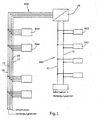
- FIG. 1 shows a two-wire bus system BS2 is shown, which consists of the two wires 11,12, which are connected to a power supply.
- bus coupling units BA2 With the wires 11,12 bus coupling units BA2 are connected, which are also designed two-wire.
- a bus coupler BA2 serves to connect an external device (not shown) to the data bus so that this device receives data or other signals from the bus and / or supplies to the bus.
- the power supply serves to supply all bus coupling units BA2 of the two-wire bus system via the wires 11,12.
- the supply current is superimposed with the pulses of the data telegrams.
- the bus coupling units BA2 can exchange data telegrams with each other.
- a center is not present in this embodiment.
- the four-wire bus system BS4 has four wires 14,15,16,17, of which the wires 14 and 15 conduct the supply current, while the wires 16,17 transmit the information.
- Four-wire bus coupling units BA4 are also connected to the data bus BS4.
- the bus coupling units BA2 and BA4 are part of the bus installation. External devices can be connected to the bus couplers.
- the two bus systems BS2 and BS4 are interconnected by a converter 20, which will be explained in detail.
- a bus coupling unit BA2 can communicate directly with a bus coupling unit BA4.
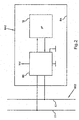
- FIG. 2 shows the structure of a bus coupler BA2 of the two-wire bus system.
- the bus coupling unit BA2 contains a telegram unit TE and a bus connection unit BE.
- the telegram unit TE contains a microprocessor. It is able to generate data telegrams in accordance with the standardized bus protocol on the basis of externally supplied signals and to evaluate such data telegrams that have been received.
- the telegram unit TE forms the information technology part of the bus coupler BA.
- the bus connection unit BE serves for the physical connection to the wires 11, 12 and the preparation of the impulses.
- the telegram unit TE and the bus connection unit BE are interconnected by a data reception line and a data transmission line.
- a bus coupling unit BA4 of the four-wire bus system is not specifically shown.
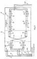
- FIG. 3 shows the converter 20.
- this contains a bus connection unit BE4 of the four-wire bus system and a bus connection unit BE2 of the two-wire bus system.
- the power supply of the converter 20 via the power supply wires 14,15 of the bus system BS4.
- the wires 16, 17 of the four-wire bus system are connected to the output of a transmitting stage 26 and to the input of a receiving stage 27 of the bus connecting unit BE4.
- the input of the receiving stage and the output of the transmitting stage are symmetrical.
- the bus connection unit BE2 contains a transmission stage 30 whose input is coupled to the output of the reception stage 27.
- the output of the transmission stage 30 is connected via a current limiting circuit 31 to the data bus BS2.
- the bus connection unit BE2 also contains a reception stage 32 comprising a level adjustment stage 33 and a pulse regeneration stage 34. Between the reception stage 32 and the data bus BS2 a DC decoupling 35 is connected, which keeps the power supply of the data bus from the reception stage 32.
- the receiving stage 32 of the bus connection unit BE2 is coupled to the transmission stage 26 of the bus connection unit BE4.
- a galvanic isolation stage 42 and 43 is provided for potential separation.
- This isolator consists of an optocoupler or an inductive transformer.
- Bus telegrams which are transmitted on the four-wire bus system BS4 are transmitted by the converter 20 via the receiving stage 27 and the transmission stage 30 to the bus system BS2.
- Information that is generated on the bus system BS2 are transmitted via the receiving stage 32 and the transmission stage 26 from the converter 20 to the bus system BS4.
Landscapes
- Engineering & Computer Science (AREA)
- Computer Networks & Wireless Communication (AREA)
- Signal Processing (AREA)
- Small-Scale Networks (AREA)
- Cable Transmission Systems, Equalization Of Radio And Reduction Of Echo (AREA)
- Input Circuits Of Receivers And Coupling Of Receivers And Audio Equipment (AREA)
Claims (5)
- Convertisseur pour des systèmes de bus d'installation pour permettre une communication entre un système de bus à deux fils (BS2), dans lequel le courant d'alimentation et l'information sont transmis sur la même paire de conducteurs et un système de bus à quatre fils (BS4), dans lequel des informations et le courant d'alimentation sont conduits par l'intermédiaire de paires de conducteurs séparées (16, 17 ; 14, 15), le système de bus à deux fils et le système de bus à quatre fils étant exploités selon le même protocole de bus et chaque système de bus comportant des coupleurs de bus (BA2, BA4) comprenant chacun une unité de télégrammes (TE) pour créer des télégrammes de bus à partir de signaux externes ou inversement et une unité de branchement de bus (BE), avec des étages émetteurs et des étages récepteurs pour des télégrammes de bus,
caractérisé en ce que des unités de branchement de bus (BE2, BE4) des deux systèmes de bus sont rassemblées sans unité de télégramme respectives (TE) dans un appareil (25) de façon telle, que les étages récepteurs (27, 32) de chacune des deux unités de branchement de bus (BE2, BE4) soient accouplés avec l'étage émetteur (26, 30) de l'autre unité de branchement de bus et en ce que l'unité de branchement de bus (BE2) du système de bus à deux fils, contenue dans l'appareil (25), comprend un désaccouplement DC (35). - Convertisseur selon la revendication 1, caractérisé en ce que l'accouplement entre l'étage récepteur et l'étage émetteur est assuré par un étage de séparation galvanique (42, 43).
- Convertisseur selon la revendication 2, caractérisé en ce que l'étage de séparation comporte un optocoupleur ou un transmetteur inductif.
- Convertisseur selon l'une quelconque des revendications 1 à 3, caractérisé en ce que l'alimentation en courant électrique de l'appareil (25) est assurée via le bloc d'alimentation du système de bus à quatre fils (BS4)
- Convertisseur selon l'une quelconque des revendications 1 à 4, caractérisé en ce que l'alimentation en courant électrique de l'appareil (25) est assurée via le bloc d'alimentation du système de bus à deux fils (BS2).
Applications Claiming Priority (2)
| Application Number | Priority Date | Filing Date | Title |
|---|---|---|---|
| DE20318766U | 2003-12-04 | ||
| DE20318766U DE20318766U1 (de) | 2003-12-04 | 2003-12-04 | Umsetzer für Installations-Bussysteme |
Publications (2)
| Publication Number | Publication Date |
|---|---|
| EP1538784A1 EP1538784A1 (fr) | 2005-06-08 |
| EP1538784B1 true EP1538784B1 (fr) | 2006-10-18 |
Family
ID=34442549
Family Applications (1)
| Application Number | Title | Priority Date | Filing Date |
|---|---|---|---|
| EP04028504A Active EP1538784B1 (fr) | 2003-12-04 | 2004-12-02 | Convertisseur pour des systèmes de bus d'installation |
Country Status (4)
| Country | Link |
|---|---|
| EP (1) | EP1538784B1 (fr) |
| AT (1) | ATE343280T1 (fr) |
| DE (2) | DE20318766U1 (fr) |
| ES (1) | ES2274373T3 (fr) |
Families Citing this family (3)
| Publication number | Priority date | Publication date | Assignee | Title |
|---|---|---|---|---|
| DE102006035046B4 (de) * | 2006-07-28 | 2013-05-29 | Insta Elektro Gmbh | Elektrisches/elektronisches Zentralgerät |
| DE102009005431A1 (de) * | 2009-01-19 | 2010-07-22 | Wilo Se | Buskoppler mit Netzteil |
| DE102009014709A1 (de) * | 2009-03-27 | 2010-10-07 | Festool Gmbh | Steuerungseinrichtung für eine portable elektrische Maschine mit einem Kommunikationsbus und Maschine |
Family Cites Families (9)
| Publication number | Priority date | Publication date | Assignee | Title |
|---|---|---|---|---|
| DE3733467A1 (de) * | 1987-09-30 | 1989-04-20 | Siemens Ag | Schaltungsanordnung zur durchschaltung von standverbindungen in kommunikationsnetzen |
| DE4210023A1 (de) * | 1992-03-27 | 1993-09-30 | Sel Alcatel Ag | Digitales Nachrichtenübertragungssystem mit elektrischen symmetrischen Zweidraht-Leitungen unter Verwendung von Phantomkreisen |
| DE4213569C2 (de) * | 1992-04-24 | 1997-01-30 | Siemens Ag | Schnittstellenbaustein zum Verbinden zweier Bussegmente |
| DE9401402U1 (de) * | 1993-03-26 | 1994-03-31 | Siemens Ag | Anschlußadapter für netzgespeiste und busgesteuerte Geräte |
| FR2720576B1 (fr) * | 1994-05-24 | 1996-06-21 | Sgs Thomson Microelectronics | Interface compatible pour installation de commande d'appareils domestiques industriels et professionnels. |
| DE19622366B4 (de) * | 1996-06-04 | 2006-01-26 | Deutsche Telekom Ag | ISDN-Anschlußsystem |
| DE29616064U1 (de) * | 1996-09-14 | 1996-12-05 | Insta Elektro Gmbh & Co Kg | Elektronische Baugruppen zur Erstellung einer Datenkopplung von geringem Volumen für die Übertragung von Daten in der Gebäudesystemtechnik |
| DE29701136U1 (de) * | 1997-01-23 | 1997-06-12 | Insta Elektro Gmbh & Co Kg | Busankoppler |
| DE10205797A1 (de) * | 2002-02-13 | 2003-09-04 | Merten Gmbh & Co Kg | Lokales integriertes Daten- und Telefonnetz |
-
2003
- 2003-12-04 DE DE20318766U patent/DE20318766U1/de not_active Expired - Lifetime
-
2004
- 2004-12-02 AT AT04028504T patent/ATE343280T1/de active
- 2004-12-02 DE DE502004001788T patent/DE502004001788D1/de active Active
- 2004-12-02 EP EP04028504A patent/EP1538784B1/fr active Active
- 2004-12-02 ES ES04028504T patent/ES2274373T3/es active Active
Also Published As
| Publication number | Publication date |
|---|---|
| DE502004001788D1 (de) | 2006-11-30 |
| ATE343280T1 (de) | 2006-11-15 |
| ES2274373T3 (es) | 2007-05-16 |
| DE20318766U1 (de) | 2005-04-21 |
| EP1538784A1 (fr) | 2005-06-08 |
Similar Documents
| Publication | Publication Date | Title |
|---|---|---|
| EP0344609B1 (fr) | Système de transmission numérique pour installations domestiques | |
| DE69719631T2 (de) | Fernspeisungssystem für Netzwerkelemente | |
| EP2823602B1 (fr) | Dispositif de communication par bus | |
| EP0809222A1 (fr) | Appareil de transfert de données dans des systèmes de commande de processus | |
| DE102017213365B4 (de) | Kommunikationsvorrichtung, System und Verfahren | |
| DE2826017A1 (de) | Datenfernverarbeitungsgeraet | |
| EP1538784B1 (fr) | Convertisseur pour des systèmes de bus d'installation | |
| EP1410577B1 (fr) | Elements reseau destines a un reseau optique ayant une fonction de securite, en particulier a un reseau optique a topologie annulaire | |
| EP1759252B1 (fr) | Réseau d'interfaces actionneurs-capteurs pour grandes distances | |
| DE19916894A1 (de) | Bussystem | |
| DE19710137A1 (de) | Verfahren und Vorrichtung zur Erweiterung der räumlichen Ausdehnung bei Sensor-Aktuator-Bussystemen | |
| EP1690390B1 (fr) | Procede de transmission de donnees via un bus de donnees, et systeme et passerelle permettant la mise en oeuvre dudit procede | |
| EP0419711B1 (fr) | Module d'interface pour couplage de signaux modulés | |
| EP3632054B1 (fr) | Determination de noeuds d'un bus de données local | |
| DE102004032839B3 (de) | ASI-System zum Anschluß mehrerer Sensoren und/oder Aktuatoren an eine Steuerung | |
| DE3420795C2 (de) | Verfahren zur Übertragung von digitalen und analogen Signalen zwischen einer Zentrale und mehreren Unterstationen | |
| DE4232922C2 (de) | Anordnung zur Datenübertragung in Prozeßleitsystemen | |
| DE102019200907A1 (de) | Teilnehmerstation für ein Bussystem und Verfahren zur Datenübertragung in einem Bussystem | |
| EP1548991B1 (fr) | Couplage de bus transformateur | |
| DE10101196A1 (de) | Interfaceschaltung und Verfahren für Digitalsignale | |
| DE4412921C2 (de) | Verfahren und Schaltungsanordnung zur gleichzeitigen Übertragung von Daten und Hilfsenergie | |
| DE10155562B4 (de) | Vorrichtung zur Signalweiterleitung | |
| DE102011115431B4 (de) | Feldbusnetzwerkadapter und Feldbusnetzwerkteilnehmer mit Feldbusanschlüssen | |
| DE102005035656A1 (de) | ASK-Kommunikationsvorrichtung | |
| EP1162787B1 (fr) | Dispositif pour connecter des appareils à un réseau de données |
Legal Events
| Date | Code | Title | Description |
|---|---|---|---|
| PUAI | Public reference made under article 153(3) epc to a published international application that has entered the european phase |
Free format text: ORIGINAL CODE: 0009012 |
|
| AK | Designated contracting states |
Kind code of ref document: A1 Designated state(s): AT BE BG CH CY CZ DE DK EE ES FI FR GB GR HU IE IS IT LI LT LU MC NL PL PT RO SE SI SK TR |
|
| AX | Request for extension of the european patent |
Extension state: AL BA HR LV MK YU |
|
| 17P | Request for examination filed |
Effective date: 20050914 |
|
| AKX | Designation fees paid |
Designated state(s): AT BE BG CH CY CZ DE DK EE ES FI FR GB GR HU IE IS IT LI LT LU MC NL PL PT RO SE SI SK TR |
|
| GRAP | Despatch of communication of intention to grant a patent |
Free format text: ORIGINAL CODE: EPIDOSNIGR1 |
|
| GRAS | Grant fee paid |
Free format text: ORIGINAL CODE: EPIDOSNIGR3 |
|
| GRAA | (expected) grant |
Free format text: ORIGINAL CODE: 0009210 |
|
| AK | Designated contracting states |
Kind code of ref document: B1 Designated state(s): AT BE BG CH CY CZ DE DK EE ES FI FR GB GR HU IE IS IT LI LT LU MC NL PL PT RO SE SI SK TR |
|
| PG25 | Lapsed in a contracting state [announced via postgrant information from national office to epo] |
Ref country code: SK Free format text: LAPSE BECAUSE OF FAILURE TO SUBMIT A TRANSLATION OF THE DESCRIPTION OR TO PAY THE FEE WITHIN THE PRESCRIBED TIME-LIMIT Effective date: 20061018 Ref country code: IT Free format text: LAPSE BECAUSE OF FAILURE TO SUBMIT A TRANSLATION OF THE DESCRIPTION OR TO PAY THE FEE WITHIN THE PRESCRIBED TIME-LIMIT;WARNING: LAPSES OF ITALIAN PATENTS WITH EFFECTIVE DATE BEFORE 2007 MAY HAVE OCCURRED AT ANY TIME BEFORE 2007. THE CORRECT EFFECTIVE DATE MAY BE DIFFERENT FROM THE ONE RECORDED. Effective date: 20061018 Ref country code: PL Free format text: LAPSE BECAUSE OF FAILURE TO SUBMIT A TRANSLATION OF THE DESCRIPTION OR TO PAY THE FEE WITHIN THE PRESCRIBED TIME-LIMIT Effective date: 20061018 Ref country code: FI Free format text: LAPSE BECAUSE OF FAILURE TO SUBMIT A TRANSLATION OF THE DESCRIPTION OR TO PAY THE FEE WITHIN THE PRESCRIBED TIME-LIMIT Effective date: 20061018 Ref country code: IE Free format text: LAPSE BECAUSE OF FAILURE TO SUBMIT A TRANSLATION OF THE DESCRIPTION OR TO PAY THE FEE WITHIN THE PRESCRIBED TIME-LIMIT Effective date: 20061018 Ref country code: CZ Free format text: LAPSE BECAUSE OF FAILURE TO SUBMIT A TRANSLATION OF THE DESCRIPTION OR TO PAY THE FEE WITHIN THE PRESCRIBED TIME-LIMIT Effective date: 20061018 Ref country code: SI Free format text: LAPSE BECAUSE OF FAILURE TO SUBMIT A TRANSLATION OF THE DESCRIPTION OR TO PAY THE FEE WITHIN THE PRESCRIBED TIME-LIMIT Effective date: 20061018 Ref country code: RO Free format text: LAPSE BECAUSE OF FAILURE TO SUBMIT A TRANSLATION OF THE DESCRIPTION OR TO PAY THE FEE WITHIN THE PRESCRIBED TIME-LIMIT Effective date: 20061018 Ref country code: LT Free format text: LAPSE BECAUSE OF FAILURE TO SUBMIT A TRANSLATION OF THE DESCRIPTION OR TO PAY THE FEE WITHIN THE PRESCRIBED TIME-LIMIT Effective date: 20061018 |
|
| REG | Reference to a national code |
Ref country code: GB Ref legal event code: FG4D Free format text: NOT ENGLISH |
|
| REG | Reference to a national code |
Ref country code: CH Ref legal event code: EP Ref country code: IE Ref legal event code: FG4D Free format text: LANGUAGE OF EP DOCUMENT: GERMAN |
|
| REF | Corresponds to: |
Ref document number: 502004001788 Country of ref document: DE Date of ref document: 20061130 Kind code of ref document: P |
|
| PG25 | Lapsed in a contracting state [announced via postgrant information from national office to epo] |
Ref country code: BE Free format text: LAPSE BECAUSE OF NON-PAYMENT OF DUE FEES Effective date: 20061231 Ref country code: MC Free format text: LAPSE BECAUSE OF NON-PAYMENT OF DUE FEES Effective date: 20061231 |
|
| PG25 | Lapsed in a contracting state [announced via postgrant information from national office to epo] |
Ref country code: BG Free format text: LAPSE BECAUSE OF FAILURE TO SUBMIT A TRANSLATION OF THE DESCRIPTION OR TO PAY THE FEE WITHIN THE PRESCRIBED TIME-LIMIT Effective date: 20070118 Ref country code: SE Free format text: LAPSE BECAUSE OF FAILURE TO SUBMIT A TRANSLATION OF THE DESCRIPTION OR TO PAY THE FEE WITHIN THE PRESCRIBED TIME-LIMIT Effective date: 20070118 Ref country code: DK Free format text: LAPSE BECAUSE OF FAILURE TO SUBMIT A TRANSLATION OF THE DESCRIPTION OR TO PAY THE FEE WITHIN THE PRESCRIBED TIME-LIMIT Effective date: 20070118 |
|
| PG25 | Lapsed in a contracting state [announced via postgrant information from national office to epo] |
Ref country code: IS Free format text: LAPSE BECAUSE OF FAILURE TO SUBMIT A TRANSLATION OF THE DESCRIPTION OR TO PAY THE FEE WITHIN THE PRESCRIBED TIME-LIMIT Effective date: 20070218 |
|
| PG25 | Lapsed in a contracting state [announced via postgrant information from national office to epo] |
Ref country code: PT Free format text: LAPSE BECAUSE OF FAILURE TO SUBMIT A TRANSLATION OF THE DESCRIPTION OR TO PAY THE FEE WITHIN THE PRESCRIBED TIME-LIMIT Effective date: 20070319 |
|
| GBV | Gb: ep patent (uk) treated as always having been void in accordance with gb section 77(7)/1977 [no translation filed] |
Effective date: 20061018 |
|
| REG | Reference to a national code |
Ref country code: ES Ref legal event code: FG2A Ref document number: 2274373 Country of ref document: ES Kind code of ref document: T3 Ref country code: IE Ref legal event code: FD4D |
|
| ET | Fr: translation filed | ||
| PLBE | No opposition filed within time limit |
Free format text: ORIGINAL CODE: 0009261 |
|
| STAA | Information on the status of an ep patent application or granted ep patent |
Free format text: STATUS: NO OPPOSITION FILED WITHIN TIME LIMIT |
|
| 26N | No opposition filed |
Effective date: 20070719 |
|
| PG25 | Lapsed in a contracting state [announced via postgrant information from national office to epo] |
Ref country code: GB Free format text: LAPSE BECAUSE OF FAILURE TO SUBMIT A TRANSLATION OF THE DESCRIPTION OR TO PAY THE FEE WITHIN THE PRESCRIBED TIME-LIMIT Effective date: 20061018 |
|
| BERE | Be: lapsed |
Owner name: MERTEN G.M.B.H. & CO. KG Effective date: 20061231 |
|
| PG25 | Lapsed in a contracting state [announced via postgrant information from national office to epo] |
Ref country code: GR Free format text: LAPSE BECAUSE OF FAILURE TO SUBMIT A TRANSLATION OF THE DESCRIPTION OR TO PAY THE FEE WITHIN THE PRESCRIBED TIME-LIMIT Effective date: 20070119 |
|
| PG25 | Lapsed in a contracting state [announced via postgrant information from national office to epo] |
Ref country code: EE Free format text: LAPSE BECAUSE OF FAILURE TO SUBMIT A TRANSLATION OF THE DESCRIPTION OR TO PAY THE FEE WITHIN THE PRESCRIBED TIME-LIMIT Effective date: 20061018 |
|
| PG25 | Lapsed in a contracting state [announced via postgrant information from national office to epo] |
Ref country code: LU Free format text: LAPSE BECAUSE OF NON-PAYMENT OF DUE FEES Effective date: 20061202 Ref country code: TR Free format text: LAPSE BECAUSE OF FAILURE TO SUBMIT A TRANSLATION OF THE DESCRIPTION OR TO PAY THE FEE WITHIN THE PRESCRIBED TIME-LIMIT Effective date: 20061018 Ref country code: HU Free format text: LAPSE BECAUSE OF FAILURE TO SUBMIT A TRANSLATION OF THE DESCRIPTION OR TO PAY THE FEE WITHIN THE PRESCRIBED TIME-LIMIT Effective date: 20070419 |
|
| PG25 | Lapsed in a contracting state [announced via postgrant information from national office to epo] |
Ref country code: CY Free format text: LAPSE BECAUSE OF FAILURE TO SUBMIT A TRANSLATION OF THE DESCRIPTION OR TO PAY THE FEE WITHIN THE PRESCRIBED TIME-LIMIT Effective date: 20061018 |
|
| REG | Reference to a national code |
Ref country code: CH Ref legal event code: PL |
|
| PG25 | Lapsed in a contracting state [announced via postgrant information from national office to epo] |
Ref country code: LI Free format text: LAPSE BECAUSE OF NON-PAYMENT OF DUE FEES Effective date: 20081231 Ref country code: CH Free format text: LAPSE BECAUSE OF NON-PAYMENT OF DUE FEES Effective date: 20081231 |
|
| REG | Reference to a national code |
Ref country code: FR Ref legal event code: PLFP Year of fee payment: 12 |
|
| REG | Reference to a national code |
Ref country code: FR Ref legal event code: PLFP Year of fee payment: 13 |
|
| REG | Reference to a national code |
Ref country code: FR Ref legal event code: PLFP Year of fee payment: 14 |
|
| PGFP | Annual fee paid to national office [announced via postgrant information from national office to epo] |
Ref country code: NL Payment date: 20171115 Year of fee payment: 14 Ref country code: FR Payment date: 20171113 Year of fee payment: 14 Ref country code: DE Payment date: 20171129 Year of fee payment: 14 |
|
| PGFP | Annual fee paid to national office [announced via postgrant information from national office to epo] |
Ref country code: AT Payment date: 20171128 Year of fee payment: 14 |
|
| PGFP | Annual fee paid to national office [announced via postgrant information from national office to epo] |
Ref country code: ES Payment date: 20180102 Year of fee payment: 14 |
|
| REG | Reference to a national code |
Ref country code: DE Ref legal event code: R119 Ref document number: 502004001788 Country of ref document: DE |
|
| REG | Reference to a national code |
Ref country code: NL Ref legal event code: MM Effective date: 20190101 |
|
| REG | Reference to a national code |
Ref country code: AT Ref legal event code: MM01 Ref document number: 343280 Country of ref document: AT Kind code of ref document: T Effective date: 20181202 |
|
| PG25 | Lapsed in a contracting state [announced via postgrant information from national office to epo] |
Ref country code: NL Free format text: LAPSE BECAUSE OF NON-PAYMENT OF DUE FEES Effective date: 20190101 |
|
| PG25 | Lapsed in a contracting state [announced via postgrant information from national office to epo] |
Ref country code: FR Free format text: LAPSE BECAUSE OF NON-PAYMENT OF DUE FEES Effective date: 20181231 Ref country code: DE Free format text: LAPSE BECAUSE OF NON-PAYMENT OF DUE FEES Effective date: 20190702 |
|
| PG25 | Lapsed in a contracting state [announced via postgrant information from national office to epo] |
Ref country code: AT Free format text: LAPSE BECAUSE OF NON-PAYMENT OF DUE FEES Effective date: 20181202 |
|
| REG | Reference to a national code |
Ref country code: ES Ref legal event code: FD2A Effective date: 20200131 |
|
| PG25 | Lapsed in a contracting state [announced via postgrant information from national office to epo] |
Ref country code: ES Free format text: LAPSE BECAUSE OF NON-PAYMENT OF DUE FEES Effective date: 20181203 |