EP1538784B1 - Umsetzer für Installations-Bussysteme - Google Patents
Umsetzer für Installations-Bussysteme Download PDFInfo
- Publication number
- EP1538784B1 EP1538784B1 EP04028504A EP04028504A EP1538784B1 EP 1538784 B1 EP1538784 B1 EP 1538784B1 EP 04028504 A EP04028504 A EP 04028504A EP 04028504 A EP04028504 A EP 04028504A EP 1538784 B1 EP1538784 B1 EP 1538784B1
- Authority
- EP
- European Patent Office
- Prior art keywords
- bus
- wire
- stage
- converter
- bus system
- Prior art date
- Legal status (The legal status is an assumption and is not a legal conclusion. Google has not performed a legal analysis and makes no representation as to the accuracy of the status listed.)
- Expired - Lifetime
Links
- 238000009434 installation Methods 0.000 title claims description 8
- 230000001939 inductive effect Effects 0.000 claims description 3
- 238000004891 communication Methods 0.000 claims description 2
- 230000008878 coupling Effects 0.000 description 14
- 238000010168 coupling process Methods 0.000 description 14
- 238000005859 coupling reaction Methods 0.000 description 14
- 230000005540 biological transmission Effects 0.000 description 10
- 230000002457 bidirectional effect Effects 0.000 description 4
- 238000005516 engineering process Methods 0.000 description 4
- 238000010586 diagram Methods 0.000 description 2
- 238000002955 isolation Methods 0.000 description 2
- 238000000926 separation method Methods 0.000 description 2
- 230000003321 amplification Effects 0.000 description 1
- 238000006243 chemical reaction Methods 0.000 description 1
- 230000000694 effects Effects 0.000 description 1
- 238000011156 evaluation Methods 0.000 description 1
- 238000003199 nucleic acid amplification method Methods 0.000 description 1
- 238000002360 preparation method Methods 0.000 description 1
- 230000008929 regeneration Effects 0.000 description 1
- 238000011069 regeneration method Methods 0.000 description 1
Images
Classifications
-
- H—ELECTRICITY
- H04—ELECTRIC COMMUNICATION TECHNIQUE
- H04L—TRANSMISSION OF DIGITAL INFORMATION, e.g. TELEGRAPHIC COMMUNICATION
- H04L12/00—Data switching networks
- H04L12/28—Data switching networks characterised by path configuration, e.g. LAN [Local Area Networks] or WAN [Wide Area Networks]
- H04L12/46—Interconnection of networks
- H04L12/4604—LAN interconnection over a backbone network, e.g. Internet, Frame Relay
- H04L12/462—LAN interconnection over a bridge based backbone
- H04L12/4625—Single bridge functionality, e.g. connection of two networks over a single bridge
-
- H—ELECTRICITY
- H04—ELECTRIC COMMUNICATION TECHNIQUE
- H04L—TRANSMISSION OF DIGITAL INFORMATION, e.g. TELEGRAPHIC COMMUNICATION
- H04L12/00—Data switching networks
- H04L12/28—Data switching networks characterised by path configuration, e.g. LAN [Local Area Networks] or WAN [Wide Area Networks]
- H04L12/40—Bus networks
- H04L12/40006—Architecture of a communication node
- H04L12/40045—Details regarding the feeding of energy to the node from the bus
-
- H—ELECTRICITY
- H04—ELECTRIC COMMUNICATION TECHNIQUE
- H04L—TRANSMISSION OF DIGITAL INFORMATION, e.g. TELEGRAPHIC COMMUNICATION
- H04L12/00—Data switching networks
- H04L12/28—Data switching networks characterised by path configuration, e.g. LAN [Local Area Networks] or WAN [Wide Area Networks]
- H04L12/40—Bus networks
- H04L2012/4026—Bus for use in automation systems
Definitions
- the invention relates to a converter for installation bus systems for enabling communication between a two-wire and a four-wire bus system, which are operated in the same bus protocol, each bus system comprising bus coupling, each having a telegram unit for generating bus telegrams from external signals, or vice versa , and a bus connection unit with transmission stage and receive stage for bus telegrams included.
- the information and the supply current are routed via separate wire pairs.
- the effort for the separation of supply current and information is eliminated, making the bus couplers are simple and inexpensive.
- Installation bus systems are permanently installed in a building regardless of the mains power supply. They are used to store data, information, commands and the like. transferred to. At the connection points there are bus couplers to which external devices are connected. The external devices are often sensors, actuators, e.g. Actuators, or manual input devices, such as switches or dimmers. In a building it happens that two-wire lines are available for certain routes and four-wire lines for other routes. Normally, when these installed lines are interconnected to form a data bus, a unitary two-wire bus system would have to be formed. This requires a greater effort in the bus couplers and does not use the existing four-wire lines.
- the Busankoppler contain a telegram unit for the generation or evaluation of bus telegrams and a bus connection unit with transmission level and receiving level for the bus telegrams.
- the telegram unit forms the information part and the bus connection unit forms the physical bus connection for connecting the information part to the data bus.
- EP-A-0566935 describes an interface module for connecting two bus segments.
- the interface component is used for a change from bidirectional operation of a two-wire bus line to unidirectional operation of two two-wire bus lines, ie a unidirectional four-wire operation. In unidirectional operation, significantly greater distances can be transmitted than in bidirectional operation.
- the interface component each contains a bus driver with a transmitter and a receiver. It causes an amplification of the incoming signals for the purpose of forwarding. In the interface component, the receiver of one two-wire line is coupled to the transmitter of the other two-wire line, and vice versa. In this way, a bidirectional operation with loop gain occurs. The power supply also takes place via the bus system.
- the invention has for its object to provide a converter for installation bus systems, with which a four-wire bus system and a two-wire bus system, which are operated in the same bus protocol, can be combined with each other in a simple manner.
- the converter according to the invention is characterized by the claim 1. It consists of a device which - preferably in the same housing - each contains a Busan gleichiser each of the two bus types, but without telegram unit.
- the bus connection units are combined in such a way that the reception stage of each of the two bus connection units is coupled to the transmission stage of the other bus connection unit.
- a converter is assembled from standardized bus connection units of the two systems, which makes it possible to connect the two data buses, namely a two-wire bus and a four-wire bus, whereby each bus is operated in such a way that its advantages are utilized.
- the four-wire bus can thus be equipped with simple and inexpensive bus couplers, while the two-wire bus requires more complex Busankoppler with DC decoupling.
- a manufacturer that supplies bus couplers as standard for each of the two bus systems can easily assemble the converter according to the invention from components of its production program without the need for new circuits and devices.
- a further advantage is that the telegram units of the bus coupling units of both systems, which form the information technology part, can generally be of the same type.
- the same microcontroller can be used, which is tuned to the common bus protocol.
- the converter according to the invention effects a bidirectional conversion between a four-wire bus system and a two-wire bus system.
- the power of the components of the converter can be done either via the two-wire bus system or via the four-wire bus system.
- a supply - via the four-wire bus system has the advantage that the supply voltage is already available on the lines and no decoupling required.
- a galvanic isolation stage can be provided between the two bus connection units in the converter in order to avoid undesired additional couplings and to prevent interference signals from being transmitted via the converter.
- Such galvanic coupling is preferably carried out via optocouplers or inductive transformers.
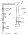
- FIG. 1 shows a two-wire bus system BS2 is shown, which consists of the two wires 11,12, which are connected to a power supply.
- bus coupling units BA2 With the wires 11,12 bus coupling units BA2 are connected, which are also designed two-wire.
- a bus coupler BA2 serves to connect an external device (not shown) to the data bus so that this device receives data or other signals from the bus and / or supplies to the bus.
- the power supply serves to supply all bus coupling units BA2 of the two-wire bus system via the wires 11,12.
- the supply current is superimposed with the pulses of the data telegrams.
- the bus coupling units BA2 can exchange data telegrams with each other.
- a center is not present in this embodiment.
- the four-wire bus system BS4 has four wires 14,15,16,17, of which the wires 14 and 15 conduct the supply current, while the wires 16,17 transmit the information.
- Four-wire bus coupling units BA4 are also connected to the data bus BS4.
- the bus coupling units BA2 and BA4 are part of the bus installation. External devices can be connected to the bus couplers.
- the two bus systems BS2 and BS4 are interconnected by a converter 20, which will be explained in detail.
- a bus coupling unit BA2 can communicate directly with a bus coupling unit BA4.
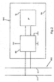
- FIG. 2 shows the structure of a bus coupler BA2 of the two-wire bus system.
- the bus coupling unit BA2 contains a telegram unit TE and a bus connection unit BE.
- the telegram unit TE contains a microprocessor. It is able to generate data telegrams in accordance with the standardized bus protocol on the basis of externally supplied signals and to evaluate such data telegrams that have been received.
- the telegram unit TE forms the information technology part of the bus coupler BA.
- the bus connection unit BE serves for the physical connection to the wires 11, 12 and the preparation of the impulses.
- the telegram unit TE and the bus connection unit BE are interconnected by a data reception line and a data transmission line.
- a bus coupling unit BA4 of the four-wire bus system is not specifically shown.
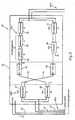
- FIG. 3 shows the converter 20.
- this contains a bus connection unit BE4 of the four-wire bus system and a bus connection unit BE2 of the two-wire bus system.
- the power supply of the converter 20 via the power supply wires 14,15 of the bus system BS4.
- the wires 16, 17 of the four-wire bus system are connected to the output of a transmitting stage 26 and to the input of a receiving stage 27 of the bus connecting unit BE4.
- the input of the receiving stage and the output of the transmitting stage are symmetrical.
- the bus connection unit BE2 contains a transmission stage 30 whose input is coupled to the output of the reception stage 27.
- the output of the transmission stage 30 is connected via a current limiting circuit 31 to the data bus BS2.
- the bus connection unit BE2 also contains a reception stage 32 comprising a level adjustment stage 33 and a pulse regeneration stage 34. Between the reception stage 32 and the data bus BS2 a DC decoupling 35 is connected, which keeps the power supply of the data bus from the reception stage 32.
- the receiving stage 32 of the bus connection unit BE2 is coupled to the transmission stage 26 of the bus connection unit BE4.
- a galvanic isolation stage 42 and 43 is provided for potential separation.
- This isolator consists of an optocoupler or an inductive transformer.
- Bus telegrams which are transmitted on the four-wire bus system BS4 are transmitted by the converter 20 via the receiving stage 27 and the transmission stage 30 to the bus system BS2.
- Information that is generated on the bus system BS2 are transmitted via the receiving stage 32 and the transmission stage 26 from the converter 20 to the bus system BS4.
Landscapes
- Engineering & Computer Science (AREA)
- Computer Networks & Wireless Communication (AREA)
- Signal Processing (AREA)
- Small-Scale Networks (AREA)
- Cable Transmission Systems, Equalization Of Radio And Reduction Of Echo (AREA)
- Input Circuits Of Receivers And Coupling Of Receivers And Audio Equipment (AREA)
Description
- Die Erfindung betrifft einen Umsetzer für Installations-Bussysteme zur Ermöglichung einer Kommunikation zwischen einem Zweidraht- und einem Vierdraht-Bussystem, welche im gleichen Busprotokoll betrieben sind, wobei jedes Bussystem Busankoppler aufweist, die jeweils eine Telegrammeinheit zur Erzeugung von Bustelegrammen aus externen Signalen, oder umgekehrt, und eine Busanschlusseinheit mit Sendestufe und Empfangsstufe für Bustelegramme enthalten.
- Im Bereich der Gebäudesystemtechnik gibt es zwei verschiedene Grundtypen von Bussystemen, über welche digitale Datentelegramme übertragen werden können. Bei einem Zweidraht-Bus wird über dieselben Leitungen sowohl die Information als auch der Versorgungsstrom für die Busankoppler übertragen. In den Busankopplern werden Versorgungsstrom und Information voneinander getrennt bzw. zusammengeführt. Ein eingeführtes System in dieser Technik ist der European Installation Bus (EIB). Der Vorteil eines Zweidraht-Bussystems ist die einfache Verbindungsleitung.
- Bei einem Vierdraht-Bussystem werden die Informationen und der Versorgungsstrom über getrennte Aderpaare geführt. Der Aufwand für die Trennung von Versorgungsstrom und Information entfällt, wodurch die Busankoppler einfach und kostengünstig sind.
- Installations-Bussysteme werden in einem Gebäude unabhängig von der Netzstromversorgung fest installiert. Sie werden benutzt, um Daten, Informationen, Befehle u.dgl. zu übertragen. An den Anschlussstellen befinden sich Busankoppler, an die externe Geräte angeschlossen werden. Die externen Geräte sind häufig Sensoren, Aktoren, z.B. Stellglieder, oder manuelle Eingabevorrichtungen, wie Schalter oder Dimmer. In einem Gebäude kommt es vor, dass für bestimmte Strecken Zweidrahtleitungen zur Verfügung stehen und für andere Strecken Vierdrahtleitungen. Wenn diese installierten Leitungen zu einem Datenbus zusammengeschaltet werden, müsste normalerweise ein einheitliches Zweidraht-Bussystem gebildet werden. Dieses erfordert einen höheren Aufwand bei den Busankopplern und nutzt die vorhandenen Vierdrahtleitungen nicht aus.
- Ein weiteres Merkmal von Installations-Bussystemen besteht darin, dass die Busankoppler standardisiert sind. Die Busankoppler enthalten eine Telegrammeinheit zur Erzeugung bzw. Auswertung von Bustelegrammen und eine Busanschlusseinheit mit Sendestufe und Empfangsstufe für die Bustelegramme. Die Telegrammeinheit bildet den Informationsteil und die Busanschlusseinheit bildet den physischen Busanschluss zum Verbinden des Informationsteils mit dem Datenbus.
- In EP-A-0566935 ist ein Schnittstellenbaustein zum Verbinden zweier Bussegmente beschrieben. Der Schnittstellenbausteil dient für einen Wechsel von bidirektionalem Betrieb einer Zweidraht-Busleitung zu unidirektionalem Betrieb zweier Zweidraht-Busleitungen, also einem unidirektionalen Vierdraht-Betrieb. Im unidirektionalen Betrieb sind erheblich größere Entfernungen als im bidirektionalen Betrieb übertragbar. Der Schnittstellenbausteil enthält jeweils einen Bustreiber mit einem Sender und einem Empfänger. Er bewirkt eine Verstärkung der ankommenden Signale zum Zwecke der Weiterleitung. In dem Schnittstellenbausteil ist der Empfänger der einen Zweidrahtleitung mit dem Sender der anderen Zweidrahtleitung gekoppelt und umgekehrt. Auf diese Weise erfolgt ein bidirektionaler Betrieb mit Streckenverstärkung. Die Stromversorgung erfolgt ebenfalls über das Bussystem.
- Der Erfindung liegt die Aufgabe zugrunde, einen Umsetzer für Installations-Bussysteme zu schaffen, mit dem auf einfache Weise ein Vierdraht-Bussystem und ein Zweidraht-Bussystem, welche im gleichen Busprotokoll betrieben werden, miteinander kombiniert werden können.
- Der erfindungsgemäße Umsetzer ist durch den Anspruch 1 bezeichnet. Er besteht aus einem Gerät, welches - vorzugsweise im selben Gehäuse - jeweils eine Busanschlusseinheit jedes der beiden Bustypen enthält, jedoch ohne Telegrammeinheit. Die Busanschlusseinheiten sind derart zusammengefasst, dass die Empfangsstufe jeder der beiden Busanschlusseinheiten mit der Sendestufe der anderen Busanschlusseinheit gekoppelt ist. Auf diese Weise wird aus standardisierten Busanschlusseinheiten der beiden Systeme ein Umsetzer zusammengesetzt, welcher es ermöglicht, die beiden Datenbusse, nämlich einen Zweidraht-Bus und einen Vierdraht-Bus, zusammenzuschalten, wobei jeder Bus in der Weise betrieben wird, dass seine Vorteile ausgenutzt werden. Der Vierdraht-Bus kann also mit einfachen und kostengünstigen Busankopplern ausgestattet werden, während der Zweidraht-Bus aufwendigere Busankoppler mit Gleichspannungsauskopplung erfordert. Ein Hersteller, der Busankoppler für jedes der beiden Bussysteme serienmäßig liefert, kann den erfindungsgemäßen Umsetzer aus Komponenten seines Herstellungsprogramms leicht zusammensetzen, ohne dass hierzu neue Schaltungen und Geräte erforderlich sind.
- Ein weiterer Vorteil besteht darin, dass die Telegrammeinheiten der Busankoppler beider Systeme, die den informationstechnischen Teil bilden, generell von gleicher Bauart sein können. In beiden Systemen kann beispielsweise der gleiche Mikrocontroller verwendet werden, der auf das gemeinsame Busprotokoll abgestimmt ist.
- Der erfindungsgemäße Umsetzer bewirkt eine bidirektionale Umsetzung zwischen einem Vierdraht-Bussystem und einem Zweidraht-Bussystem.
- Sollte in einem der beiden zusammengefügten Systeme ein größerer Funktionsumfang realisiert sein als im anderen System, so wäre die Busanschlusseinheit des anderen Systems auf den größeren Funktionsumfang aufzurüsten.
- Die Stromversorgung der Komponenten des Umsetzers kann entweder über das Zweidraht-Bussystem oder über das Vierdraht-Bussystem erfolgen. Eine Versorgung - über das Vierdraht-Bussystem hat den Vorteil, dass die Versorgungsspannung an den Leitungen bereits zur Verfügung steht und keiner Auskopplung bedarf.
- Optional kann zwischen den beiden Busanschlusseinheiten im Umsetzer eine galvanische Trennstufe vorgesehen sein, um unerwünschte zusätzliche Kopplungen zu vermeiden und zu verhindern, dass Störsignale über den Umsetzer übertragen werden. Eine solche galvanische Kopplung erfolgt vorzugsweise über Optokoppler oder induktive Übertrager.
- Im Folgenden wird unter Bezugnahme auf die Zeichnungen ein Ausführungsbeispiel der Erfindung näher erläutert. Diese Beschreibung ist nicht so zu verstehen, dass sie den Schutzbereich der Erfindung beschränkt. Dieser wird vielmehr durch die Ansprüche bestimmt.
- Es zeigen:
- Fig. 1
- ein kombiniertes Bussystem aus einem Zweidraht-Bussystem und einem Vierdraht-Bussystem, die durch einen Umsetzer miteinander gekoppelt sind,
- Fig. 2
- ein Blockschaltbild eines Busankopplers des Zweidraht-Bussystems, und
- Fig. 3
- ein Blockschaltbild des Umsetzers.
- In Figur 1 ist ein Zweidraht-Bussystem BS2 dargestellt, das aus den beiden Drähten 11,12 besteht, welche an eine Stromversorgung angeschlossen sind. Mit den Drähten 11,12 sind Busankoppler BA2 verbunden, die ebenfalls zweidrähtig ausgeführt sind. Ein Busankoppler BA2 dient dazu, ein externes Gerät (nicht dargestellt) an den Datenbus anzuschließen, so dass dieses Gerät Daten oder andere Signale von dem Bus empfängt und/oder an den Bus liefert. Die Stromversorgung dient zur Versorgung sämtlicher Busankoppler BA2 des Zweidraht-Bussystems über die Drähte 11,12. Dem Versorgungsstrom werden die Impulse der Datentelegramme überlagert. Die Busankoppler BA2 können Datentelegramme untereinander austauschen. Eine Zentrale ist bei diesem Ausführungsbeispiel nicht vorhanden. Das Vierdraht-Bussystem BS4 weist vier Drähte 14,15,16,17 auf, von denen die Drähte 14 und 15 den Versorgungsstrom leiten, während die Drähte 16,17 die Information übertragen. An den Datenbus BS4 sind ebenfalls vieradrig Busankoppler BA4 angeschlossen. Die Busankoppler BA2 und BA4 sind Bestandteil der Businstallation. An die Busankoppler können jeweils externe Geräte angeschlossen werden.
- Die beiden Bussysteme BS2 und BS4 sind durch einen Umsetzer 20 miteinander verbunden, der noch im Einzelnen erläutert wird. Auf diese Weise kann ein Busankoppler BA2 direkt mit einem Busankoppler BA4 kommunizieren.
- Figur 2 zeigt den Aufbau eines Busankopplers BA2 des Zweidraht-Bussystems. Der Busankoppler BA2 enthält eine Telegrammeinheit TE und eine Busanschlusseinheit BE. Die Telegrammeinheit TE enthält einen Mikroprozessor. Sie ist imstande, aufgrund von extern zugeführten Signalen Datentelegramme entsprechend dem standardisierten Busprotokoll zu erzeugen und solche Datentelegramme, die empfangen wurden, auszuwerten. Die Telegrammeinheit TE bildet den informationstechnischen Teil des Busankopplers BA. Die Busanschlusseinheit BE dient der physischen Ankopplung an die Drähte 11,12 und der Aufbereitung der Impulse. Die Telegrammeinheit TE und die Busanschlusseinheit BE sind durch eine Datenempfangsleitung und eine Datensendeleitung miteinander verbunden.
- Ein Busankoppler BA4 des Vierdraht-Bussystems ist nicht eigens dargestellt.
- Figur 3 zeigt den Umsetzer 20. Dieser enthält in einem gemeinsamen Gerät 25 eine Busanschlusseinheit BE4 des Vierdraht-Bussystems und eine Busanschlusseinheit BE2 des Zweidraht-Bussystems.
- Bei dem dargestellten Ausführungsbeispiel erfolgt die Stromversorgung des Umsetzers 20 über die Stromversorgungsdrähte 14,15 des Bussystems BS4.
- Die Drähte 16,17 des Vierdraht-Bussystems sind mit dem Ausgang einer Sendestufe 26 und dem Eingang einer Empfangsstufe 27 der Busanschlusseinheit BE4 verbunden. Der Eingang der Empfangsstufe und der Ausgang der Sendestufe sind jeweils symmetrisch.
- Die Busanschlusseinheit BE2 enthält eine Sendestufe 30, deren Eingang mit dem Ausgang der Empfangsstufe 27 gekoppelt ist. Der Ausgang der Sendestufe 30 ist über eine Strombegrenzungsschaltung 31 mit dem Datenbus BS2 verbunden.
- Die Busanschlusseinheit BE2 enthält ferner eine Empfangsstufe 32 aus einer Pegelanpassungsstufe 33 und einer Impulsregenerationsstufe 34. Zwischen die Empfangsstufe 32 und den Datenbus BS2 ist eine DC-Abkopplung 35 geschaltet, welche die Stromversorgung des Datenbusses von der Empfangsstufe 32 fernhält.
- Über eine Leitung 40 ist die Empfangsstufe 32 der Busanschlusseinheit BE2 mit der Sendestufe 26 der Busanschlusseinheit BE4 gekoppelt. Über eine Leitung 41 ist der Ausgang der Empfangsstufe 27 der Busanschlusseinheit BE4 mit dem Eingang der Sendestufe 30 der Busanschlusseinheit BE2 gekoppelt. In jeder der Leitungen 40,41 ist eine galvanische Trennstufe 42 bzw. 43 zur Potentialtrennung vorgesehen. Diese Trennstufe besteht aus einem Optokoppler oder einem induktiven Übertrager.
- Bustelegramme, die auf dem Vierdraht-Bussystem BS4 übertragen werden, werden durch den Umsetzer 20 über die Empfangsstufe 27 und die Sendestufe 30 auf das Bussystem BS2 übertragen. Informationen, die auf dem Bussystem BS2 erzeugt werden, werden über die Empfangsstufe 32 und die Sendestufe 26 von dem Umsetzer 20 auf das Bussystem BS4 übertragen.
Claims (5)
- Umsetzer für Installations-Bussysteme zur Ermöglichung einer Kommunikation zwischen einem Zweidraht-Bussystem (BS2), bei dem Versorgungsstrom und Information auf demselben Aderpaar übertragen werden, und einem Vierdraht-Bussystem (BS4), bei welchem Informationen und Versorgungsstrom über getrennte Aderpaare (16,17;14,15) geführt sind, wobei das Zweidraht-Bussystem und das Vierdrahtbussystem im gleichen Busprotokoll betrieben sind und wobei jedes Bussystem Busankoppler (BA2,BA4) aufweist, die jeweils eine Telegrammeinheit (TE) zur Erzeugung von Bustelegrammen aus externen Signalen, oder umgekehrt, und eine Busanschlusseinheit (BE) mit Sendestufe und Empfangsstufe für Bustelegramme enthalten,
dadurch gekennzeichnet,
dass Busanschlusseinheiten (BE2,BE4) der beiden Bussysteme ohne jeweilige Telegrammeinheiten (TE) in einem Gerät (25) derart zusammengefasst sind, dass die Empfangsstufen (27,32) jeder der beiden Busanschlusseinheiten (BE2,BE4) mit der Sendestufe (26,30) der anderen Busanschlusseinheit gekoppelt ist, und dass die in dem Gerät (25) enthaltene Busanschlusseinheit (BE2) des Zweidraht-Bussystems eine DC-Abkopplung (35) enthält. - Umsetzer nach Anspruch 1, dadurch gekennzeichnet, dass die Kopplung zwischen Empfangsstufe und Sendestufe über eine galvanische Trennstufe (42,43) erfolgt.
- Umsetzer nach Anspruch 2, dadurch gekennzeichnet, dass die Trennstufe einen Optokoppler oder induktiven Übertrager aufweist.
- Umsetzer nach einem der Ansprüche 1 - 3, dadurch gekennzeichnet, dass die Stromversorgung des Gerätes (25) über den Versorgungsteil des Vierdraht-Bussystems (BS4) erfolgt.
- Umsetzer nach einem der Ansprüche 1 - 4, dadurch gekennzeichnet, dass die Stromversorgung des Gerätes (25) über das Zweidraht-Bussystem (BS2) erfolgt.
Applications Claiming Priority (2)
| Application Number | Priority Date | Filing Date | Title |
|---|---|---|---|
| DE20318766U | 2003-12-04 | ||
| DE20318766U DE20318766U1 (de) | 2003-12-04 | 2003-12-04 | Umsetzer für Installations-Bussysteme |
Publications (2)
| Publication Number | Publication Date |
|---|---|
| EP1538784A1 EP1538784A1 (de) | 2005-06-08 |
| EP1538784B1 true EP1538784B1 (de) | 2006-10-18 |
Family
ID=34442549
Family Applications (1)
| Application Number | Title | Priority Date | Filing Date |
|---|---|---|---|
| EP04028504A Expired - Lifetime EP1538784B1 (de) | 2003-12-04 | 2004-12-02 | Umsetzer für Installations-Bussysteme |
Country Status (4)
| Country | Link |
|---|---|
| EP (1) | EP1538784B1 (de) |
| AT (1) | ATE343280T1 (de) |
| DE (2) | DE20318766U1 (de) |
| ES (1) | ES2274373T3 (de) |
Families Citing this family (3)
| Publication number | Priority date | Publication date | Assignee | Title |
|---|---|---|---|---|
| DE102006035046B4 (de) * | 2006-07-28 | 2013-05-29 | Insta Elektro Gmbh | Elektrisches/elektronisches Zentralgerät |
| DE102009005431A1 (de) * | 2009-01-19 | 2010-07-22 | Wilo Se | Buskoppler mit Netzteil |
| DE102009014709A1 (de) * | 2009-03-27 | 2010-10-07 | Festool Gmbh | Steuerungseinrichtung für eine portable elektrische Maschine mit einem Kommunikationsbus und Maschine |
Family Cites Families (9)
| Publication number | Priority date | Publication date | Assignee | Title |
|---|---|---|---|---|
| DE3733467A1 (de) * | 1987-09-30 | 1989-04-20 | Siemens Ag | Schaltungsanordnung zur durchschaltung von standverbindungen in kommunikationsnetzen |
| DE4210023A1 (de) * | 1992-03-27 | 1993-09-30 | Sel Alcatel Ag | Digitales Nachrichtenübertragungssystem mit elektrischen symmetrischen Zweidraht-Leitungen unter Verwendung von Phantomkreisen |
| DE4213569C2 (de) * | 1992-04-24 | 1997-01-30 | Siemens Ag | Schnittstellenbaustein zum Verbinden zweier Bussegmente |
| DE9401402U1 (de) * | 1993-03-26 | 1994-03-31 | Siemens AG, 80333 München | Anschlußadapter für netzgespeiste und busgesteuerte Geräte |
| FR2720576B1 (fr) * | 1994-05-24 | 1996-06-21 | Sgs Thomson Microelectronics | Interface compatible pour installation de commande d'appareils domestiques industriels et professionnels. |
| DE19622366B4 (de) * | 1996-06-04 | 2006-01-26 | Deutsche Telekom Ag | ISDN-Anschlußsystem |
| DE29616064U1 (de) * | 1996-09-14 | 1996-12-05 | Insta Elektro GmbH & Co KG, 58511 Lüdenscheid | Elektronische Baugruppen zur Erstellung einer Datenkopplung von geringem Volumen für die Übertragung von Daten in der Gebäudesystemtechnik |
| DE29701136U1 (de) * | 1997-01-23 | 1997-06-12 | Insta Elektro GmbH & Co KG, 58511 Lüdenscheid | Busankoppler |
| DE10205797A1 (de) * | 2002-02-13 | 2003-09-04 | Merten Gmbh & Co Kg | Lokales integriertes Daten- und Telefonnetz |
-
2003
- 2003-12-04 DE DE20318766U patent/DE20318766U1/de not_active Expired - Lifetime
-
2004
- 2004-12-02 ES ES04028504T patent/ES2274373T3/es not_active Expired - Lifetime
- 2004-12-02 DE DE502004001788T patent/DE502004001788D1/de not_active Expired - Lifetime
- 2004-12-02 AT AT04028504T patent/ATE343280T1/de active
- 2004-12-02 EP EP04028504A patent/EP1538784B1/de not_active Expired - Lifetime
Also Published As
| Publication number | Publication date |
|---|---|
| ES2274373T3 (es) | 2007-05-16 |
| EP1538784A1 (de) | 2005-06-08 |
| ATE343280T1 (de) | 2006-11-15 |
| DE20318766U1 (de) | 2005-04-21 |
| DE502004001788D1 (de) | 2006-11-30 |
Similar Documents
| Publication | Publication Date | Title |
|---|---|---|
| EP0344609B1 (de) | Digitales Signalübertragungssystem für die Hausleittechnik | |
| DE69719631T2 (de) | Fernspeisungssystem für Netzwerkelemente | |
| EP2000866B1 (de) | Überwachungseinrichtung zur Erkennung einer fehlerhaften Adressierung eines Slaves in einem Feldbus-System | |
| EP2823602B1 (de) | Buskommunikationsvorrichtung | |
| EP0809222A1 (de) | Anordnung zur Datenübertragung in Prozessleitsystemen | |
| EP1410577B1 (de) | Netzwerkkomponente für ein optisches netzwerk mit notlauffunktion, insbesondere für ein optisches netzwerk in ringtopologie | |
| EP0917324A2 (de) | Empfangschaltung für ein CAN-System | |
| DE2826017A1 (de) | Datenfernverarbeitungsgeraet | |
| EP1538784B1 (de) | Umsetzer für Installations-Bussysteme | |
| DE102017213365B4 (de) | Kommunikationsvorrichtung, System und Verfahren | |
| DE3687047T2 (de) | Uebertragungsschaltung. | |
| EP1690390B1 (de) | Verfahren zur übertragung von daten über einen datenbus sowie system und gateway zur durchführung des verfahrens | |
| DE19916894A1 (de) | Bussystem | |
| EP3632054B1 (de) | Bestimmung von datenbusteilnehmern eines lokalbusses | |
| DE69027766T2 (de) | Netzwerksystem für die datenübertragung | |
| EP1759252B1 (de) | As-interface-netzwerk für grosse entfernungen | |
| EP0419711A1 (de) | Schnittstellenbaustein zur Ankopplung modulierter Signale | |
| DE102004032839B3 (de) | ASI-System zum Anschluß mehrerer Sensoren und/oder Aktuatoren an eine Steuerung | |
| DE8915950U1 (de) | Schnittstellenbaustein für eine Busschnittstelle | |
| DE3420795C2 (de) | Verfahren zur Übertragung von digitalen und analogen Signalen zwischen einer Zentrale und mehreren Unterstationen | |
| EP1548991B1 (de) | Transformatorische Busankopplung | |
| DE4232922C2 (de) | Anordnung zur Datenübertragung in Prozeßleitsystemen | |
| DE102013220155A1 (de) | Auskoppeleinheit für einen Zweileiter-Feldbus zum Lesen von Bustelegrammen | |
| DE4412921C2 (de) | Verfahren und Schaltungsanordnung zur gleichzeitigen Übertragung von Daten und Hilfsenergie | |
| DE10155562B4 (de) | Vorrichtung zur Signalweiterleitung |
Legal Events
| Date | Code | Title | Description |
|---|---|---|---|
| PUAI | Public reference made under article 153(3) epc to a published international application that has entered the european phase |
Free format text: ORIGINAL CODE: 0009012 |
|
| AK | Designated contracting states |
Kind code of ref document: A1 Designated state(s): AT BE BG CH CY CZ DE DK EE ES FI FR GB GR HU IE IS IT LI LT LU MC NL PL PT RO SE SI SK TR |
|
| AX | Request for extension of the european patent |
Extension state: AL BA HR LV MK YU |
|
| 17P | Request for examination filed |
Effective date: 20050914 |
|
| AKX | Designation fees paid |
Designated state(s): AT BE BG CH CY CZ DE DK EE ES FI FR GB GR HU IE IS IT LI LT LU MC NL PL PT RO SE SI SK TR |
|
| GRAP | Despatch of communication of intention to grant a patent |
Free format text: ORIGINAL CODE: EPIDOSNIGR1 |
|
| GRAS | Grant fee paid |
Free format text: ORIGINAL CODE: EPIDOSNIGR3 |
|
| GRAA | (expected) grant |
Free format text: ORIGINAL CODE: 0009210 |
|
| AK | Designated contracting states |
Kind code of ref document: B1 Designated state(s): AT BE BG CH CY CZ DE DK EE ES FI FR GB GR HU IE IS IT LI LT LU MC NL PL PT RO SE SI SK TR |
|
| PG25 | Lapsed in a contracting state [announced via postgrant information from national office to epo] |
Ref country code: SK Free format text: LAPSE BECAUSE OF FAILURE TO SUBMIT A TRANSLATION OF THE DESCRIPTION OR TO PAY THE FEE WITHIN THE PRESCRIBED TIME-LIMIT Effective date: 20061018 Ref country code: IT Free format text: LAPSE BECAUSE OF FAILURE TO SUBMIT A TRANSLATION OF THE DESCRIPTION OR TO PAY THE FEE WITHIN THE PRESCRIBED TIME-LIMIT;WARNING: LAPSES OF ITALIAN PATENTS WITH EFFECTIVE DATE BEFORE 2007 MAY HAVE OCCURRED AT ANY TIME BEFORE 2007. THE CORRECT EFFECTIVE DATE MAY BE DIFFERENT FROM THE ONE RECORDED. Effective date: 20061018 Ref country code: PL Free format text: LAPSE BECAUSE OF FAILURE TO SUBMIT A TRANSLATION OF THE DESCRIPTION OR TO PAY THE FEE WITHIN THE PRESCRIBED TIME-LIMIT Effective date: 20061018 Ref country code: FI Free format text: LAPSE BECAUSE OF FAILURE TO SUBMIT A TRANSLATION OF THE DESCRIPTION OR TO PAY THE FEE WITHIN THE PRESCRIBED TIME-LIMIT Effective date: 20061018 Ref country code: IE Free format text: LAPSE BECAUSE OF FAILURE TO SUBMIT A TRANSLATION OF THE DESCRIPTION OR TO PAY THE FEE WITHIN THE PRESCRIBED TIME-LIMIT Effective date: 20061018 Ref country code: CZ Free format text: LAPSE BECAUSE OF FAILURE TO SUBMIT A TRANSLATION OF THE DESCRIPTION OR TO PAY THE FEE WITHIN THE PRESCRIBED TIME-LIMIT Effective date: 20061018 Ref country code: SI Free format text: LAPSE BECAUSE OF FAILURE TO SUBMIT A TRANSLATION OF THE DESCRIPTION OR TO PAY THE FEE WITHIN THE PRESCRIBED TIME-LIMIT Effective date: 20061018 Ref country code: RO Free format text: LAPSE BECAUSE OF FAILURE TO SUBMIT A TRANSLATION OF THE DESCRIPTION OR TO PAY THE FEE WITHIN THE PRESCRIBED TIME-LIMIT Effective date: 20061018 Ref country code: LT Free format text: LAPSE BECAUSE OF FAILURE TO SUBMIT A TRANSLATION OF THE DESCRIPTION OR TO PAY THE FEE WITHIN THE PRESCRIBED TIME-LIMIT Effective date: 20061018 |
|
| REG | Reference to a national code |
Ref country code: GB Ref legal event code: FG4D Free format text: NOT ENGLISH |
|
| REG | Reference to a national code |
Ref country code: CH Ref legal event code: EP Ref country code: IE Ref legal event code: FG4D Free format text: LANGUAGE OF EP DOCUMENT: GERMAN |
|
| REF | Corresponds to: |
Ref document number: 502004001788 Country of ref document: DE Date of ref document: 20061130 Kind code of ref document: P |
|
| PG25 | Lapsed in a contracting state [announced via postgrant information from national office to epo] |
Ref country code: BE Free format text: LAPSE BECAUSE OF NON-PAYMENT OF DUE FEES Effective date: 20061231 Ref country code: MC Free format text: LAPSE BECAUSE OF NON-PAYMENT OF DUE FEES Effective date: 20061231 |
|
| PG25 | Lapsed in a contracting state [announced via postgrant information from national office to epo] |
Ref country code: BG Free format text: LAPSE BECAUSE OF FAILURE TO SUBMIT A TRANSLATION OF THE DESCRIPTION OR TO PAY THE FEE WITHIN THE PRESCRIBED TIME-LIMIT Effective date: 20070118 Ref country code: SE Free format text: LAPSE BECAUSE OF FAILURE TO SUBMIT A TRANSLATION OF THE DESCRIPTION OR TO PAY THE FEE WITHIN THE PRESCRIBED TIME-LIMIT Effective date: 20070118 Ref country code: DK Free format text: LAPSE BECAUSE OF FAILURE TO SUBMIT A TRANSLATION OF THE DESCRIPTION OR TO PAY THE FEE WITHIN THE PRESCRIBED TIME-LIMIT Effective date: 20070118 |
|
| PG25 | Lapsed in a contracting state [announced via postgrant information from national office to epo] |
Ref country code: IS Free format text: LAPSE BECAUSE OF FAILURE TO SUBMIT A TRANSLATION OF THE DESCRIPTION OR TO PAY THE FEE WITHIN THE PRESCRIBED TIME-LIMIT Effective date: 20070218 |
|
| PG25 | Lapsed in a contracting state [announced via postgrant information from national office to epo] |
Ref country code: PT Free format text: LAPSE BECAUSE OF FAILURE TO SUBMIT A TRANSLATION OF THE DESCRIPTION OR TO PAY THE FEE WITHIN THE PRESCRIBED TIME-LIMIT Effective date: 20070319 |
|
| GBV | Gb: ep patent (uk) treated as always having been void in accordance with gb section 77(7)/1977 [no translation filed] |
Effective date: 20061018 |
|
| REG | Reference to a national code |
Ref country code: ES Ref legal event code: FG2A Ref document number: 2274373 Country of ref document: ES Kind code of ref document: T3 Ref country code: IE Ref legal event code: FD4D |
|
| ET | Fr: translation filed | ||
| PLBE | No opposition filed within time limit |
Free format text: ORIGINAL CODE: 0009261 |
|
| STAA | Information on the status of an ep patent application or granted ep patent |
Free format text: STATUS: NO OPPOSITION FILED WITHIN TIME LIMIT |
|
| 26N | No opposition filed |
Effective date: 20070719 |
|
| PG25 | Lapsed in a contracting state [announced via postgrant information from national office to epo] |
Ref country code: GB Free format text: LAPSE BECAUSE OF FAILURE TO SUBMIT A TRANSLATION OF THE DESCRIPTION OR TO PAY THE FEE WITHIN THE PRESCRIBED TIME-LIMIT Effective date: 20061018 |
|
| BERE | Be: lapsed |
Owner name: MERTEN G.M.B.H. & CO. KG Effective date: 20061231 |
|
| PG25 | Lapsed in a contracting state [announced via postgrant information from national office to epo] |
Ref country code: GR Free format text: LAPSE BECAUSE OF FAILURE TO SUBMIT A TRANSLATION OF THE DESCRIPTION OR TO PAY THE FEE WITHIN THE PRESCRIBED TIME-LIMIT Effective date: 20070119 |
|
| PG25 | Lapsed in a contracting state [announced via postgrant information from national office to epo] |
Ref country code: EE Free format text: LAPSE BECAUSE OF FAILURE TO SUBMIT A TRANSLATION OF THE DESCRIPTION OR TO PAY THE FEE WITHIN THE PRESCRIBED TIME-LIMIT Effective date: 20061018 |
|
| PG25 | Lapsed in a contracting state [announced via postgrant information from national office to epo] |
Ref country code: LU Free format text: LAPSE BECAUSE OF NON-PAYMENT OF DUE FEES Effective date: 20061202 Ref country code: TR Free format text: LAPSE BECAUSE OF FAILURE TO SUBMIT A TRANSLATION OF THE DESCRIPTION OR TO PAY THE FEE WITHIN THE PRESCRIBED TIME-LIMIT Effective date: 20061018 Ref country code: HU Free format text: LAPSE BECAUSE OF FAILURE TO SUBMIT A TRANSLATION OF THE DESCRIPTION OR TO PAY THE FEE WITHIN THE PRESCRIBED TIME-LIMIT Effective date: 20070419 |
|
| PG25 | Lapsed in a contracting state [announced via postgrant information from national office to epo] |
Ref country code: CY Free format text: LAPSE BECAUSE OF FAILURE TO SUBMIT A TRANSLATION OF THE DESCRIPTION OR TO PAY THE FEE WITHIN THE PRESCRIBED TIME-LIMIT Effective date: 20061018 |
|
| REG | Reference to a national code |
Ref country code: CH Ref legal event code: PL |
|
| PG25 | Lapsed in a contracting state [announced via postgrant information from national office to epo] |
Ref country code: LI Free format text: LAPSE BECAUSE OF NON-PAYMENT OF DUE FEES Effective date: 20081231 Ref country code: CH Free format text: LAPSE BECAUSE OF NON-PAYMENT OF DUE FEES Effective date: 20081231 |
|
| REG | Reference to a national code |
Ref country code: FR Ref legal event code: PLFP Year of fee payment: 12 |
|
| REG | Reference to a national code |
Ref country code: FR Ref legal event code: PLFP Year of fee payment: 13 |
|
| REG | Reference to a national code |
Ref country code: FR Ref legal event code: PLFP Year of fee payment: 14 |
|
| PGFP | Annual fee paid to national office [announced via postgrant information from national office to epo] |
Ref country code: NL Payment date: 20171115 Year of fee payment: 14 Ref country code: FR Payment date: 20171113 Year of fee payment: 14 Ref country code: DE Payment date: 20171129 Year of fee payment: 14 |
|
| PGFP | Annual fee paid to national office [announced via postgrant information from national office to epo] |
Ref country code: AT Payment date: 20171128 Year of fee payment: 14 |
|
| PGFP | Annual fee paid to national office [announced via postgrant information from national office to epo] |
Ref country code: ES Payment date: 20180102 Year of fee payment: 14 |
|
| REG | Reference to a national code |
Ref country code: DE Ref legal event code: R119 Ref document number: 502004001788 Country of ref document: DE |
|
| REG | Reference to a national code |
Ref country code: NL Ref legal event code: MM Effective date: 20190101 |
|
| REG | Reference to a national code |
Ref country code: AT Ref legal event code: MM01 Ref document number: 343280 Country of ref document: AT Kind code of ref document: T Effective date: 20181202 |
|
| PG25 | Lapsed in a contracting state [announced via postgrant information from national office to epo] |
Ref country code: NL Free format text: LAPSE BECAUSE OF NON-PAYMENT OF DUE FEES Effective date: 20190101 |
|
| PG25 | Lapsed in a contracting state [announced via postgrant information from national office to epo] |
Ref country code: FR Free format text: LAPSE BECAUSE OF NON-PAYMENT OF DUE FEES Effective date: 20181231 Ref country code: DE Free format text: LAPSE BECAUSE OF NON-PAYMENT OF DUE FEES Effective date: 20190702 |
|
| PG25 | Lapsed in a contracting state [announced via postgrant information from national office to epo] |
Ref country code: AT Free format text: LAPSE BECAUSE OF NON-PAYMENT OF DUE FEES Effective date: 20181202 |
|
| REG | Reference to a national code |
Ref country code: ES Ref legal event code: FD2A Effective date: 20200131 |
|
| PG25 | Lapsed in a contracting state [announced via postgrant information from national office to epo] |
Ref country code: ES Free format text: LAPSE BECAUSE OF NON-PAYMENT OF DUE FEES Effective date: 20181203 |