EP1538511B1 - Elecktronisches Gerät und Batteriepack - Google Patents
Elecktronisches Gerät und Batteriepack Download PDFInfo
- Publication number
- EP1538511B1 EP1538511B1 EP04257380.8A EP04257380A EP1538511B1 EP 1538511 B1 EP1538511 B1 EP 1538511B1 EP 04257380 A EP04257380 A EP 04257380A EP 1538511 B1 EP1538511 B1 EP 1538511B1
- Authority
- EP
- European Patent Office
- Prior art keywords
- battery pack
- electronic device
- detectable
- main unit
- power
- Prior art date
- Legal status (The legal status is an assumption and is not a legal conclusion. Google has not performed a legal analysis and makes no representation as to the accuracy of the status listed.)
- Expired - Lifetime
Links
Images


Classifications
-
- H—ELECTRICITY
- H01—ELECTRIC ELEMENTS
- H01M—PROCESSES OR MEANS, e.g. BATTERIES, FOR THE DIRECT CONVERSION OF CHEMICAL ENERGY INTO ELECTRICAL ENERGY
- H01M10/00—Secondary cells; Manufacture thereof
- H01M10/42—Methods or arrangements for servicing or maintenance of secondary cells or secondary half-cells
- H01M10/425—Structural combination with electronic components, e.g. electronic circuits integrated to the outside of the casing
-
- G—PHYSICS
- G06—COMPUTING OR CALCULATING; COUNTING
- G06F—ELECTRIC DIGITAL DATA PROCESSING
- G06F1/00—Details not covered by groups G06F3/00 - G06F13/00 and G06F21/00
- G06F1/26—Power supply means, e.g. regulation thereof
-
- H—ELECTRICITY
- H05—ELECTRIC TECHNIQUES NOT OTHERWISE PROVIDED FOR
- H05K—PRINTED CIRCUITS; CASINGS OR CONSTRUCTIONAL DETAILS OF ELECTRIC APPARATUS; MANUFACTURE OF ASSEMBLAGES OF ELECTRICAL COMPONENTS
- H05K7/00—Constructional details common to different types of electric apparatus
- H05K7/14—Mounting supporting structure in casing or on frame or rack
-
- Y—GENERAL TAGGING OF NEW TECHNOLOGICAL DEVELOPMENTS; GENERAL TAGGING OF CROSS-SECTIONAL TECHNOLOGIES SPANNING OVER SEVERAL SECTIONS OF THE IPC; TECHNICAL SUBJECTS COVERED BY FORMER USPC CROSS-REFERENCE ART COLLECTIONS [XRACs] AND DIGESTS
- Y02—TECHNOLOGIES OR APPLICATIONS FOR MITIGATION OR ADAPTATION AGAINST CLIMATE CHANGE
- Y02E—REDUCTION OF GREENHOUSE GAS [GHG] EMISSIONS, RELATED TO ENERGY GENERATION, TRANSMISSION OR DISTRIBUTION
- Y02E60/00—Enabling technologies; Technologies with a potential or indirect contribution to GHG emissions mitigation
- Y02E60/10—Energy storage using batteries
Definitions
- the present invention relates to an electronic device and a battery pack provided therein. More specifically, illustrative embodiments of the present invention relate to a technology that optimizes operation control by acquiring power information of a battery pack.
- Electronic devices include a type of device in which a main unit including various circuits, such as a driving circuit and a control circuit, is equipped with a battery pack and the main unit is driven by electric power supplied from the battery pack.
- the type of device is, for example, an information processing device such as a personal computer.
- This type of electronic device of the related art includes a device (e.g., Japanese Unexamined Patent Application Publication No. 2003-259191 ) which detects the type and voltage of an installed battery pack and an ambient temperature around the battery pack, and which controls the device operation in response to the detected battery pack type and voltage, and ambient temperature.
- a device e.g., Japanese Unexamined Patent Application Publication No. 2003-259191
- a control circuit provided in a main unit such as a power saving circuit, measures power supplied from a battery pack to the main unit at the time the power consumption exceeds a power threshold set beforehand, and controls the power of a central processing unit (CPU).
- CPU central processing unit
- WO 98/10610 describes mobile station operations management based on battery capacity.
- Embodiments of the present invention seek to provide an electronic device and a battery pack which overcome the above problems and which optimize operation control.
- an electronic device driven by power supplied from a battery pack installed in a main unit of the electronic device includes a storing unit, provided in the battery pack, for storing power information of the battery pack, the power information including a maximum power that can be supplied by the battery pack, an acquiring unit, provided in the main unit, for acquiring the power information of the battery pack, and a control unit, provided in the main unit, for controlling the operation of the main unit based on the power information of the battery pack acquired by the acquiring unit.
- the power can be prevented or at least impeded from unintentionally and suddenly turning off due to insufficiency of the power that can be supplied.
- the power information of the battery pack is regularly stored by the storing unit, and the regularly stored power information is continuously or intermittently acquired by the acquiring unit.
- operation control can be optimized in response to a state of use on each occasion.
- the battery pack has thereon a detectable part for enabling detection of the type of the battery pack.
- the main unit has thereon a detecting part for reading the detectable part to detect the type of the battery pack.
- a different type of battery pack can be prevented or at least impeded from being mistakenly inserted.
- a housing for the battery pack has, on an outer surface thereof, one of a detectable projection and a detectable recess as the detectable part, and the main unit has, thereon, as the detecting part, one of a detecting recess into which the detectable projection is to be inserted and a detecting projection to be inserted into the detectable recess.
- a battery pack for use in an electronic device including a detecting part for detecting the type of the battery pack and control unit for performing operation control based on power information stored in the battery pack, whose type is detected, is provided.
- the power information indicates a maximum power that can be supplied by the battery pack.
- the battery pack supplies driving power to a main unit of the electronic device when being installed in the main unit of the electronic device.
- the battery pack is provided with a detectable part by which the type of the battery pack is detected such that the detectable part is read by the detecting part when the battery pack is installed in the main unit of the electronic device.
- a housing for the battery pack has, on an outer surface thereof, one of a detectable projection or a detectable recess as the detectable part, and the type of the battery pack is detected such that a detecting projection provided as the detecting part of the main unit of the electronic device is inserted into the detectable recess, or the detectable projection is inserted into a detecting recess provided as the detecting part of the main unit of the electronic device.
- the above simplified structure can prevent or at least impede a battery pack from being mistakenly inserted.
- PDA personal digital assistants
- network terminals portable information terminals
- workstations portable information terminals
- audio devices battery packs provided therein.
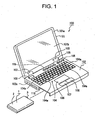
- An electronic device (personal computer) 100 has a display unit 101 and a main unit 102.
- the display unit 101 has a display housing 101a and a display section 101b fixed to the display housing 101a.
- Hinge projections 103 which project upward are provided at right and left ends of a rear-end part of the main unit 102.
- the display unit 101 is rotatably supported by the hinge projections 103.
- An oblong keyboard 104 is provided on the top surface of the main unit 102.
- the keyboard 104 has a plurality of predetermined operation keys 104a thereon.
- a processor such as a central processing unit (CPU), which is described later, is provided in the main unit 102.
- the processor performs processing on a signal input by an operation on each of the operation keys 104a.
- operating devices different from the operation keys 104a for example, so-called "hotkeys" 105 in each of which a one-touch operation enables execution of software, a pointing device 106 on which a movement or the like of a pointer on the display section 101b can be performed by applying a force in an arbitrary direction with a finger, a left button 107 and a right button 108 which correspond to two buttons of a mouse, etc., are arranged.
- a power-on button 109 is disposed on the top surface of the main unit 102.
- a side face 102a of the main unit 102 has, for example, a recess which opens on the left and bottom of the main unit 102. This recess is used as a battery installation part 110.
- the battery installation part 110 has a detecting projection 111 which projects to the left and which functions as a detector, and a connector 112.
- the main unit 102 includes a control unit 113 for performing operation control of the main unit 102, a volatile storage unit functioning as a main storage, a nonvolatile storage unit functioning as an auxiliary storage, and an acquiring unit 114. These units are connected by power lines.
- the control unit 113 is, for example, a CPU, and has functions of loading stored information into the volatile storage, performing various types of arithmetic processing, and writing the results of the processing in the volatile storage unit.
- the volatile storage unit is, for example, a dynamic random access memory (DRAM), and is a memory in which stored information vanishes when power is removed.
- DRAM dynamic random access memory
- the nonvolatile storage unit is, for example, a hard disk drive, an optical disk drive, or the like, and is a memory in which stored information is stored even when power is removed.
- the acquiring unit 114 is, for example, an embedded controller (EC) or a south bridge (SB) on a mother board.
- the acquiring unit 114 has functions, such as detection and acquisition of a connection status of the battery pack to the main unit 102, and a function of controlling the electronic device 100 and each unit of a peripheral device of the electronic device 100 and controlling additional functions, etc. Accordingly, the acquiring unit 114 performs power supply and cutoff for the control unit 113, the volatile storage unit, the nonvolatile storage unit, the mouse used as an input unit, the keyboard 104, the display section 101b used as an output unit, a printer, etc.
- the acquiring unit 114 is connected to the power-on button 109, and has a function of detecting an operation on the power-on button 109 and initiating activation of the electronic device 100.
- the main unit 102 is provided with an ACPI (Advanced Configuration and Power Interface) 115 as a software layer.
- the ACPI is a specification for consolidating control of power management of the electronic device 100.
- the ACPI 115 is an interface unit forming an ACPI mechanism.
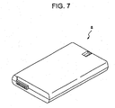
- a battery pack 1 has, for example, a substantially rectangular flat form. Inside a housing 2, a plurality of cells 4 (shown in Fig. 4 ), for example, secondary cells such as lithium-ion cells or ion-polymer cells, and predetermined portions such as a control circuit substrate, are arranged.
- cells 4 shown in Fig. 4
- secondary cells such as lithium-ion cells or ion-polymer cells
- predetermined portions such as a control circuit substrate
- a connector 3 is provided on one side face 2a of the housing 2.
- a detectable recess 2b that functions as a portion to be detected is formed on the side face 2a of the housing 2.
- the battery pack 1 includes a storing unit 5.
- the storing unit 5 is, for example, a microcomputer.
- the storing unit 5 retains various types of information concerning cells 4, such as environmental conditions such as temperature and humidity, power-supply states such as battery's remaining capacity and a load status, a deterioration state, and power information. Accordingly, the storing unit 5 constantly detects power information of the cells 4 and also functions as a power information detecting unit.
- the cells 4 and storing unit 5 of the battery pack 1 and each unit of the main unit 102 are connected to one another by a system bus.
- the storing unit 5 is connected to the acquiring unit 114 by an input/output (I/O) port 116.
- Setting of the battery pack 1 in the battery installation part 110 is performed by inserting the battery pack 1 into the battery installation part 110 so that the connector 3 is directed to the battery installation part 110.
- the detecting projection 111 of the main unit 102 is relatively inserted into the detectable recess 2b of the battery pack 1, as shown in Fig. 6 .
- the battery pack 1 is inserted into an innermost end of the battery installation part 110. Then, the connector 3 is connected to a connector 112 of the main unit 102, whereby setting of the battery pack 1 in the battery installation part 110 is completed. After completing the setting of the battery pack 1 in the battery installation part 110, by supplying power to the main unit 102, the I/O port 116 displays a mechanical identification (ID) of the battery pack 1.
- ID mechanical identification
- the detectable recess 2b is formed on the battery pack 1.
- insertion of the detecting projection 111 into the detectable recess 2b enables setting of the battery pack 1 in the battery installation part 110.
- a battery pack "a” which is identical in size and shape of the battery pack 1 shown in Fig. 1 .
- the power that can be supplied is lower than that of the battery pack 1.
- the battery pack “a” does not have the detectable recess 2b. Accordingly, as shown in Fig. 8 , when the battery pack "a” is inserted in the battery installation part 110, the detecting projection 111 touches a side face of the battery pack "a", so that insertion of the battery pack "a” into the battery installation part 110 is restricted.
- the detecting projection 111 touches the side face of the battery pack "a"
- the battery pack "a” cannot be inserted to an innermost end of the battery installation part 110, and the connector 3 is not connected to the connector 112 of the main unit 102, so that the battery pack "a” partially projects from the main unit 102.
- the battery pack "a" cannot be installed in the main unit 102. This allows a user to easily know that a wrong type of battery pack has been inserted.
- an electronic device having a main unit whose power consumption is smaller than that of the main unit 102 is not provided with a detecting projection. Either the battery pack "a" or the battery pack 1 can be inserted into the main unit of this electronic device.
- the acquiring unit 114 detects the operation on the power-on button 109, and the operation of initiating activation of the electronic device 100 is performed and the acquiring unit 114 supplies power to the control unit 113.
- the value of the I/O port 116 which displays the mechanical ID of the battery pack 1, is read by the acquiring unit 114.
- the acquiring unit 114 acquires information stored in the battery pack 1, for example, power information (the power that can be supplied) configured in design, and transmits the acquired power information to the control unit 113.
- a system bus controller is initialized, and the address of the battery pack 1 is designated on the system bus. This confirms the existence of the battery pack 1. After confirming the existence of the battery pack 1, detection is performed concerning whether the battery pack 1 and the control unit 113 can communicate with each other.
- the acquiring unit 114 acquires various types of information stored in the battery pack 1, for example, power information, and transmits the acquired power information to the control unit 113.
- the control unit 113 Based on the transmitted power information, the control unit 113 sets an optimal operating frequency of the main unit 102. Until the electronic device 100 is activated after the power-on button 109 is operated, based on the power information acquired from the value of the I/O port 116 which displays the mechanical ID, the optimal operating frequency of the main unit 102 is set by the control unit 113.
- the power information of the battery pack 1 is acquired from the storing unit 5 by the acquiring unit 114, and the operation of the main unit 102 is controlled by the control unit 113 based on the power information of the battery pack 1 acquired by the acquiring unit 114.
- a problem of data loss in an information processing device such as a personal computer, can be avoided or at least reduced without causing a situation in which the power unintentionally and suddenly turns off.
- control circuit such as a power saving circuit
- Fig. 9 is a graph showing relationships among the maximum power that can be supplied of the battery pack 1 and parameters.
- the maximum power that can be supplied of the battery pack 1 increases as an ambient temperature around the battery pack 1 increases. It increases as the voltage (cell voltage) of the battery pack 1 increases. It increases as a deterioration factor of the battery pack 1 decreases.
- the maximum power that can be supplied is calculated based on constant detection of the ambient temperature, voltage, and deterioration factor, the calculated value is written in a storage area (RAM) of the storing unit 5, and the written power information is acquired and transmitted to the control unit 113 by the acquiring unit 114.
- RAM storage area
- the acquisition and transmission of the power information by the acquiring unit 114 are continuously or intermittently performed when the electronic device 100 is activated. When the acquisition and transmission are intermittently performed, they are performed at intervals of, for example, eight seconds. Based on the continuously or intermittently transmitted power information, the control unit 113 changes the set optimal operating frequency each time and performs operation control of the main unit 102.
- operation control can be optimized in response to a state of use on each occasion.
- the main unit 102 is provided with the detecting projection 111 as a detecting part and the battery pack 1 is provided with the detectable recess 2b as a detectable part has been described.
- the display unit 101 can be provided with a detecting recess as a detecting part and the battery pack 1 can be provided with a detectable projection as a detectable part.
- the detecting part and the detectable part can be formed by, for example, optical or magnetic devices such as optical sensors or magnetic sensors without using mechanical parts such the detecting projection 111 as the detecting part and the detectable recess 2b as the detectable part.
- the sizes and shapes of the battery pack 1 and the battery pack “a” are not limited to those shown in Figs. 5 and 7 .
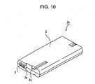
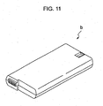
- the battery pack 1A shown in Fig. 10 and the battery pack “b” shown in Fig. 11 which are smaller in size than the battery pack 1 and the battery pack "a", are usable.
- the power that can be supplied is larger than that of the battery pack "b".
- the battery pack 1A is provided with a detectable recess 2C or a detectable projection, and the battery pack "b" is not provided with a detectable recess and a detecting projection.
Landscapes
- Engineering & Computer Science (AREA)
- Theoretical Computer Science (AREA)
- Microelectronics & Electronic Packaging (AREA)
- Physics & Mathematics (AREA)
- General Physics & Mathematics (AREA)
- General Engineering & Computer Science (AREA)
- Chemical & Material Sciences (AREA)
- General Chemical & Material Sciences (AREA)
- Electrochemistry (AREA)
- Chemical Kinetics & Catalysis (AREA)
- Manufacturing & Machinery (AREA)
- Battery Mounting, Suspending (AREA)
- Secondary Cells (AREA)
- Charge And Discharge Circuits For Batteries Or The Like (AREA)
- Power Sources (AREA)
Claims (7)
- Batteriepack (1) zur Verwendung in einem elektronischen Gerät (100), wobei der Batteriepack umfasst:eine Energieinformationsdetektionseinheit (5); und Speichermittel (5), betreibbar zum Speichern von detektierten Energieinformationen des Batteriepacks (1), wobei die Energieinformationen eine maximale Energie angeben, die von dem Batteriepack (1) geliefert werden kann.
- Batteriepack (1) nach Anspruch 1 zur Verwendung in einem elektronischen Gerät (100), einschließlich eines detektierenden Teils (111) zum Detektieren des Typs des Batteriepacks (1) und Steuerungsmittel (113) zum Durchführen von Betriebssteuerung basierend auf den im Speichermittel (5) des Batteriepacks (1), dessen Typ detektiert wird, gespeicherten Energieinformationen, wobei der Batteriepack (1) Betriebsleistung an eine Haupteinheit (102) des elektronischen Gerätes abgibt, wenn er in der Haupteinheit (102) des elektronischen Geräts installiert ist,
wobei der Batteriepack (1) mit einem detektierbaren Teil (2b) versehen ist, durch den der Typ des Batteriepacks (1) detektiert wird, so dass der detektierbare Teil (2b) von dem detektierenden Teil (111) ausgelesen wird, wenn der Batteriepack (1) in der Haupteinheit (102) des elektronischen Gerätes (100) installiert ist. - Batteriepack nach Anspruch 2, wobei ein Gehäuse (2) für den Batteriepack (1) an dessen äußerer Oberfläche einen detektierbaren Vorsprung oder eine detektierbare Vertiefung (2b) als detektierbares Teil aufweist; und
der Typ des Batteriepacks (1) derart detektiert wird, dass ein detektierender Vorsprung (111), der als das detektierende Teil der Haupteinheit (102) des elektronischen Gerätes (1) vorgesehen ist, in die detektierbare Vertiefung (2b) eingesetzt wird oder der detektierbare Vorsprung in eine detektierende Vertiefung eingesetzt wird, die als der detektierende Teil der Haupteinheit (102) des elektronischen Geräts (100) vorgesehen ist. - Elektronisches Gerät (100), das dafür ausgelegt ist, von Energie versorgt zu werden, die von einem Batteriepack (1) nach Anspruch 1 geliefert wird, das in einer Haupteinheit (102) des elektronischen Geräts installiert ist, umfassend:Erfassungsmittel (114), vorgesehen in der Haupteinheit (102), dafür ausgelegt, die Energieinformationen des Batteriepacks (1) zu erfassen, die die maximale Energie, die von dem Batteriepack geliefert werden kann, angeben; undSteuerungsmittel (113), vorgesehen in der Haupteinheit (102), dafür ausgelegt, den Betrieb der Haupteinheit (102) basierend auf den von dem Erfassungsmittel (114) erfassten Energieinformationen des Batteriepacks (1) zu steuern.
- Elektronisches Gerät nach Anspruch 4, wobei die Energieinformationen des Batteriepacks (1) regelmäßig von dem Speichermittel (5) gespeichert werden und die regelmäßig gespeicherten Energieinformationen kontinuierlich oder periodisch von dem Erfassungsmittel (114) erfasst werden.
- Elektronisches Gerät nach Anspruch 5, wobei der Batteriepack (1) auf sich ein detektierbares Teil (2b) zum Ermöglichen der Detektion des Typs des Batteriepacks (1) aufweist; und
die Haupteinheit (102) auf sich ein detektierendes Teil (111) zum Auslesen des detektierbaren Teils aufweist, um den Typ des Batteriepacks (1) zu detektieren. - Elektronisches Gerät nach Anspruch 6, wobei ein Gehäuse (2) für das Batteriepack (1) an dessen äußerer Oberfläche einen detektierbaren Vorsprung oder eine detektierbare Vertiefung (2b) als detektierbares Teil aufweist; und
die Haupteinheit (102) auf sich als das detektierende Teil eine detektierende Vertiefung aufweist, in die der detektierbare Vorsprung einzusetzen ist, oder einen detektierenden Vorsprung (111), der in die detektierbare Vertiefung einzusetzen ist.
Applications Claiming Priority (2)
| Application Number | Priority Date | Filing Date | Title |
|---|---|---|---|
| JP2003401774A JP2005165545A (ja) | 2003-12-01 | 2003-12-01 | 電子機器及びバッテリーパック |
| JP2003401774 | 2003-12-01 |
Publications (3)
| Publication Number | Publication Date |
|---|---|
| EP1538511A2 EP1538511A2 (de) | 2005-06-08 |
| EP1538511A3 EP1538511A3 (de) | 2006-12-06 |
| EP1538511B1 true EP1538511B1 (de) | 2015-02-25 |
Family
ID=34463928
Family Applications (1)
| Application Number | Title | Priority Date | Filing Date |
|---|---|---|---|
| EP04257380.8A Expired - Lifetime EP1538511B1 (de) | 2003-12-01 | 2004-11-29 | Elecktronisches Gerät und Batteriepack |
Country Status (5)
| Country | Link |
|---|---|
| US (3) | US8486547B2 (de) |
| EP (1) | EP1538511B1 (de) |
| JP (1) | JP2005165545A (de) |
| CN (1) | CN100451918C (de) |
| TW (1) | TWI246218B (de) |
Families Citing this family (10)
| Publication number | Priority date | Publication date | Assignee | Title |
|---|---|---|---|---|
| JP4764144B2 (ja) * | 2005-11-18 | 2011-08-31 | 株式会社東芝 | 情報処理装置およびプロセッサ制御方法 |
| JP4551444B2 (ja) * | 2007-12-28 | 2010-09-29 | 富士通株式会社 | 電子機器 |
| TWI394959B (zh) * | 2007-12-31 | 2013-05-01 | Chi Mei Comm Systems Inc | 測試用電源裝置 |
| JP2010157110A (ja) | 2008-12-26 | 2010-07-15 | Sony Corp | 情報処理装置、デバイス制御方法、およびプログラム |
| JP6219687B2 (ja) * | 2013-11-12 | 2017-10-25 | ルネサスエレクトロニクス株式会社 | 半導体装置、電池パック及び携帯端末 |
| CN106571495B (zh) * | 2015-10-08 | 2019-03-19 | 松下知识产权经营株式会社 | 蓄电系统和蓄电方法 |
| KR102142635B1 (ko) * | 2018-03-06 | 2020-08-07 | 주식회사 케이티앤지 | 전력을 공급하는 방법 및 그 디바이스 |
| KR20220100332A (ko) * | 2021-01-08 | 2022-07-15 | 주식회사 엘지에너지솔루션 | 배터리 장치 및 전압 공급 방법 |
| EP4376251A4 (de) * | 2021-07-21 | 2025-02-26 | Panasonic Intellectual Property Management Co., Ltd. | Elektronische vorrichtung und steuerungsverfahren dafür |
| JP7792574B2 (ja) * | 2022-05-09 | 2025-12-26 | パナソニックIpマネジメント株式会社 | バッテリパック、電子機器、通信システム、および通信方法 |
Family Cites Families (19)
| Publication number | Priority date | Publication date | Assignee | Title |
|---|---|---|---|---|
| US4709202A (en) * | 1982-06-07 | 1987-11-24 | Norand Corporation | Battery powered system |
| US5619117A (en) | 1982-06-07 | 1997-04-08 | Norand Corporation | Battery pack having memory |
| JP2983568B2 (ja) | 1990-02-28 | 1999-11-29 | 三洋電機株式会社 | 容量表示装置 |
| US5458991A (en) * | 1993-05-19 | 1995-10-17 | Sl Waber, Inc. | UPS with auto self test |
| US5557188A (en) * | 1994-02-01 | 1996-09-17 | Sun Microsystems, Inc. | Smart battery system and interface |
| JP3627260B2 (ja) * | 1994-09-02 | 2005-03-09 | ソニー株式会社 | バッテリ装置及びこのバッテリ装置の装着装置 |
| JP2716374B2 (ja) * | 1994-09-28 | 1998-02-18 | インターナショナル・ビジネス・マシーンズ・コーポレイション | 情報処理機器、情報処理機器のための給電装置及び給電方法 |
| US5633573A (en) * | 1994-11-10 | 1997-05-27 | Duracell, Inc. | Battery pack having a processor controlled battery operating system |
| JP3575646B2 (ja) | 1995-12-06 | 2004-10-13 | ソニー株式会社 | バツテリーパツク |
| KR980012672A (ko) * | 1996-07-16 | 1998-04-30 | 손욱 | 지능형 배터리 장치 |
| US5870685A (en) * | 1996-09-04 | 1999-02-09 | Ericsson Inc. | Mobile station operations management based on battery capacity |
| TW385067U (en) * | 1998-10-21 | 2000-03-11 | Telepaq Technology Inc | Improved structure for the battery slot terminals of palm type electric devices |
| JP4547771B2 (ja) | 2000-04-28 | 2010-09-22 | ソニー株式会社 | 情報処理システム、情報処理方法、情報処理装置 |
| JP2002055730A (ja) | 2000-08-07 | 2002-02-20 | Sony Corp | 情報処理装置 |
| KR100369463B1 (ko) * | 2000-12-21 | 2003-01-24 | 엘지전자 주식회사 | 휴대용 컴퓨터에서의 호스트 버스 클럭 가변 제어방법 |
| KR100894793B1 (ko) * | 2001-07-24 | 2009-04-24 | 소니 가부시끼 가이샤 | 본체측 기기에 대한 장착 부품의 오장착 방지 방법, 이에이용되는 장착 부품 및 배터리 팩 |
| JP4433656B2 (ja) * | 2002-01-29 | 2010-03-17 | ソニー株式会社 | 情報処理装置 |
| JP2003259191A (ja) | 2002-03-05 | 2003-09-12 | Sony Corp | 電子装置および制御方法、記録媒体、並びにプログラム |
| JP2003308082A (ja) | 2002-04-17 | 2003-10-31 | Brother Ind Ltd | 文章読み上げ装置、文章読み上げ方法、及びプログラム |
-
2003
- 2003-12-01 JP JP2003401774A patent/JP2005165545A/ja active Pending
-
2004
- 2004-11-16 TW TW093135141A patent/TWI246218B/zh not_active IP Right Cessation
- 2004-11-29 EP EP04257380.8A patent/EP1538511B1/de not_active Expired - Lifetime
- 2004-11-30 US US10/999,509 patent/US8486547B2/en active Active
- 2004-12-01 CN CNB2004100980186A patent/CN100451918C/zh not_active Expired - Fee Related
-
2013
- 2013-06-25 US US13/926,374 patent/US20130286568A1/en not_active Abandoned
-
2014
- 2014-02-19 US US14/184,123 patent/US9577292B2/en not_active Expired - Fee Related
Also Published As
| Publication number | Publication date |
|---|---|
| US20140193676A1 (en) | 2014-07-10 |
| EP1538511A3 (de) | 2006-12-06 |
| US20130286568A1 (en) | 2013-10-31 |
| US20050136320A1 (en) | 2005-06-23 |
| US8486547B2 (en) | 2013-07-16 |
| EP1538511A2 (de) | 2005-06-08 |
| TWI246218B (en) | 2005-12-21 |
| CN1624625A (zh) | 2005-06-08 |
| HK1074684A1 (zh) | 2005-11-18 |
| JP2005165545A (ja) | 2005-06-23 |
| TW200527737A (en) | 2005-08-16 |
| US9577292B2 (en) | 2017-02-21 |
| CN100451918C (zh) | 2009-01-14 |
Similar Documents
| Publication | Publication Date | Title |
|---|---|---|
| US9577292B2 (en) | Electronic device and battery pack | |
| US10317983B2 (en) | Accessory device power management | |
| KR100433397B1 (ko) | 보조전원장치 겸용 카드형장치 및 그 카드형장치를이용하는 호스트 | |
| US8564248B2 (en) | Computer system mounted with battery pack for performing system control based on characteristics of the battery pack and system main body thereof | |
| JP2008113512A (ja) | 電子機器、電子機器の充電方法及びバッテリ | |
| KR102813618B1 (ko) | 전력 공급 방법 및 그 전자 장치 | |
| EP1646124A2 (de) | Stromversorgungsschaltung und Verfahren zur stabilen Systemabschaltung | |
| US9229517B2 (en) | Computer input device power savings | |
| JP4867299B2 (ja) | Icカード及び電力供給制御方法 | |
| HK1074684B (en) | Electronic device and battery pack | |
| US9214197B2 (en) | Secondary memory device and electronic system employing the same | |
| JP3403121B2 (ja) | バッテリ内蔵型カードアダプタ及びアダプタ機能付充電装置 | |
| JP5023472B2 (ja) | Icカード及びicカードのプログラム | |
| JP2000222081A (ja) | 携帯情報処理装置 | |
| KR100713850B1 (ko) | 배터리 팩과 휴대용 전자장치 및 그 제어방법 | |
| EP4550086A1 (de) | Informationsverarbeitungsvorrichtung und steuerungsverfahren | |
| JPH08179861A (ja) | バッテリ駆動型コンピュータ | |
| CN120215673A (zh) | 信息处理装置以及控制方法 | |
| KR20260036979A (ko) | 배터리의 저전압 보호 기능을 수행하는 전자 장치 및 이의 동작 방법 | |
| CN120215672A (zh) | 信息处理装置以及控制方法 | |
| KR100471081B1 (ko) | 컴퓨터 시스템의 전원관리장치 및 그 제어방법 | |
| KR20250126585A (ko) | 부팅 속도를 제어하기 위한 전자 장치, 그 동작 방법 및 저장 매체 | |
| JPH0512963U (ja) | Icカード選択機構 | |
| KR20250018905A (ko) | 배터리 리셋 구조를 포함하는 전자 장치 | |
| JP2012198901A (ja) | Icカード及びicカードのプログラム |
Legal Events
| Date | Code | Title | Description |
|---|---|---|---|
| PUAI | Public reference made under article 153(3) epc to a published international application that has entered the european phase |
Free format text: ORIGINAL CODE: 0009012 |
|
| AK | Designated contracting states |
Kind code of ref document: A2 Designated state(s): AT BE BG CH CY CZ DE DK EE ES FI FR GB GR HU IE IS IT LI LU MC NL PL PT RO SE SI SK TR |
|
| AX | Request for extension of the european patent |
Extension state: AL HR LT LV MK YU |
|
| PUAL | Search report despatched |
Free format text: ORIGINAL CODE: 0009013 |
|
| AK | Designated contracting states |
Kind code of ref document: A3 Designated state(s): AT BE BG CH CY CZ DE DK EE ES FI FR GB GR HU IE IS IT LI LU MC NL PL PT RO SE SI SK TR |
|
| AX | Request for extension of the european patent |
Extension state: AL HR LT LV MK YU |
|
| 17P | Request for examination filed |
Effective date: 20070518 |
|
| AKX | Designation fees paid |
Designated state(s): DE FR GB |
|
| 17Q | First examination report despatched |
Effective date: 20100323 |
|
| GRAP | Despatch of communication of intention to grant a patent |
Free format text: ORIGINAL CODE: EPIDOSNIGR1 |
|
| RAP1 | Party data changed (applicant data changed or rights of an application transferred) |
Owner name: SONY CORPORATION |
|
| INTG | Intention to grant announced |
Effective date: 20140910 |
|
| GRAS | Grant fee paid |
Free format text: ORIGINAL CODE: EPIDOSNIGR3 |
|
| GRAA | (expected) grant |
Free format text: ORIGINAL CODE: 0009210 |
|
| AK | Designated contracting states |
Kind code of ref document: B1 Designated state(s): DE FR GB |
|
| REG | Reference to a national code |
Ref country code: GB Ref legal event code: FG4D |
|
| REG | Reference to a national code |
Ref country code: DE Ref legal event code: R096 Ref document number: 602004046655 Country of ref document: DE Effective date: 20150402 |
|
| REG | Reference to a national code |
Ref country code: FR Ref legal event code: PLFP Year of fee payment: 12 |
|
| REG | Reference to a national code |
Ref country code: DE Ref legal event code: R097 Ref document number: 602004046655 Country of ref document: DE |
|
| PLBE | No opposition filed within time limit |
Free format text: ORIGINAL CODE: 0009261 |
|
| STAA | Information on the status of an ep patent application or granted ep patent |
Free format text: STATUS: NO OPPOSITION FILED WITHIN TIME LIMIT |
|
| 26N | No opposition filed |
Effective date: 20151126 |
|
| REG | Reference to a national code |
Ref country code: FR Ref legal event code: PLFP Year of fee payment: 13 |
|
| REG | Reference to a national code |
Ref country code: FR Ref legal event code: PLFP Year of fee payment: 14 |
|
| PGFP | Annual fee paid to national office [announced via postgrant information from national office to epo] |
Ref country code: FR Payment date: 20191120 Year of fee payment: 16 |
|
| PGFP | Annual fee paid to national office [announced via postgrant information from national office to epo] |
Ref country code: GB Payment date: 20201120 Year of fee payment: 17 Ref country code: DE Payment date: 20201119 Year of fee payment: 17 |
|
| PG25 | Lapsed in a contracting state [announced via postgrant information from national office to epo] |
Ref country code: FR Free format text: LAPSE BECAUSE OF NON-PAYMENT OF DUE FEES Effective date: 20201130 |
|
| REG | Reference to a national code |
Ref country code: DE Ref legal event code: R119 Ref document number: 602004046655 Country of ref document: DE |
|
| GBPC | Gb: european patent ceased through non-payment of renewal fee |
Effective date: 20211129 |
|
| PG25 | Lapsed in a contracting state [announced via postgrant information from national office to epo] |
Ref country code: GB Free format text: LAPSE BECAUSE OF NON-PAYMENT OF DUE FEES Effective date: 20211129 Ref country code: DE Free format text: LAPSE BECAUSE OF NON-PAYMENT OF DUE FEES Effective date: 20220601 |