EP1646124A2 - Stromversorgungsschaltung und Verfahren zur stabilen Systemabschaltung - Google Patents
Stromversorgungsschaltung und Verfahren zur stabilen Systemabschaltung Download PDFInfo
- Publication number
- EP1646124A2 EP1646124A2 EP05021525A EP05021525A EP1646124A2 EP 1646124 A2 EP1646124 A2 EP 1646124A2 EP 05021525 A EP05021525 A EP 05021525A EP 05021525 A EP05021525 A EP 05021525A EP 1646124 A2 EP1646124 A2 EP 1646124A2
- Authority
- EP
- European Patent Office
- Prior art keywords
- power source
- main power
- detached
- switch
- mobile communication
- Prior art date
- Legal status (The legal status is an assumption and is not a legal conclusion. Google has not performed a legal analysis and makes no representation as to the accuracy of the status listed.)
- Withdrawn
Links
Images


Classifications
-
- G—PHYSICS
- G06—COMPUTING OR CALCULATING; COUNTING
- G06F—ELECTRIC DIGITAL DATA PROCESSING
- G06F1/00—Details not covered by groups G06F3/00 - G06F13/00 and G06F21/00
- G06F1/26—Power supply means, e.g. regulation thereof
- G06F1/30—Means for acting in the event of power-supply failure or interruption, e.g. power-supply fluctuations
-
- H—ELECTRICITY
- H04—ELECTRIC COMMUNICATION TECHNIQUE
- H04B—TRANSMISSION
- H04B1/00—Details of transmission systems, not covered by a single one of groups H04B3/00 - H04B13/00; Details of transmission systems not characterised by the medium used for transmission
- H04B1/38—Transceivers, i.e. devices in which transmitter and receiver form a structural unit and in which at least one part is used for functions of transmitting and receiving
- H04B1/40—Circuits
-
- H—ELECTRICITY
- H02—GENERATION; CONVERSION OR DISTRIBUTION OF ELECTRIC POWER
- H02J—ELECTRIC POWER NETWORKS; CIRCUIT ARRANGEMENTS OR SYSTEMS FOR SUPPLYING OR DISTRIBUTING ELECTRIC POWER; SYSTEMS FOR STORING ELECTRIC ENERGY
- H02J7/00—Circuit arrangements for charging or discharging batteries or for supplying loads from batteries
- H02J7/34—Parallel operation in networks using both storage and other DC sources, e.g. providing buffering
- H02J7/345—Parallel operation in networks using both storage and other DC sources, e.g. providing buffering using capacitors as storage or buffering devices
-
- H—ELECTRICITY
- H02—GENERATION; CONVERSION OR DISTRIBUTION OF ELECTRIC POWER
- H02J—ELECTRIC POWER NETWORKS; CIRCUIT ARRANGEMENTS OR SYSTEMS FOR SUPPLYING OR DISTRIBUTING ELECTRIC POWER; SYSTEMS FOR STORING ELECTRIC ENERGY
- H02J9/00—Circuit arrangements for emergency or stand-by power supply, e.g. for emergency lighting
- H02J9/005—Circuit arrangements for emergency or stand-by power supply, e.g. for emergency lighting using a power saving mode
-
- H—ELECTRICITY
- H02—GENERATION; CONVERSION OR DISTRIBUTION OF ELECTRIC POWER
- H02J—ELECTRIC POWER NETWORKS; CIRCUIT ARRANGEMENTS OR SYSTEMS FOR SUPPLYING OR DISTRIBUTING ELECTRIC POWER; SYSTEMS FOR STORING ELECTRIC ENERGY
- H02J9/00—Circuit arrangements for emergency or stand-by power supply, e.g. for emergency lighting
- H02J9/04—Circuit arrangements for emergency or stand-by power supply, e.g. for emergency lighting in which the distribution system is disconnected from the normal source and connected to a standby source
- H02J9/06—Circuit arrangements for emergency or stand-by power supply, e.g. for emergency lighting in which the distribution system is disconnected from the normal source and connected to a standby source with automatic change-over, e.g. UPS systems
- H02J9/061—Circuit arrangements for emergency or stand-by power supply, e.g. for emergency lighting in which the distribution system is disconnected from the normal source and connected to a standby source with automatic change-over, e.g. UPS systems for DC powered loads
-
- H—ELECTRICITY
- H04—ELECTRIC COMMUNICATION TECHNIQUE
- H04M—TELEPHONIC COMMUNICATION
- H04M1/00—Substation equipment, e.g. for use by subscribers
- H04M1/72—Mobile telephones; Cordless telephones, i.e. devices for establishing wireless links to base stations without route selection
- H04M1/724—User interfaces specially adapted for cordless or mobile telephones
- H04M1/72403—User interfaces specially adapted for cordless or mobile telephones with means for local support of applications that increase the functionality
-
- Y—GENERAL TAGGING OF NEW TECHNOLOGICAL DEVELOPMENTS; GENERAL TAGGING OF CROSS-SECTIONAL TECHNOLOGIES SPANNING OVER SEVERAL SECTIONS OF THE IPC; TECHNICAL SUBJECTS COVERED BY FORMER USPC CROSS-REFERENCE ART COLLECTIONS [XRACs] AND DIGESTS
- Y02—TECHNOLOGIES OR APPLICATIONS FOR MITIGATION OR ADAPTATION AGAINST CLIMATE CHANGE
- Y02D—CLIMATE CHANGE MITIGATION TECHNOLOGIES IN INFORMATION AND COMMUNICATION TECHNOLOGIES [ICT], I.E. INFORMATION AND COMMUNICATION TECHNOLOGIES AIMING AT THE REDUCTION OF THEIR OWN ENERGY USE
- Y02D30/00—Reducing energy consumption in communication networks
- Y02D30/70—Reducing energy consumption in communication networks in wireless communication networks
Definitions
- the present invention relates to mobile communication terminals, such as Personal Digital Assistants (PDAs) and portable phones, and more particularly to a power supply circuit and method which, when a main power source such as a battery is abruptly detached from a system, detects the abrupt detachment of the main power source and enables stable system turn-off only by a residual power source.
- PDAs Personal Digital Assistants
- mobile communication terminals are being widely used.
- mobile communication terminals include portable phones and Personal Digital Assistants (PDAs).
- PDAs Personal Digital Assistants
- the PDA is a next generation personal portable device combining a wireless communication function and an information processing function, which is also called a personal information processor or a personal portable communication terminal.
- a PDA typically provides functions, of a secretarial function enabling management of a personal schedule program; a function for managing personal information by using an electronic pen or hand-writing recognition technology; a reference data source function enabling a simple search of reference data by a built-in dictionary or manual; and a communication function enabling an exchange of e-mail, fax, paging messages and portable phone messages.
- An initial PDA product is a Newton developed by the Apple Computer Corporation, which is a handheld-sized portable terminal combining an information processing function and a wireless communication function. Recently, various PDA products have been developed, and a wireless communication service using the same is provided.
- various mobile terminals such as PDAs and portable phones employ a battery as a main power source.
- problems arise when a user abruptly detaches the battery from the mobile terminal or the battery is detached from the mobile terminal by the user's carelessness during the operation of the mobile terminal.
- the mobile terminal cannot detect the detachment of the battery, resulting in the mobile terminal being abruptly turned off, without performing a normal turn-off procedure.
- a PDA may employ a POCKET PC or similar Operating System (OS), which stores user data in a volatile memory, rather than in nonvolatile memory, such as a Synchronous Dynamic Random Access Memory (SDRAM). Accordingly, if the PDA is abnormally turned off without performing a normal turn-off procedure, the SDRAM cannot perform a self-refresh operation.
- OS Operating System
- SDRAM Synchronous Dynamic Random Access Memory
- a Central Processing Unit (CPU) of the PDA commands the SDRAM to perform a self-refresh operation.
- the SDRAM performs the self-refresh operation to thereby prevent a loss of user data, which may be caused by abrupt turn-off of the PDA.
- CPU Central Processing Unit
- the power supply circuit and the method are for detecting the abrupt detachment of the main power source and for performing a stable system turn-off only by a backup power source, thereby preserving user data and preventing malfunction of the system.
- a power supply circuit equipped with a main power source and a backup power source for stably turning off a system includes a first switch for providing a driving voltage from the main power source to the system; a second switch for providing a driving voltage from the backup power source to the system when the main power source is detached from the system; a controller for generating a control signal for opening the first switch and closing the second switch when the main power source is detached from the system; and a memory for storing user data.
- the power supply circuit may further include a capacitor for providing a driving voltage to the controller when the main power source is detached from the system.
- the capacitor may be charged by the main power source.
- the capacitor may be connected in parallel to the main power source.
- the memory may be an SDRAM and receive power from the backup power source when the main power source is detached from the system.
- the controller may receive power from the backup power source when the main power source is detached from the system.
- the power supply circuit may further include a main power source detection switch for transmitting a detection signal to the controller when the main power source is detached from the system.
- a power supply method for stably turning off a system includes providing a driving voltage charged in a capacitor to a controller when a main power source is detached from the system; providing a driving voltage from a backup power source to the system when the main power source is detached from the system; and performing a refresh command for a memory and then performing a system turn-off operation at the controller.
- the driving voltage from the backup power source may be provided to the system by opening a first switch for supplying main power and closing a second switch for supplying backup power.
- the capacitor may be charged by the main power source.
- the capacitor may be connected in parallel to the main power source.
- the memory may be an SDRAM.
- Fig. 1 is a block diagram of a power supply circuit according to an embodiment of the present invention
- Fig. 2 is a block diagram of a power supply circuit for stably supplying power to the system according to an embodiment of the present invention
- Fig. 3 is a block diagram of a power supply circuit for enabling a stable system turn-off when a main battery is abruptly detached from a system, according to an embodiment of the present invention.
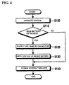
- Fig. 4 is a flow diagram illustrating a method for performing a stable system turn-off when the main battery is abruptly detached from a system, according to an embodiment of the present invention.
- Fig. 1 is a block diagram of a power supply circuit according to an embodiment of the present invention.
- a battery detection switch 100 detects whether a main battery 110 is detached from a PDA system and then informs a CPU 102 of a detection result. That is, if the main battery 110 is attached to the PDA system, the battery detection switch 100 transmits a signal 'ATTACHED' to the CPU 102. If the main battery 110 is detached from the system, the battery detection switch 100 transmits a signal 'DETACHED' to the CPU 102.
- the CPU 102 transmits a refresh command to a device for maintaining data, such as an SDRAM 104.
- the SDRAM 104 stores data that is to be preserved, such as user data, and performs a refresh operation for maintaining such necessary or required data.
- a main power circuit 106 maintains a voltage of the main battery 110 to a regular voltage so as to enable the PDA system to operate stably.
- a large capacitor 108 is provided to temporarily supply backup power to the CPU 102 when the main battery 110 is detached from the system, and generally maintains a voltage higher than a driving voltage Vcc. The large capacitor 108 is available to supply voltage until completion of its discharge.
- the main battery 110 is the primary power source device, which supplies a driving voltage to the system through the main power circuit 106.
- a backup battery 116 is a backup power source device, which supplies power to the CPU 102 and the SDRAM 104 when the main battery 110 is detached from the system.
- the present invention enables the system to be stably turned off according to the CPU 102's control signals for operation of a first switch 112 and a second switch 114.
- Fig. 2 is a block diagram of a power supply circuit for stably supplying power to the system according to an embodiment of the present invention.
- the PDA system performs a stable operation while the main battery 110 is normally maintained.
- the battery detection switch 100 transmits a battery detection signal to the CPU 102 when the main battery 110 is normally maintained.
- the battery detection switch 100 is constructed to be physically pressed when a user moves, i.e. unlocks, a lock device for the main battery 110, to thereby be able to sense that the main battery is about to be attached to or detached from the system.
- the CPU 102 Upon reception of the battery detection signal from the battery detection switch 100, the CPU 102 closes the first switch 112 and opens the second switch 114. Accordingly, the main battery 110 supplies power to the system.
- the main battery 110 supplies power to the CPU 102 and the SDRAM 104 through the main power circuit 106 and the first switch 112.
- the main power circuit 106 maintains a voltage of the main battery 110 regularly to thereby supply power to the system.
- the large capacitor 108 is connected in parallel to the main battery 110 to thereby be charged by the main battery 110.
- the backup battery 116 cannot supply power to the system according due to the second switch 114 being in an open position.
- the power supply circuit maintains the first switch 112 in a closed position and the second switch 114 in an opened position.
- Fig. 3 is a block diagram of a power supply circuit for enabling a stable system turn-off when a main battery is abruptly detached, according to an embodiment of the present invention.
- the power supply circuit of the present invention enables the PDA system to be stably turned off when the main battery 110 is abruptly detached from the system. For this, when a user abruptly detaches the main battery 110 from the system (or when the main battery 110 is detached from the system by the user's carelessness) during the operation of the system, the battery detection switch 100 detects the abrupt detachment of the main battery 110 to then transmit a signal 'ABRUPTLY DETACHED' to the CPU 102.
- the CPU 102 Upon receiving the signal 'ABRUPTLY DETACHED' from the battery detection switch 100, the CPU 102 performs a command for opening the first switch 112 and closing the second switch 114.
- the first switch 112 is opened and the second switch 114 is closed, whereby the main power circuit 106 does not operate and the backup battery 116 supplies power to the CPU 102 and the SDRAM 104.
- the CPU 102 can operate continuously and user data stored in the SDRAM 104 can be preserved. That is, the CPU 102 performs a refresh command for the SDRAM 104 to store necessary data, and the SDRAM 104 stores the necessary data according to the refresh command.
- the refresh command is performed only by the backup battery 116, the power consumption of the backup battery 116 becomes great, and, in some cases, the CPU 102 cannot perform the refresh command owing to time consumption caused by the switching operations of the first and second switch 112 and 114.
- the power supply circuit of the present invention also includes the separate large capacitor 108. As described previously, the large capacitor 108 is connected in parallel to the main battery 110 and is charged by the main battery 100.
- the large capacitor 108 When the main battery 110 is detached from the system and the first switch 112 is opened, the large capacitor 108 provides a driving voltage Vcc to the CPU 102 through the main power circuit 106.
- the provision of the driving voltage Vcc by the large capacitor 108 is instantaneously performed.
- the large capacitor 108 can provide a driving voltage Vcc to the CPU 102.
- the CPU 102 Upon reception of the driving voltage from the large capacitor 108, the CPU 102 performs a refresh command for the SDRAM 104 to store necessary data. Accordingly, the SDRAM 104 stores important data such as user data, whereby the CPU 102 can perform a stable system turn-off.
- the power supply circuit of the present invention provides a driving voltage to the system through the backup battery 116 and the large capacitor 108 by opening the first switch 112 and closing the second switch 114, thereby enabling a stable system turn-off.
- Fig. 4 is a flow diagram illustrating a method for performing a stable system turn-off when the main battery is abruptly detached from the system, according to an embodiment of the present invention.
- a user desiring to turn off the system can turn off the system through a normal system turn-off procedure (S100).
- the CPU 102 performs a refresh command for the SDRAM 104 to store data.
- the system performs a stable system turn-off.
- the present invention also enables a stable system turn-off by using the backup battery 116 and the large capacitor 108 even when the main battery 110 is abruptly detached from the system irrespective of the user's intention.
- the CPU 102 receives a signal 'DETACHED' from the battery detection switch 100, and then opens the first switch 112 and closes the second switch 114.
- the large capacitor 108 provides a driving voltage Vcc to the CPU 102 through the main power circuit 106. If the main battery 110 is detached from the system, the provision of a driving voltage Vcc by the large capacitor 108 is instantaneous (S120).
- the backup battery 116 even if the backup battery 116 cannot provide a driving voltage Vcc to the CPU 102 owing to a switching time, the large capacitor 108 provides a driving voltage to the CPU 102. Accordingly, as the second switch is closed, the backup battery 116 provides power to the CPU 102 and the SDRAM 104 (S130).
- the CPU 102 can operate continuously and user data stored in the SDRAM 104 can be preserved. That is, the CPU 102 issues a refresh command for the SDRAM 104 to store necessary data, and the SDRAM 104 stores the necessary data according to the refresh command, whereby a stable system turn-off is successfully performed (S140).
- the power supply circuit and method of the present invention detects the abrupt detachment of the main battery in advance and performs a stable system turn-off only by a backup power source, thereby making it possible to prevent the loss of user data and the malfunction of the system that may be caused by the abrupt detachment of the main battery.
Landscapes
- Engineering & Computer Science (AREA)
- Power Engineering (AREA)
- Theoretical Computer Science (AREA)
- Business, Economics & Management (AREA)
- Emergency Management (AREA)
- Physics & Mathematics (AREA)
- General Engineering & Computer Science (AREA)
- General Physics & Mathematics (AREA)
- Computer Networks & Wireless Communication (AREA)
- Signal Processing (AREA)
- Power Sources (AREA)
- Techniques For Improving Reliability Of Storages (AREA)
Applications Claiming Priority (1)
| Application Number | Priority Date | Filing Date | Title |
|---|---|---|---|
| KR1020040079312A KR100702362B1 (ko) | 2004-10-06 | 2004-10-06 | 안정적인 시스템 종료를 위한 전원 공급 회로 및 방법 |
Publications (1)
| Publication Number | Publication Date |
|---|---|
| EP1646124A2 true EP1646124A2 (de) | 2006-04-12 |
Family
ID=36125283
Family Applications (1)
| Application Number | Title | Priority Date | Filing Date |
|---|---|---|---|
| EP05021525A Withdrawn EP1646124A2 (de) | 2004-10-06 | 2005-09-30 | Stromversorgungsschaltung und Verfahren zur stabilen Systemabschaltung |
Country Status (4)
| Country | Link |
|---|---|
| US (1) | US20060072268A1 (de) |
| EP (1) | EP1646124A2 (de) |
| KR (1) | KR100702362B1 (de) |
| CN (1) | CN1758501A (de) |
Cited By (2)
| Publication number | Priority date | Publication date | Assignee | Title |
|---|---|---|---|---|
| WO2008049609A1 (en) * | 2006-10-25 | 2008-05-02 | Roche Diagnostics Gmbh | Uninterruptible power supply for a medical appliance |
| WO2012058905A1 (zh) * | 2010-11-02 | 2012-05-10 | 中兴通讯股份有限公司 | 业务处理方法及网络终端 |
Families Citing this family (19)
| Publication number | Priority date | Publication date | Assignee | Title |
|---|---|---|---|---|
| US7737581B2 (en) * | 2005-08-16 | 2010-06-15 | Medtronic Minimed, Inc. | Method and apparatus for predicting end of battery life |
| KR100750197B1 (ko) * | 2006-06-08 | 2007-08-17 | 삼성전자주식회사 | 휴대 단말기에서 전원 공급 제어 장치 및 방법 |
| KR100742116B1 (ko) * | 2006-06-29 | 2007-07-24 | 엘지전자 주식회사 | 이동통신 단말기 및 그의 종료방법 |
| JP5439715B2 (ja) * | 2007-11-20 | 2014-03-12 | 日本電気株式会社 | 携帯端末、制御方法、プログラム、及び記録媒体 |
| WO2010109880A1 (ja) * | 2009-03-26 | 2010-09-30 | 京セラ株式会社 | 無線通信端末 |
| US9019067B2 (en) * | 2010-12-30 | 2015-04-28 | Sargent Manufacturing Company | Electronic lock with power failure control circuit |
| WO2012102696A1 (en) * | 2011-01-24 | 2012-08-02 | Hewlett-Packard Development Company L.P. | Fault detection |
| KR101843983B1 (ko) * | 2011-06-14 | 2018-03-30 | 삼성전자주식회사 | 휴대 단말기에서 배터리를 교체하는 장치 및 방법 |
| CN103002115A (zh) * | 2011-09-16 | 2013-03-27 | 中兴通讯股份有限公司 | 一种通讯装置及异常掉电处理方法 |
| KR20140104617A (ko) * | 2013-02-20 | 2014-08-29 | 삼성전자주식회사 | 서든 파워 오프 가능성 정보를 사용하는 모바일 장치 및 그것의 동작 방법 |
| US9641220B2 (en) * | 2014-02-28 | 2017-05-02 | Dgi Creations, Llc | Alternative power source for network protector relay |
| WO2015170545A1 (ja) * | 2014-05-07 | 2015-11-12 | 日本碍子株式会社 | 全固体電池を用いた揮発性メモリ用バックアップシステム |
| KR102359979B1 (ko) * | 2015-11-16 | 2022-02-08 | 삼성전자주식회사 | 솔리드 스테이트 드라이브 장치 및 이를 포함하는 저장 시스템 |
| US20170155275A1 (en) * | 2015-11-30 | 2017-06-01 | Airwire Technologies | Backup circuitry for providing power |
| JP6732831B2 (ja) * | 2018-04-10 | 2020-07-29 | 矢崎総業株式会社 | 電源供給装置 |
| CN111130205B (zh) * | 2018-10-30 | 2021-05-28 | 深圳中瀚云科技股份有限公司 | 备份供电系统及其控制方法、存储介质 |
| JP7255249B2 (ja) * | 2019-03-12 | 2023-04-11 | 富士通株式会社 | 電源回路及び電子装置 |
| CN113316528B (zh) * | 2020-05-20 | 2024-06-28 | 深圳元戎启行科技有限公司 | 用于车辆的冗余电源电路及自动驾驶控制装置 |
| CN115441740A (zh) * | 2021-06-02 | 2022-12-06 | 超聚变数字技术有限公司 | 供电模组及电子设备 |
Family Cites Families (14)
| Publication number | Priority date | Publication date | Assignee | Title |
|---|---|---|---|---|
| US4638175A (en) * | 1984-07-03 | 1987-01-20 | United Technologies Corporation | Electric power distribution and load transfer system |
| JP2594181B2 (ja) * | 1991-02-04 | 1997-03-26 | シャープ株式会社 | 携帯用電子機器 |
| JPH0621866A (ja) * | 1992-07-03 | 1994-01-28 | Hitachi Ltd | 蓄電池内蔵移動無線通信機 |
| JP2708374B2 (ja) * | 1994-07-26 | 1998-02-04 | インターナショナル・ビジネス・マシーンズ・コーポレイション | コンピュータ用バッテリ接続装置及びバッテリの切換方法 |
| US5939799A (en) * | 1997-07-16 | 1999-08-17 | Storage Technology Corporation | Uninterruptible power supply with an automatic transfer switch |
| KR100528457B1 (ko) * | 1998-10-09 | 2006-01-27 | 삼성전자주식회사 | 배터리를 사용하는 휴대용 전자 장치의 전원 제어 회로 |
| KR20010091481A (ko) * | 2000-03-15 | 2001-10-23 | 김종혁 | 이동통신 단말기의 통화 제어장치 및 그 방법 |
| US7089344B1 (en) * | 2000-06-09 | 2006-08-08 | Motorola, Inc. | Integrated processor platform supporting wireless handheld multi-media devices |
| US7061139B2 (en) * | 2001-02-13 | 2006-06-13 | Utc Fuel Cells, Llc | System for providing assured power to a critical load |
| US20030197428A1 (en) * | 2002-04-05 | 2003-10-23 | Hatton Thomas E. | Power processor |
| KR20030094944A (ko) * | 2002-06-10 | 2003-12-18 | 안기철 | 보조전원을 가진 이동전화기 및 그의 전원공급방법 |
| US6710578B1 (en) * | 2002-08-27 | 2004-03-23 | Motorola, Inc. | Power resource management in a portable communication device |
| US7129599B2 (en) * | 2002-10-15 | 2006-10-31 | Soft Switching Technologies Corporation | Dual feed power supply systems with enhanced power quality |
| KR100523899B1 (ko) * | 2003-05-09 | 2005-10-25 | 주식회사 팬택 | 보조 전원을 구비하는 이동통신단말기 |
-
2004
- 2004-10-06 KR KR1020040079312A patent/KR100702362B1/ko not_active Expired - Fee Related
-
2005
- 2005-09-28 CN CNA2005101056170A patent/CN1758501A/zh active Pending
- 2005-09-30 EP EP05021525A patent/EP1646124A2/de not_active Withdrawn
- 2005-09-30 US US11/241,476 patent/US20060072268A1/en not_active Abandoned
Cited By (5)
| Publication number | Priority date | Publication date | Assignee | Title |
|---|---|---|---|---|
| WO2008049609A1 (en) * | 2006-10-25 | 2008-05-02 | Roche Diagnostics Gmbh | Uninterruptible power supply for a medical appliance |
| US8030802B2 (en) | 2006-10-25 | 2011-10-04 | Roche Diagnostics International Ag | Uninterruptible power supply for a medical appliance |
| US8836176B2 (en) | 2006-10-25 | 2014-09-16 | Roche Diagnostics International Ag | Uninterruptible power supply for a medical appliance |
| WO2012058905A1 (zh) * | 2010-11-02 | 2012-05-10 | 中兴通讯股份有限公司 | 业务处理方法及网络终端 |
| CN102457398A (zh) * | 2010-11-02 | 2012-05-16 | 中兴通讯股份有限公司 | 网络终端处理方法及网络终端 |
Also Published As
| Publication number | Publication date |
|---|---|
| KR20060030528A (ko) | 2006-04-11 |
| US20060072268A1 (en) | 2006-04-06 |
| KR100702362B1 (ko) | 2007-04-02 |
| CN1758501A (zh) | 2006-04-12 |
Similar Documents
| Publication | Publication Date | Title |
|---|---|---|
| EP1646124A2 (de) | Stromversorgungsschaltung und Verfahren zur stabilen Systemabschaltung | |
| US8532716B2 (en) | Electric power control method and mobile device adapted thereto | |
| US7716505B2 (en) | Power control methods for a portable electronic device | |
| FI101669B (fi) | Monipalvelumatkaviestin | |
| US6457134B1 (en) | Portable computer with differentiated time-out feature | |
| EP2824895B1 (de) | Informationssicherungsverfahren und -vorrichtung, mobiles endgerät | |
| US20060090088A1 (en) | Method and apparatus for managing power of portable information device | |
| KR19990044502A (ko) | 개인통신 단말기 | |
| US7454231B2 (en) | Portable cellular phone | |
| CN107948798B (zh) | 充电盒、无线设备以及无线耳机 | |
| US20080010514A1 (en) | Backup power supply and desktop computer and method for protecting the data thereof | |
| WO2011017877A1 (zh) | 一种移动终端及其显示关键信息的方法 | |
| US7082288B2 (en) | Cellular phone, and data protection method and program thereof | |
| JP3963470B2 (ja) | 携帯端末および当該端末の制御方法 | |
| CN109936197A (zh) | 一种放电方法、移动电源及计算机存储介质 | |
| CN103841291A (zh) | 信息处理设备 | |
| KR100605991B1 (ko) | 휴대 단말의 사용자 데이터 보존 방법과 그 회로 | |
| US20150185800A1 (en) | Computer input device power savings | |
| CN112449330A (zh) | 移动终端通信方法、移动终端和存储介质 | |
| CN107272864B (zh) | 一种复位电路、电池及电子设备 | |
| CN106534524A (zh) | 一种关机显示方法及终端 | |
| KR101134874B1 (ko) | 휴대용 단말기의 터치패드 제어장치 및 방법 | |
| JPH113292A (ja) | データバックアップ方法およびシステム | |
| CN113541291B (zh) | 一种具有电池切换功能的终端 | |
| CN108509310B (zh) | 一种防止智能终端自动掉电的方法、存储介质及智能终端 |
Legal Events
| Date | Code | Title | Description |
|---|---|---|---|
| PUAI | Public reference made under article 153(3) epc to a published international application that has entered the european phase |
Free format text: ORIGINAL CODE: 0009012 |
|
| AK | Designated contracting states |
Kind code of ref document: A2 Designated state(s): AT BE BG CH CY CZ DE DK EE ES FI FR GB GR HU IE IS IT LI LT LU LV MC NL PL PT RO SE SI SK TR |
|
| AX | Request for extension of the european patent |
Extension state: AL BA HR MK YU |
|
| 17P | Request for examination filed |
Effective date: 20060731 |
|
| STAA | Information on the status of an ep patent application or granted ep patent |
Free format text: STATUS: THE APPLICATION HAS BEEN WITHDRAWN |
|
| 18W | Application withdrawn |
Effective date: 20080818 |