EP1538371B1 - Steuerung für die Überbrückungskupplung eines Momentwandlers - Google Patents
Steuerung für die Überbrückungskupplung eines Momentwandlers Download PDFInfo
- Publication number
- EP1538371B1 EP1538371B1 EP04021819A EP04021819A EP1538371B1 EP 1538371 B1 EP1538371 B1 EP 1538371B1 EP 04021819 A EP04021819 A EP 04021819A EP 04021819 A EP04021819 A EP 04021819A EP 1538371 B1 EP1538371 B1 EP 1538371B1
- Authority
- EP
- European Patent Office
- Prior art keywords
- rotation speed
- relative rotation
- lockup
- value
- controller
- Prior art date
- Legal status (The legal status is an assumption and is not a legal conclusion. Google has not performed a legal analysis and makes no representation as to the accuracy of the status listed.)
- Expired - Lifetime
Links
Images





Classifications
-
- F—MECHANICAL ENGINEERING; LIGHTING; HEATING; WEAPONS; BLASTING
- F16—ENGINEERING ELEMENTS AND UNITS; GENERAL MEASURES FOR PRODUCING AND MAINTAINING EFFECTIVE FUNCTIONING OF MACHINES OR INSTALLATIONS; THERMAL INSULATION IN GENERAL
- F16H—GEARING
- F16H61/00—Control functions within control units of change-speed- or reversing-gearings for conveying rotary motion ; Control of exclusively fluid gearing, friction gearing, gearings with endless flexible members or other particular types of gearing
- F16H61/14—Control of torque converter lock-up clutches
- F16H61/143—Control of torque converter lock-up clutches using electric control means
-
- F—MECHANICAL ENGINEERING; LIGHTING; HEATING; WEAPONS; BLASTING
- F16—ENGINEERING ELEMENTS AND UNITS; GENERAL MEASURES FOR PRODUCING AND MAINTAINING EFFECTIVE FUNCTIONING OF MACHINES OR INSTALLATIONS; THERMAL INSULATION IN GENERAL
- F16H—GEARING
- F16H59/00—Control inputs to control units of change-speed- or reversing-gearings for conveying rotary motion
- F16H59/36—Inputs being a function of speed
- F16H59/46—Inputs being a function of speed dependent on a comparison between speeds
- F16H2059/465—Detecting slip, e.g. clutch slip ratio
- F16H2059/467—Detecting slip, e.g. clutch slip ratio of torque converter
-
- F—MECHANICAL ENGINEERING; LIGHTING; HEATING; WEAPONS; BLASTING
- F16—ENGINEERING ELEMENTS AND UNITS; GENERAL MEASURES FOR PRODUCING AND MAINTAINING EFFECTIVE FUNCTIONING OF MACHINES OR INSTALLATIONS; THERMAL INSULATION IN GENERAL
- F16H—GEARING
- F16H61/00—Control functions within control units of change-speed- or reversing-gearings for conveying rotary motion ; Control of exclusively fluid gearing, friction gearing, gearings with endless flexible members or other particular types of gearing
- F16H61/14—Control of torque converter lock-up clutches
- F16H61/143—Control of torque converter lock-up clutches using electric control means
- F16H2061/145—Control of torque converter lock-up clutches using electric control means for controlling slip, e.g. approaching target slip value
-
- F—MECHANICAL ENGINEERING; LIGHTING; HEATING; WEAPONS; BLASTING
- F16—ENGINEERING ELEMENTS AND UNITS; GENERAL MEASURES FOR PRODUCING AND MAINTAINING EFFECTIVE FUNCTIONING OF MACHINES OR INSTALLATIONS; THERMAL INSULATION IN GENERAL
- F16H—GEARING
- F16H61/00—Control functions within control units of change-speed- or reversing-gearings for conveying rotary motion ; Control of exclusively fluid gearing, friction gearing, gearings with endless flexible members or other particular types of gearing
- F16H61/14—Control of torque converter lock-up clutches
- F16H61/143—Control of torque converter lock-up clutches using electric control means
- F16H2061/146—Control of torque converter lock-up clutches using electric control means for smoothing gear shift shock
Definitions
- This invention relates to control of a tightening force of a lockup clutch associated with a torque converter for a vehicle.
- a torque converter installed between an engine and an automatic transmission of a vehicle transmits torque between a pump impeller and a turbine runner via a fluid. Since the relative rotation between the pump impeller and the turbine runner increases the fuel consumption of the engine, it is preferable to directly connect the pump impeller and the turbine runner soon after the vehicle is started up. A lockup clutch is provided to accomplish this purpose. Such a torque transmission is disclosed in the closest prior art document US 6 066 072 A .
- a torque converter provided with a lockup clutch
- switching between a converter mode in which the torque is transmitted via a fluid and a lockup mode in which the torque is transmitted via the lockup clutch is performed via a slip mode in which a slip in the lockup clutch is allowed such that a part of the torque is transmitted via the fluid while the other part of the torque is transmitted via the lockup clutch.
- United States Patent serial No. 6,066,072 discloses a two-degree-of-freedom control device which determines a relative rotation speed command value between the pump impeller and the turbine runner by using a feedforward command value based on a reference model thereof and a feedback command value based on a difference between the target relative rotation speed and the real relative rotation speed.
- the device is provided with a feedback compensator and a pre-processing unit comprising a feedforward compensator so as to realize a dynamic characteristic of a reference model.
- the feedback compensator ensures control stability while the feedforward compensator ensures good control response.
- These compensators can be designed independently of each other.
- the target relative rotation speed and the characteristic of the reference model are set according to the required specifications determined during the design stage of the vehicle according to assumed running states of the vehicle. For example, when the vehicle running speed is very low, it is preferable to converge the relative rotation speed promptly to the target relative rotation speed to prevent a muffled sound from being transmitted to the vehicle interior. On the other hand, at a timing immediately after the start of tightening operation of the lockup clutch for shifting from the converter mode to the lockup mode, it is preferable to converge the relative rotation speed smoothly to the target relative rotation speed such that the driver of the vehicle does not notice the lockup action.
- the control device satisfies the different requirements by varying a filter constant of the reference model.
- a filter constant of the reference model For example, when the pre-processing unit is provided with a reference model of a first-order delay, it is accomplished by varying the time constant for the first-order delay.
- the relative rotation speed between the pump impeller and the turbine runner is controlled through control of the hydraulic pressure applied to the lockup clutch as tightening force.
- this invention provides a lockup control device for a lockup clutch of a torque converter for a vehicle.
- the torque converter comprises a pump impeller connected to an engine and a turbine runner connected to an automatic transmission, and transmits a torque between the pump impeller and the turbine runner via a fluid and the lockup clutch according to a tightening force of the lockup clutch.
- the device comprises a mechanism which regulates the tightening force, a sensor which detects a rotation speed of the pump impeller, a sensor which detects a rotation speed of the turbine runner, a sensor which detects a running condition of the engine, and a programmable controller that controls the mechanism.
- the controller is programmed to calculate a real relative rotation speed of the pump impeller and the turbine runner from the rotation speed of the pump impeller and the rotation speed of the turbine runner, determine a target relative rotation speed based on the running condition of the engine, perform feedback control of the mechanism based on a difference between the target relative rotation speed and the real relative rotation speed to cause the difference to decrease, perform feedforward control of the mechanism in combination with the feedback control, determine whether or not a variation in a feedforward control amount applied to the mechanism by the feedforward control has exceeded a predetermined value, and correct a feedback control amount applied to the mechanism by the feedback control in a direction to moderate an effect of the variation, when the variation has exceeded the predetermined value.
- This invention also provide a lockup control method of the lockup clutch of a torque converter for a vehicle.
- the torque converter comprises a pump impeller connected to an engine and a turbine runner connected to an automatic transmission, and transmits a torque between the pump impeller and the turbine runner via a fluid and via the lockup clutch according to a tightening force of the lockup clutch supplied from a tightening force regulating mechanism.
- the method comprises determining a rotation speed of the pump impeller, the rotation speed of the pump impeller being equal to an engine rotation speed, determining a rotation speed of the turbine runner, determining a running condition of the engine, calculating a real relative rotation speed of the pump impeller and the turbine runner from the rotation speed of the pump impeller and the rotation speed of the turbine runner, determining a target relative rotation speed based on the running condition of the engine, performing feedback control of the regulating mechanism based on a difference between the target relative rotation speed and the real relative rotation speed to cause the difference to decrease, performing feedforward control of the regulating mechanism in combination with the feedback control, determining whether or not a variation in a feedforward control amount applied to the mechanism by the feedforward control has exceeded a predetermined value, and correcting a feedback control amount applied to the regulating mechanism by the feedback control in a direction to moderate an effect of the variation, when the variation has exceeded the predetermined value.
- FIG. 1 is a schematic diagram of a power train of a vehicle provided with a lockup clutch to which this invention is applied.
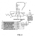
- FIG. 2 is a schematic diagram of a lockup control device according to this invention.
- FIG. 3 is a block diagram describing control functions of a controller according to this invention.
- FIG. 4 is a flowchart describing a routine for correcting an output ⁇ SLPC1 of a feedback compensator performed by the controller.
- FIG. 5 is a diagram showing the characteristics of a map of a predetermined threshold value DSPFF, which is stored by the controller.
- FIG. 6 is a diagram showing the characteristics of a map of a relative rotation gain g SLPC , which is stored by the controller.
- FIG. 7 is a diagram showing the characteristics of a map of an engine output torque t ESC , which is stored by the controller.
- FIG. 8 is a diagram showing the characteristics of a map of a target lockup clutch tightening capacity t LUC , which is stored by the controller.
- FIG. 9 is a diagram showing the characteristics of a time constant Tt applied in the calculation of an output ⁇ SLPTC2 of a feedforward compensator according to a second embodiment of this invention.
- FIG. 10 is a flowchart describing a routine for setting a correction request flag fADJREQ performed a the controller according to the second embodiment of this invention.
- FIG. 11 is a flowchart describing a routine for calculating an output ⁇ SLPC1 of a feedback compensator performed by the controller according to the second embodiment of this invention.
- FIGs. 12A-12F are timing charts showing the result of an execution of the routines of FIGs. 10 and 11 by the controller according to the second embodiment of this invention.
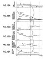
- FIGs. 13A-13F are similar to FIGs. 12A-12F , but show a case where a step S18 is omitted from the routine of FIG. 10 .
- FIGs. 14A-14F are similar to FIGs. 12A-12F , but show a specific effect of the execution of the step S18 in the routine of FIG. 10 .
- FIGs. 15A-15F are similar to FIGs. 12A-12F , but show a prior art example.
- a multi-cylinder engine 21 for a vehicle is connected to an automatic transmission 23 via a torque converter 1, and an output torque of the automatic transmission 23 is transmitted to a driving wheel 25 via a differential 24.
- the automatic transmission 23 is constituted by a continuously variable transmission.
- the torque converter 1 is provided with a pump impeller 1a driven by the engine 21, a turbine runner 1b joined to the input shaft of the automatic transmission 23, and a lockup clutch 2 which directly connects the pump impeller 1a and turbine runner 1b.
- the tightening force of the lockup clutch 2 is determined by a differential pressure ( PA-PR ) between an application pressure PA and a release pressure PR.
- the lockup clutch 2 When the application pressure PA is lower than the release pressure PR , the lockup clutch 2 enters an unlocked state, and the pump impeller 1a and turbine runner 1b rotate according to the torque transmission function of the fluid interposed therebetween.
- the pump impeller 1a and turbine runner 1b transmit a torque according to the differential pressure ( PA-PR ) while performing relative rotation.
- the torque converter 1 delivers torque by two pathways, i.e., by the fluid and by mechanical transmission by the lockup clutch 2.
- the engine output torque is equal to the total torque.
- the transmission torque of the lockup clutch 2 is hereinafter expressed as the torque capacity of the lockup clutch 2.
- the torque capacity of the lockup clutch 2 is controlled by a control device comprising a slip control valve 3, a solenoid valve 4, a controller 5 and a gear ratio calculation unit 26.
- the control valve 3 supplies the application pressure PA and release pressure PR to the lockup clutch 2 according to a signal pressure Ps input from the solenoid valve 4.
- the control valve 3 varies the pressure difference between the application pressure PA and release pressure PR , i.e., the tightening pressure of the lockup clutch 2 according to the signal pressure Ps .
- the solenoid valve 4 adjusts the pump pressure Pp supplied from the oil pressure source to the signal pressure Ps using a solenoid which responds to a duty signal S DUTY .
- the duty signal S DUTY is outputted from the controller 5.
- the controller 5 comprises a microcomputer provided with a central processing unit (CPU), read-only memory (ROM), random access memory (RAM) and input/output interface (I/O interface).
- the controller may also comprise plural microcomputers.
- the controller 5 controls the differential pressure ( PA-PR ) applied to the lockup clutch 2 according to whether the running state of the vehicle corresponds to a converter region, a slip region or a lockup region. In the first half of the slip region, open loop control of the differential pressure ( PA-PR ) is performed, and in the second half of the slip region, feedback /feedforward control of the differential pressure ( PA-PR ) is performed.
- the controller 5 controls the differential pressure ( PA-PR ) by outputting of the duty signal S DUTY to the solenoid valve 4.
- the gear ratio calculation unit 26 calculates a real gear ratio ip of the automatic transmission 23 from the rotation speed ⁇ TR of the turbine runner 1b and the vehicle speed VSP, and inputs it to the controller 5.
- the gear ratio calculation unit 26 comprises the same microcomputer as that of the controller 5.
- the controller 5 and the gear ratio calculation unit 26 may also comprise the same microcomputer.
- a target relative rotation speed calculating unit 100 determines a target relative rotation speed ⁇ SLPT of the pump impeller 1a and turbine runner 1b based on the vehicle speed VSP, throttle opening TVO, gear ratio ip and oil temperature T ATF .
- the target relative rotation speed ⁇ SLPT is the relative rotation speed for obtaining a minimum fluctuation in the engine output torque due to scatter in the combustion of the engine 21 and a minimum pulsation noise emitted by the drive train.
- the target relative rotation speed ⁇ SLPT is preset by experiment according to the above parameters.
- a real relative rotation computing unit 103 computes a real relative rotation speed ⁇ SLPR of the torque converter 1 by subtracting the rotation speed ⁇ TR of the turbine runner 1b from the rotation speed ⁇ IR of the pump impeller 1a.
- the rotation speed of the pump impeller 1a is equivalent to the rotation speed of the engine 21 and the rotation speed of the turbine runner 1b is equivalent to the input rotation speed of the automatic transmission 23.
- a pre-processing unit 101 calculates target relative rotation speed correction values ⁇ SLPTC1 and ⁇ SLPTC2 by processing the target relative rotation speed ⁇ SLPT with compensation filters so that the target relative rotation speed displays the intended response.
- the pre-processing unit 101 comprises a pre-processing compensator 101A and a feedforward compensator 101B.
- the pre-processing compensator 101A calculates a first target relative rotation speed correction value ⁇ SLPTC1 from Equation (1) below.
- ⁇ SLPTC ⁇ 1 G R s ⁇ ⁇ SLPT t
- Equation (1) corresponds to a first-order delay processing.
- the feedforward compensator 101B calculates a second target relative rotation speed correction value ⁇ SLPTC2 from Equation (2) below.
- ⁇ SLPTC ⁇ 2 G M s ⁇ ⁇ SLPT t
- G M ( s ) G R s P s ,
- G M ( s ) transfer function of feedforward compensator
- Equation (3) the transfer function G M ( s ) of the feedforward compensator can be expressed by Equation (3) below.
- G M s 1 + Tp ⁇ s 1 + Tt ⁇ s
- a filter constant setting unit 111 sets the time constant Tp and the time constant Tt.
- the control system according to this invention is a two-degree-of-freedom control system, so the time constant Tt of the reference model is set according to the running state of the vehicle such that preferred response is realized, and the time constant Tp of the relative rotation model is set according to the characteristic of the relative rotation model.
- a rotation deviation computing unit 102 calculates the deviation ⁇ SLPER between the first target relative rotation speed ⁇ SLPTC1 and the real relative rotation speed ⁇ SLPR as follows.
- ⁇ SLPER ⁇ SLPTC ⁇ 1 - ⁇ SLPR
- a feedback compensating unit 104 comprises a feedback compensator that calculates a first relative rotation speed command value ⁇ SLPC1 on the basis of this deviation ⁇ SLPER using Equation (5) below which represents proportional/integral feedback control.
- G CNT ( s ) transfer function of feedback compensator
- K p proportional gain
- K i integral gain
- s differential operator.
- the feedback compensating unit 104 calculates a relative rotation speed command value ⁇ SLPC by adding the second target relative rotation speed correction value ⁇ SLPTC2 to the first relative rotation speed command value ⁇ SLPC1 in Equation (6) below.
- ⁇ SLPC ⁇ SLPC ⁇ 1 + ⁇ SLPTC ⁇ 2
- a relative rotation gain computing unit 106 uses the rotation speed ⁇ TR of the turbine runner 1b to calculate the relative rotation gain g SLPC by referring to a map having the characteristics shown in FIG. 6 . This map is prestored in the memory (ROM) of the controller 5.
- a target fluid transmission torque computing unit 105 calculates a target converter transmission torque t CNVC corresponding to the relative rotation speed command value ⁇ SLPC using the relative rotation gain g SLPC using Equation (7) below.
- t CNVC ⁇ SLPC g SLPC
- An engine output torque estimating unit 108 estimates an engine output torque t ES of the engine 21 by referring to a map having the characteristics shown in FIG. 7 based on the engine rotation speed Ne and throttle opening TVO. This map is prestored in the memory (ROM) of the controller 5.
- Equation (8) This value is filter processed by Equation (8) below using a time constant T ED taking account of a first-order delay of the engine dynamics to obtain an engine torque estimated value t EH .
- t EH 1 1 + T ED ⁇ s ⁇ t ES
- a lockup clutch tightening pressure command value computing unit 109 calculates a lockup clutch tightening pressure command value P LUC required to achieve the target lockup clutch tightening capacity t LUC by referring to a map having the characteristics shown in FIG. 8 . This map is drawn up in advance on the basis of experimental results regarding the relation between the tightening pressure and tightening capacity of the lockup clutch 2, and is prestored in the memory (ROM) of the controller 5.
- a solenoid drive signal computing unit 110 calculates a lockup duty based on the lockup clutch tightening pressure command value P LUC , and outputs a corresponding duty signal S DUTY to the solenoid valve 4
- This routine is executed by the controller 5 at intervals of ten milliseconds when the engine 21 is operating.
- a variation ⁇ SLPADJ ⁇ SLPTC ⁇ 2 - SLPTC ⁇ 2 _M
- SLPTC2_M second target relative rotation speed correction value ⁇ SLPTC2 that was calculated by the feedforward compensator 101B of the pre-processing unit 101 on the immediately preceding occasion when the routine was performed.
- the controller 5 calculates the first relative rotation speed command value ⁇ SLPC1 using the function of the feedback compensator in the feedback compensating unit 104, i.e., calculating ⁇ SLPC1 from the deviation ⁇ SLPER using Equation (5). Since the value calculated in this step may be further corrected later, the value is memorized as a candidate value ⁇ SLPC3 .
- the controller compares an absolute value of the variation ⁇ SLPADJ with that of a predetermined threshold value DSLPFF.
- the threshold value DSLPFF is a value for determining if the output ⁇ SLPTC2 of the feedforward compensator 101B will cause the lockup clutch 2 to generate a shock.
- the predetermined threshold value DSPFF varies according to the throttle valve opening TVO as shown in FIG. 5 .
- the controller 5 prestores a map defining the relation as shown in the figure and, in the step S2, it refers to the map from the throttle valve opening TVO to determine the predetermined value DSPFF.
- the variation ⁇ SLPADJ takes a negative value.
- the value DSPFF in FIG. 5 also takes a negative value.
- the comparison in the step S2 is performed using absolute values in order to compare the magnitude of the variation ⁇ SLPADJ and the magnitude of the predetermined value DSPFF.
- the controller 5 performs the processing of a step S4.
- the controller 5 performs the processing of a step S5.
- the controller 5 calculates the first relative rotation speed command value ⁇ SLPC1 using Equation (11) below.
- ⁇ SLPC ⁇ 1 ⁇ SLPC ⁇ 3 - ⁇ SLPADJ
- the controller 5 sets the first relative rotation speed command value ⁇ SLPC1 to equal the candidate value ⁇ SLPC3 calculated in the step S3.
- step S4 or step S5 the controller 5 terminates the routine.
- FIGs. 9-11 and FIGs. 12A-12F , 13A-13F , 14A-14F a second embodiment of this invention will be described.
- different values T1 and T2 are selectively applied for the time constant Tt of the reference model.
- the time constant Tt is preferably changed over from T1 to T2 , which is smaller than T1.
- Equations (2) and (3) when the time constant Tt varies in a stepwise fashion, the output ⁇ SLPTC2 of the feedforward compensator 101B varies in a similar fashion.
- the controller 5 corrects the output ⁇ SLPC1 of the feedback compensator in the feedback compensating unit 104 when the time constant Tt has been switched over from the value T1 to the value T2, or vice versa.
- a routine shown in FIG. 10 determines whether or not correction of the output ⁇ SLPC1 of the feedback compensator in the feedback compensating unit 104 is required.
- a routine shown in FIG. 11 corrects the output ⁇ SLPC1 of the feedback compensator according to the determination result of the routine of FIG. 10 .
- the routines are executed consecutively by the feedback compensating unit 104 in the controller 5 at intervals of ten milliseconds when the engine 21 is operating.
- a deviation ⁇ SLP between the target relative rotation speed ⁇ SLPT determined by the target relative rotation speed calculating unit 100 and the real relative rotation speed ⁇ SLPR computed by the real relative rotation computing unit 103 according to Equation (12) below.
- ⁇ ⁇ ⁇ SLP ⁇ SLPTC ⁇ 1 - ⁇ SLPR
- the controller 5 compares the deviation ⁇ SLP with a predetermined value DSLP1.
- the predetermined value DSLP1 is a value for determining which of the values T1 or T2 be applied for the time constant Tt of the reference model according to the magnitude of the deviation ⁇ SLP .
- the controller 5 sets the time constant Tt of the reference model to the larger value T1 in a step S13.
- the deviation region where ⁇ SLP is greater than the predetermined value DSLP1 is named as region A.
- the controller 5 sets the time constant Tt of the reference model to the smaller value T2 in a step S15.
- the deviation region where ⁇ SLP is not greater than the predetermined value DSLP1 is named as region B.
- the controller 5 determines in a step S14 whether or not the deviation ⁇ SLP(n-1) calculated on the immediately preceding occasion when the routine was executed was also a value in the region A.
- the controller 5 determines in a step S16 whether or not the deviation ⁇ SLP(n-1) calculated on the immediately preceding occasion when the routine was executed was also a value in the region B
- step S17 the controller 5 resets a correction request flag fADJREQ to zero.
- the controller 5 determines whether or not the time constant Tt of the reference model is greater than the time constant Tp of the relative rotation model in a step S18. When the time constant Tt is not greater than the time constant Tp, the controller 5 performs the processing of the step S17, i.e., resetting the correction request flag fADJREQ to zero. After the processing in the step S17, the controller 5 terminates the routine.
- the controller 5 sets the correction request flag fADJREQ to unity in a step S19. After the processing in the step S19, the controller 5 terminates the routine.
- the controller 5 reads the second target relative rotation speed correction value ⁇ SPTC2 that was calculated by the feedforward compensator 101B of the pre-processing unit 101 on the immediately preceding occasion when the routine was performed, and memorizes it as a memorized value SLPTC2_M.
- a next step S51 the controller 5 reads the current target relative rotation speed correction value ⁇ SLPTC2 that was calculated by the feedforward compensator 101B of the pre-processing unit 101 on the present occasion when the routine was performed.
- the controller 5 calculates the first relative rotation speed command value ⁇ SLPC1 using the function of the feedback compensator in the feedback compensating unit 104, i.e., calculating ⁇ SLPC1 from the deviation ⁇ SLPER using Equation (5). Since the value calculated in this step may be further corrected later, the value is memorized as a candidate value ⁇ SLPC3 .
- step S53 the controller 5 determines whether or not the correction request flag fADJREQ is at unity.
- the controller 5 determines to correct the candidate value ⁇ SLPC3 before outputting it as the first relative rotation speed command value ⁇ SLPC1 from the feedback compensator in the feedback compensating unit 104, and sets a correction amount to equal the variation ⁇ SLPADJ , which is calculated using Equation (10) described with reference to the first embodiment.
- the controller 5 determines not to apply correction to the candidate value ⁇ SLPC3 and sets the correction amount ⁇ SLPADJ to zero in a step S55.
- the controller 5 calculates the first relative rotation speed command value ⁇ SLPC1 in a step S56 using Equation (13) below.
- ⁇ SLPC ⁇ 1 ⁇ SLPC ⁇ 3 - ⁇ SLPADJ
- the correction amount ⁇ SLPADJ takes a negative value and an increase correction of the first relative rotation speed command value ⁇ SLPC1 is performed in the step S56.
- the controller 5 After the calculation of the first relative rotation speed command value ⁇ SLPC1 , the controller 5 terminates the routine.
- control of the lockup clutch tightening pressure is started at a time t0 such that the real relative rotation speed ⁇ SLPR converges towards the target relative rotation speed ⁇ SLPT .
- the lockup clutch tightening pressure command value P LUC shown in FIG. 12E varies according to the relative rotation speed command value ⁇ SLPC shown in FIG. 12D .
- the relative rotation speed command value ⁇ SLPC is a sum of the output ⁇ SLPTC2 of the feedforward compensator 101B and the output ⁇ SLPC1 of the feedback compensator in the feedback compensating unit 104.
- the routine in FIG. 10 When the routine in FIG. 10 is performed immediately after the time t1, the determination results in the step S16 and the step S18 are both negative, so the correction request flag fADJREQ is set to unity in the step S19.
- the processing in the step S54 is performed and an increase correction of the output ⁇ SLPC1 of the feedback compensator is performed in the step S56.
- the increment in the output ⁇ SLPC1 of the feedback compensator is equal to the decrement ⁇ SLPADJ in the output ⁇ SLPTC2 of the feedforward compensator 101B as shown in FIGs. 12B and 12C .
- the relative rotation speed command value ⁇ SLPC that is the sum of ⁇ SLPTC2 and ⁇ SLPC1 , as well as the lockup clutch tightening pressure command value P LUC , do not show any steep variation despite the change-over of the time constant Tt as shown in FIG. 12D and FIG. 12E respectively.
- no shock occurs when the change-over of the time constant Tt is performed, while ensuring prompt convergence of the real relative rotation speed ⁇ SLPR with the target relative rotation speed ⁇ SLPT .
- the same result may be obtained without correcting the output ⁇ SLPC1 of the feedback compensator, by causing the output ⁇ SLPTC2 of the feedforward compensator 101B to vary smoothly.
- the time constant Tt in order to vary the output ⁇ SLPTC2 smoothly, the time constant Tt must be varied smoothly according to the time constant Tp, which makes the control device much more complicated than the device according to this embodiment.
- FIGs. 15A- 15F show a prior art case where no correction of the output ⁇ SLPC1 of the feedback compensator is performed when the time constant Tt is changed over from T1 to T2.
- FIGs. 13A-13F and FIGs. 14A-14F show a case where control of lockup clutch tightening pressure is performed as in the case of FIGs. 12A-12F , but unlike the case of FIGs. 12A-12F , the value T2 for the time constant Tt is herein set smaller than the time constant Tp as shown in FIGs. 13A and 14A . In this case, the feedforward compensator 101B performs an advance control.
- this invention prevents the correction from being applied to the output ⁇ SLPC1 of the feedback compensator in the feedback compensating unit 104 on the condition that the value T2 be smaller than the time constant Tp. This is accomplished by the step S18 in FIG. 10 .
- the correction request flag fADJREQ is set to zero in the step S17, and therefore the correction amount ⁇ SLPADJ is set to zero in the step S55 such that the correction of the output ⁇ SLPC of the feedback compensator is not performed in the step S56.
- the reference model is constituted by a first-order delay system, and a denominator and a numerator of the transfer function of the feedforward compensator 101B are both first-order functions.
- This invention can however be applied to a compensating system with a transfer function of a higher order, because the gist of this invention is to prevent variation in the output of the feedforward compensator from adversely affecting the lockup clutch tightening pressure and the objective device is not limited by the number of order of the transfer function.
- the parameters required for control are detected using sensors, but this invention can be applied to any device which can perform the claimed control using the claimed parameters regardless of how the parameters are acquired.
- the controller 5 is constituted by a single microcomputer, but may be constituted by plural microcomputers.
Landscapes
- Engineering & Computer Science (AREA)
- General Engineering & Computer Science (AREA)
- Mechanical Engineering (AREA)
- Control Of Fluid Gearings (AREA)
Claims (9)
- Überbrückungs-Steuervorrichtung für eine Überbrückungskupplung (2) eines Drehmomentwandlers (1) für ein Fahrzeug, wobei der Drehmomentwandler (1) ein Pumpenflügelrad (1a), das mit einem Verbrennungsmotor (21) verbunden ist, und ein Turbinenlaufrad (1b), das mit einem Automatikgetriebe (23) verbunden ist, umfasst, und ein Drehmoment zwischen dem Pumpenflügelrad (1a) und dem Turbinenlaufrad (1b) durch ein Fluid und die Überbrückungskupplung (2) gemäß einer Feststellkraft der Überbrückungskupplung (2) überträgt, wobei die Vorrichtung umfasst:eine Einrichtung (3, 4), welche die Feststellkraft reguliert; undeine programmierbare Steuerung (5), die programmiert ist, um:eine relative Ist-Drehzahl des Pumpenflügelrads (1a) und des Turbinenlaufrads (16) aus einer Drehzahl des Pumpenflügelrads (1a) und einer Drehzahl des Turbinenlaufrads (1b) zu berechnen (103);eine relative Ziel-Drehzahl auf der Grundlage einer Betriebsbedingung des Verbrennungsmotors (21) zu bestimmten (100); undeine Regelung der Einrichtung (3, 4) auf der Grundlage einer Differenz zwischen der relativen Ziel-Drehzahl und der relativen Ist-Drehzahl durchzuführen, um zu veranlassen, dass sich die Differenz verringert (104);dadurch gekennzeichnet, dass die Steuerung (5) ferner programmiert ist,um eine Vorwärtsregelung der Einrichtung in Kombination mit der Regelung durchzuführen (101);um zu bestimmen, ob eine Veränderung in einem Vorwärtsregelungsbetrag, der von der Vorwärtsregelung auf die Einrichtung (3, 4) aufgebracht wird, einen vorbestimmten Wert überschritten hat (104, S3, S14, S16); undum einen von der Regelung auf die Einrichtung (3, 4) aufgebrachten Regelungsbetrag in einer Richtung zu korrigieren, um eine Wirkung der Veränderung zu mildern, wenn die Veränderung den vorbestimmten Wert überschritten hat (104, S4, S19, S56).
- Überbrückungs-Steuervorrichtung nach Anspruch 1, wobei die Vorrichtung ferner einen Sensor (7), der die Drehzahl des Pumpenflügelrads (1a) erfasst, einen Sensor (8), der die Drehzahl des Turbinenlaufrads (1b) erfasst, und einen Sensor (8, 9, 10, 11), der die Betriebsbedingung des Motors (21) erfasst, umfasst.
- Überbrückungs-Steuervorrichtung nach Anspruch 1 oder 2, wobei ein Korrekturbetrag des Regelungsbetrags so festgelegt wird, dass er gleich der Veränderung ist.
- Überbrückungs-Steuervorrichtung nach einem der Ansprüche 1 bis 3, wobei die Vorwärtsregelung eine Zwei-Freiheitsgrad-Steuerung ist, die eine Zeitkonstante Tt eines vorab festgelegten Referenzmodells, so dass eine bevorzugte Reaktion realisiert wird, und eine Zeitkonstante Tp eines vorab festgelegten Relativdrehungsmodells gemäß einer Kennlinie der Überbrückungskupplung (2) anwendet.
- Überbrückungs-Steuervorrichtung nach Anspruch 4, wobei die Zeitkonstante Tt des Referenzmodells auf einen ersten Wert gesetzt wird, wenn die Differenz größer als ein vorbestimmter Wert ist (S13), und auf einen zweiten Wert kleiner als der erste Wert gesetzt wird, wenn die Differenz nicht größer als der vorbestimmte Wert ist (S15).
- Überbrückungs-Steuervorrichtung nach Anspruch 5, wobei eine Differenz zwischen dem ersten Wert und dem zweiten Wert so festgelegt ist, dass sie verursacht, dass die Veränderung den vorbestimmten Wert übersteigt, und die Steuerung (5) ferner programmiert ist, um den Regelungsbetrag, der auf die Einrichtung aufgebracht wird, zu korrigieren, wenn die Zeitkonstante Tt des Referenzmodells vom ersten Wert zum zweiten Wert gewechselt ist (S14, S16, S19).
- Überbrückungs-Steuervorrichtung nach Anspruch 6, wobei die Steuerung (5) ferner programmiert ist, um den Regelungsbetrag nicht zu korrigieren, wenn die Zeitkonstante Tt des Referenzmodells kleiner als die Zeitkonstante Tp des Relativdrehungsmodells ist (S17).
- Überbrückungs-Steuervorrichtung nach Anspruch 6, wobei die Steuerung (5) ferner programmiert ist, um den Regelungsbetrag nicht zu korrigieren, wenn die Vorwärtsregelung eine Vorschubsteuerung der Einrichtung durchführt (S18, S19).
- Überbrückungs-Steuerverfahren für eine Überbrückungskupplung (2) eines Drehmomentwandlers (1) für ein Fahrzeug, wobei der Drehmomentwandler (1) ein Pumpenflügelrad (1a), das mit einem Verbrennungsmotor (21) verbunden ist, und ein Turbinenlaufrad (1b), das mit einem Automatikgetriebe (23) verbunden ist, umfasst, und ein Drehmoment zwischen dem Pumpenflügelrad (1a) und dem Turbinenlaufrad (1b) durch ein Fluid und die Überbrückungskupplung (2) gemäß einer Feststellkraft der Überbrückungskupplung (2), die von einer Feststellkraft-Regulierungseinrichtung (3, 4) bereitgestellt wird, überträgt, wobei das Verfahren umfasst:Berechnen einer relativen Ist-Drehzahl des Pumpenflügelrads (1a) und des Turbinenlaufrads (1b) aus einer Drehzahl des Pumpenflügelrads (1a) und einer Drehzahl des Turbinenlaufrads (1b) (103);Bestimmen einer relativen Ziel-Drehzahl auf der Grundlage einer Betriebsbedingung des Verbrennungsmotors (21) (100);Durchführen einer Regelung der Regulierungseinrichtung (3, 4) auf der Grundlage einer Differenz zwischen der relativen Ziel-Drehzahl und der relativen Ist-Drehzahl, um zu veranlassen, dass sich die Differenz verringert (104);gekennzeichnet durchDurchführen einer Vorwärtsregelung der Regulierungseinrichtung (3, 4) in Kombination mit der Regelung (101);Bestimmen, ob eine Veränderung eines durch die Vorwärtsregelung auf die Einrichtung (3, 4) aufgebrachten Vorwärtsregelungsbetrags einen vorbestimmten Wert überschritten hat (104, S3, 514, S16); undKorrigieren eines von der Regelung auf die Regulierungseinrichtung (3, 4) aufgebrachten Regelungsbetrags in einer Richtung, um eine Wirkung der Veränderung zu mildern, wenn die Veränderung den vorbestimmten Wert überschritten hat (104, S4, S19, S56).
Applications Claiming Priority (2)
| Application Number | Priority Date | Filing Date | Title |
|---|---|---|---|
| JP2003407800A JP3890478B2 (ja) | 2003-12-05 | 2003-12-05 | トルクコンバータのスリップ制御装置 |
| JP2003407800 | 2003-12-05 |
Publications (3)
| Publication Number | Publication Date |
|---|---|
| EP1538371A2 EP1538371A2 (de) | 2005-06-08 |
| EP1538371A3 EP1538371A3 (de) | 2005-06-15 |
| EP1538371B1 true EP1538371B1 (de) | 2008-04-23 |
Family
ID=34464029
Family Applications (1)
| Application Number | Title | Priority Date | Filing Date |
|---|---|---|---|
| EP04021819A Expired - Lifetime EP1538371B1 (de) | 2003-12-05 | 2004-09-14 | Steuerung für die Überbrückungskupplung eines Momentwandlers |
Country Status (5)
| Country | Link |
|---|---|
| US (1) | US7085640B2 (de) |
| EP (1) | EP1538371B1 (de) |
| JP (1) | JP3890478B2 (de) |
| CN (1) | CN100362266C (de) |
| DE (1) | DE602004013259T2 (de) |
Families Citing this family (17)
| Publication number | Priority date | Publication date | Assignee | Title |
|---|---|---|---|---|
| DE10355097A1 (de) * | 2003-11-24 | 2005-08-04 | Volkswagen Ag | Drehmomentenübertragungseinrichtung |
| US8401755B2 (en) * | 2008-04-15 | 2013-03-19 | Allison Transmission, Inc. | System and method for detecting lockup clutch on-coming capacity |
| US8812209B2 (en) | 2006-04-15 | 2014-08-19 | Allison Transmission, Inc. | System and method for detecting lockup clutch on-coming capacity |
| US7530924B2 (en) * | 2006-04-17 | 2009-05-12 | Ford Global Technologies, Llc | Torque converter bypass clutch control |
| JP2010502372A (ja) * | 2006-09-08 | 2010-01-28 | シンフォニー メディカル, インコーポレイテッド | 心臓の局所的な異常の治療のための心筋内パターン形成 |
| JP5266843B2 (ja) * | 2008-03-31 | 2013-08-21 | アイシン・エィ・ダブリュ株式会社 | クラッチの制御装置 |
| US8150589B2 (en) | 2008-04-15 | 2012-04-03 | Allison Transmission, Inc. | System and method for managing accumulator effects during engagement of a lockup clutch in a torque converter |
| JP4924620B2 (ja) * | 2009-01-13 | 2012-04-25 | トヨタ自動車株式会社 | 車両の制御装置および制御方法 |
| JP6015503B2 (ja) * | 2012-10-31 | 2016-10-26 | アイシン・エィ・ダブリュ株式会社 | 発進クラッチの制御装置および制御方法 |
| WO2014112606A1 (ja) * | 2013-01-18 | 2014-07-24 | アイシン・エィ・ダブリュ株式会社 | ロックアップクラッチの制御装置および制御方法 |
| JP6350668B2 (ja) * | 2014-09-03 | 2018-07-04 | 日産自動車株式会社 | 車両のロックアップクラッチ制御装置 |
| DE102014222457A1 (de) * | 2014-11-04 | 2016-05-04 | Schaeffler Technologies AG & Co. KG | Verfahren zur Ermittlung eines Übertragungsverhaltens eines Antriebsstrangs |
| JP6123811B2 (ja) * | 2015-01-19 | 2017-05-10 | トヨタ自動車株式会社 | ロックアップクラッチのスリップ制御装置 |
| JP6531627B2 (ja) * | 2015-11-12 | 2019-06-19 | トヨタ自動車株式会社 | ロックアップクラッチの制御装置 |
| US10746291B2 (en) * | 2019-01-17 | 2020-08-18 | Ford Global Technologies, Llc | Engine torque and torque converter bypass clutch slip control during vehicle launch |
| CN110661017B (zh) * | 2019-09-30 | 2020-10-30 | 潍柴动力股份有限公司 | 电池水泵控制方法、电池控制器和电池 |
| JP2025112621A (ja) * | 2024-01-19 | 2025-08-01 | 株式会社エクセディ | 動力伝達装置 |
Family Cites Families (10)
| Publication number | Priority date | Publication date | Assignee | Title |
|---|---|---|---|---|
| US4957194A (en) * | 1987-09-08 | 1990-09-18 | Mazda Motor Corporation | Torque converter slip control device |
| US5627750A (en) * | 1993-12-29 | 1997-05-06 | Toyota Jidosha Kabushiki Kaisha | Clutch slip control device and method of manufacturing the same, clutch slip control method, and vehicle control device |
| DE19504935A1 (de) * | 1994-02-23 | 1995-08-24 | Luk Getriebe Systeme Gmbh | Verfahren zum Steuern eines Drehmomenten-Übertragungssystems |
| US5527238A (en) * | 1995-04-10 | 1996-06-18 | Ford Motor Company | Automatic transmission bypass clutch slip control using nonlinear nverse dynamics |
| JP3191631B2 (ja) * | 1995-08-09 | 2001-07-23 | トヨタ自動車株式会社 | 車両用直結クラッチのスリップ制御装置 |
| JP3240979B2 (ja) * | 1997-11-04 | 2001-12-25 | 日産自動車株式会社 | トルクコンバータのスリップ制御装置 |
| JP3642018B2 (ja) * | 2000-10-27 | 2005-04-27 | 日産自動車株式会社 | トルクコンバータのスリップ制御装置 |
| JP4399989B2 (ja) * | 2001-02-07 | 2010-01-20 | トヨタ自動車株式会社 | 車両の制御装置 |
| JP3912254B2 (ja) * | 2002-10-28 | 2007-05-09 | 日産自動車株式会社 | トルクコンバータのスリップ制御装置 |
| JP3873899B2 (ja) * | 2003-02-13 | 2007-01-31 | 日産自動車株式会社 | トルクコンバータのスリップ制御装置 |
-
2003
- 2003-12-05 JP JP2003407800A patent/JP3890478B2/ja not_active Expired - Lifetime
-
2004
- 2004-09-14 EP EP04021819A patent/EP1538371B1/de not_active Expired - Lifetime
- 2004-09-14 DE DE602004013259T patent/DE602004013259T2/de not_active Expired - Lifetime
- 2004-09-30 US US10/953,381 patent/US7085640B2/en not_active Expired - Lifetime
- 2004-10-27 CN CNB2004100879640A patent/CN100362266C/zh not_active Expired - Lifetime
Also Published As
| Publication number | Publication date |
|---|---|
| DE602004013259T2 (de) | 2009-05-07 |
| US7085640B2 (en) | 2006-08-01 |
| CN1624361A (zh) | 2005-06-08 |
| CN100362266C (zh) | 2008-01-16 |
| JP2005164012A (ja) | 2005-06-23 |
| JP3890478B2 (ja) | 2007-03-07 |
| DE602004013259D1 (de) | 2008-06-05 |
| EP1538371A2 (de) | 2005-06-08 |
| US20050121277A1 (en) | 2005-06-09 |
| EP1538371A3 (de) | 2005-06-15 |
Similar Documents
| Publication | Publication Date | Title |
|---|---|---|
| EP1605192B1 (de) | Steuerungseinrichtung für die Überbrückungskupplung eines Drehmomentwandlers und entsprechendes Verfahren. | |
| US7085640B2 (en) | Lockup control of torque converter | |
| EP1426661B1 (de) | Schlupfregelsystem für einen Drehmomentwandler | |
| US7854683B2 (en) | Torque converter clutch control | |
| US6942597B2 (en) | Lockup control or torque converter | |
| US7967727B2 (en) | Clutch control device | |
| EP1416199B1 (de) | Regelung der Eingriffskraft einer Überbrückungskupplung | |
| US20020052265A1 (en) | Slip control system for torque converter | |
| US6066072A (en) | Torque converter relative rotation control device | |
| US20050101434A1 (en) | Power transmission device having a torque converter with a lockup clutch and lockup control method for torque converter | |
| EP1411278B1 (de) | Steuerung für die Überbrückungskupplung eines Momentwandlers | |
| US9020718B2 (en) | Engaging force control of lockup clutch | |
| JP2003202075A (ja) | トルクコンバータの制御装置 | |
| WO2016143762A1 (ja) | 車両の油圧制御装置及び方法 | |
| JP3498579B2 (ja) | システム制御装置 | |
| JP4613493B2 (ja) | トルクコンバータのスリップ制御装置 | |
| JP3606157B2 (ja) | 車両用自動変速機のクリープ力制御装置 | |
| JP3201199B2 (ja) | クラッチの発進制御装置 | |
| JP2007071276A (ja) | トルクコンバータのスリップ制御装置 | |
| JP2006029464A (ja) | トルクコンバータのスリップ制御装置 |
Legal Events
| Date | Code | Title | Description |
|---|---|---|---|
| PUAI | Public reference made under article 153(3) epc to a published international application that has entered the european phase |
Free format text: ORIGINAL CODE: 0009012 |
|
| PUAL | Search report despatched |
Free format text: ORIGINAL CODE: 0009013 |
|
| 17P | Request for examination filed |
Effective date: 20040914 |
|
| AK | Designated contracting states |
Kind code of ref document: A2 Designated state(s): AT BE BG CH CY CZ DE DK EE ES FI FR GB GR HU IE IT LI LU MC NL PL PT RO SE SI SK TR |
|
| AX | Request for extension of the european patent |
Extension state: AL HR LT LV MK |
|
| AK | Designated contracting states |
Kind code of ref document: A3 Designated state(s): AT BE BG CH CY CZ DE DK EE ES FI FR GB GR HU IE IT LI LU MC NL PL PT RO SE SI SK TR |
|
| AX | Request for extension of the european patent |
Extension state: AL HR LT LV MK |
|
| AKX | Designation fees paid |
Designated state(s): DE FR GB |
|
| GRAP | Despatch of communication of intention to grant a patent |
Free format text: ORIGINAL CODE: EPIDOSNIGR1 |
|
| GRAS | Grant fee paid |
Free format text: ORIGINAL CODE: EPIDOSNIGR3 |
|
| GRAA | (expected) grant |
Free format text: ORIGINAL CODE: 0009210 |
|
| AK | Designated contracting states |
Kind code of ref document: B1 Designated state(s): DE FR GB |
|
| REG | Reference to a national code |
Ref country code: GB Ref legal event code: FG4D |
|
| RIN1 | Information on inventor provided before grant (corrected) |
Inventor name: SEGAWA, SATOSHI Inventor name: ADACHI, KAZUTAKA |
|
| REF | Corresponds to: |
Ref document number: 602004013259 Country of ref document: DE Date of ref document: 20080605 Kind code of ref document: P |
|
| ET | Fr: translation filed | ||
| PLBE | No opposition filed within time limit |
Free format text: ORIGINAL CODE: 0009261 |
|
| STAA | Information on the status of an ep patent application or granted ep patent |
Free format text: STATUS: NO OPPOSITION FILED WITHIN TIME LIMIT |
|
| 26N | No opposition filed |
Effective date: 20090126 |
|
| REG | Reference to a national code |
Ref country code: FR Ref legal event code: PLFP Year of fee payment: 13 |
|
| REG | Reference to a national code |
Ref country code: FR Ref legal event code: PLFP Year of fee payment: 14 |
|
| REG | Reference to a national code |
Ref country code: FR Ref legal event code: PLFP Year of fee payment: 15 |
|
| PGFP | Annual fee paid to national office [announced via postgrant information from national office to epo] |
Ref country code: GB Payment date: 20230823 Year of fee payment: 20 |
|
| PGFP | Annual fee paid to national office [announced via postgrant information from national office to epo] |
Ref country code: FR Payment date: 20230822 Year of fee payment: 20 Ref country code: DE Payment date: 20230822 Year of fee payment: 20 |
|
| REG | Reference to a national code |
Ref country code: DE Ref legal event code: R071 Ref document number: 602004013259 Country of ref document: DE |
|
| REG | Reference to a national code |
Ref country code: GB Ref legal event code: PE20 Expiry date: 20240913 |
|
| PG25 | Lapsed in a contracting state [announced via postgrant information from national office to epo] |
Ref country code: GB Free format text: LAPSE BECAUSE OF EXPIRATION OF PROTECTION Effective date: 20240913 |
|
| PG25 | Lapsed in a contracting state [announced via postgrant information from national office to epo] |
Ref country code: GB Free format text: LAPSE BECAUSE OF EXPIRATION OF PROTECTION Effective date: 20240913 |