EP1538255B1 - Couvercle pour un sèche-linge et procédé de son assemblage - Google Patents
Couvercle pour un sèche-linge et procédé de son assemblage Download PDFInfo
- Publication number
- EP1538255B1 EP1538255B1 EP03027650A EP03027650A EP1538255B1 EP 1538255 B1 EP1538255 B1 EP 1538255B1 EP 03027650 A EP03027650 A EP 03027650A EP 03027650 A EP03027650 A EP 03027650A EP 1538255 B1 EP1538255 B1 EP 1538255B1
- Authority
- EP
- European Patent Office
- Prior art keywords
- cover
- laundry dryer
- channel
- dryer
- flow
- Prior art date
- Legal status (The legal status is an assumption and is not a legal conclusion. Google has not performed a legal analysis and makes no representation as to the accuracy of the status listed.)
- Revoked
Links
Images

Classifications
-
- D—TEXTILES; PAPER
- D06—TREATMENT OF TEXTILES OR THE LIKE; LAUNDERING; FLEXIBLE MATERIALS NOT OTHERWISE PROVIDED FOR
- D06F—LAUNDERING, DRYING, IRONING, PRESSING OR FOLDING TEXTILE ARTICLES
- D06F58/00—Domestic laundry dryers
- D06F58/20—General details of domestic laundry dryers
-
- D—TEXTILES; PAPER
- D06—TREATMENT OF TEXTILES OR THE LIKE; LAUNDERING; FLEXIBLE MATERIALS NOT OTHERWISE PROVIDED FOR
- D06F—LAUNDERING, DRYING, IRONING, PRESSING OR FOLDING TEXTILE ARTICLES
- D06F58/00—Domestic laundry dryers
- D06F58/20—General details of domestic laundry dryers
- D06F58/26—Heating arrangements, e.g. gas heating equipment
-
- D—TEXTILES; PAPER
- D06—TREATMENT OF TEXTILES OR THE LIKE; LAUNDERING; FLEXIBLE MATERIALS NOT OTHERWISE PROVIDED FOR
- D06F—LAUNDERING, DRYING, IRONING, PRESSING OR FOLDING TEXTILE ARTICLES
- D06F39/00—Details of washing machines not specific to a single type of machines covered by groups D06F9/00 - D06F27/00
- D06F39/12—Casings; Tubs
-
- D—TEXTILES; PAPER
- D06—TREATMENT OF TEXTILES OR THE LIKE; LAUNDERING; FLEXIBLE MATERIALS NOT OTHERWISE PROVIDED FOR
- D06F—LAUNDERING, DRYING, IRONING, PRESSING OR FOLDING TEXTILE ARTICLES
- D06F58/00—Domestic laundry dryers
- D06F58/10—Drying cabinets or drying chambers having heating or ventilating means
-
- D—TEXTILES; PAPER
- D06—TREATMENT OF TEXTILES OR THE LIKE; LAUNDERING; FLEXIBLE MATERIALS NOT OTHERWISE PROVIDED FOR
- D06F—LAUNDERING, DRYING, IRONING, PRESSING OR FOLDING TEXTILE ARTICLES
- D06F2103/00—Parameters monitored or detected for the control of domestic laundry washing machines, washer-dryers or laundry dryers
- D06F2103/56—Parameters monitored or detected for the control of domestic laundry washing machines, washer-dryers or laundry dryers related to air ducts, e.g. position of flow diverters
-
- D—TEXTILES; PAPER
- D06—TREATMENT OF TEXTILES OR THE LIKE; LAUNDERING; FLEXIBLE MATERIALS NOT OTHERWISE PROVIDED FOR
- D06F—LAUNDERING, DRYING, IRONING, PRESSING OR FOLDING TEXTILE ARTICLES
- D06F2105/00—Systems or parameters controlled or affected by the control systems of washing machines, washer-dryers or laundry dryers
- D06F2105/28—Electric heating
-
- D—TEXTILES; PAPER
- D06—TREATMENT OF TEXTILES OR THE LIKE; LAUNDERING; FLEXIBLE MATERIALS NOT OTHERWISE PROVIDED FOR
- D06F—LAUNDERING, DRYING, IRONING, PRESSING OR FOLDING TEXTILE ARTICLES
- D06F2105/00—Systems or parameters controlled or affected by the control systems of washing machines, washer-dryers or laundry dryers
- D06F2105/30—Blowers
Definitions
- the invention relates to a cover for a tumble dryer, through which a gaseous stream for drying damp laundry can be heated in operation, wherein the cover designed as at least a portion of an outer wall, in particular a rear wall, attachable to the tumble dryer and the cover of a flow-through by the gas flow channel at least partially formed.
- clothes dryers are made by attaching a rotatable laundry drum with a drive together with an air supply and heating elements for air supply to a base frame and then the walls are mounted on the base frame. From the air supply, the gas stream is passed to dry the laundry through a channel in which the gas stream is heated simultaneously by the heating element. This channel is located after attaching the walls inside the tumble dryer and is at least partially limited by a wall, typically the rear wall of the tumble dryer.
- Such clothes dryers with heating elements are described in EP-A-0 344 549 and EP-A-0 352 499.
- the heating elements are mounted in a arranged inside the clothes dryer washing tub umströmbar from the gas stream.
- the object of the present invention is to reduce the manufacturing cost and to improve the ease of installation of the tumble dryer.
- the cover is designed as a heating unit in which at least one heating element of the gas stream in the operation of the tumble dryer is umströmbar integrated.
- This solution is structurally simple and has the advantage that the cover can be pre-assembled as a heating unit and compared to the prior art easier installation and removal of at least one heating element allows. As a result, the assembly costs and thus also the production costs of the tumble dryer can be reduced.
- the heating element is already mitausgen already when removing the cover and is therefore easily accessible.
- the inventive solution can be dispensed with by the inventive solution to a separately installed in the dryer heating element housing, as used in dryers from the prior art.
- the housing of the heating element also forms in known dryers demolition edges, such. at the passages in the housing. Without the housing so far taken into account demolition edges are avoided, thereby improving the flow of air.
- the double function as a cover and heating element of the previously used in the interior of the tumble dryer for the heating and the channels space used so that e.g. a larger laundry drum, which is usually arranged in front of the heating unit, can be used.
- the cover of the invention can be further developed by different, mutually independent, each advantageous embodiments. These refinements and the advantages associated with the respective embodiments will be briefly discussed below.
- the cover may comprise attachment means with which the cover is preferably detachably attachable from the outside to the tumble dryer.
- attachment means with which the cover is preferably detachably attachable from the outside to the tumble dryer.
- the fastening means of the cover can be configured as detents, with which the cover on the tumble dryer is preferably releasably latched.
- the cover can be attached even faster to the dryer, thereby reducing the assembly time and thus the installation costs significantly, since covers are attached from the prior art with a variety of screw and time-consuming and costly.
- the cover may comprise a sealing lip, through which the cover essentially gas-tight attachable to the tumble dryer.
- the sealing lip may be made of a resilient plastic material in order to be able to compensate for material tolerances on both the cover and the tumble dryer.
- the cover can be sealed by a labyrinth seal. In the labyrinth seal, another seal may be surrounded by an additional sealing labyrinth arrangement.
- the cover can form a flange surface with which the cover can be attached to the tumble dryer.
- a flange has the advantage that it can be designed relatively large area and the large-area flange can be used as a sealing surface or for attaching fasteners.
- the flange surface may also be used as an adhesive surface for attaching the cover to the tumble dryer with an adhesive.
- the cover can be produced from an electrically insulating material.
- the electrically operated heating element is isolated and no current can flow to the outside.
- the risk of electric shock when touching the cover of the tumble dryer is avoided and applicable safety guidelines are met.
- This embodiment of the cover according to the invention also prevents unwanted electrical effects, such. B. the possible spread of leakage currents.
- the heating unit is taken separately in a housing in tumble dryers from the prior art and additionally covered with the rear wall, which is material and cost-intensive compared to the inventive solution.
- the cover designed as a heating unit can comprise at least one measuring sensor with which the temperature of the gas stream can be measured.
- the gas stream can be measured, for example, before or behind the heating element in order to regulate the energy supply of the heating element and thereby optimally heat the gas stream.
- a sensor can also be used as a protective thermostat of the heating element and thus prevent overheating of the heating element.
- the sensor may be arranged, for example, in the region of the channel.
- the cover In order not to direct the heat energy generated by the heating element to the outside, the cover can be made in an advantageous development of a heat-insulating material with low thermal conductivity. As a result, no heat energy is wasted and, moreover, the cover on its outside does not heat up so much that there is a risk of burning when the cover is touched. This contributes to compliance with prescribed safety guidelines with regard to the permissible outside temperature of the tumble dryer and in particular the energy consumption.
- the cover may preferably be made of a temperature-resistant material. The thermal insulation can also be improved by providing additional protection areas of heat-resistant materials at high-temperature areas.
- the heating unit may comprise a thermal protection body which at least partially surrounds the at least one heating element and secures the environment from the influence of heat.
- the heat protection body can form a flow channel through which the gas stream can flow.
- the flow channel of the gas stream is targeted and with low losses to the at least one Conducted heating element, so that an effective heating of the gas flow is ensured.
- the gas flow is passed through the flow channel after flowing through the heating unit with low flow losses in the laundry drum of the clothes dryer, whereby the generated heat energy of the laundry is supplied effectively and energy-saving.
- the heating element can be arranged in the flow channel.
- the heat shield can be made of a heat-insulating and temperature-resistant material, preferably a plastic.
- the heat shield can also be made of a metal.
- the metallic heat shield has the advantage that it can be easily and inexpensively, for example by deep drawing, can be produced.
- the heat shield of a corrosion resistant material, for. As a CrNi steel, to prevent corrosion of the heat shield, which is exposed in the tumble dryer, for example, moisture.
- the cover may include further attachment means to which the heat shield is releasably attached. This has the advantage that the heat protection body can be mounted on the cover easily and without additional fastening means and thus reduce the assembly and manufacturing costs of the heating unit.
- At least one contact element can be integrated in the cover, with which the heating unit can be electrically connected to a counterpart contact on the machine side.
- the heating unit can be simply connected to a voltage source before being attached to the tumble dryer.
- the contact element can be designed as part of a plug connection, whereby a quick and easy connection of the contact element is ensured.
- the connection of the heating unit can also be done by a single, possibly standardized plug element, which further reduces the required connection time. In this case, the different electrical lines of the at least one heating element and the at least one sensor in the one plug element connected. The plug element is inserted into a corresponding mating plug element of the tumble dryer.
- the contact element can be integrated in a further advantageous embodiment in the cover to further simplify the attachment of the cover to the tumble dryer.
- the cover may be formed as a container-shaped housing, which is designed as an injection molded part. Injection molded parts can be produced with a high degree of dimensional accuracy and, when produced in large quantities, are very cost-effective. Due to the container-shaped design of the housing, e.g. With a high border, the cover is despite the arranged individual parts of the heating unit attached to a flat wall, thereby forming the flow through the gas flow channel.
- the container-shaped housing can be configured as a plastic part, which is provided in sections with at least one protective area made of another material, preferably a metal sheet.
- the stability and temperature resistance of the housing are improved.
- the other materials can be arranged both on the plastic part as well as a layer in the plastic part.
- the at least one protection region can be arranged in a region in which a high temperature occurs during operation. This improves the thermal insulation and temperature resistance of the housing.
- the cover can be attached to the tumble dryer from the outside. This has the advantage that the cover designed in this way is particularly easy to mount on the tumble dryer.
- the invention relates not only to the cover described above and its embodiments, but also to a tumble dryer for drying damp laundry with a gas stream, wherein the tumble dryer is designed with walls, an air supply and a channel through which the gas stream can flow.
- To the assembly of the tumble dryer To facilitate the tumble dryer comprises a cover according to one of the above embodiments and the channel is at least partially formed by the cover.
- the invention relates not only to the above-described devices and their further embodiments, but also to a method for assembling a tumble dryer through which a gaseous stream for drying damp laundry can be heated during operation.
- the invention provides that a heating unit is mounted by attaching at least one during operation of the tumble dryer flowable by the gas flow heater on a cover and a flow-through channel is formed and that the cover on the dryer as at least a portion of the outer wall attached to the tumble dryer and the channel is connected to an air supply of the clothes dryer.
- the cover can be attached to the wall by releasable or non-releasable latching in order to simplify the installation of the tumble dryer. For the same reason, a contact to the power supply of the heating element when attaching the cover to the wall can be closed simultaneously. Furthermore, during the attachment of the cover to the wall of the tumble dryer, the channel can be sealed in a substantially gastight manner at the same time.
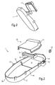
- the cover 1 designed as a heating unit comprises a housing 2, a heat protection body 3 and a plurality of heating elements 4.
- the embodiment of the cover according to the invention shown by way of example in FIGS. 1 to 3 contains four heating elements 4 arranged side by side and one above the other.
- the heating elements 4 are arranged laterally by two Support plates 5 held together as a one-piece module unit.
- the heating elements 4 are positioned relative to each other so that a passing gas stream can be optimally heated.
- the heating elements 4 are arranged inside the heat protection body 3, which thermally insulates the heating elements from the environment and at the same time forms a flow channel in order to pass a gas stream, preferably an air stream, as well as possible past the heating elements 4.
- the heat protection body 3 has an inlet opening 6 and an outlet opening 7.
- the air flow to be heated flows into the heat shield 3 at the inlet opening and is guided by the shape of the heat shield 3 through the heating elements 4, thereby heating the air flow.
- the heated air flow flows out of the heat shield 3 at the outlet opening 7.
- the heat protection body 3 is made of a corrosion-resistant metal sheet, for example a CrNi steel sheet.
- the heat-shielding effect of the heat protection body 3 is particularly important because 4 temperatures up to 600 ° C may occur in the interior of the heat shield in the heating elements. In this case, the surface temperature on the outside must not exceed a permissible value, for example according to a VDE directive 85 ° C. To make matters worse in the heat insulation that the available space is extremely limited.
- the heat protection body can be embodied with a reflective surface.
- the heat protection body 9 also has a low thermal conductivity, so that the extremely high temperature from the area of the heating elements 4 can not be transmitted to the outer surface of the cover 1. Thus, the outer surface of the cover 1 can be touched by an operator without the risk of combustion.
- the heat protection body 3 is designed, for example, in two parts. It consists of a lower part 9 and an upper part 10.
- the lower part 9 is in the exemplary embodiment in Fig. 1 to 3 a punched sheet metal part to which is formed by bending the guide body 8.
- the upper part 10 of the heat shield 3 has been made in the embodiment in Fig. 1 to 3 by deep drawing.
- at least one recess 11 is formed next to the inlet opening 6 and the outlet opening 7, in which at least one temperature sensor 12 is mounted.
- the heating of the air flow can be measured within the cover 1 and the heating power of the heating elements 4 are regulated.
- a control circuit can be constructed, with which the heating elements 4 are controlled and the temperature of the air flow is controlled.
- more than two temperature sensors can be used to determine the temperature at different points of the air flow. For example, the temperature of the air flow in front of and behind the heating element 4 can be measured.
- a further temperature sensor may be arranged in the vicinity of the heating elements 4 as a protective thermostat to detect an excessive increase in temperature of the heating elements 4 and thus to prevent overheating.
- the heat shield 3 with the heating elements 4 is attached to the housing 2.
- the housing 2 is provided with fastening means 13 for releasably attaching the cover 1 to a tumble dryer.
- the fastening means 13 will be described in more detail below.
- the cover 1 further comprises a sealing lip 14, through which the cover 1 is substantially gas-tight attachable to the tumble dryer. This prevents that part of the heated air flow is discharged to the outside.
- the housing 2 of the embodiment shown in Figs. 1 to 3 is made of a heat-insulating plastic. This is advantageous so that the high temperature in the region of the heating elements 4 is not transmitted to the outer surface of the cover 1 for the reasons mentioned above.
- the housing 2 is made of an electrically insulating plastic in order to electrically insulate the heating elements 4 from the remaining parts of the tumble dryer and also to the outside.
- the execution of the housing 2 made of an electrically insulating material counteracts a spreading of leakage currents.
- a temperature-resistant material z. B. a sheet metal part are attached to the housing 2, so that in this protection area, the housing 2 is protected.
- the housing 2 is designed container-shaped and has a circumferential container wall 2a, which encloses an inner space 2b.
- the cover 1 according to the invention in which the heat protection body 3 with the heating elements 4 are mounted in the interior 2b of the housing 2 and do not protrude beyond the container wall 2a, to a wall 17 'of a clothes dryer 17 attachable.
- the wall 17 ' may be flat.
- the housing 2 of the embodiment of the cover 1 according to the invention shown in FIGS. 1 to 3 is designed as an injection-molded part.
- the production of the housing by injection molding has the advantage that a large number can be produced inexpensively with high dimensional accuracy.
- the cover 1 further comprises at least one contact element 15, through which the cover 1 with its heating elements 4 and temperature sensors 12 is electrically connected.
- the contact element 15 shown in FIGS. 1 to 3 is designed, for example, as a standardized plug and integrated in the housing 2.
- a corresponding mating connector is located on the tumble dryer, so that in the mounting position of the cover 1, a plug connection produces by itself.
- Both the heating elements 4 and the temperature sensors 12 are electrically connected via the contact element 15. This has the advantage that only one contact element for electrical connection of all parts of the cover 1 is necessary.
- the housing 2 has further attachment means 16 to which the heat shield 3 is detachably attached.
- the lower part 9 of the heat protection body 3 can be locked in the running as a locking means further fastening means 16.
- the preassembled module unit of heating elements 4 and support plates 5 is placed on the lower part 9.
- the upper part 10 of the heat protection body 3 is placed and also engaged on the other fastening means 16.
- the heat protection body 3 may contain fastening means for fixing the heating elements 4 within the heat protection body 3.
- the further fastening means 16 are designed simultaneously in the form of ribs for enhancing the stability of the housing 2.
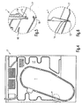
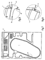
- FIG. 4 shows the rear wall of a tumble dryer 17 with the attached cover 1 according to the invention from FIGS. 1 to 3.
- FIG. 5 and FIG. 8 the detail A from FIG. 4 is shown in perspective.
- the cover 1 is not yet mounted and spaced from the clothes dryer 17.
- In the tumble dryer 17 is at least one Hole 18 for receiving the fastener 13 of the cover 1 executed.
- Fig. 6 and Fig. 9 show the detail A of Fig. 4 with mounted cover 1.
- the wedge-like designed as a clip or detent fastening means 13 is locked in Fig. 5 in the hole 18 which is designed as a counter-detent.
- the sealing lip 14 is compressed in the assembled state and seals the cover 1 substantially airtight or gas-tight.
- the compressed sealing lip 14 generates a clamping force which pushes the cover 1 away from the tumble dryer 17, thereby preventing a folding of the fastening means 13 in the hole 18 during operation of the tumble dryer.
- the cover 1 is thereby mounted vibration-proof on the washer 17.
- FIG. 7 shows a further embodiment of the cover 1 according to the invention mounted on a tumble dryer 17.
- FIG. 8 shows a detail B from FIG. 7, wherein the cover 1 is shown with the tumble dryer 17 prior to assembly.
- the embodiment of the cover 1 of Fig. 7 to 9 differs by differently configured fastening means 13 and a correspondingly different hole 18.
- the fastening means 13 shown in Fig. 8 is designed dowel-shaped ,
- the hole 18 is circular and configured as a counter-catch for the fastening means 13.
- Fig. 9 shows the embodiment of the cover 1 according to the invention from FIGS. 7 and 8 in the assembled state. Similar to the embodiment in FIGS. 4 to 6, the sealing lip 14 is compressed in the assembled state with the properties already described above.
- the cover 1 is attached from the outside to a wall 17 '.
- an air supply e.g. with a fan, for generating a gas stream, with which the wet laundry is dried.
- the walls 17 ' are attached to a base frame, for example.
- the cover 1 forms with the wall 17 'in the operation of the clothes dryer 17 from the gas flow through the flow channel, through which the gas stream in the direction of the laundry to be dried can be conducted.
- the cover 1 may alternatively be designed with a flange surface instead of the sealing lip 14. This flange can both the attachment of the cover. 1 serve on a tumble dryer as well as a sealing surface opposite the tumble dryer.
- a sealant is applied to the flange surface during assembly of the cover 1 on the dryer a flange on the surface.
- the cover 1 can be attached to the tumble dryer by the sealant and simultaneously sealed.
- the sealing of the cover according to the invention with respect to the tumble dryer can alternatively be designed as a labyrinth seal.
Claims (24)
- Couverture (1) pour un sèche-linge (17), au moyen duquel, en service, un courant gazeux peut être chauffé pour sécher du linge humide, dans lequel le Couverture (1) est réalisé en tant qu'au moins une partie d'une paroi externe, en particulier d'une paroi arrière, et peut être fixé sur le sèche-linge (17) et un canal pouvant être traversé par le courant gazeux est formé par le Couverture (1) au moins par sections, caractérisé en ce que le Couverture (1) est réalisé en tant qu'unité de chauffage, dans laquelle est intégrée au moins un élément chauffant (4) autour duquel le courant gazeux peut circuler lorsque le sèche-linge (17) est en service.
- Couverture (1) selon la revendication 1, caractérisé en ce que le Couverture (1) comprend des moyens de fixation (13) permettant de fixer le Couverture (1) par l'extérieur sur le sèche-linge (17).
- Couverture (1) selon la revendication 2, caractérisé en ce que les moyens de fixation (13) sont réalisés sous forme d'éléments d'encliquetage permettant d'encliqueter le Couverture (1) sur le sèche-linge (17).
- Couverture (1) selon la revendication 2 ou 3, caractérisé en ce que les moyens de fixation (13) sont réalisés de manière à pouvoir être retirés plusieurs fois.
- Couverture (1) selon l'une quelconque des revendications précédentes, caractérisé en ce que le Couverture (1) comprend une lèvre d'étanchéité (14) permettant de fixer le Couverture (1) sur le sèche-linge (17) de manière essentiellement étanche au gaz.
- Couverture (1) selon l'une quelconque des revendications précédentes, caractérisé en ce que le Couverture (1) comprend un joint à labyrinthe permettant de fixer le Couverture (1) sur le sèche-linge (17) de manière essentiellement étanche au gaz.
- Couverture (1) selon l'une quelconque des revendications précédentes, caractérisé en ce que le Couverture (1) est fait d'un matériau calorifuge.
- Couverture (1) selon l'une quelconque des revendications précédentes, caractérisé en ce que le Couverture (1) est fait d'un matériau résistant aux températures élevées.
- Couverture (1) selon l'une quelconque des revendications précédentes, caractérisé en ce que le Couverture (1) est fait d'un matériau électriquement isolant.
- Couverture (1) selon l'une quelconque des revendications précédentes, caractérisé en ce que le Couverture (1) réalisé en tant qu'unité de chauffage comprend au moins un capteur de température (12) permettant de mesurer la température du courant gazeux.
- Couverture (1) selon l'une quelconque des revendications précédentes, caractérisé en ce que l'unité de chauffage comprend un corps calorifuge (3) qui entoure au moins partiellement l'au moins un élément chauffant (4).
- Couverture (1) selon la revendication 11, caractérisé en ce que le corps calorifuge (3) forme un canal d'écoulement pouvant être traversé par le courant gazeux.
- Couverture (1) selon la revendication 11 ou 12, caractérisé en ce que le corps calorifuge (3) est fait d'un matériau résistant aux températures élevées.
- Couverture (1) selon l'une quelconque des revendications précédentes, caractérisé en ce qu'au moins un élément de contact (15), permettant de relier électriquement l'unité de chauffage à un connecteur correspondant côté machine, est intégré.
- Couverture (1) selon la revendication 14, caractérisé en ce que l'élément de contact (15) est réalisé en tant que partie d'un connecteur enfichable.
- Couverture (1) selon la revendication 14 ou 15, caractérisé en ce que l'élément de contact (15) est intégré dans le Couverture (1).
- Couverture (1) selon l'une quelconque des revendications précédentes, caractérisé en ce que le Couverture (1) comprend un boîtier en forme de bac (2) qui est réalisé sous forme de pièce moulée par injection.
- Couverture (1) selon la revendication 17, caractérisé en ce que le boîtier (2) est réalisé sous forme de pièce de matière plastique qui est pourvue par sections d'au moins une zone de protection faite d'un autre matériau.
- Couverture (1) selon la revendication 18, caractérisé en ce que l'au moins une zone de protection est située dans une zone qui, en service, est soumise à une température élevée.
- Sèche-linge (17) pour sécher du linge humide avec un courant gazeux, dans lequel le sèche-linge (17) est réalisé avec des parois (17'), une arrivée d'air et un canal pouvant être traversé par le courant gazeux, caractérisé en ce que le sèche-linge (17) comprend un Couverture (1) selon l'une quelconque des revendications 1 à 17 et en ce que le canal est formé au moins par sections par le Couverture (1).
- Procédé de montage d'un sèche-linge (17) au moyen duquel, en service, un courant gazeux peut être chauffé pour sécher du linge humide, comprenant les étapes de procédé consistant à :- monter au préalable une unité de chauffage en fixant sur un Couverture au moins un élément chauffant (4), autour duquel le courant gazeux peut circuler lorsque le sèche-linge est en service, et former un canal pouvant être traversé ;- fixer le Couverture (1) sur le sèche-linge (17) en tant qu'au moins une partie de la paroi externe (17') du sèche-linge et relier le canal à une arrivée d'air du sèche-linge (17).
- Procédé selon la revendication 21, comprenant l'étape de procédé suivante :- fixer le Couverture sur la paroi au moyen d'un encliquetage amovible ou inamovible.
- Procédé selon la revendication 21 ou 22, comprenant l'étape de procédé suivante :- fermer simultanément le circuit d'un contact pour l'alimentation en courant de l'élément chauffant lors de la fixation du Couverture (1) sur la paroi (17').
- Procédé selon l'une quelconque des revendications 21 à 23, comprenant l'étape de procédé suivante :- rendre simultanément le canal essentiellement étanche au gaz pendant la fixation du Couverture (1) sur la paroi (17') du sèche-linge (17).
Priority Applications (6)
| Application Number | Priority Date | Filing Date | Title |
|---|---|---|---|
| EP03027650A EP1538255B1 (fr) | 2003-12-02 | 2003-12-02 | Couvercle pour un sèche-linge et procédé de son assemblage |
| DE50302587T DE50302587D1 (de) | 2003-12-02 | 2003-12-02 | Abdeckung für einen Wäschetrockner und Verfahren zu dessen Zusammenbau |
| AT03027650T ATE319874T1 (de) | 2003-12-02 | 2003-12-02 | Abdeckung für einen wäschetrockner und verfahren zu dessen zusammenbau |
| US10/999,813 US8371040B2 (en) | 2003-12-02 | 2004-11-29 | Cover for a clothes dryer and assembling method thereof |
| JP2004346859A JP2005169106A (ja) | 2003-12-02 | 2004-11-30 | 衣類乾燥器用カバー及びその組立て方法 |
| KR1020040100094A KR100676007B1 (ko) | 2003-12-02 | 2004-12-01 | 의류 건조기용 커버와 그에 대한 조립 방법 |
Applications Claiming Priority (1)
| Application Number | Priority Date | Filing Date | Title |
|---|---|---|---|
| EP03027650A EP1538255B1 (fr) | 2003-12-02 | 2003-12-02 | Couvercle pour un sèche-linge et procédé de son assemblage |
Publications (2)
| Publication Number | Publication Date |
|---|---|
| EP1538255A1 EP1538255A1 (fr) | 2005-06-08 |
| EP1538255B1 true EP1538255B1 (fr) | 2006-03-08 |
Family
ID=34442935
Family Applications (1)
| Application Number | Title | Priority Date | Filing Date |
|---|---|---|---|
| EP03027650A Revoked EP1538255B1 (fr) | 2003-12-02 | 2003-12-02 | Couvercle pour un sèche-linge et procédé de son assemblage |
Country Status (6)
| Country | Link |
|---|---|
| US (1) | US8371040B2 (fr) |
| EP (1) | EP1538255B1 (fr) |
| JP (1) | JP2005169106A (fr) |
| KR (1) | KR100676007B1 (fr) |
| AT (1) | ATE319874T1 (fr) |
| DE (1) | DE50302587D1 (fr) |
Cited By (3)
| Publication number | Priority date | Publication date | Assignee | Title |
|---|---|---|---|---|
| WO2017081225A1 (fr) | 2015-11-13 | 2017-05-18 | Dbk David + Baader Gmbh | Unité de chauffage et sèche-linge |
| EP3190228A1 (fr) | 2016-01-05 | 2017-07-12 | DBK David + Baader GmbH | Dispositif de chauffage pour sèche-linge et sèche-linge |
| EP3351678A1 (fr) | 2017-01-24 | 2018-07-25 | Whirlpool Corporation | Machine permettant de sécher le linge comprenant une unité de pompe à chaleur et son procédé de fonctionnement |
Families Citing this family (15)
| Publication number | Priority date | Publication date | Assignee | Title |
|---|---|---|---|---|
| US8799464B2 (en) | 2001-12-28 | 2014-08-05 | Motorola Mobility Llc | Multi-modal communication using a session specific proxy server |
| ATE319874T1 (de) * | 2003-12-02 | 2006-03-15 | Dbk David & Baader Gmbh | Abdeckung für einen wäschetrockner und verfahren zu dessen zusammenbau |
| US7322125B2 (en) | 2004-04-12 | 2008-01-29 | Lg Electronics Inc. | Dry heater fixing unit of drum-type washing machine combined with drier |
| DE502004010348D1 (de) * | 2004-05-07 | 2009-12-24 | Dbk David & Baader Gmbh | Heizbaugruppe für einen Wäschetrockner |
| DE102005023442A1 (de) * | 2005-05-20 | 2006-11-30 | BSH Bosch und Siemens Hausgeräte GmbH | Haushaltgerät zur Pflege von Wäschestücken insbesondere Wäschetrockner |
| US8015726B2 (en) * | 2005-06-23 | 2011-09-13 | Whirlpool Corporation | Automatic clothes dryer |
| KR101196984B1 (ko) * | 2005-08-19 | 2012-11-05 | 엘지전자 주식회사 | 건조 겸용 드럼 세탁기 및 이에 장착되는 건조 덕트어셈블리 |
| US8191388B2 (en) | 2005-08-19 | 2012-06-05 | Lg Electronics Inc. | Drying duct assembly and washing machine having the same |
| DE102005056942A1 (de) * | 2005-11-29 | 2007-05-31 | BSH Bosch und Siemens Hausgeräte GmbH | Wärmetrockner mit Peltier-Wärmepumpe |
| JP2010052851A (ja) * | 2008-08-26 | 2010-03-11 | Kyocera Mita Corp | 温風発生装置、給紙装置及びこれらを備えた画像形成装置 |
| EP2423375B1 (fr) * | 2010-08-24 | 2015-12-02 | Electrolux Home Products Corporation N.V. | Sèche-linge à tambour rotatif |
| DE102013102515B4 (de) * | 2013-03-13 | 2016-03-10 | Miele & Cie. Kg | Gehäuse für Haushaltsgeräte wie beispielsweise einen Wäschetrockner |
| DE102013102518B4 (de) * | 2013-03-13 | 2016-03-10 | Miele & Cie. Kg | Gehäuse für Haushaltsgeräte wie beispielsweise einen Wäschetrockner |
| US9771677B1 (en) * | 2016-03-09 | 2017-09-26 | Haier Us Appliance Solutions, Inc. | Dryer appliances with improved heaters |
| DE102019204424A1 (de) * | 2019-03-29 | 2020-10-01 | Polytec Plastics Germany Gmbh & Co. Kg | Wäschetrockner-Heizvorrichtung |
Family Cites Families (75)
| Publication number | Priority date | Publication date | Assignee | Title |
|---|---|---|---|---|
| US2018505A (en) * | 1931-10-09 | 1935-10-22 | Acme Sheet Metal Works | Drier |
| US2314762A (en) * | 1940-09-24 | 1943-03-23 | Fred S Boltz | Folding clothes drier and method of making same |
| CH240775A (de) | 1944-05-01 | 1946-01-31 | Rotz Albert Von | Wäsche-Trockenmaschine. |
| US2589284A (en) * | 1946-09-20 | 1952-03-18 | Hamilton Mfg Co | Drier |
| US2619734A (en) * | 1949-05-04 | 1952-12-02 | Whirlpool Co | Electrically heated drier |
| US2775047A (en) * | 1952-01-23 | 1956-12-25 | Whirlpool Seeger Corp | Drier control |
| US2742708A (en) * | 1952-07-12 | 1956-04-24 | Gen Motors Corp | Domestic appliance |
| US2748496A (en) * | 1952-10-24 | 1956-06-05 | Thor Corp | Clothes dryer |
| US2936527A (en) * | 1957-02-27 | 1960-05-17 | Easy Washing Machine Company L | Clothes drier |
| US2949679A (en) * | 1957-05-09 | 1960-08-23 | Whirlpool Co | Laundry machine with heat storage means |
| US3002288A (en) * | 1958-07-01 | 1961-10-03 | Mc Graw Edison Co | Laundry dryer with aerosol container |
| US3039285A (en) * | 1960-01-27 | 1962-06-19 | Lovell Mfg Co | Imperforate drum combination clothes washer and dryer |
| CH395863A (fr) * | 1963-06-13 | 1965-07-15 | Zuppiger Paul | Dispositif de déplacement de charges à vitesse variable |
| US3293769A (en) * | 1964-06-18 | 1966-12-27 | Whirlpool Co | Adjustable cool-down control for dryer cycle |
| DE1585978A1 (de) * | 1964-07-31 | 1969-11-20 | Siemens Elektrogeraete Gmbh | Nach dem Trommelprinzip arbeitender Waeschetrockner |
| US3449838A (en) * | 1966-09-09 | 1969-06-17 | Chancellor Chair Co | Combination wall mounted dryer and heater |
| US3545235A (en) * | 1969-02-11 | 1970-12-08 | Gen Motors Corp | Combination clothes washer and dryer |
| US3571941A (en) * | 1969-03-03 | 1971-03-23 | Whirlpool Co | Appliance control circuit |
| US3621202A (en) * | 1970-11-16 | 1971-11-16 | Gsw Ltd | Automatic drying cycle for clothes dryers |
| US3799387A (en) * | 1971-11-18 | 1974-03-26 | Whirlpool Co | Electric heating unit for clothes dryers |
| US3842319A (en) * | 1972-02-04 | 1974-10-15 | Tappan Co | Gas igniter |
| US3928910A (en) * | 1972-09-18 | 1975-12-30 | Tappan Co | Gas igniter |
| USRE29853E (en) * | 1972-09-18 | 1978-11-28 | The Tappan Company | Gas igniter |
| DE2263260C3 (de) * | 1972-12-23 | 1982-01-28 | Fritz Eichenauer GmbH & Co KG, 6744 Kandel | Heizkörper für gebläsebetriebene Heizgeräte, insbesondere Kleinheizkörper für Haartrockner o.dgl. |
| GB1482520A (en) | 1973-07-30 | 1977-08-10 | Ti Domestic Appliances Ltd | Tumbler dryers |
| JPS565560B2 (fr) * | 1973-12-26 | 1981-02-05 | ||
| US4019023A (en) * | 1975-06-16 | 1977-04-19 | Whirlpool Corporation | Electrically heated dryer |
| US4025754A (en) * | 1975-06-16 | 1977-05-24 | Whirlpool Corporation | Electrically heated dryer |
| US4041614A (en) * | 1976-07-12 | 1977-08-16 | Robinet Norman A | Clothes dryer |
| US4063590A (en) * | 1976-10-22 | 1977-12-20 | Mcconnell Christopher L | Preheater for clothes dryer |
| JPS53120053A (en) | 1977-03-30 | 1978-10-20 | Hitachi Ltd | Lubricator |
| US4207686A (en) * | 1977-12-19 | 1980-06-17 | Fedders Corporation | Air heater arrangement for a clothes dryer |
| JPS6043813B2 (ja) | 1978-11-22 | 1985-09-30 | 新日本製鐵株式会社 | 厚肉uo鋼管成形法 |
| JPS5912195Y2 (ja) * | 1980-02-06 | 1984-04-13 | 有限会社琉球スクリ−ン印刷 | Tシャツプリント装置 |
| JPS56130192A (en) | 1980-03-17 | 1981-10-12 | Hitachi Ltd | Drier |
| JPS56173194U (fr) | 1980-05-21 | 1981-12-21 | ||
| US4513545A (en) * | 1982-09-20 | 1985-04-30 | Hopkins Jr George D | Apparatus for and method of constructing, transporting and erecting a structure of two or more stories comprised of a plurality of prefabricated core modules and panelized room elements |
| DE3419743C2 (de) | 1984-05-26 | 1993-10-21 | Miele & Cie | Trommeltrockner für Wäsche |
| JPS61115598A (ja) * | 1984-11-09 | 1986-06-03 | 株式会社日立製作所 | 衣類乾燥機の糸屑捕集器 |
| JPS62186899A (ja) | 1986-02-12 | 1987-08-15 | 松下電器産業株式会社 | 衣類乾燥機 |
| US4653200A (en) * | 1986-03-05 | 1987-03-31 | Whirlpool Corporation | Lint screen shield assembly for a dryer |
| US4700495A (en) * | 1986-09-22 | 1987-10-20 | Whirlpool Corporation | Heater assembly and mounting arrangement for a dryer |
| US4857707A (en) * | 1988-04-11 | 1989-08-15 | Whirpool Corporation | Flexible frame heater element for dryer |
| IT218167Z2 (it) * | 1988-05-30 | 1992-04-08 | Zanussi A Spa Industrie | Dispositivo di riscaldamento per macchina combinata per il lavaggio e l'asciugatura della biancheria. |
| IT1225119B (it) * | 1988-07-25 | 1990-11-02 | Zanussi A Spa Industrie | Dispositivo riscaldante per macchine lavatrici e/o asciugatricidi biancheria |
| CA1293762C (fr) * | 1988-12-01 | 1991-12-31 | Robert Maurice St. Louis | Support de serpentin de chauffage, pour appareil a secher |
| GB9024419D0 (en) * | 1990-11-09 | 1991-01-02 | Ist Lab Ltd | Heating apparatus |
| DE4139588A1 (de) | 1990-12-15 | 1992-06-17 | Miele & Cie | Haushaltgeraet |
| US5161314A (en) * | 1991-06-17 | 1992-11-10 | American Dryer Corporation | Apparatus and method for controlling a drying cool-down cycle of a clothes dryer |
| US5134270A (en) * | 1991-10-08 | 1992-07-28 | Emerson Electric Co. | Heater assembly for use in clothes dryers |
| IT1259217B (it) * | 1992-06-30 | 1996-03-11 | Zanussi Elettrodomestici | Asciugabiancheria perfezionata |
| DE4327916A1 (de) | 1992-08-21 | 1994-02-24 | Miele & Cie | Wäschebehandlungsmaschine |
| CA2091940C (fr) * | 1993-03-18 | 2000-05-02 | Robert St. Louis | Sechoir a linge a deux elements et comportant un circuit d'interruption a element unique |
| US5560120A (en) * | 1995-04-20 | 1996-10-01 | Whirlpool Corporation | Lint handling system |
| CA2262971C (fr) * | 1998-03-18 | 2006-10-24 | Nemco, Inc. | Coude d'aeration de secheuse et methode d'assemblage |
| US6108940A (en) * | 1998-03-31 | 2000-08-29 | Camco Inc. | Heater housing for an electric clothes dryer |
| DE19842644A1 (de) | 1998-09-17 | 2000-03-23 | Bsh Bosch Siemens Hausgeraete | Verfahren zur Überwachung des Trocknungsluftstromes in einem Haushaltwäschetrockner sowie nach diesem Verfahren arbeitender Haushaltwäschetrockner |
| JP2000317200A (ja) | 1999-05-06 | 2000-11-21 | Hitachi Ltd | 衣類乾燥機 |
| CN100496170C (zh) * | 1999-11-30 | 2009-06-03 | 松下电器产业株式会社 | 红外线灯、加热装置和生产红外线灯的方法 |
| US6519871B2 (en) * | 2001-05-25 | 2003-02-18 | Maytag Corporation | Self programming clothes dryer system |
| US7220365B2 (en) * | 2001-08-13 | 2007-05-22 | New Qu Energy Ltd. | Devices using a medium having a high heat transfer rate |
| ITPN20020086A1 (it) | 2002-11-07 | 2004-05-08 | Irca Spa | Condotto con resistenza elettrica perfezionata e |
| KR100913083B1 (ko) * | 2002-11-22 | 2009-08-19 | 엘지전자 주식회사 | 빨래건조기의 프론트 캐비닛과 프론트 서포트간의 조립구조 |
| US7005618B2 (en) * | 2003-06-27 | 2006-02-28 | General Electric Company | Clothes dryer apparatus and method |
| ATE319874T1 (de) * | 2003-12-02 | 2006-03-15 | Dbk David & Baader Gmbh | Abdeckung für einen wäschetrockner und verfahren zu dessen zusammenbau |
| DE502004010348D1 (de) * | 2004-05-07 | 2009-12-24 | Dbk David & Baader Gmbh | Heizbaugruppe für einen Wäschetrockner |
| US20060034593A1 (en) * | 2004-08-12 | 2006-02-16 | American Dryer Corp. | Heating element compartment for electric dryer applications |
| DE102006002713A1 (de) * | 2005-03-18 | 2006-10-12 | BSH Bosch und Siemens Hausgeräte GmbH | Frontbaugruppe für eine Wäschetrockenmaschine |
| US20070006479A1 (en) * | 2005-07-11 | 2007-01-11 | Salgado-Mangual Rafael A | Water-based heater for an electric clothes dryer |
| US20070062513A1 (en) * | 2005-09-21 | 2007-03-22 | Gagas John M | Cooking system with ventilator and blower |
| US7161120B1 (en) * | 2006-03-16 | 2007-01-09 | Michael Maurice Stroud | Garment warming system |
| US20070261997A1 (en) * | 2006-05-11 | 2007-11-15 | Hmc Solutions, Llc, D/B/A Hmc Solutions | Automated dry cleaning assembly conveyor system |
| US20080124667A1 (en) * | 2006-10-18 | 2008-05-29 | Honeywell International Inc. | Gas pressure control for warm air furnaces |
| US8635997B2 (en) * | 2006-10-18 | 2014-01-28 | Honeywell International Inc. | Systems and methods for controlling gas pressure to gas-fired appliances |
| US20090010801A1 (en) * | 2007-05-15 | 2009-01-08 | Murphy Oliver J | Air cleaner |
-
2003
- 2003-12-02 AT AT03027650T patent/ATE319874T1/de not_active IP Right Cessation
- 2003-12-02 DE DE50302587T patent/DE50302587D1/de not_active Expired - Lifetime
- 2003-12-02 EP EP03027650A patent/EP1538255B1/fr not_active Revoked
-
2004
- 2004-11-29 US US10/999,813 patent/US8371040B2/en not_active Expired - Fee Related
- 2004-11-30 JP JP2004346859A patent/JP2005169106A/ja active Pending
- 2004-12-01 KR KR1020040100094A patent/KR100676007B1/ko not_active IP Right Cessation
Cited By (5)
| Publication number | Priority date | Publication date | Assignee | Title |
|---|---|---|---|---|
| WO2017081225A1 (fr) | 2015-11-13 | 2017-05-18 | Dbk David + Baader Gmbh | Unité de chauffage et sèche-linge |
| DE102016110023A1 (de) | 2015-11-13 | 2017-05-18 | Dbk David + Baader Gmbh | Heizeinheit und Wäschetrockner |
| EP3190228A1 (fr) | 2016-01-05 | 2017-07-12 | DBK David + Baader GmbH | Dispositif de chauffage pour sèche-linge et sèche-linge |
| US10280555B2 (en) | 2016-01-05 | 2019-05-07 | Dbk David + Baader Gmbh | Heating device for tumble dryer and tumble dryer |
| EP3351678A1 (fr) | 2017-01-24 | 2018-07-25 | Whirlpool Corporation | Machine permettant de sécher le linge comprenant une unité de pompe à chaleur et son procédé de fonctionnement |
Also Published As
| Publication number | Publication date |
|---|---|
| KR20050053341A (ko) | 2005-06-08 |
| JP2005169106A (ja) | 2005-06-30 |
| ATE319874T1 (de) | 2006-03-15 |
| EP1538255A1 (fr) | 2005-06-08 |
| DE50302587D1 (de) | 2006-05-04 |
| US8371040B2 (en) | 2013-02-12 |
| US20050217138A1 (en) | 2005-10-06 |
| KR100676007B1 (ko) | 2007-01-29 |
Similar Documents
| Publication | Publication Date | Title |
|---|---|---|
| EP1538255B1 (fr) | Couvercle pour un sèche-linge et procédé de son assemblage | |
| DE102014117687B4 (de) | Vorrichtung zum Einspritzen eines Reduktionsmittels und entsprechender Abgasstrang | |
| DE3446950C1 (de) | Steuervorrichtung fuer die Kuehlluft luft-fluessigkeits-gekuehlter Brennkraftmaschinen,insbesondere von Kraftfahrzeugen | |
| DE102008021853B4 (de) | Bekleidungsbehandlungsmaschine | |
| EP2608632B1 (fr) | Dispositif de chauffage électrique et cadre associé | |
| EP2884199B1 (fr) | Dispositif de chauffage électrique | |
| EP2884817B1 (fr) | Dispositif de chauffage électrique et son procédé de fabrication | |
| EP2607121A1 (fr) | Dispositif de chauffage électrique, en particulier pour un véhicule automobile | |
| EP2608633A1 (fr) | Elément générateur de chaleur | |
| DE2907619A1 (de) | Leicht-dampfbuegeleisen | |
| EP2884198B1 (fr) | Dispositif de chauffage électrique | |
| EP1885936B1 (fr) | Appareil menager pour entretenir du linge, notamment seche-linge | |
| EP1557601B1 (fr) | Clip de chauffage pour une conduite de fluide | |
| EP2986769B1 (fr) | Dispositif de chauffage de surface pour le chauffage de l'eau dans un récipient à lessive, lave-linge et procédé de fabrication d'un dispositif de chauffage de surface | |
| DE10059167A1 (de) | Backofen | |
| DE102016110023A1 (de) | Heizeinheit und Wäschetrockner | |
| EP1593772B1 (fr) | Sous-ensemble chauffant d'un sèche-linge | |
| DE19949587C2 (de) | Schutzeinheit für elektrische Vorrichtungen | |
| WO2019120980A1 (fr) | Échangeur thermique à contre-courant | |
| EP2125404B1 (fr) | Dispositif de chauffage d'un courant d'air par un voile chauffant | |
| DE102010029491B4 (de) | Baugruppe und Haushaltswäschetrockner mit dieser Baugruppe | |
| DE19925444C2 (de) | Kombination Wärmetauscher mit PTC-Heizregister | |
| DE102010021165A1 (de) | Heizanordnung | |
| DE10235601A1 (de) | Wärmetauscheranordnung für ein Heizgerät, insbesondere Standheizung oder Zusatzheizer für ein Fahrzeug | |
| EP2884197A1 (fr) | Dispositif de chauffage électrique et son procédé de fabrication |
Legal Events
| Date | Code | Title | Description |
|---|---|---|---|
| PUAI | Public reference made under article 153(3) epc to a published international application that has entered the european phase |
Free format text: ORIGINAL CODE: 0009012 |
|
| 17P | Request for examination filed |
Effective date: 20040823 |
|
| AK | Designated contracting states |
Kind code of ref document: A1 Designated state(s): AT BE BG CH CY CZ DE DK EE ES FI FR GB GR HU IE IT LI LU MC NL PT RO SE SI SK TR |
|
| AX | Request for extension of the european patent |
Extension state: AL LT LV MK |
|
| GRAP | Despatch of communication of intention to grant a patent |
Free format text: ORIGINAL CODE: EPIDOSNIGR1 |
|
| GRAS | Grant fee paid |
Free format text: ORIGINAL CODE: EPIDOSNIGR3 |
|
| GRAA | (expected) grant |
Free format text: ORIGINAL CODE: 0009210 |
|
| AKX | Designation fees paid |
Designated state(s): AT BE BG CH CY CZ DE DK EE ES FI FR GB GR HU IE IT LI LU MC NL PT RO SE SI SK TR |
|
| AK | Designated contracting states |
Kind code of ref document: B1 Designated state(s): AT BE BG CH CY CZ DE DK EE ES FI FR GB GR HU IE IT LI LU MC NL PT RO SE SI SK TR |
|
| PG25 | Lapsed in a contracting state [announced via postgrant information from national office to epo] |
Ref country code: FI Free format text: LAPSE BECAUSE OF FAILURE TO SUBMIT A TRANSLATION OF THE DESCRIPTION OR TO PAY THE FEE WITHIN THE PRESCRIBED TIME-LIMIT Effective date: 20060308 Ref country code: IE Free format text: LAPSE BECAUSE OF FAILURE TO SUBMIT A TRANSLATION OF THE DESCRIPTION OR TO PAY THE FEE WITHIN THE PRESCRIBED TIME-LIMIT Effective date: 20060308 Ref country code: SK Free format text: LAPSE BECAUSE OF FAILURE TO SUBMIT A TRANSLATION OF THE DESCRIPTION OR TO PAY THE FEE WITHIN THE PRESCRIBED TIME-LIMIT Effective date: 20060308 Ref country code: NL Free format text: LAPSE BECAUSE OF FAILURE TO SUBMIT A TRANSLATION OF THE DESCRIPTION OR TO PAY THE FEE WITHIN THE PRESCRIBED TIME-LIMIT Effective date: 20060308 Ref country code: SI Free format text: LAPSE BECAUSE OF FAILURE TO SUBMIT A TRANSLATION OF THE DESCRIPTION OR TO PAY THE FEE WITHIN THE PRESCRIBED TIME-LIMIT Effective date: 20060308 Ref country code: RO Free format text: LAPSE BECAUSE OF FAILURE TO SUBMIT A TRANSLATION OF THE DESCRIPTION OR TO PAY THE FEE WITHIN THE PRESCRIBED TIME-LIMIT Effective date: 20060308 |
|
| REG | Reference to a national code |
Ref country code: GB Ref legal event code: FG4D Free format text: NOT ENGLISH |
|
| REG | Reference to a national code |
Ref country code: CH Ref legal event code: EP |
|
| REG | Reference to a national code |
Ref country code: IE Ref legal event code: FG4D Free format text: LANGUAGE OF EP DOCUMENT: GERMAN |
|
| REF | Corresponds to: |
Ref document number: 50302587 Country of ref document: DE Date of ref document: 20060504 Kind code of ref document: P |
|
| PG25 | Lapsed in a contracting state [announced via postgrant information from national office to epo] |
Ref country code: SE Free format text: LAPSE BECAUSE OF FAILURE TO SUBMIT A TRANSLATION OF THE DESCRIPTION OR TO PAY THE FEE WITHIN THE PRESCRIBED TIME-LIMIT Effective date: 20060608 Ref country code: DK Free format text: LAPSE BECAUSE OF FAILURE TO SUBMIT A TRANSLATION OF THE DESCRIPTION OR TO PAY THE FEE WITHIN THE PRESCRIBED TIME-LIMIT Effective date: 20060608 Ref country code: BG Free format text: LAPSE BECAUSE OF FAILURE TO SUBMIT A TRANSLATION OF THE DESCRIPTION OR TO PAY THE FEE WITHIN THE PRESCRIBED TIME-LIMIT Effective date: 20060608 |
|
| PG25 | Lapsed in a contracting state [announced via postgrant information from national office to epo] |
Ref country code: ES Free format text: LAPSE BECAUSE OF FAILURE TO SUBMIT A TRANSLATION OF THE DESCRIPTION OR TO PAY THE FEE WITHIN THE PRESCRIBED TIME-LIMIT Effective date: 20060619 |
|
| GBT | Gb: translation of ep patent filed (gb section 77(6)(a)/1977) |
Effective date: 20060531 |
|
| PG25 | Lapsed in a contracting state [announced via postgrant information from national office to epo] |
Ref country code: PT Free format text: LAPSE BECAUSE OF FAILURE TO SUBMIT A TRANSLATION OF THE DESCRIPTION OR TO PAY THE FEE WITHIN THE PRESCRIBED TIME-LIMIT Effective date: 20060808 |
|
| NLV1 | Nl: lapsed or annulled due to failure to fulfill the requirements of art. 29p and 29m of the patents act | ||
| ET | Fr: translation filed | ||
| REG | Reference to a national code |
Ref country code: IE Ref legal event code: FD4D |
|
| PLBI | Opposition filed |
Free format text: ORIGINAL CODE: 0009260 |
|
| PG25 | Lapsed in a contracting state [announced via postgrant information from national office to epo] |
Ref country code: MC Free format text: LAPSE BECAUSE OF NON-PAYMENT OF DUE FEES Effective date: 20061231 Ref country code: BE Free format text: LAPSE BECAUSE OF NON-PAYMENT OF DUE FEES Effective date: 20061231 |
|
| PLAX | Notice of opposition and request to file observation + time limit sent |
Free format text: ORIGINAL CODE: EPIDOSNOBS2 |
|
| 26 | Opposition filed |
Opponent name: BSH BOSCH UND SIEMENS HAUSGERAETE GMBH Effective date: 20061208 Opponent name: INDESIT COMPANY UK LIMITED Effective date: 20061208 |
|
| PLAF | Information modified related to communication of a notice of opposition and request to file observations + time limit |
Free format text: ORIGINAL CODE: EPIDOSCOBS2 |
|
| PLBB | Reply of patent proprietor to notice(s) of opposition received |
Free format text: ORIGINAL CODE: EPIDOSNOBS3 |
|
| BERE | Be: lapsed |
Owner name: DBK DAVID + BAADER G.M.B.H. Effective date: 20061231 |
|
| PG25 | Lapsed in a contracting state [announced via postgrant information from national office to epo] |
Ref country code: AT Free format text: LAPSE BECAUSE OF NON-PAYMENT OF DUE FEES Effective date: 20061202 |
|
| PG25 | Lapsed in a contracting state [announced via postgrant information from national office to epo] |
Ref country code: GR Free format text: LAPSE BECAUSE OF FAILURE TO SUBMIT A TRANSLATION OF THE DESCRIPTION OR TO PAY THE FEE WITHIN THE PRESCRIBED TIME-LIMIT Effective date: 20060609 Ref country code: CZ Free format text: LAPSE BECAUSE OF FAILURE TO SUBMIT A TRANSLATION OF THE DESCRIPTION OR TO PAY THE FEE WITHIN THE PRESCRIBED TIME-LIMIT Effective date: 20060308 |
|
| PG25 | Lapsed in a contracting state [announced via postgrant information from national office to epo] |
Ref country code: EE Free format text: LAPSE BECAUSE OF FAILURE TO SUBMIT A TRANSLATION OF THE DESCRIPTION OR TO PAY THE FEE WITHIN THE PRESCRIBED TIME-LIMIT Effective date: 20060308 |
|
| PG25 | Lapsed in a contracting state [announced via postgrant information from national office to epo] |
Ref country code: LU Free format text: LAPSE BECAUSE OF NON-PAYMENT OF DUE FEES Effective date: 20061202 Ref country code: HU Free format text: LAPSE BECAUSE OF FAILURE TO SUBMIT A TRANSLATION OF THE DESCRIPTION OR TO PAY THE FEE WITHIN THE PRESCRIBED TIME-LIMIT Effective date: 20060909 |
|
| REG | Reference to a national code |
Ref country code: CH Ref legal event code: PL |
|
| PG25 | Lapsed in a contracting state [announced via postgrant information from national office to epo] |
Ref country code: LI Free format text: LAPSE BECAUSE OF NON-PAYMENT OF DUE FEES Effective date: 20071231 Ref country code: CH Free format text: LAPSE BECAUSE OF NON-PAYMENT OF DUE FEES Effective date: 20071231 |
|
| PG25 | Lapsed in a contracting state [announced via postgrant information from national office to epo] |
Ref country code: CY Free format text: LAPSE BECAUSE OF FAILURE TO SUBMIT A TRANSLATION OF THE DESCRIPTION OR TO PAY THE FEE WITHIN THE PRESCRIBED TIME-LIMIT Effective date: 20060308 |
|
| PLCK | Communication despatched that opposition was rejected |
Free format text: ORIGINAL CODE: EPIDOSNREJ1 |
|
| APBM | Appeal reference recorded |
Free format text: ORIGINAL CODE: EPIDOSNREFNO |
|
| APBP | Date of receipt of notice of appeal recorded |
Free format text: ORIGINAL CODE: EPIDOSNNOA2O |
|
| APAH | Appeal reference modified |
Free format text: ORIGINAL CODE: EPIDOSCREFNO |
|
| APBQ | Date of receipt of statement of grounds of appeal recorded |
Free format text: ORIGINAL CODE: EPIDOSNNOA3O |
|
| RAP2 | Party data changed (patent owner data changed or rights of a patent transferred) |
Owner name: DBK DAVID + BAADER GMBH |
|
| REG | Reference to a national code |
Ref country code: DE Ref legal event code: R082 Ref document number: 50302587 Country of ref document: DE Representative=s name: WINTER, BRANDL, FUERNISS, HUEBNER, ROESS, KAIS, DE |
|
| REG | Reference to a national code |
Ref country code: DE Ref legal event code: R081 Ref document number: 50302587 Country of ref document: DE Owner name: DBK DAVID + BAADER GMBH, DE Free format text: FORMER OWNER: DBK DAVID + BAADER GMBH, 76870 KANDEL, DE Effective date: 20130807 Ref country code: DE Ref legal event code: R082 Ref document number: 50302587 Country of ref document: DE Representative=s name: WINTER, BRANDL, FUERNISS, HUEBNER, ROESS, KAIS, DE Effective date: 20130807 |
|
| PLAB | Opposition data, opponent's data or that of the opponent's representative modified |
Free format text: ORIGINAL CODE: 0009299OPPO |
|
| R26 | Opposition filed (corrected) |
Opponent name: INDESIT COMPANY UK LIMITED Effective date: 20061208 |
|
| PGFP | Annual fee paid to national office [announced via postgrant information from national office to epo] |
Ref country code: TR Payment date: 20141121 Year of fee payment: 12 Ref country code: GB Payment date: 20141216 Year of fee payment: 12 |
|
| PGFP | Annual fee paid to national office [announced via postgrant information from national office to epo] |
Ref country code: FR Payment date: 20141212 Year of fee payment: 12 |
|
| PLAB | Opposition data, opponent's data or that of the opponent's representative modified |
Free format text: ORIGINAL CODE: 0009299OPPO |
|
| PLAB | Opposition data, opponent's data or that of the opponent's representative modified |
Free format text: ORIGINAL CODE: 0009299OPPO |
|
| PGFP | Annual fee paid to national office [announced via postgrant information from national office to epo] |
Ref country code: IT Payment date: 20141217 Year of fee payment: 12 |
|
| R26 | Opposition filed (corrected) |
Opponent name: INDESIT COMPANY UK LIMITED Effective date: 20061208 |
|
| R26 | Opposition filed (corrected) |
Opponent name: BSH HAUSGERAETE GMBH Effective date: 20061208 |
|
| PGFP | Annual fee paid to national office [announced via postgrant information from national office to epo] |
Ref country code: DE Payment date: 20141218 Year of fee payment: 12 |
|
| REG | Reference to a national code |
Ref country code: DE Ref legal event code: R064 Ref document number: 50302587 Country of ref document: DE Ref country code: DE Ref legal event code: R103 Ref document number: 50302587 Country of ref document: DE |
|
| APBU | Appeal procedure closed |
Free format text: ORIGINAL CODE: EPIDOSNNOA9O |
|
| RDAF | Communication despatched that patent is revoked |
Free format text: ORIGINAL CODE: EPIDOSNREV1 |
|
| RDAG | Patent revoked |
Free format text: ORIGINAL CODE: 0009271 |
|
| STAA | Information on the status of an ep patent application or granted ep patent |
Free format text: STATUS: PATENT REVOKED |
|
| 27W | Patent revoked |
Effective date: 20150730 |
|
| GBPR | Gb: patent revoked under art. 102 of the ep convention designating the uk as contracting state |
Effective date: 20150730 |
|
| REG | Reference to a national code |
Ref country code: AT Ref legal event code: MA03 Ref document number: 319874 Country of ref document: AT Kind code of ref document: T Effective date: 20150730 |