EP1538255B1 - Cover for a laundry dryer and process for its assembly - Google Patents
Cover for a laundry dryer and process for its assembly Download PDFInfo
- Publication number
- EP1538255B1 EP1538255B1 EP03027650A EP03027650A EP1538255B1 EP 1538255 B1 EP1538255 B1 EP 1538255B1 EP 03027650 A EP03027650 A EP 03027650A EP 03027650 A EP03027650 A EP 03027650A EP 1538255 B1 EP1538255 B1 EP 1538255B1
- Authority
- EP
- European Patent Office
- Prior art keywords
- cover
- laundry dryer
- channel
- dryer
- flow
- Prior art date
- Legal status (The legal status is an assumption and is not a legal conclusion. Google has not performed a legal analysis and makes no representation as to the accuracy of the status listed.)
- Revoked
Links
Images

Classifications
-
- D—TEXTILES; PAPER
- D06—TREATMENT OF TEXTILES OR THE LIKE; LAUNDERING; FLEXIBLE MATERIALS NOT OTHERWISE PROVIDED FOR
- D06F—LAUNDERING, DRYING, IRONING, PRESSING OR FOLDING TEXTILE ARTICLES
- D06F58/00—Domestic laundry dryers
- D06F58/20—General details of domestic laundry dryers
-
- D—TEXTILES; PAPER
- D06—TREATMENT OF TEXTILES OR THE LIKE; LAUNDERING; FLEXIBLE MATERIALS NOT OTHERWISE PROVIDED FOR
- D06F—LAUNDERING, DRYING, IRONING, PRESSING OR FOLDING TEXTILE ARTICLES
- D06F58/00—Domestic laundry dryers
- D06F58/20—General details of domestic laundry dryers
- D06F58/26—Heating arrangements, e.g. gas heating equipment
-
- D—TEXTILES; PAPER
- D06—TREATMENT OF TEXTILES OR THE LIKE; LAUNDERING; FLEXIBLE MATERIALS NOT OTHERWISE PROVIDED FOR
- D06F—LAUNDERING, DRYING, IRONING, PRESSING OR FOLDING TEXTILE ARTICLES
- D06F39/00—Details of washing machines not specific to a single type of machines covered by groups D06F9/00 - D06F27/00
- D06F39/12—Casings; Tubs
-
- D—TEXTILES; PAPER
- D06—TREATMENT OF TEXTILES OR THE LIKE; LAUNDERING; FLEXIBLE MATERIALS NOT OTHERWISE PROVIDED FOR
- D06F—LAUNDERING, DRYING, IRONING, PRESSING OR FOLDING TEXTILE ARTICLES
- D06F58/00—Domestic laundry dryers
- D06F58/10—Drying cabinets or drying chambers having heating or ventilating means
-
- D—TEXTILES; PAPER
- D06—TREATMENT OF TEXTILES OR THE LIKE; LAUNDERING; FLEXIBLE MATERIALS NOT OTHERWISE PROVIDED FOR
- D06F—LAUNDERING, DRYING, IRONING, PRESSING OR FOLDING TEXTILE ARTICLES
- D06F2103/00—Parameters monitored or detected for the control of domestic laundry washing machines, washer-dryers or laundry dryers
- D06F2103/56—Parameters monitored or detected for the control of domestic laundry washing machines, washer-dryers or laundry dryers related to air ducts, e.g. position of flow diverters
-
- D—TEXTILES; PAPER
- D06—TREATMENT OF TEXTILES OR THE LIKE; LAUNDERING; FLEXIBLE MATERIALS NOT OTHERWISE PROVIDED FOR
- D06F—LAUNDERING, DRYING, IRONING, PRESSING OR FOLDING TEXTILE ARTICLES
- D06F2105/00—Systems or parameters controlled or affected by the control systems of washing machines, washer-dryers or laundry dryers
- D06F2105/28—Electric heating
-
- D—TEXTILES; PAPER
- D06—TREATMENT OF TEXTILES OR THE LIKE; LAUNDERING; FLEXIBLE MATERIALS NOT OTHERWISE PROVIDED FOR
- D06F—LAUNDERING, DRYING, IRONING, PRESSING OR FOLDING TEXTILE ARTICLES
- D06F2105/00—Systems or parameters controlled or affected by the control systems of washing machines, washer-dryers or laundry dryers
- D06F2105/30—Blowers
Definitions
- the invention relates to a cover for a tumble dryer, through which a gaseous stream for drying damp laundry can be heated in operation, wherein the cover designed as at least a portion of an outer wall, in particular a rear wall, attachable to the tumble dryer and the cover of a flow-through by the gas flow channel at least partially formed.
- clothes dryers are made by attaching a rotatable laundry drum with a drive together with an air supply and heating elements for air supply to a base frame and then the walls are mounted on the base frame. From the air supply, the gas stream is passed to dry the laundry through a channel in which the gas stream is heated simultaneously by the heating element. This channel is located after attaching the walls inside the tumble dryer and is at least partially limited by a wall, typically the rear wall of the tumble dryer.
- Such clothes dryers with heating elements are described in EP-A-0 344 549 and EP-A-0 352 499.
- the heating elements are mounted in a arranged inside the clothes dryer washing tub umströmbar from the gas stream.
- the object of the present invention is to reduce the manufacturing cost and to improve the ease of installation of the tumble dryer.
- the cover is designed as a heating unit in which at least one heating element of the gas stream in the operation of the tumble dryer is umströmbar integrated.
- This solution is structurally simple and has the advantage that the cover can be pre-assembled as a heating unit and compared to the prior art easier installation and removal of at least one heating element allows. As a result, the assembly costs and thus also the production costs of the tumble dryer can be reduced.
- the heating element is already mitausgen already when removing the cover and is therefore easily accessible.
- the inventive solution can be dispensed with by the inventive solution to a separately installed in the dryer heating element housing, as used in dryers from the prior art.
- the housing of the heating element also forms in known dryers demolition edges, such. at the passages in the housing. Without the housing so far taken into account demolition edges are avoided, thereby improving the flow of air.
- the double function as a cover and heating element of the previously used in the interior of the tumble dryer for the heating and the channels space used so that e.g. a larger laundry drum, which is usually arranged in front of the heating unit, can be used.
- the cover of the invention can be further developed by different, mutually independent, each advantageous embodiments. These refinements and the advantages associated with the respective embodiments will be briefly discussed below.
- the cover may comprise attachment means with which the cover is preferably detachably attachable from the outside to the tumble dryer.
- attachment means with which the cover is preferably detachably attachable from the outside to the tumble dryer.
- the fastening means of the cover can be configured as detents, with which the cover on the tumble dryer is preferably releasably latched.
- the cover can be attached even faster to the dryer, thereby reducing the assembly time and thus the installation costs significantly, since covers are attached from the prior art with a variety of screw and time-consuming and costly.
- the cover may comprise a sealing lip, through which the cover essentially gas-tight attachable to the tumble dryer.
- the sealing lip may be made of a resilient plastic material in order to be able to compensate for material tolerances on both the cover and the tumble dryer.
- the cover can be sealed by a labyrinth seal. In the labyrinth seal, another seal may be surrounded by an additional sealing labyrinth arrangement.
- the cover can form a flange surface with which the cover can be attached to the tumble dryer.
- a flange has the advantage that it can be designed relatively large area and the large-area flange can be used as a sealing surface or for attaching fasteners.
- the flange surface may also be used as an adhesive surface for attaching the cover to the tumble dryer with an adhesive.
- the cover can be produced from an electrically insulating material.
- the electrically operated heating element is isolated and no current can flow to the outside.
- the risk of electric shock when touching the cover of the tumble dryer is avoided and applicable safety guidelines are met.
- This embodiment of the cover according to the invention also prevents unwanted electrical effects, such. B. the possible spread of leakage currents.
- the heating unit is taken separately in a housing in tumble dryers from the prior art and additionally covered with the rear wall, which is material and cost-intensive compared to the inventive solution.
- the cover designed as a heating unit can comprise at least one measuring sensor with which the temperature of the gas stream can be measured.
- the gas stream can be measured, for example, before or behind the heating element in order to regulate the energy supply of the heating element and thereby optimally heat the gas stream.
- a sensor can also be used as a protective thermostat of the heating element and thus prevent overheating of the heating element.
- the sensor may be arranged, for example, in the region of the channel.
- the cover In order not to direct the heat energy generated by the heating element to the outside, the cover can be made in an advantageous development of a heat-insulating material with low thermal conductivity. As a result, no heat energy is wasted and, moreover, the cover on its outside does not heat up so much that there is a risk of burning when the cover is touched. This contributes to compliance with prescribed safety guidelines with regard to the permissible outside temperature of the tumble dryer and in particular the energy consumption.
- the cover may preferably be made of a temperature-resistant material. The thermal insulation can also be improved by providing additional protection areas of heat-resistant materials at high-temperature areas.
- the heating unit may comprise a thermal protection body which at least partially surrounds the at least one heating element and secures the environment from the influence of heat.
- the heat protection body can form a flow channel through which the gas stream can flow.
- the flow channel of the gas stream is targeted and with low losses to the at least one Conducted heating element, so that an effective heating of the gas flow is ensured.
- the gas flow is passed through the flow channel after flowing through the heating unit with low flow losses in the laundry drum of the clothes dryer, whereby the generated heat energy of the laundry is supplied effectively and energy-saving.
- the heating element can be arranged in the flow channel.
- the heat shield can be made of a heat-insulating and temperature-resistant material, preferably a plastic.
- the heat shield can also be made of a metal.
- the metallic heat shield has the advantage that it can be easily and inexpensively, for example by deep drawing, can be produced.
- the heat shield of a corrosion resistant material, for. As a CrNi steel, to prevent corrosion of the heat shield, which is exposed in the tumble dryer, for example, moisture.
- the cover may include further attachment means to which the heat shield is releasably attached. This has the advantage that the heat protection body can be mounted on the cover easily and without additional fastening means and thus reduce the assembly and manufacturing costs of the heating unit.
- At least one contact element can be integrated in the cover, with which the heating unit can be electrically connected to a counterpart contact on the machine side.
- the heating unit can be simply connected to a voltage source before being attached to the tumble dryer.
- the contact element can be designed as part of a plug connection, whereby a quick and easy connection of the contact element is ensured.
- the connection of the heating unit can also be done by a single, possibly standardized plug element, which further reduces the required connection time. In this case, the different electrical lines of the at least one heating element and the at least one sensor in the one plug element connected. The plug element is inserted into a corresponding mating plug element of the tumble dryer.
- the contact element can be integrated in a further advantageous embodiment in the cover to further simplify the attachment of the cover to the tumble dryer.
- the cover may be formed as a container-shaped housing, which is designed as an injection molded part. Injection molded parts can be produced with a high degree of dimensional accuracy and, when produced in large quantities, are very cost-effective. Due to the container-shaped design of the housing, e.g. With a high border, the cover is despite the arranged individual parts of the heating unit attached to a flat wall, thereby forming the flow through the gas flow channel.
- the container-shaped housing can be configured as a plastic part, which is provided in sections with at least one protective area made of another material, preferably a metal sheet.
- the stability and temperature resistance of the housing are improved.
- the other materials can be arranged both on the plastic part as well as a layer in the plastic part.
- the at least one protection region can be arranged in a region in which a high temperature occurs during operation. This improves the thermal insulation and temperature resistance of the housing.
- the cover can be attached to the tumble dryer from the outside. This has the advantage that the cover designed in this way is particularly easy to mount on the tumble dryer.
- the invention relates not only to the cover described above and its embodiments, but also to a tumble dryer for drying damp laundry with a gas stream, wherein the tumble dryer is designed with walls, an air supply and a channel through which the gas stream can flow.
- To the assembly of the tumble dryer To facilitate the tumble dryer comprises a cover according to one of the above embodiments and the channel is at least partially formed by the cover.
- the invention relates not only to the above-described devices and their further embodiments, but also to a method for assembling a tumble dryer through which a gaseous stream for drying damp laundry can be heated during operation.
- the invention provides that a heating unit is mounted by attaching at least one during operation of the tumble dryer flowable by the gas flow heater on a cover and a flow-through channel is formed and that the cover on the dryer as at least a portion of the outer wall attached to the tumble dryer and the channel is connected to an air supply of the clothes dryer.
- the cover can be attached to the wall by releasable or non-releasable latching in order to simplify the installation of the tumble dryer. For the same reason, a contact to the power supply of the heating element when attaching the cover to the wall can be closed simultaneously. Furthermore, during the attachment of the cover to the wall of the tumble dryer, the channel can be sealed in a substantially gastight manner at the same time.
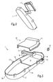
- the cover 1 designed as a heating unit comprises a housing 2, a heat protection body 3 and a plurality of heating elements 4.
- the embodiment of the cover according to the invention shown by way of example in FIGS. 1 to 3 contains four heating elements 4 arranged side by side and one above the other.
- the heating elements 4 are arranged laterally by two Support plates 5 held together as a one-piece module unit.
- the heating elements 4 are positioned relative to each other so that a passing gas stream can be optimally heated.
- the heating elements 4 are arranged inside the heat protection body 3, which thermally insulates the heating elements from the environment and at the same time forms a flow channel in order to pass a gas stream, preferably an air stream, as well as possible past the heating elements 4.
- the heat protection body 3 has an inlet opening 6 and an outlet opening 7.
- the air flow to be heated flows into the heat shield 3 at the inlet opening and is guided by the shape of the heat shield 3 through the heating elements 4, thereby heating the air flow.
- the heated air flow flows out of the heat shield 3 at the outlet opening 7.
- the heat protection body 3 is made of a corrosion-resistant metal sheet, for example a CrNi steel sheet.
- the heat-shielding effect of the heat protection body 3 is particularly important because 4 temperatures up to 600 ° C may occur in the interior of the heat shield in the heating elements. In this case, the surface temperature on the outside must not exceed a permissible value, for example according to a VDE directive 85 ° C. To make matters worse in the heat insulation that the available space is extremely limited.
- the heat protection body can be embodied with a reflective surface.
- the heat protection body 9 also has a low thermal conductivity, so that the extremely high temperature from the area of the heating elements 4 can not be transmitted to the outer surface of the cover 1. Thus, the outer surface of the cover 1 can be touched by an operator without the risk of combustion.
- the heat protection body 3 is designed, for example, in two parts. It consists of a lower part 9 and an upper part 10.
- the lower part 9 is in the exemplary embodiment in Fig. 1 to 3 a punched sheet metal part to which is formed by bending the guide body 8.
- the upper part 10 of the heat shield 3 has been made in the embodiment in Fig. 1 to 3 by deep drawing.
- at least one recess 11 is formed next to the inlet opening 6 and the outlet opening 7, in which at least one temperature sensor 12 is mounted.
- the heating of the air flow can be measured within the cover 1 and the heating power of the heating elements 4 are regulated.
- a control circuit can be constructed, with which the heating elements 4 are controlled and the temperature of the air flow is controlled.
- more than two temperature sensors can be used to determine the temperature at different points of the air flow. For example, the temperature of the air flow in front of and behind the heating element 4 can be measured.
- a further temperature sensor may be arranged in the vicinity of the heating elements 4 as a protective thermostat to detect an excessive increase in temperature of the heating elements 4 and thus to prevent overheating.
- the heat shield 3 with the heating elements 4 is attached to the housing 2.
- the housing 2 is provided with fastening means 13 for releasably attaching the cover 1 to a tumble dryer.
- the fastening means 13 will be described in more detail below.
- the cover 1 further comprises a sealing lip 14, through which the cover 1 is substantially gas-tight attachable to the tumble dryer. This prevents that part of the heated air flow is discharged to the outside.
- the housing 2 of the embodiment shown in Figs. 1 to 3 is made of a heat-insulating plastic. This is advantageous so that the high temperature in the region of the heating elements 4 is not transmitted to the outer surface of the cover 1 for the reasons mentioned above.
- the housing 2 is made of an electrically insulating plastic in order to electrically insulate the heating elements 4 from the remaining parts of the tumble dryer and also to the outside.
- the execution of the housing 2 made of an electrically insulating material counteracts a spreading of leakage currents.
- a temperature-resistant material z. B. a sheet metal part are attached to the housing 2, so that in this protection area, the housing 2 is protected.
- the housing 2 is designed container-shaped and has a circumferential container wall 2a, which encloses an inner space 2b.
- the cover 1 according to the invention in which the heat protection body 3 with the heating elements 4 are mounted in the interior 2b of the housing 2 and do not protrude beyond the container wall 2a, to a wall 17 'of a clothes dryer 17 attachable.
- the wall 17 ' may be flat.
- the housing 2 of the embodiment of the cover 1 according to the invention shown in FIGS. 1 to 3 is designed as an injection-molded part.
- the production of the housing by injection molding has the advantage that a large number can be produced inexpensively with high dimensional accuracy.
- the cover 1 further comprises at least one contact element 15, through which the cover 1 with its heating elements 4 and temperature sensors 12 is electrically connected.
- the contact element 15 shown in FIGS. 1 to 3 is designed, for example, as a standardized plug and integrated in the housing 2.
- a corresponding mating connector is located on the tumble dryer, so that in the mounting position of the cover 1, a plug connection produces by itself.
- Both the heating elements 4 and the temperature sensors 12 are electrically connected via the contact element 15. This has the advantage that only one contact element for electrical connection of all parts of the cover 1 is necessary.
- the housing 2 has further attachment means 16 to which the heat shield 3 is detachably attached.
- the lower part 9 of the heat protection body 3 can be locked in the running as a locking means further fastening means 16.
- the preassembled module unit of heating elements 4 and support plates 5 is placed on the lower part 9.
- the upper part 10 of the heat protection body 3 is placed and also engaged on the other fastening means 16.
- the heat protection body 3 may contain fastening means for fixing the heating elements 4 within the heat protection body 3.
- the further fastening means 16 are designed simultaneously in the form of ribs for enhancing the stability of the housing 2.
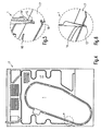
- FIG. 4 shows the rear wall of a tumble dryer 17 with the attached cover 1 according to the invention from FIGS. 1 to 3.
- FIG. 5 and FIG. 8 the detail A from FIG. 4 is shown in perspective.
- the cover 1 is not yet mounted and spaced from the clothes dryer 17.
- In the tumble dryer 17 is at least one Hole 18 for receiving the fastener 13 of the cover 1 executed.
- Fig. 6 and Fig. 9 show the detail A of Fig. 4 with mounted cover 1.
- the wedge-like designed as a clip or detent fastening means 13 is locked in Fig. 5 in the hole 18 which is designed as a counter-detent.
- the sealing lip 14 is compressed in the assembled state and seals the cover 1 substantially airtight or gas-tight.
- the compressed sealing lip 14 generates a clamping force which pushes the cover 1 away from the tumble dryer 17, thereby preventing a folding of the fastening means 13 in the hole 18 during operation of the tumble dryer.
- the cover 1 is thereby mounted vibration-proof on the washer 17.
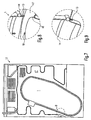
- FIG. 7 shows a further embodiment of the cover 1 according to the invention mounted on a tumble dryer 17.
- FIG. 8 shows a detail B from FIG. 7, wherein the cover 1 is shown with the tumble dryer 17 prior to assembly.
- the embodiment of the cover 1 of Fig. 7 to 9 differs by differently configured fastening means 13 and a correspondingly different hole 18.
- the fastening means 13 shown in Fig. 8 is designed dowel-shaped ,
- the hole 18 is circular and configured as a counter-catch for the fastening means 13.
- Fig. 9 shows the embodiment of the cover 1 according to the invention from FIGS. 7 and 8 in the assembled state. Similar to the embodiment in FIGS. 4 to 6, the sealing lip 14 is compressed in the assembled state with the properties already described above.
- the cover 1 is attached from the outside to a wall 17 '.
- an air supply e.g. with a fan, for generating a gas stream, with which the wet laundry is dried.
- the walls 17 ' are attached to a base frame, for example.
- the cover 1 forms with the wall 17 'in the operation of the clothes dryer 17 from the gas flow through the flow channel, through which the gas stream in the direction of the laundry to be dried can be conducted.
- the cover 1 may alternatively be designed with a flange surface instead of the sealing lip 14. This flange can both the attachment of the cover. 1 serve on a tumble dryer as well as a sealing surface opposite the tumble dryer.
- a sealant is applied to the flange surface during assembly of the cover 1 on the dryer a flange on the surface.
- the cover 1 can be attached to the tumble dryer by the sealant and simultaneously sealed.
- the sealing of the cover according to the invention with respect to the tumble dryer can alternatively be designed as a labyrinth seal.
Abstract
Description
Die Erfindung betrifft eine Abdeckung für einen Wäschetrockner, durch den im Betrieb ein Gasstoffstrom zum Trocknen feuchter Wäsche erwärmbar ist, wobei die Abdeckung als wenigstens ein Abschnitt einer Außenwand, insbesondere einer Rückwand, am Wäschetrockner anbringbar ausgestaltet und von der Abdeckung ein von dem Gasstoffstrom durchströmbarer Kanal wenigstens abschnittsweise ausgebildet ist.The invention relates to a cover for a tumble dryer, through which a gaseous stream for drying damp laundry can be heated in operation, wherein the cover designed as at least a portion of an outer wall, in particular a rear wall, attachable to the tumble dryer and the cover of a flow-through by the gas flow channel at least partially formed.
Üblicherweise werden Wäschetrockner hergestellt, indem eine drehbare Wäschetrommel mit einem Antrieb zusammen mit einer Luftzufuhr und Heizelementen für die Luftzufuhr an einem Grundgestell befestigt und anschließend die Wände am Grundgestell montiert werden. Von der Luftzufuhr wird der Gasstoffstrom zum Trocknen der Wäsche durch einen Kanal geleitet, in dem der Gasstoffstrom gleichzeitig durch das Heizelement erwärmt wird. Dieser Kanal befindet sich nach dem Anbringen der Wände im Inneren des Wäschetrockners und wird zumindest abschnittsweise von einer Wand, typischerweise der Rückwand des Wäschetrockners begrenzt.Typically, clothes dryers are made by attaching a rotatable laundry drum with a drive together with an air supply and heating elements for air supply to a base frame and then the walls are mounted on the base frame. From the air supply, the gas stream is passed to dry the laundry through a channel in which the gas stream is heated simultaneously by the heating element. This channel is located after attaching the walls inside the tumble dryer and is at least partially limited by a wall, typically the rear wall of the tumble dryer.
Solche Wäschetrockner mit Heizelementen sind in der EP-A-0 344 549 und der EP-A-0 352 499 beschrieben. Bei diesen Wäschetrocknern sind die Heizelemente in einem innerhalb des Wäschetrockners angeordneten Waschbottichs vom Gasstoffstrom umströmbar angebracht.Such clothes dryers with heating elements are described in EP-A-0 344 549 and EP-A-0 352 499. In these clothes dryers, the heating elements are mounted in a arranged inside the clothes dryer washing tub umströmbar from the gas stream.
Ein weiterer Wäschetrockner mit einem Strömungskanal ist in der EP-A-0 576 825 beschrieben, bei dem ein Heizmittel am Wäschetrockner angeordnet ist.Another tumble dryer with a flow channel is described in EP-A-0 576 825, in which a heating means is arranged on the tumble dryer.
Aufgrund dieser Anordnung ist die Montage von Wäschetrocknern aufwändig und Wartungsarbeiten an der Luftzufuhr und am Heizelement gestalten sich oft schwierig.Due to this arrangement, the installation of tumble dryers is complex and maintenance work on the air supply and the heating element are often difficult.
Angesichts dieser Probleme besteht die Aufgabe der vorliegenden Erfindung darin, die Herstellungskosten zu senken und die Montagefreundlichkeit des Wäschetrockners zu verbessern.In view of these problems, the object of the present invention is to reduce the manufacturing cost and to improve the ease of installation of the tumble dryer.
Diese Aufgabe wird erfindungsgemäß dadurch gelöst, dass die Abdeckung als Heizeinheit ausgestaltet ist, in der wenigstens ein Heizelement von dem Gasstoffstrom im Betrieb des Wäschetrockners umströmbar integriert ist.This object is achieved in that the cover is designed as a heating unit in which at least one heating element of the gas stream in the operation of the tumble dryer is umströmbar integrated.
Diese Lösung ist konstruktiv einfach und hat den Vorteil, dass die Abdeckung als Heizeinheit vormontiert werden kann und einen gegenüber dem Stand der Technik leichteren Ein- und Ausbau des wenigstens einen Heizelementes ermöglicht. Dadurch lassen sich der Montageaufwand und damit auch die Herstellkosten des Wäschetrockners reduzieren.This solution is structurally simple and has the advantage that the cover can be pre-assembled as a heating unit and compared to the prior art easier installation and removal of at least one heating element allows. As a result, the assembly costs and thus also the production costs of the tumble dryer can be reduced.
Durch die erfindungsgemäße Ausgestaltung der Abdeckung als Heizeinheit wird das Heizelement bereits beim Abnehmen der Abdeckung gleichzeitig mitausgebaut und ist dadurch gut zugänglich.Due to the inventive design of the cover as a heating unit, the heating element is already mitausgebaut already when removing the cover and is therefore easily accessible.
Darüber hinaus kann durch die erfindungsgemäße Lösung auf ein separat im Wäschetrockner zu installierendes Heizelementgehäuse verzichtet werden, wie es bei Wäschetrocknern aus dem Stand der Technik verwendet wird. Hierdurch wird Material eingespart, wodurch sich die Herstellkosten des Wäschetrockners weiter reduzieren. Das Gehäuse des Heizelementes bildet zudem bei bekannten Wäschetrocknern Abrisskanten, wie z.B. an den Durchlässen im Gehäuse. Ohne das Gehäuse werden die bislang in Kauf genommenen Abrisskanten vermieden und dadurch die Luftströmung verbessert. Weiterhin wird bei der erfindungsgemäßen Lösung durch die Doppelfunktion als Abdeckung und Heizelement der bislang im Inneren des Wäschetrockners für die Heizung und die Kanäle verwendete Bauraum frei, so dass z.B. eine größere Wäschetrommel, die üblicherweise vor der Heizeinheit angeordnet ist, verwendet werden kann.In addition, can be dispensed with by the inventive solution to a separately installed in the dryer heating element housing, as used in dryers from the prior art. As a result, material is saved, thereby further reducing the production costs of the tumble dryer. The housing of the heating element also forms in known dryers demolition edges, such. at the passages in the housing. Without the housing so far taken into account demolition edges are avoided, thereby improving the flow of air. Furthermore, in the solution according to the invention by the double function as a cover and heating element of the previously used in the interior of the tumble dryer for the heating and the channels space used so that e.g. a larger laundry drum, which is usually arranged in front of the heating unit, can be used.
Die erfindungsgemäße Abdeckung kann durch verschiedene, voneinander unabhängige, jeweils für sich vorteilhafte Ausgestaltungen weiterentwickelt werden. Auf diese Ausgestaltungen und die mit den Ausgestaltungen jeweils verbundenen Vorteile wird im Folgenden kurz eingegangen.The cover of the invention can be further developed by different, mutually independent, each advantageous embodiments. These refinements and the advantages associated with the respective embodiments will be briefly discussed below.
So kann in einer vorteilhaften Ausgestaltung die Abdeckung Befestigungsmittel umfassen, mit denen die Abdeckung von außen an dem Wäschetrockner vorzugsweise lösbar anbringbar ist. Dies hat den Vorteil, dass die Abdeckung leicht und schnell an dem Wäschetrockner montierbar ist. Ferner können die Befestigungsmittel der Abdeckung als Rasten ausgestaltet sein, mit denen die Abdeckung an dem Wäschetrockner vorzugsweise lösbar verrastbar ist. Bei dieser Ausgestaltung kann die Abdeckung noch schneller an dem Wäschetrockner angebracht werden, wodurch sich die Montagezeit und damit die Montagekosten erheblich reduzieren, da Abdeckungen aus dem Stand der Technik mit einer Vielzahl von Schraubverbindungen zeit- und kostenintensiv befestigt werden.Thus, in an advantageous embodiment, the cover may comprise attachment means with which the cover is preferably detachably attachable from the outside to the tumble dryer. This has the advantage that the cover is easily and quickly mounted on the tumble dryer. Furthermore, the fastening means of the cover can be configured as detents, with which the cover on the tumble dryer is preferably releasably latched. In this embodiment, the cover can be attached even faster to the dryer, thereby reducing the assembly time and thus the installation costs significantly, since covers are attached from the prior art with a variety of screw and time-consuming and costly.
Um den in dem Wäschetrockner strömenden Gasstoffstrom nicht nach außen entweichen zu lassen, kann die Abdeckung eine Dichtlippe umfassen, durch welche die Abdeckung im Wesentlichen gasdicht an dem Wäschetrockner anbringbar ist. Die Dichtlippe kann aus einem elastischen Kunststoff hergestellt sein, um Materialtoleranzen sowohl an der Abdeckung als auch an dem Wäschetrockner ausgleichen zu können. Ferner kann die Abdeckung durch eine Labyrinthdichtung abgedichtet werden. Bei der Labyrinthdichtung kann eine weitere Dichtung von einer zusätzlich abdichtenden Labyrinthanordnung umgeben sein.In order to prevent the gas stream flowing in the tumble dryer from escaping to the outside, the cover may comprise a sealing lip, through which the cover essentially gas-tight attachable to the tumble dryer. The sealing lip may be made of a resilient plastic material in order to be able to compensate for material tolerances on both the cover and the tumble dryer. Furthermore, the cover can be sealed by a labyrinth seal. In the labyrinth seal, another seal may be surrounded by an additional sealing labyrinth arrangement.
In einer vorteilhaften Ausgestaltung kann die Abdeckung eine Flanschfläche ausbilden, mit der die Abdeckung an dem Wäschetrockner anbringbar ist. Eine Flanschfläche hat den Vorteil, dass sie relativ großflächig ausgestaltet werden kann und die großflächige Flanschfläche als Dichtfläche oder zum Anbringen von Befestigungsmitteln benutzt werden kann. Die Flanschfläche kann auch als Klebefläche zum Anbringen der Abdeckung an dem Wäschetrockner mit einem Klebstoff benutzt werden.In an advantageous embodiment, the cover can form a flange surface with which the cover can be attached to the tumble dryer. A flange has the advantage that it can be designed relatively large area and the large-area flange can be used as a sealing surface or for attaching fasteners. The flange surface may also be used as an adhesive surface for attaching the cover to the tumble dryer with an adhesive.
Femer kann die Abdeckung in einer weiteren vorteilhaften Ausgestaltung aus einem elektrisch isolierenden Material hergestellt sein. Hierdurch wird das elektrisch betriebene Heizelement isoliert und es kann kein Strom nach außen fließen. Außerdem wird die Gefahr eines elektrischen Schlages beim Berühren der Abdeckung des Wäschetrockners vermieden und geltende Sicherheitsrichtlinien werden eingehalten. Diese Ausgestaltung der erfindungsgemäßen Abdeckung verhindert außerdem ungewünschte elektrische Effekte, wie z. B. die mögliche Verbreitung von Kriechströmen. Hinsichtlich der thermischen und elektrischen Isolation wird bei Wäschetrocknern aus dem Stand der Technik die Heizungseinheit separat in ein Gehäuse gefasst und zusätzlich mit der Rückwand abgedeckt, was im Vergleich zu der erfindungsgemäßen Lösung material- und kostenintensiver ist.Furthermore, in a further advantageous embodiment, the cover can be produced from an electrically insulating material. As a result, the electrically operated heating element is isolated and no current can flow to the outside. In addition, the risk of electric shock when touching the cover of the tumble dryer is avoided and applicable safety guidelines are met. This embodiment of the cover according to the invention also prevents unwanted electrical effects, such. B. the possible spread of leakage currents. With regard to the thermal and electrical insulation, the heating unit is taken separately in a housing in tumble dryers from the prior art and additionally covered with the rear wall, which is material and cost-intensive compared to the inventive solution.
Um die Temperatur des Gasstoffstroms mit dem Heizelement regeln zu können, kann die als Heizeinheit ausgestaltete Abdeckung wenigstens einen Messfühler umfassen, mit dem die Temperatur des Gasstoffstroms messbar ist. Hierdurch kann der Gasstoffstrom beispielsweise vor oder auch hinter dem Heizelement gemessen werden, um die Energiezufuhr des Heizelementes zu regeln und dadurch den Gasstoffstrom optimal zu beheizen. Ein Messfühler kann auch als Schutzthermostat des Heizelementes verwendet werden und so ein Überhitzen des Heizelements verhindern. Der Messfühler kann beispielsweise im Bereich des Kanals angeordnet sein.In order to be able to regulate the temperature of the gas stream with the heating element, the cover designed as a heating unit can comprise at least one measuring sensor with which the temperature of the gas stream can be measured. In this way, the gas stream can be measured, for example, before or behind the heating element in order to regulate the energy supply of the heating element and thereby optimally heat the gas stream. A sensor can also be used as a protective thermostat of the heating element and thus prevent overheating of the heating element. The sensor may be arranged, for example, in the region of the channel.
Ein Problem der heutigen Wäschetrockner besteht darin, dass aufgrund des begrenzten Bauraums im Inneren des Wäschetrockners die Wärmeenergie des Heizelements leicht nach außen geleitet wird. Dies führt zum einen zu einem niedrigen Wirkungsgrad bei der Aufheizung des Gasstoffstroms. Zum anderen besteht die Gefahr, dass sich die Außenflächen des Wäschetrockners so stark erhitzen, dass sich ein Benutzer beim Berühren dieser Flächen verbrennen kann.One problem with today's clothes dryers is that due to the limited space inside the tumble dryer, the heat energy of the heating element is easily conducted to the outside. This leads to a low efficiency in the heating of the gas stream. On the other hand, there is a risk that the outer surfaces of the tumble dryer heat so much that a user can burn when touching these surfaces.
Um die durch das Heizelement erzeugte Wärmeenergie nicht nach außen zu leiten, kann die Abdeckung in einer vorteilhaften Weiterbildung aus einem wärmeisolierenden Material mit geringer Wärmeleitfähigkeit hergestellt sein. Hierdurch wird keine Wärmeenergie verschwendet und außerdem heizt sich die Abdeckung an ihrer Außenseite nicht so stark auf, dass die Gefahr eines Verbrennens beim Berühren der Abdeckung besteht. Dies trägt dazu bei, dass vorgeschriebene Sicherheitsrichtlinien bezüglich der zulässigen Außentemperatur des Wäschetrockners eingehalten werden und insbesondere der Energieverbrauch gesenkt werden. Weiterhin kann die Abdeckung vorzugsweise aus einem temperaturbeständigen Material hergestellt sein. Die Wärmeisolierung kann auch dadurch verbessert werden, dass an Bereichen hoher Temperatur zusätzliche Schutzbereiche aus wärmebeständigen Materialien vorgesehen sind.In order not to direct the heat energy generated by the heating element to the outside, the cover can be made in an advantageous development of a heat-insulating material with low thermal conductivity. As a result, no heat energy is wasted and, moreover, the cover on its outside does not heat up so much that there is a risk of burning when the cover is touched. This contributes to compliance with prescribed safety guidelines with regard to the permissible outside temperature of the tumble dryer and in particular the energy consumption. Furthermore, the cover may preferably be made of a temperature-resistant material. The thermal insulation can also be improved by providing additional protection areas of heat-resistant materials at high-temperature areas.
In einer weiteren vorteilhaften Ausführungsform kann die Heizeinheit einen Wärmeschutzkörper umfassen, der das wenigstens eine Heizelement wenigstens teilweise umgibt und die Umgebung vor dem Wärmeeinfluss sichert. Dies hat den Vorteil, dass ein zusätzlicher Wärmeschutz der Heizeinheit nach außen besteht, um ein ungewolltes Erwärmen der Umgebung der Abdeckung sowohl nach außen und als auch zum Innern des Wäschetrockners zu verhindern. Durch diese Ausführungsform der vorliegenden Erfindung kann auf einfache Weise die nach geltenden Sicherheitsvorschriften für Wäschetrockner zulässige Außentemperatur der Außenwand von etwa 85°C auch bei den in der Heizeinheit herrschenden Innentemperaturen bis zu etwa 600°C gewährleistet werden.In a further advantageous embodiment, the heating unit may comprise a thermal protection body which at least partially surrounds the at least one heating element and secures the environment from the influence of heat. This has the advantage that an additional heat protection of the heating unit to the outside exists to prevent unwanted heating of the environment of the cover both to the outside and to the inside of the clothes dryer. By means of this embodiment of the present invention, the outside temperature of the outside wall of about 85 ° C., which is permissible according to applicable safety regulations for dryers, can be ensured in a simple manner up to about 600 ° C. even in the case of the internal temperatures prevailing in the heating unit.
Ferner kann der Wärmeschutzkörper in einer vorteilhaften Weiterbildung einen von dem Gasstoffstrom durchströmbaren Strömungskanal ausbilden. Durch den Strömungskanal wird der Gasstoffstrom gezielt und unter geringen Verlusten zu dem wenigstens einen Heizelement geleitet, so dass eine effektive Erwärmung des Gasstoffstroms gewährleistet ist. Außerdem wird durch den Strömungskanal der Gasstoffstrom nach dem Durchströmen der Heizeinheit unter geringen Strömungsverlusten in die Wäschetrommel des Wäschetrockners hineingeleitet, wodurch die erzeugte Wärmeenergie der Wäsche effektiv und energiesparend zugeführt wird. Um einen guten Wärmeübergang zwischen dem Heizelement und dem Gasstoffstrom zu erreichen, kann das Heizelement im Strömungskanal angeordnet sein.Furthermore, in an advantageous development, the heat protection body can form a flow channel through which the gas stream can flow. Through the flow channel of the gas stream is targeted and with low losses to the at least one Conducted heating element, so that an effective heating of the gas flow is ensured. In addition, the gas flow is passed through the flow channel after flowing through the heating unit with low flow losses in the laundry drum of the clothes dryer, whereby the generated heat energy of the laundry is supplied effectively and energy-saving. In order to achieve a good heat transfer between the heating element and the gas stream, the heating element can be arranged in the flow channel.
Um die Wärmeenergie des Heizelementes nicht in die Umgebung abzuleiten, kann der Wärmeschutzkörper aus einem wärmeisolierenden und temperaturbeständigen Material, vorzugsweise einem Kunststoff, hergestellt sein.In order not to dissipate the heat energy of the heating element in the environment, the heat shield can be made of a heat-insulating and temperature-resistant material, preferably a plastic.
Der Wärmeschutzkörper kann auch aus einem Metall hergestellt werden. Der metallische Wärmeschutzkörper hat den Vorteil, dass er einfach und kostengünstig, beispielsweise durch Tiefziehen, hergestellt werden kann. Außerdem kann der Wärmeschutzkörper aus einem korrosionsbeständigem Material, z. B. einem CrNi-Stahl, hergestellt sein, um eine Korrosion des Wärmeschutzkörpers, der in dem Wäschetrockner beispielsweise Feuchtigkeit ausgesetzt ist, zu verhindern.The heat shield can also be made of a metal. The metallic heat shield has the advantage that it can be easily and inexpensively, for example by deep drawing, can be produced. In addition, the heat shield of a corrosion resistant material, for. As a CrNi steel, to prevent corrosion of the heat shield, which is exposed in the tumble dryer, for example, moisture.
Ferner kann die Abdeckung weitere Befestigungsmittel umfassen, an denen der Wärmeschutzkörper lösbar angebracht ist. Dies hat den Vorteil, dass der Wärmeschutzkörper leicht und ohne zusätzliche Befestigungsmittel an der Abdeckung montiert werden kann und sich somit die Montage- und Herstellkosten der Heizeinheit reduzieren.Further, the cover may include further attachment means to which the heat shield is releasably attached. This has the advantage that the heat protection body can be mounted on the cover easily and without additional fastening means and thus reduce the assembly and manufacturing costs of the heating unit.
In einer weiteren vorteilhaften Ausgestaltung kann in der Abdeckung wenigstens ein Kontaktelement integriert sein, mit dem die Heizeinheit an einem maschinenseitigen Gegenkontakt elektrisch anschließbar ist. Dies hat den Vorteil, dass die Heizeinheit vor der Anbringung an den Wäschetrockner einfach an einer Spannungsquelle anschließbar ist. Femer kann das Kontaktelement als ein Teil einer Steckerverbindung ausgestaltet sein, wodurch ein schneller und einfacher Anschluss des Kontaktelements gewährleistet ist. Der Anschluss der Heizeinheit kann auch durch ein einziges, möglicherweise genormtes Steckerelement geschehen, wodurch sich die erforderliche Anschlusszeit weiter reduziert. Hierbei werden die unterschiedlichen elektrischen Leitungen des wenigstens einen Heizelements und des wenigstens einen Messfühlers in dem einen Steckerelement angeschlossen. Das Steckerelement wird in ein entsprechendes Gegensteckerelement des Wäschetrockners eingesteckt.In a further advantageous embodiment, at least one contact element can be integrated in the cover, with which the heating unit can be electrically connected to a counterpart contact on the machine side. This has the advantage that the heating unit can be simply connected to a voltage source before being attached to the tumble dryer. Furthermore, the contact element can be designed as part of a plug connection, whereby a quick and easy connection of the contact element is ensured. The connection of the heating unit can also be done by a single, possibly standardized plug element, which further reduces the required connection time. In this case, the different electrical lines of the at least one heating element and the at least one sensor in the one plug element connected. The plug element is inserted into a corresponding mating plug element of the tumble dryer.
Ferner kann das Kontaktelement in einer weiteren vorteilhaften Ausgestaltung in der Abdeckung integriert sein, um die Anbringung der Abdeckung an dem Wäschetrockner weiter zu vereinfachen.Furthermore, the contact element can be integrated in a further advantageous embodiment in the cover to further simplify the attachment of the cover to the tumble dryer.
Um die Abdeckung kostengünstig und mit einer hohen Formgenauigkeit herstellen zu können, kann die Abdeckung als behälterförmiges Gehäuse ausgeformt sein, das als ein Spritzgussteil ausgestaltet ist. Spritzgussteile können mit einer hohen Maßgenauigkeit hergestellt werden und sind, wenn sie in hohen Stückzahlen produziert werden, sehr kostengünstig. Durch die behälterförmige Ausgestaltung des Gehäuses, z.B. mit einer hohen Umrandung, ist die Abdeckung trotz der angeordneten Einzelteile der Heizeinheit an einer planen Wand anbringbar und bildet dabei den von dem Gasstoffstrom durchströmbaren Kanal aus.In order to produce the cover inexpensively and with a high dimensional accuracy, the cover may be formed as a container-shaped housing, which is designed as an injection molded part. Injection molded parts can be produced with a high degree of dimensional accuracy and, when produced in large quantities, are very cost-effective. Due to the container-shaped design of the housing, e.g. With a high border, the cover is despite the arranged individual parts of the heating unit attached to a flat wall, thereby forming the flow through the gas flow channel.
In einer vorteilhaften Weiterbildung kann das behälterförmige Gehäuse als ein Kunststoffteil ausgestaltet sein, das abschnittsweise mit wenigsten einem Schutzbereich aus einem anderen Material, vorzugsweise einem Metallblech, versehen ist. Durch den Verbund von Kunststoff mit anderen Materialien werden beispielsweise die Stabilität und die Temperaturbeständigkeit des Gehäuses verbessert. Hierbei können die anderen Materialien sowohl auf das Kunststoffteil als auch schichtartig im Kunststoffteil angeordnet sein. Ferner kann der wenigstens eine Schutzbereich in einem Bereich angeordnet sein, in dem im Betrieb eine hohe Temperatur auftritt. Hierdurch wird die Wärmeisolierung und Temperaturbeständigkeit des Gehäuses verbessert.In an advantageous development, the container-shaped housing can be configured as a plastic part, which is provided in sections with at least one protective area made of another material, preferably a metal sheet. By combining plastic with other materials, for example, the stability and temperature resistance of the housing are improved. In this case, the other materials can be arranged both on the plastic part as well as a layer in the plastic part. Furthermore, the at least one protection region can be arranged in a region in which a high temperature occurs during operation. This improves the thermal insulation and temperature resistance of the housing.
In einer weiteren vorteilhaften Ausgestaltung kann die Abdeckung von außen an den Wäschetrockner anbringbar sein. Dies hat den Vorteil, dass die so ausgestaltete Abdeckung besonders leicht an dem Wäschetrockner zu montieren ist.In a further advantageous embodiment, the cover can be attached to the tumble dryer from the outside. This has the advantage that the cover designed in this way is particularly easy to mount on the tumble dryer.
Die Erfindung betrifft neben der oben beschriebenen Abdeckung und deren Ausgestaltungen auch einen Wäschetrockner zum Trocknen feuchter Wäsche mit einem Gasstoffstrom, wobei der Wäschetrockner mit Wänden, einer Luftzufuhr und mit einem von dem Gasstoffstrom durchströmbaren Kanal ausgeführt ist. Um die Montage des Wäschetrockners zu erleichtern, umfasst der Wäschetrockner eine Abdeckung nach einer der oben genannten Ausführungsformen und wird der Kanal wenigstens abschnittsweise von der Abdeckung gebildet.The invention relates not only to the cover described above and its embodiments, but also to a tumble dryer for drying damp laundry with a gas stream, wherein the tumble dryer is designed with walls, an air supply and a channel through which the gas stream can flow. To the assembly of the tumble dryer To facilitate the tumble dryer comprises a cover according to one of the above embodiments and the channel is at least partially formed by the cover.
Die Erfindung betrifft neben den oben erläuterten Vorrichtungen und ihren weiteren Ausgestaltungen auch ein Verfahren zum Zusammenbau eines Wäschetrockners durch den im Betrieb ein Gasstoffstrom zum Trocknen feuchter Wäsche erwärmbar ist. Um die nötige Montagezeit des Wäschetrockners zu verkürzen, ist erfindungsgemäß vorgesehen, dass eine Heizeinheit durch Anbringen wenigstens eines im Betrieb des Wäschetrockners vom Gasstrom umströmbaren Heizelements an einer Abdeckung vormontiert und ein durchströmbarer Kanal ausgebildet wird und dass die Abdeckung am Wäschetrockner als wenigstens ein Abschnitt der Außenwand des Wäschetrockners angebracht und der Kanal mit einer Luftzufuhr des Wäschetrockners verbunden wird.The invention relates not only to the above-described devices and their further embodiments, but also to a method for assembling a tumble dryer through which a gaseous stream for drying damp laundry can be heated during operation. In order to shorten the necessary assembly time of the tumble dryer, the invention provides that a heating unit is mounted by attaching at least one during operation of the tumble dryer flowable by the gas flow heater on a cover and a flow-through channel is formed and that the cover on the dryer as at least a portion of the outer wall attached to the tumble dryer and the channel is connected to an air supply of the clothes dryer.
In einer vorteilhaften Weiterbildung kann die Abdeckung durch lösbares oder unlösbares Verrasten an der Wand angebracht werden, um die Montage des Wäschetrockners zu vereinfachen. Aus gleichem Grund kann ein Kontakt zur Stromversorgung des Heizelements beim Anbringen der Abdeckung an der Wand gleichzeitig geschlossen werden. Ferner kann der Kanal während des Anbringens der Abdeckung an der Wand des Wäschetrockners gleichzeitig im Wesentlichen gasdicht abgedichtet werden.In an advantageous development, the cover can be attached to the wall by releasable or non-releasable latching in order to simplify the installation of the tumble dryer. For the same reason, a contact to the power supply of the heating element when attaching the cover to the wall can be closed simultaneously. Furthermore, during the attachment of the cover to the wall of the tumble dryer, the channel can be sealed in a substantially gastight manner at the same time.
Im Folgenden wird die Erfindung beispielhaft mit Bezug auf die beigefügten Zeichnungen erläutert. Die unterschiedlichen Merkmale können dabei unabhängig voneinander kombiniert werden, wie dies oben bei den einzelnen vorteilhaften Ausgestaltungen bereits dargelegt wurden.The invention will now be described by way of example with reference to the accompanying drawings. The different features can be combined independently of each other, as already explained above in the individual advantageous embodiments.
Es zeigen:
- Fig. 1
- eine Perspektivansicht einer beispielhaften Ausführungsform der erfindungsgemäßen Abdeckung schematisch von oben;
- Fig. 2
- eine perspektivische Explosionsdarstellung der erfindungsgemäßen Abdeckung aus Fig. 1 schematisch von unten;
- Fig. 3
- eine perspektivische Explosionsdarstellung der erfindungsgemäßen Abdeckung aus Fig. 1 schematisch von oben;
- Fig. 4
- eine Ausführungsform der erfindungsgemäßen Abdeckung angebracht an der Rückwand eines Wäschetrockners;
- Fig. 5
- eine Detailansicht der erfindungsgemäßen Abdeckung aus Fig. 4 vor ihrer Anbringung an dem Wäschetrockner;
- Fig. 6
- eine Detailansicht der erfindungsgemäßen Abdeckung aus Fig. 4 nach ihrer Anbringung an dem Wäschetrockner;
- Fig. 7
- eine weitere Ausführungsform der erfindungsgemäßen Abdeckung angebracht an der Rückwand eines Wäschetrockners;
- Fig. 8
- eine Detailansicht der erfindungsgemäßen Abdeckung aus Fig. 7 vor ihrer Anbringung an dem Wäschetrockner;
- Fig. 9
- eine Detailansicht der erfindungsgemäßen Abdeckung aus Fig. 7 nach ihrer Anbringung an dem Wäschetrockner;
- Fig. 1
- a perspective view of an exemplary embodiment of the cover according to the invention schematically from above;
- Fig. 2
- an exploded perspective view of the cover according to the invention of Figure 1 schematically from below.
- Fig. 3
- an exploded perspective view of the cover according to the invention of Figure 1 schematically from above.
- Fig. 4
- an embodiment of the cover according to the invention attached to the rear wall of a tumble dryer;
- Fig. 5
- a detailed view of the cover according to the invention of Figure 4 before being attached to the tumble dryer.
- Fig. 6
- a detailed view of the cover of the invention of Figure 4 after its attachment to the dryer.
- Fig. 7
- a further embodiment of the cover according to the invention mounted on the rear wall of a tumble dryer;
- Fig. 8
- a detail view of the cover of the invention of Figure 7 prior to its attachment to the dryer.
- Fig. 9
- a detailed view of the cover of the invention of Figure 7 after its attachment to the dryer.
Zunächst wird der allgemeine Aufbau der erfindungsgemäßen Abdeckung 1 mit Bezug auf die Fig. 1 bis 3 und die darin dargestellte beispielhafte Ausführungsform beschrieben.First, the general structure of the
Die als Heizeinheit ausgestaltete Abdeckung 1 umfasst ein Gehäuse 2, einen Wärmeschutzkörper 3 und mehrere Heizelemente 4. Die in den Fig. 1 bis 3 beispielhaft dargestellte Ausführungsform der erfindungsgemäßen Abdeckung enthält vier nebeneinander und übereinander angeordnete Heizelemente 4. Die Heizelemente 4 werden durch zwei seitlich angeordnete Trägerplatten 5 als eine einstückige Moduleinheit zusammengehalten. Die Heizelemente 4 werden relativ zueinander so positioniert, dass ein vorbeiströmender Gasstoffstrom optimal erwärmt werden kann.The
Die Heizelemente 4 sind innerhalb des Wärmeschutzkörpers 3 angeordnet, der die Heizelemente von der Umgebung thermisch isoliert und gleichzeitig einen Strömungskanal ausbildet, um einen Gasstoffstrom, vorzugsweise einen Luftstrom, möglichst gut an den Heizelementen 4 vorbeizuleiten. Der Wärmeschutzkörper 3 weist hierzu eine Einlassöffnung 6 und eine Auslassöffnung 7 auf. Der zu erwärmende Luftstrom strömt an der Einlassöffnung in den Wärmeschutzkörper 3 hinein und wird durch die Form des Wärmeschutzkörpers 3 durch die Heizelemente 4 hindurch bzw. an diesen entlang geleitet, wodurch sich der Luftstrom erwärmt. Der aufgewärmte Luftstrom strömt an der Auslassöffnung 7 aus dem Wärmeschutzkörper 3 hinaus.The
Um einen guten Wärmeschutz zu erreichen, ist der Wärmeschutzkörper 3 aus einem korrosionsbeständigen Metallblech, beispielsweise einem CrNi-Stahlblech, hergestellt. Die wärmeabschirmende Wirkung des Wärmeschutzkörpers 3 ist besonders wichtig, weil im Innem des Wärmeschutzkörpers im Bereich der Heizelemente 4 Temperaturen bis zu 600°C auftreten können. Hierbei darf die Oberflächentemperatur an der Außenseite einen zulässigen Wert, beispielsweise nach einer VDE-Richtlinie 85°C, nicht überschreiten. Erschwerend wirkt bei der Wärmeisolierung, dass der zur Verfügung stehende Bauraum äußerst begrenzt ist. Um die Wärmeisolierung zu verstärken, kann der Wärmeschutzkörper mit einer reflektierenden Oberfläche ausgeführt sein: Der Wärmeschutzkörper 9 weist zudem eine geringe Wärmeleitfähigkeit auf, so dass die extrem hohe Temperatur aus dem Bereich der Heizelemente 4 nicht an die äußere Oberfläche der Abdeckung 1 übertragen werden kann. Somit kann die äußere Oberfläche der Abdeckung 1 von einem Bediener ohne die Gefahr einer Verbrennung berührt werden.In order to achieve a good thermal protection, the
Damit die Abdeckung 1 mit dem darin vormontierten Heizelement 4 leicht vormontiert werden kann, ist der Wärmeschutzkörper 3 beispielsweise zweiteilig ausgeführt. Er besteht aus einem unteren Teil 9 und einem oberen Teil 10. Der untere Teil 9 ist in der beispielhaften Ausführungsform in Fig. 1 bis 3 ein ausgestanztes Blechteil an dem durch Biegen der Leitkörper 8 ausgeformt ist. Der obere Teil 10 des Wärmeschutzkörpers 3 ist bei der Ausgestaltung in Fig. 1 bis 3 durch Tiefziehen hergestellt worden. In dem oberen Teil 10 des Wärmeschutzkörpers 3 ist neben der Einlassöffnung 6 und der Auslassöffnung 7 jeweils mindestens eine Aussparung 11 ausgeformt, in der mindestens ein Temperatursensor 12 angebracht ist.So that the
Durch die Temperatursensoren 12 kann die Erwärmung des Luftstroms innerhalb der Abdeckung 1 gemessen und die Heizleistung der Heizelemente 4 geregelt werden. Mit der gemessenen Temperatur bzw. Temperaturdifferenz des Luftstroms kann insbesondere ein Regelkreis aufgebaut werden, mit dem die Heizelemente 4 angesteuert werden und die Temperatur des Luftstroms geregelt wird. Zur Verbesserung des Regelkreises können auch mehr als zwei Temperatursensoren eingesetzt werden, um die Temperatur an verschiedenen Stellen des Luftstroms zu ermitteln. So kann beispielsweise die Temperatur des Luftstroms vor und hinter dem Heizelement 4 gemessen werden. Außerdem kann ein weiterer Temperatursensor in der Nähe der Heizelemente 4 als ein Schutzthermostat angeordnet sein, um einen zu starken Temperaturanstieg der Heizelemente 4 zu erkennen und damit ein Überhitzen zu verhindern. Der Wärmeschutzkörper 3 mit den Heizelementen 4 ist an dem Gehäuse 2 angebracht.By the
Das Gehäuse 2 ist mit Befestigungsmitteln 13 zum lösbaren Anbringen der Abdeckung 1 an einem Wäschetrockner versehen. Die Befestigungsmittel 13 werden im Folgenden noch genauer beschrieben. Die Abdeckung 1 umfasst des Weiteren eine Dichtlippe 14, durch die die Abdeckung 1 im Wesentlichen gasdicht an dem Wäschetrockner anbringbar ist. Hierdurch wird verhindert, dass ein Teil des erwärmten Luftstroms nach außen abgegeben wird. Das Gehäuse 2 der in den Fig. 1 bis 3 dargestellten Ausführungsform ist aus einem wärmeisolierenden Kunststoff hergestellt. Dies ist vorteilhaft, damit die hohe Temperatur im Bereich der Heizelemente 4 nicht an die äußere Oberfläche der Abdeckung 1 aus den oben genannten Gründen übertragen wird. Des Weiteren ist das Gehäuse 2 aus einem elektrisch isolierenden Kunststoff hergestellt, um die Heizelemente 4 gegenüber den restlichen Teilen des Wäschetrockners und auch nach außen elektrisch zu isolieren. Des Weiteren wird durch die Ausführung des Gehäuses 2 aus einem elektrisch isolierenden Material einem Verbreiten von Kriechströmen entgegengewirkt.The
An den Stellen hoher Temperatur kann bereichsweise ein temperaturbeständiges Material z. B. ein Metallblechteil am Gehäuse 2 angebracht werden, so dass in diesem Schutzbereich das Gehäuse 2 geschützt ist.At the points of high temperature, a temperature-resistant material z. B. a sheet metal part are attached to the
Wie in den Fig. 1 bis 3 dargestellt ist das Gehäuse 2 behälterförmig ausgeführt und weist eine umlaufende Behälterwand 2a auf, die einen Innenraum 2b umschließt. Hier durch ist die erfindungsgemäße Abdeckung 1, in welcher der Wärmeschutzkörper 3 mit den Heizelementen 4 im Innenraum 2b des Gehäuses 2 angebracht sind und nicht über die Behälterwand 2a hinausstehen, an eine Wand 17' eines Wäschetrockners 17 anbringbar. Wie dargestellt ist, kann die Wand 17' plan sein.As shown in FIGS. 1 to 3, the
Das Gehäuse 2 der in den Fig. 1 bis 3 dargestellten Ausführungsform der erfindungsgemäßen Abdeckung 1 ist als ein Spritzgussteil ausgeführt. Die Herstellung des Gehäuses im Spritzgießverfahren hat den Vorteil, dass eine große Stückzahl kostengünstig bei hoher Formgenauigkeit hergestellt werden kann.The
Die Abdeckung 1 umfasst weiterhin wenigstens ein Kontaktelement 15, durch das die Abdeckung 1 mit ihren Heizelementen 4 und Temperatursensoren 12 elektrisch anschließbar ist. Das in den Fig. 1 bis 3 dargestellte Kontaktelement 15 ist beispielsweise als standardisierter Stecker ausgeführt und in dem Gehäuse 2 integriert. Ein entsprechender Gegenstecker befindet sich an dem Wäschetrockner, so dass sich in der Montageposition der Abdeckung 1 eine Steckverbindung von selbst herstellt. Über das Kontaktelement 15 sind sowohl die Heizelemente 4 als auch die Temperatursensoren 12 elektrisch anschließbar. Dies hat den Vorteil, dass nur ein Kontaktelement zum elektrischen Anschließen sämtlicher Teile der Abdeckung 1 nötig ist.The
Das Gehäuse 2 hat weitere Befestigungsmittel 16, an denen der Wärmeschutzkörper 3 lösbar angebracht ist. Bei der Montage der Abdeckung 1 kann der untere Teil 9 des Wärmeschutzkörpers 3 in die als Rastmittel ausgeführten weiteren Befestigungsmittel 16 eingerastet werden. Danach wird die vormontierte Moduleinheit aus Heizelementen 4 und Trägerplatten 5 auf den unteren Teil 9 aufgesetzt. Abschließend wird der obere Teil 10 des Wärmeschutzkörpers 3 aufgesetzt und ebenfalls an den weiteren Befestigungsmitteln 16 eingerastet. Der Wärmeschutzkörper 3 kann Befestigungsmittel zur Fixierung der Heizelemente 4 innerhalb des Wärmeschutzkörpers 3 enthalten. In der in den Fig. 1 bis 3 dargestellten Ausführungsform sind die weiteren Befestigungsmittel 16 gleichzeitig in Form von Rippen zur Verstärkung der Stabilität des Gehäuses 2 ausgestaltet.The
Fig. 4 zeigt die Rückwand eines Wäschetrockners 17 mit der angebauten erfindungsgemäßen Abdeckung 1 aus den Fig. 1 bis 3. In Fig. 5 und Fig. 8 ist das Detail A aus Fig. 4 perspektivisch dargestellt. Hierbei ist die Abdeckung 1 noch nicht montiert und von dem Wäschetrockner 17 beabstandet. In dem Wäschetrockner 17 ist mindestens ein Loch 18 zur Aufnahme des Befestigungsmittels 13 der Abdeckung 1 ausgeführt. Fig. 6 und Fig. 9 zeigen das Detail A aus Fig. 4 mit montierter Abdeckung 1. Das keilartig als Clips oder Raste ausgeführte Befestigungsmittel 13 ist in Fig. 5 in dem Loch 18, das als eine Gegenraste ausgeführt ist, eingerastet. Die Dichtlippe 14 ist in montiertem Zustand zusammengedrückt und dichtet die Abdeckung 1 im Wesentlichen luftdicht bzw. gasdicht ab. Außerdem erzeugt die zusammengedrückte Dichtlippe 14 eine Spannkraft, die die Abdeckung 1 von dem Wäschetrockner 17 wegdrückt, wodurch im Betrieb des Wäschetrockners ein Klappem des Befestigungsmittels 13 in dem Loch 18 verhindert wird. Die Abdeckung 1 ist dadurch vibrationsfest an dem Wäschtrockner 17 angebracht.4 shows the rear wall of a
Fig. 7 zeigt eine weitere Ausführungsform der erfindungsgemäßen Abdeckung 1 montiert an einem Wäschetrockner 17. Fig. 8 zeigt ein Detail B aus Fig. 7, wobei die Abdeckung 1 vor der Montage mit dem Wäschetrockner 17 dargestellt ist. Im Vergleich zu der Ausführungsform der Abdeckung aus den Fig. 4 bis 6 unterscheidet sich die Ausführungsform der Abdeckung 1 der Fig. 7 bis 9 durch anders ausgestaltete Befestigungsmittel 13 und ein entsprechend anderes Loch 18. Das in Fig. 8 dargestellte Befestigungsmittel 13 ist dübelförmig ausgeführt. Das Loch 18 ist kreisförmig und als Gegenraste für das Befestigungsmittel 13 ausgestaltet. Fig. 9 zeigt die Ausführungsform der erfindungsgemäßen Abdeckung 1 aus den Fig. 7 und 8 in montiertem Zustand. Ähnlich wie bei der Ausführungsform in den Fig. 4 bis 6 ist die Dichtlippe 14 in montiertem Zustand zusammengedrückt mit den oben bereits beschriebenen Eigenschaften.FIG. 7 shows a further embodiment of the
Bei dem in Fig. 5 und 7 beispielhaft dargestellten erfindungsgemäßen Wäschetrocknern 17 ist die Abdeckung 1 von außen an einer Wand 17' angebracht. Im Innem des Wäschetrockners 17 befindet sich eine Luftzufuhr, z.B. mit einem Ventilator, zum Erzeugen eines Gasstoffstroms, mit dem die feuchte Wäsche getrocknet wird. Die Wände 17' sind beispielsweise an einem Grundgestell angebracht. Die Abdeckung 1 bildet mit der Wand 17' einen im Betrieb des Wäschetrockners 17 von dem Gasstoffstrom durchströmten Kanal aus, durch den der Gasstoffstrom in Richtung der zu trocknenden Wäsche leitbar ist.In the
Die Fig. 1-3 zeigen eine mögliche Ausführungsform der erfindungsgemäßen Abdeckung 1. Die Abdeckung 1 kann alternativ mit einer Flanschfläche anstelle der Dichtlippe 14 ausgeführt sein. Diese Flanschfläche kann sowohl der Befestigung der Abdeckung 1 an einem Wäschetrockner als auch als Dichtfläche gegenüber dem Wäschetrockner dienen. Zur Befestigung der Abdeckung 1 können z. B. Bohrungen in der Flanschfläche ausgeführt sein. In den Bohrungen können z. B. Schrauben oder Nieten zur Befestigung der Abdeckung 1 an dem Wäschetrockner angeordnet sein. Zum Abdichten dieser Ausfühnrngsform der erfindungsgemäßen Abdeckung wird auf die Flanschfläche bei der Montage der Abdeckung 1 an dem Wäschetrockner ein Dichtmittel auf die Flanschfläche aufgetragen. Bei der Verwendung eines klebenden Dichtmittels kann die Abdeckung 1 durch das Dichtmittel an dem Wäschetrockner angebracht und gleichzeitig abgedichtet werden.1-3 show a possible embodiment of the
Die Abdichtung der erfindungsgemäßen Abdeckung gegenüber dem Wäschetrockner kann alternativ auch als Labyrinthdichtung ausgeführt sein.The sealing of the cover according to the invention with respect to the tumble dryer can alternatively be designed as a labyrinth seal.
Claims (24)
- Cover (1) for a laundry dryer (17), by means of which in operation a gaseous material stream may be warmed for the drying of damp laundry, wherein the cover (1) is formed so as to be applied as at least one section of an outer wall, in particular a rear wall, the laundry dryer (17) and a channel is formed at least in sections by the cover (1) through which channel the gaseous material stream may flow, characterised in that the cover (1) is formed as a heating unit in which at least one heating element (4) is incorporated in such a manner that the gaseous material stream may flow around the same during operation of the laundry dryer (17).
- Cover (1) according to claim 1, characterised in that the cover (1) comprises fixing means (13) with which the cover (1) may be applied to the laundry dryer (17) from the outside.
- Cover (1) according to claim 2, characterised in that the fixing means (13) are formed as catches with which the cover (1) may be locked to the laundry dryer (17).
- Cover (1) according to claim 2 or 3, characterised in that the fixing means (13) are formed to be detachable more than once.
- Cover (1) according to one of the preceding claims, characterised in that the cover (1) comprises a sealing lip (14) by means of which the cover (1) may be applied to the laundry dryer (17) substantially in a gas-tight manner.
- Cover (1) according to one of the preceding claims, characterised in that the cover (1) comprises a labyrinth seal, by means of which the cover (1) may be applied to the laundry dryer (17) substantially in a gas-tight manner.
- Cover (1) according to one of the preceding claims, characterised in that the cover (1) is manufactured from a heat-insulating material.
- Cover (1) according to one of the preceding claims, characterised in that the cover (1) is manufactured from a temperature-resistant material.
- Cover (1) according to one of the preceding claims, characterised in that the cover (1) is manufactured from an electrically insulating material.
- Cover (1) according to one of the preceding claims, characterised in that the cover (1) formed as a heating unit comprises at least one temperature sensor (12) with which the temperature of the gaseous material stream may be measured.
- Cover (1) according to one of the preceding claims, characterised in that the heating unit comprises a heat-protection body (3) which at least partly sunrounds the at least one heating element (4).
- Cover (1) according to claim 11, characterised in that the heat-protection body (3) forms a flow channel through which the gaseous material stream may flow.
- Cover (1) according to claim 11 or 12, characterised in that the heat protection body (3) is manufactured from a temperature-resistant material.
- Cover (1) according to one of the preceding claims, characterised in that at least one contact element (15) may be incorporated, with which the heating unit may be electrically connected to a counter-contact on the machine side.
- Cover (1) according to claim 14, characterised in that the contact element (15) is formed as part of a plug-in connection.
- Cover (1) according to claim 14 or 15, characterised in that the contact element (15) is incorporated in the cover (1).
- Cover (1) according to one of the preceding claims, characterised in that the cover (1) comprises a container-like housing (2), which is formed as an injection moulded part.
- Cover (1) according to claim 17, characterised in that the housing (2) is formed as a synthetic materials part, which is provided in sections with at least one protective region composed of a different material.
- Cover (1) according to claim 18, characterised in that the at least one protective region is disposed in a region in which a high temperature occurs during operation.
- Laundry dryer (17) for drying damp laundry with a gaseous material stream, the laundry dryer (17) being formed with walls (17'), an air supply and a channel through which the gaseous material stream may flow, characterised in that the laundry dryer (17) has a cover (1) according to one of claims 1 to 17 and in that the channel is formed by the cover (1) at least in sections.
- Method of assembling a laundry dryer (17) by which a gaseous material stream may be heated during operation in order to dry damp laundry, comprising the following steps:- pre-assembly of a heating unit by applying at least one heating element (4), around which a gaseous material stream may flow during operation of the laundry dryer, to a cover, and formation of a channel capable of carrying a flow;- application of the cover (1) to the laundry dryer (17) as at least a section of the outer wall (17') of the laundry dryer and connection of the channel to an air supply of the laundry dryer (17).
- Method according to claim 21, comprising the following step:- application of the cover to the wall by detachable or non-detachable locking.
- Method according to claim 21 or 22, comprising the following step:- simultaneous closing of a contact for supplying current to the heating element upon application of the cover (1) to the wall (17').
- Method according to one of claims 21 to 23, comprising the following step:- simultaneous substantially gas-tight sealing of the channel during application of the cover (1) to the wall (17') of the laundry dryer (17).
Priority Applications (6)
| Application Number | Priority Date | Filing Date | Title |
|---|---|---|---|
| DE50302587T DE50302587D1 (en) | 2003-12-02 | 2003-12-02 | Cover for a tumble dryer and method of assembling it |
| EP03027650A EP1538255B1 (en) | 2003-12-02 | 2003-12-02 | Cover for a laundry dryer and process for its assembly |
| AT03027650T ATE319874T1 (en) | 2003-12-02 | 2003-12-02 | COVER FOR A CLOTHES DRYER AND METHOD FOR ASSEMBLY THEREOF |
| US10/999,813 US8371040B2 (en) | 2003-12-02 | 2004-11-29 | Cover for a clothes dryer and assembling method thereof |
| JP2004346859A JP2005169106A (en) | 2003-12-02 | 2004-11-30 | Cover for clothes dryer, and assembling method thereof |
| KR1020040100094A KR100676007B1 (en) | 2003-12-02 | 2004-12-01 | Cover for a Clothes Dryer and Assembling Method thereof |
Applications Claiming Priority (1)
| Application Number | Priority Date | Filing Date | Title |
|---|---|---|---|
| EP03027650A EP1538255B1 (en) | 2003-12-02 | 2003-12-02 | Cover for a laundry dryer and process for its assembly |
Publications (2)
| Publication Number | Publication Date |
|---|---|
| EP1538255A1 EP1538255A1 (en) | 2005-06-08 |
| EP1538255B1 true EP1538255B1 (en) | 2006-03-08 |
Family
ID=34442935
Family Applications (1)
| Application Number | Title | Priority Date | Filing Date |
|---|---|---|---|
| EP03027650A Revoked EP1538255B1 (en) | 2003-12-02 | 2003-12-02 | Cover for a laundry dryer and process for its assembly |
Country Status (6)
| Country | Link |
|---|---|
| US (1) | US8371040B2 (en) |
| EP (1) | EP1538255B1 (en) |
| JP (1) | JP2005169106A (en) |
| KR (1) | KR100676007B1 (en) |
| AT (1) | ATE319874T1 (en) |
| DE (1) | DE50302587D1 (en) |
Cited By (3)
| Publication number | Priority date | Publication date | Assignee | Title |
|---|---|---|---|---|
| DE102016110023A1 (en) | 2015-11-13 | 2017-05-18 | Dbk David + Baader Gmbh | Heating unit and tumble dryer |
| EP3190228A1 (en) | 2016-01-05 | 2017-07-12 | DBK David + Baader GmbH | Heating device for tumble dryer and tumble dryer |
| EP3351678A1 (en) | 2017-01-24 | 2018-07-25 | Whirlpool Corporation | Machine for drying laundry including a heat pump unit and operational method thereof |
Families Citing this family (15)
| Publication number | Priority date | Publication date | Assignee | Title |
|---|---|---|---|---|
| US8799464B2 (en) | 2001-12-28 | 2014-08-05 | Motorola Mobility Llc | Multi-modal communication using a session specific proxy server |
| ATE319874T1 (en) * | 2003-12-02 | 2006-03-15 | Dbk David & Baader Gmbh | COVER FOR A CLOTHES DRYER AND METHOD FOR ASSEMBLY THEREOF |
| US7322125B2 (en) | 2004-04-12 | 2008-01-29 | Lg Electronics Inc. | Dry heater fixing unit of drum-type washing machine combined with drier |
| ATE448351T1 (en) * | 2004-05-07 | 2009-11-15 | Dbk David & Baader Gmbh | HEATING ASSEMBLY FOR A CLOTHES DRYER |
| DE102005023442A1 (en) * | 2005-05-20 | 2006-11-30 | BSH Bosch und Siemens Hausgeräte GmbH | Household appliance for the care of laundry, in particular tumble dryer |
| US8015726B2 (en) * | 2005-06-23 | 2011-09-13 | Whirlpool Corporation | Automatic clothes dryer |
| WO2007021134A2 (en) * | 2005-08-19 | 2007-02-22 | Lg Electronics, Inc. | Drying duct assembly and washing machine having the same |
| KR101196984B1 (en) * | 2005-08-19 | 2012-11-05 | 엘지전자 주식회사 | A drum type washing machine and drying duct assembly combined therein |
| DE102005056942A1 (en) * | 2005-11-29 | 2007-05-31 | BSH Bosch und Siemens Hausgeräte GmbH | Method for drying washing in a washing dryer has a bank of thermoelectric Peltier modules in an air circulation path by which the moisture is extracted and the air heated and returned to the drum |
| JP2010052851A (en) * | 2008-08-26 | 2010-03-11 | Kyocera Mita Corp | Warm wind generator, paper feeder, and image forming apparatus including both |
| EP2423375B1 (en) * | 2010-08-24 | 2015-12-02 | Electrolux Home Products Corporation N.V. | Rotary-drum laundry dryer |
| DE102013102515B4 (en) * | 2013-03-13 | 2016-03-10 | Miele & Cie. Kg | Housing for household appliances such as a tumble dryer |
| DE102013102518B4 (en) * | 2013-03-13 | 2016-03-10 | Miele & Cie. Kg | Housing for household appliances such as a tumble dryer |
| US9771677B1 (en) * | 2016-03-09 | 2017-09-26 | Haier Us Appliance Solutions, Inc. | Dryer appliances with improved heaters |
| DE102019204424A1 (en) * | 2019-03-29 | 2020-10-01 | Polytec Plastics Germany Gmbh & Co. Kg | Tumble dryer heater |
Family Cites Families (75)
| Publication number | Priority date | Publication date | Assignee | Title |
|---|---|---|---|---|
| US2018505A (en) * | 1931-10-09 | 1935-10-22 | Acme Sheet Metal Works | Drier |
| US2314762A (en) * | 1940-09-24 | 1943-03-23 | Fred S Boltz | Folding clothes drier and method of making same |
| CH240775A (en) | 1944-05-01 | 1946-01-31 | Rotz Albert Von | Laundry drying machine. |
| US2589284A (en) * | 1946-09-20 | 1952-03-18 | Hamilton Mfg Co | Drier |
| US2619734A (en) * | 1949-05-04 | 1952-12-02 | Whirlpool Co | Electrically heated drier |
| US2775047A (en) * | 1952-01-23 | 1956-12-25 | Whirlpool Seeger Corp | Drier control |
| US2742708A (en) * | 1952-07-12 | 1956-04-24 | Gen Motors Corp | Domestic appliance |
| US2748496A (en) * | 1952-10-24 | 1956-06-05 | Thor Corp | Clothes dryer |
| US2936527A (en) * | 1957-02-27 | 1960-05-17 | Easy Washing Machine Company L | Clothes drier |
| US2949679A (en) * | 1957-05-09 | 1960-08-23 | Whirlpool Co | Laundry machine with heat storage means |
| US3002288A (en) * | 1958-07-01 | 1961-10-03 | Mc Graw Edison Co | Laundry dryer with aerosol container |
| US3039285A (en) * | 1960-01-27 | 1962-06-19 | Lovell Mfg Co | Imperforate drum combination clothes washer and dryer |
| CH395863A (en) * | 1963-06-13 | 1965-07-15 | Zuppiger Paul | Variable speed load moving device |
| US3293769A (en) * | 1964-06-18 | 1966-12-27 | Whirlpool Co | Adjustable cool-down control for dryer cycle |
| DE1585978A1 (en) * | 1964-07-31 | 1969-11-20 | Siemens Elektrogeraete Gmbh | Tumble dryer working according to the drum principle |
| US3449838A (en) * | 1966-09-09 | 1969-06-17 | Chancellor Chair Co | Combination wall mounted dryer and heater |
| US3545235A (en) * | 1969-02-11 | 1970-12-08 | Gen Motors Corp | Combination clothes washer and dryer |
| US3571941A (en) * | 1969-03-03 | 1971-03-23 | Whirlpool Co | Appliance control circuit |
| US3621202A (en) * | 1970-11-16 | 1971-11-16 | Gsw Ltd | Automatic drying cycle for clothes dryers |
| US3799387A (en) * | 1971-11-18 | 1974-03-26 | Whirlpool Co | Electric heating unit for clothes dryers |
| US3842319A (en) * | 1972-02-04 | 1974-10-15 | Tappan Co | Gas igniter |
| USRE29853E (en) * | 1972-09-18 | 1978-11-28 | The Tappan Company | Gas igniter |
| US3928910A (en) * | 1972-09-18 | 1975-12-30 | Tappan Co | Gas igniter |
| DE2263260C3 (en) * | 1972-12-23 | 1982-01-28 | Fritz Eichenauer GmbH & Co KG, 6744 Kandel | Radiators for fan-operated heaters, especially small radiators for hair dryers or the like. |
| GB1482520A (en) | 1973-07-30 | 1977-08-10 | Ti Domestic Appliances Ltd | Tumbler dryers |
| JPS565560B2 (en) * | 1973-12-26 | 1981-02-05 | ||
| US4019023A (en) * | 1975-06-16 | 1977-04-19 | Whirlpool Corporation | Electrically heated dryer |
| US4025754A (en) * | 1975-06-16 | 1977-05-24 | Whirlpool Corporation | Electrically heated dryer |
| US4041614A (en) * | 1976-07-12 | 1977-08-16 | Robinet Norman A | Clothes dryer |
| US4063590A (en) * | 1976-10-22 | 1977-12-20 | Mcconnell Christopher L | Preheater for clothes dryer |
| JPS53120053A (en) | 1977-03-30 | 1978-10-20 | Hitachi Ltd | Lubricator |
| US4207686A (en) * | 1977-12-19 | 1980-06-17 | Fedders Corporation | Air heater arrangement for a clothes dryer |
| JPS6043813B2 (en) | 1978-11-22 | 1985-09-30 | 新日本製鐵株式会社 | Thick wall UO steel pipe forming method |
| JPS5912195Y2 (en) * | 1980-02-06 | 1984-04-13 | 有限会社琉球スクリ−ン印刷 | T-shirt printing equipment |
| JPS56130192A (en) | 1980-03-17 | 1981-10-12 | Hitachi Ltd | Drier |
| JPS56173194U (en) | 1980-05-21 | 1981-12-21 | ||
| US4513545A (en) * | 1982-09-20 | 1985-04-30 | Hopkins Jr George D | Apparatus for and method of constructing, transporting and erecting a structure of two or more stories comprised of a plurality of prefabricated core modules and panelized room elements |
| DE3419743C2 (en) | 1984-05-26 | 1993-10-21 | Miele & Cie | Tumble dryer for laundry |
| JPS61115598A (en) * | 1984-11-09 | 1986-06-03 | 株式会社日立製作所 | Waste thread collector of clothing dryer |
| JPS62186899A (en) | 1986-02-12 | 1987-08-15 | 松下電器産業株式会社 | Clothing dryer |
| US4653200A (en) * | 1986-03-05 | 1987-03-31 | Whirlpool Corporation | Lint screen shield assembly for a dryer |
| US4700495A (en) * | 1986-09-22 | 1987-10-20 | Whirlpool Corporation | Heater assembly and mounting arrangement for a dryer |
| US4857707A (en) * | 1988-04-11 | 1989-08-15 | Whirpool Corporation | Flexible frame heater element for dryer |
| IT218167Z2 (en) * | 1988-05-30 | 1992-04-08 | Zanussi A Spa Industrie | HEATING DEVICE FOR COMBINED MACHINE FOR WASHING AND DRYING THE LINEN. |
| IT1225119B (en) * | 1988-07-25 | 1990-11-02 | Zanussi A Spa Industrie | HEATING DEVICE FOR WASHING MACHINES AND / OR LINEN DRYERS |
| CA1293762C (en) * | 1988-12-01 | 1991-12-31 | Robert Maurice St. Louis | Heater coil mounting for a dryer |
| GB9024419D0 (en) * | 1990-11-09 | 1991-01-02 | Ist Lab Ltd | Heating apparatus |
| DE4139588A1 (en) | 1990-12-15 | 1992-06-17 | Miele & Cie | Washing machine etc. in modular fashion - in assemblies, with housing parts from support frame for operating components being prechecked |
| US5161314A (en) * | 1991-06-17 | 1992-11-10 | American Dryer Corporation | Apparatus and method for controlling a drying cool-down cycle of a clothes dryer |
| US5134270A (en) * | 1991-10-08 | 1992-07-28 | Emerson Electric Co. | Heater assembly for use in clothes dryers |
| IT1259217B (en) * | 1992-06-30 | 1996-03-11 | Zanussi Elettrodomestici | PERFECTED DRYER |
| DE4327916A1 (en) | 1992-08-21 | 1994-02-24 | Miele & Cie | Drum washing machine can be operated and tested without outer housing parts - comprises functional assemblies and components mounted in frame |
| CA2091940C (en) * | 1993-03-18 | 2000-05-02 | Robert St. Louis | Dual element electrical clothes dryer with single element interrupt circuit |
| US5560120A (en) * | 1995-04-20 | 1996-10-01 | Whirlpool Corporation | Lint handling system |
| CA2262971C (en) * | 1998-03-18 | 2006-10-24 | Nemco, Inc. | Dryer vent elbow and method of assembly |
| US6108940A (en) * | 1998-03-31 | 2000-08-29 | Camco Inc. | Heater housing for an electric clothes dryer |
| DE19842644A1 (en) | 1998-09-17 | 2000-03-23 | Bsh Bosch Siemens Hausgeraete | Domestic laundry drying appliance has sensors to monitor the air flow temps to vary the power supply to the air heater to control its heating action |
| JP2000317200A (en) | 1999-05-06 | 2000-11-21 | Hitachi Ltd | Clothes drier |
| JP3834238B2 (en) * | 1999-11-30 | 2006-10-18 | 松下電器産業株式会社 | Infrared bulb and method of manufacturing infrared bulb |
| US6519871B2 (en) * | 2001-05-25 | 2003-02-18 | Maytag Corporation | Self programming clothes dryer system |
| US7220365B2 (en) * | 2001-08-13 | 2007-05-22 | New Qu Energy Ltd. | Devices using a medium having a high heat transfer rate |
| ITPN20020086A1 (en) | 2002-11-07 | 2004-05-08 | Irca Spa | CONDUCT WITH PERFECTED ELECTRIC RESISTANCE E |
| KR100913083B1 (en) * | 2002-11-22 | 2009-08-19 | 엘지전자 주식회사 | Assembly structure between front cabinet and front support in clothes dryer |
| US7005618B2 (en) * | 2003-06-27 | 2006-02-28 | General Electric Company | Clothes dryer apparatus and method |
| ATE319874T1 (en) * | 2003-12-02 | 2006-03-15 | Dbk David & Baader Gmbh | COVER FOR A CLOTHES DRYER AND METHOD FOR ASSEMBLY THEREOF |
| ATE448351T1 (en) * | 2004-05-07 | 2009-11-15 | Dbk David & Baader Gmbh | HEATING ASSEMBLY FOR A CLOTHES DRYER |
| US20060034593A1 (en) * | 2004-08-12 | 2006-02-16 | American Dryer Corp. | Heating element compartment for electric dryer applications |
| DE102006002713A1 (en) * | 2005-03-18 | 2006-10-12 | BSH Bosch und Siemens Hausgeräte GmbH | Front assembly for a laundry drying machine |
| US20070006479A1 (en) * | 2005-07-11 | 2007-01-11 | Salgado-Mangual Rafael A | Water-based heater for an electric clothes dryer |
| US20070062513A1 (en) * | 2005-09-21 | 2007-03-22 | Gagas John M | Cooking system with ventilator and blower |
| US7161120B1 (en) * | 2006-03-16 | 2007-01-09 | Michael Maurice Stroud | Garment warming system |
| US20070261997A1 (en) * | 2006-05-11 | 2007-11-15 | Hmc Solutions, Llc, D/B/A Hmc Solutions | Automated dry cleaning assembly conveyor system |
| US20080124667A1 (en) * | 2006-10-18 | 2008-05-29 | Honeywell International Inc. | Gas pressure control for warm air furnaces |
| US8635997B2 (en) * | 2006-10-18 | 2014-01-28 | Honeywell International Inc. | Systems and methods for controlling gas pressure to gas-fired appliances |
| US20090010801A1 (en) * | 2007-05-15 | 2009-01-08 | Murphy Oliver J | Air cleaner |
-
2003
- 2003-12-02 AT AT03027650T patent/ATE319874T1/en not_active IP Right Cessation
- 2003-12-02 DE DE50302587T patent/DE50302587D1/en not_active Expired - Lifetime
- 2003-12-02 EP EP03027650A patent/EP1538255B1/en not_active Revoked
-
2004
- 2004-11-29 US US10/999,813 patent/US8371040B2/en not_active Expired - Fee Related
- 2004-11-30 JP JP2004346859A patent/JP2005169106A/en active Pending
- 2004-12-01 KR KR1020040100094A patent/KR100676007B1/en not_active IP Right Cessation
Cited By (5)
| Publication number | Priority date | Publication date | Assignee | Title |
|---|---|---|---|---|
| DE102016110023A1 (en) | 2015-11-13 | 2017-05-18 | Dbk David + Baader Gmbh | Heating unit and tumble dryer |
| WO2017081225A1 (en) | 2015-11-13 | 2017-05-18 | Dbk David + Baader Gmbh | Heating unit and laundry dryer |
| EP3190228A1 (en) | 2016-01-05 | 2017-07-12 | DBK David + Baader GmbH | Heating device for tumble dryer and tumble dryer |
| US10280555B2 (en) | 2016-01-05 | 2019-05-07 | Dbk David + Baader Gmbh | Heating device for tumble dryer and tumble dryer |
| EP3351678A1 (en) | 2017-01-24 | 2018-07-25 | Whirlpool Corporation | Machine for drying laundry including a heat pump unit and operational method thereof |
Also Published As
| Publication number | Publication date |
|---|---|
| EP1538255A1 (en) | 2005-06-08 |
| KR100676007B1 (en) | 2007-01-29 |
| ATE319874T1 (en) | 2006-03-15 |
| US20050217138A1 (en) | 2005-10-06 |
| JP2005169106A (en) | 2005-06-30 |
| US8371040B2 (en) | 2013-02-12 |
| DE50302587D1 (en) | 2006-05-04 |
| KR20050053341A (en) | 2005-06-08 |
Similar Documents
| Publication | Publication Date | Title |
|---|---|---|
| EP1538255B1 (en) | Cover for a laundry dryer and process for its assembly | |
| DE102014117687B4 (en) | Device for injecting a reducing agent and corresponding exhaust system | |
| DE3446950C1 (en) | Control device for the cooling air of air-liquid-cooled internal combustion engines, in particular of motor vehicles | |
| DE102008021853B4 (en) | Garment treatment machine | |
| EP2608632B1 (en) | Electrical heating device and frame for same | |
| EP2884199B1 (en) | Electric heating device | |
| EP2884817B1 (en) | Electric heating device and method for its production | |
| EP2607121A1 (en) | Electric heating device, in particular for a motor vehicle | |
| DE2625515A1 (en) | HEATING DEVICE FOR GASES OR LIQUIDS | |
| EP2608633A1 (en) | Element which produces heat | |
| DE2907619A1 (en) | LIGHT STEAM IRON | |
| EP2884198B1 (en) | Electric heating device | |
| EP1885936B1 (en) | Household appliance for the care of items of laundry, in particular washer drier | |
| EP1557601B1 (en) | Heating clip for a fluid conduit | |
| EP2986769B1 (en) | Panel heating device for heating water in a washing tub, washing machine and method for producing a panel heating device | |
| DE10059167A1 (en) | oven | |
| DE102016110023A1 (en) | Heating unit and tumble dryer | |
| EP1593772B1 (en) | Heating subassembly of laundry dryer | |
| DE19949587C2 (en) | Protection unit for electrical devices | |
| WO2019120980A1 (en) | Counter-current heat exchanger | |
| DE102010029491B4 (en) | Assembly and household tumble dryer with this assembly | |
| DE19925444C2 (en) | Combination of heat exchanger with PTC heating register | |
| DE102010021165A1 (en) | heating arrangement | |
| EP2125404A1 (en) | Airflow heating device with heating nonwoven fabric | |
| EP2884197B1 (en) | Electric heating device and method for its production |
Legal Events
| Date | Code | Title | Description |
|---|---|---|---|
| PUAI | Public reference made under article 153(3) epc to a published international application that has entered the european phase |
Free format text: ORIGINAL CODE: 0009012 |
|
| 17P | Request for examination filed |
Effective date: 20040823 |
|
| AK | Designated contracting states |
Kind code of ref document: A1 Designated state(s): AT BE BG CH CY CZ DE DK EE ES FI FR GB GR HU IE IT LI LU MC NL PT RO SE SI SK TR |
|
| AX | Request for extension of the european patent |
Extension state: AL LT LV MK |
|
| GRAP | Despatch of communication of intention to grant a patent |
Free format text: ORIGINAL CODE: EPIDOSNIGR1 |
|
| GRAS | Grant fee paid |
Free format text: ORIGINAL CODE: EPIDOSNIGR3 |
|
| GRAA | (expected) grant |
Free format text: ORIGINAL CODE: 0009210 |
|
| AKX | Designation fees paid |
Designated state(s): AT BE BG CH CY CZ DE DK EE ES FI FR GB GR HU IE IT LI LU MC NL PT RO SE SI SK TR |
|
| AK | Designated contracting states |
Kind code of ref document: B1 Designated state(s): AT BE BG CH CY CZ DE DK EE ES FI FR GB GR HU IE IT LI LU MC NL PT RO SE SI SK TR |
|
| PG25 | Lapsed in a contracting state [announced via postgrant information from national office to epo] |
Ref country code: FI Free format text: LAPSE BECAUSE OF FAILURE TO SUBMIT A TRANSLATION OF THE DESCRIPTION OR TO PAY THE FEE WITHIN THE PRESCRIBED TIME-LIMIT Effective date: 20060308 Ref country code: IE Free format text: LAPSE BECAUSE OF FAILURE TO SUBMIT A TRANSLATION OF THE DESCRIPTION OR TO PAY THE FEE WITHIN THE PRESCRIBED TIME-LIMIT Effective date: 20060308 Ref country code: SK Free format text: LAPSE BECAUSE OF FAILURE TO SUBMIT A TRANSLATION OF THE DESCRIPTION OR TO PAY THE FEE WITHIN THE PRESCRIBED TIME-LIMIT Effective date: 20060308 Ref country code: NL Free format text: LAPSE BECAUSE OF FAILURE TO SUBMIT A TRANSLATION OF THE DESCRIPTION OR TO PAY THE FEE WITHIN THE PRESCRIBED TIME-LIMIT Effective date: 20060308 Ref country code: SI Free format text: LAPSE BECAUSE OF FAILURE TO SUBMIT A TRANSLATION OF THE DESCRIPTION OR TO PAY THE FEE WITHIN THE PRESCRIBED TIME-LIMIT Effective date: 20060308 Ref country code: RO Free format text: LAPSE BECAUSE OF FAILURE TO SUBMIT A TRANSLATION OF THE DESCRIPTION OR TO PAY THE FEE WITHIN THE PRESCRIBED TIME-LIMIT Effective date: 20060308 |
|
| REG | Reference to a national code |
Ref country code: GB Ref legal event code: FG4D Free format text: NOT ENGLISH |
|
| REG | Reference to a national code |
Ref country code: CH Ref legal event code: EP |
|
| REG | Reference to a national code |
Ref country code: IE Ref legal event code: FG4D Free format text: LANGUAGE OF EP DOCUMENT: GERMAN |
|
| REF | Corresponds to: |
Ref document number: 50302587 Country of ref document: DE Date of ref document: 20060504 Kind code of ref document: P |
|
| PG25 | Lapsed in a contracting state [announced via postgrant information from national office to epo] |
Ref country code: SE Free format text: LAPSE BECAUSE OF FAILURE TO SUBMIT A TRANSLATION OF THE DESCRIPTION OR TO PAY THE FEE WITHIN THE PRESCRIBED TIME-LIMIT Effective date: 20060608 Ref country code: DK Free format text: LAPSE BECAUSE OF FAILURE TO SUBMIT A TRANSLATION OF THE DESCRIPTION OR TO PAY THE FEE WITHIN THE PRESCRIBED TIME-LIMIT Effective date: 20060608 Ref country code: BG Free format text: LAPSE BECAUSE OF FAILURE TO SUBMIT A TRANSLATION OF THE DESCRIPTION OR TO PAY THE FEE WITHIN THE PRESCRIBED TIME-LIMIT Effective date: 20060608 |
|
| PG25 | Lapsed in a contracting state [announced via postgrant information from national office to epo] |
Ref country code: ES Free format text: LAPSE BECAUSE OF FAILURE TO SUBMIT A TRANSLATION OF THE DESCRIPTION OR TO PAY THE FEE WITHIN THE PRESCRIBED TIME-LIMIT Effective date: 20060619 |
|
| GBT | Gb: translation of ep patent filed (gb section 77(6)(a)/1977) |
Effective date: 20060531 |
|
| PG25 | Lapsed in a contracting state [announced via postgrant information from national office to epo] |
Ref country code: PT Free format text: LAPSE BECAUSE OF FAILURE TO SUBMIT A TRANSLATION OF THE DESCRIPTION OR TO PAY THE FEE WITHIN THE PRESCRIBED TIME-LIMIT Effective date: 20060808 |
|
| NLV1 | Nl: lapsed or annulled due to failure to fulfill the requirements of art. 29p and 29m of the patents act | ||
| ET | Fr: translation filed | ||
| REG | Reference to a national code |
Ref country code: IE Ref legal event code: FD4D |
|
| PLBI | Opposition filed |
Free format text: ORIGINAL CODE: 0009260 |
|
| PG25 | Lapsed in a contracting state [announced via postgrant information from national office to epo] |
Ref country code: MC Free format text: LAPSE BECAUSE OF NON-PAYMENT OF DUE FEES Effective date: 20061231 Ref country code: BE Free format text: LAPSE BECAUSE OF NON-PAYMENT OF DUE FEES Effective date: 20061231 |
|
| PLAX | Notice of opposition and request to file observation + time limit sent |
Free format text: ORIGINAL CODE: EPIDOSNOBS2 |
|
| 26 | Opposition filed |
Opponent name: BSH BOSCH UND SIEMENS HAUSGERAETE GMBH Effective date: 20061208 Opponent name: INDESIT COMPANY UK LIMITED Effective date: 20061208 |
|
| PLAF | Information modified related to communication of a notice of opposition and request to file observations + time limit |
Free format text: ORIGINAL CODE: EPIDOSCOBS2 |
|
| PLBB | Reply of patent proprietor to notice(s) of opposition received |
Free format text: ORIGINAL CODE: EPIDOSNOBS3 |
|
| BERE | Be: lapsed |
Owner name: DBK DAVID + BAADER G.M.B.H. Effective date: 20061231 |
|
| PG25 | Lapsed in a contracting state [announced via postgrant information from national office to epo] |
Ref country code: AT Free format text: LAPSE BECAUSE OF NON-PAYMENT OF DUE FEES Effective date: 20061202 |
|
| PG25 | Lapsed in a contracting state [announced via postgrant information from national office to epo] |
Ref country code: GR Free format text: LAPSE BECAUSE OF FAILURE TO SUBMIT A TRANSLATION OF THE DESCRIPTION OR TO PAY THE FEE WITHIN THE PRESCRIBED TIME-LIMIT Effective date: 20060609 Ref country code: CZ Free format text: LAPSE BECAUSE OF FAILURE TO SUBMIT A TRANSLATION OF THE DESCRIPTION OR TO PAY THE FEE WITHIN THE PRESCRIBED TIME-LIMIT Effective date: 20060308 |
|
| PG25 | Lapsed in a contracting state [announced via postgrant information from national office to epo] |
Ref country code: EE Free format text: LAPSE BECAUSE OF FAILURE TO SUBMIT A TRANSLATION OF THE DESCRIPTION OR TO PAY THE FEE WITHIN THE PRESCRIBED TIME-LIMIT Effective date: 20060308 |
|
| PG25 | Lapsed in a contracting state [announced via postgrant information from national office to epo] |
Ref country code: LU Free format text: LAPSE BECAUSE OF NON-PAYMENT OF DUE FEES Effective date: 20061202 Ref country code: HU Free format text: LAPSE BECAUSE OF FAILURE TO SUBMIT A TRANSLATION OF THE DESCRIPTION OR TO PAY THE FEE WITHIN THE PRESCRIBED TIME-LIMIT Effective date: 20060909 |
|
| REG | Reference to a national code |
Ref country code: CH Ref legal event code: PL |
|
| PG25 | Lapsed in a contracting state [announced via postgrant information from national office to epo] |
Ref country code: LI Free format text: LAPSE BECAUSE OF NON-PAYMENT OF DUE FEES Effective date: 20071231 Ref country code: CH Free format text: LAPSE BECAUSE OF NON-PAYMENT OF DUE FEES Effective date: 20071231 |
|
| PG25 | Lapsed in a contracting state [announced via postgrant information from national office to epo] |
Ref country code: CY Free format text: LAPSE BECAUSE OF FAILURE TO SUBMIT A TRANSLATION OF THE DESCRIPTION OR TO PAY THE FEE WITHIN THE PRESCRIBED TIME-LIMIT Effective date: 20060308 |
|
| PLCK | Communication despatched that opposition was rejected |
Free format text: ORIGINAL CODE: EPIDOSNREJ1 |
|
| APBM | Appeal reference recorded |
Free format text: ORIGINAL CODE: EPIDOSNREFNO |
|
| APBP | Date of receipt of notice of appeal recorded |
Free format text: ORIGINAL CODE: EPIDOSNNOA2O |
|
| APAH | Appeal reference modified |
Free format text: ORIGINAL CODE: EPIDOSCREFNO |
|
| APBQ | Date of receipt of statement of grounds of appeal recorded |
Free format text: ORIGINAL CODE: EPIDOSNNOA3O |
|
| RAP2 | Party data changed (patent owner data changed or rights of a patent transferred) |
Owner name: DBK DAVID + BAADER GMBH |
|
| REG | Reference to a national code |
Ref country code: DE Ref legal event code: R082 Ref document number: 50302587 Country of ref document: DE Representative=s name: WINTER, BRANDL, FUERNISS, HUEBNER, ROESS, KAIS, DE |
|
| REG | Reference to a national code |
Ref country code: DE Ref legal event code: R081 Ref document number: 50302587 Country of ref document: DE Owner name: DBK DAVID + BAADER GMBH, DE Free format text: FORMER OWNER: DBK DAVID + BAADER GMBH, 76870 KANDEL, DE Effective date: 20130807 Ref country code: DE Ref legal event code: R082 Ref document number: 50302587 Country of ref document: DE Representative=s name: WINTER, BRANDL, FUERNISS, HUEBNER, ROESS, KAIS, DE Effective date: 20130807 |
|
| PLAB | Opposition data, opponent's data or that of the opponent's representative modified |
Free format text: ORIGINAL CODE: 0009299OPPO |
|
| R26 | Opposition filed (corrected) |
Opponent name: INDESIT COMPANY UK LIMITED Effective date: 20061208 |
|
| PGFP | Annual fee paid to national office [announced via postgrant information from national office to epo] |
Ref country code: TR Payment date: 20141121 Year of fee payment: 12 Ref country code: GB Payment date: 20141216 Year of fee payment: 12 |
|
| PGFP | Annual fee paid to national office [announced via postgrant information from national office to epo] |
Ref country code: FR Payment date: 20141212 Year of fee payment: 12 |
|
| PLAB | Opposition data, opponent's data or that of the opponent's representative modified |
Free format text: ORIGINAL CODE: 0009299OPPO |
|
| PLAB | Opposition data, opponent's data or that of the opponent's representative modified |
Free format text: ORIGINAL CODE: 0009299OPPO |
|
| PGFP | Annual fee paid to national office [announced via postgrant information from national office to epo] |
Ref country code: IT Payment date: 20141217 Year of fee payment: 12 |
|
| R26 | Opposition filed (corrected) |
Opponent name: INDESIT COMPANY UK LIMITED Effective date: 20061208 |
|
| R26 | Opposition filed (corrected) |
Opponent name: BSH HAUSGERAETE GMBH Effective date: 20061208 |
|
| PGFP | Annual fee paid to national office [announced via postgrant information from national office to epo] |
Ref country code: DE Payment date: 20141218 Year of fee payment: 12 |
|
| REG | Reference to a national code |
Ref country code: DE Ref legal event code: R064 Ref document number: 50302587 Country of ref document: DE Ref country code: DE Ref legal event code: R103 Ref document number: 50302587 Country of ref document: DE |
|
| APBU | Appeal procedure closed |
Free format text: ORIGINAL CODE: EPIDOSNNOA9O |
|
| RDAF | Communication despatched that patent is revoked |
Free format text: ORIGINAL CODE: EPIDOSNREV1 |
|
| RDAG | Patent revoked |
Free format text: ORIGINAL CODE: 0009271 |
|
| STAA | Information on the status of an ep patent application or granted ep patent |
Free format text: STATUS: PATENT REVOKED |
|
| 27W | Patent revoked |
Effective date: 20150730 |
|
| GBPR | Gb: patent revoked under art. 102 of the ep convention designating the uk as contracting state |
Effective date: 20150730 |
|
| REG | Reference to a national code |
Ref country code: AT Ref legal event code: MA03 Ref document number: 319874 Country of ref document: AT Kind code of ref document: T Effective date: 20150730 |