EP1537335B1 - Einrichtung zur regelung der pumpleistung einer schmiermittelpumpe für eine brennkraftmaschine - Google Patents
Einrichtung zur regelung der pumpleistung einer schmiermittelpumpe für eine brennkraftmaschine Download PDFInfo
- Publication number
- EP1537335B1 EP1537335B1 EP03740393A EP03740393A EP1537335B1 EP 1537335 B1 EP1537335 B1 EP 1537335B1 EP 03740393 A EP03740393 A EP 03740393A EP 03740393 A EP03740393 A EP 03740393A EP 1537335 B1 EP1537335 B1 EP 1537335B1
- Authority
- EP
- European Patent Office
- Prior art keywords
- oil
- piston
- pressure
- engine
- vane
- Prior art date
- Legal status (The legal status is an assumption and is not a legal conclusion. Google has not performed a legal analysis and makes no representation as to the accuracy of the status listed.)
- Expired - Lifetime
Links
Images


Classifications
-
- F—MECHANICAL ENGINEERING; LIGHTING; HEATING; WEAPONS; BLASTING
- F04—POSITIVE - DISPLACEMENT MACHINES FOR LIQUIDS; PUMPS FOR LIQUIDS OR ELASTIC FLUIDS
- F04C—ROTARY-PISTON, OR OSCILLATING-PISTON, POSITIVE-DISPLACEMENT MACHINES FOR LIQUIDS; ROTARY-PISTON, OR OSCILLATING-PISTON, POSITIVE-DISPLACEMENT PUMPS
- F04C14/00—Control of, monitoring of, or safety arrangements for, machines, pumps or pumping installations
- F04C14/18—Control of, monitoring of, or safety arrangements for, machines, pumps or pumping installations characterised by varying the volume of the working chamber
- F04C14/22—Control of, monitoring of, or safety arrangements for, machines, pumps or pumping installations characterised by varying the volume of the working chamber by changing the eccentricity between cooperating members
- F04C14/223—Control of, monitoring of, or safety arrangements for, machines, pumps or pumping installations characterised by varying the volume of the working chamber by changing the eccentricity between cooperating members using a movable cam
- F04C14/226—Control of, monitoring of, or safety arrangements for, machines, pumps or pumping installations characterised by varying the volume of the working chamber by changing the eccentricity between cooperating members using a movable cam by pivoting the cam around an eccentric axis
-
- F—MECHANICAL ENGINEERING; LIGHTING; HEATING; WEAPONS; BLASTING
- F01—MACHINES OR ENGINES IN GENERAL; ENGINE PLANTS IN GENERAL; STEAM ENGINES
- F01M—LUBRICATING OF MACHINES OR ENGINES IN GENERAL; LUBRICATING INTERNAL COMBUSTION ENGINES; CRANKCASE VENTILATING
- F01M1/00—Pressure lubrication
- F01M1/16—Controlling lubricant pressure or quantity
-
- F—MECHANICAL ENGINEERING; LIGHTING; HEATING; WEAPONS; BLASTING
- F04—POSITIVE - DISPLACEMENT MACHINES FOR LIQUIDS; PUMPS FOR LIQUIDS OR ELASTIC FLUIDS
- F04C—ROTARY-PISTON, OR OSCILLATING-PISTON, POSITIVE-DISPLACEMENT MACHINES FOR LIQUIDS; ROTARY-PISTON, OR OSCILLATING-PISTON, POSITIVE-DISPLACEMENT PUMPS
- F04C2/00—Rotary-piston machines or pumps
- F04C2/30—Rotary-piston machines or pumps having the characteristics covered by two or more groups F04C2/02, F04C2/08, F04C2/22, F04C2/24 or having the characteristics covered by one of these groups together with some other type of movement between co-operating members
- F04C2/34—Rotary-piston machines or pumps having the characteristics covered by two or more groups F04C2/02, F04C2/08, F04C2/22, F04C2/24 or having the characteristics covered by one of these groups together with some other type of movement between co-operating members having the movement defined in groups F04C2/08 or F04C2/22 and relative reciprocation between the co-operating members
- F04C2/344—Rotary-piston machines or pumps having the characteristics covered by two or more groups F04C2/02, F04C2/08, F04C2/22, F04C2/24 or having the characteristics covered by one of these groups together with some other type of movement between co-operating members having the movement defined in groups F04C2/08 or F04C2/22 and relative reciprocation between the co-operating members with vanes reciprocating with respect to the inner member
- F04C2/3441—Rotary-piston machines or pumps having the characteristics covered by two or more groups F04C2/02, F04C2/08, F04C2/22, F04C2/24 or having the characteristics covered by one of these groups together with some other type of movement between co-operating members having the movement defined in groups F04C2/08 or F04C2/22 and relative reciprocation between the co-operating members with vanes reciprocating with respect to the inner member the inner and outer member being in contact along one line or continuous surface substantially parallel to the axis of rotation
- F04C2/3442—Rotary-piston machines or pumps having the characteristics covered by two or more groups F04C2/02, F04C2/08, F04C2/22, F04C2/24 or having the characteristics covered by one of these groups together with some other type of movement between co-operating members having the movement defined in groups F04C2/08 or F04C2/22 and relative reciprocation between the co-operating members with vanes reciprocating with respect to the inner member the inner and outer member being in contact along one line or continuous surface substantially parallel to the axis of rotation the surfaces of the inner and outer member, forming the working space, being surfaces of revolution
-
- F—MECHANICAL ENGINEERING; LIGHTING; HEATING; WEAPONS; BLASTING
- F01—MACHINES OR ENGINES IN GENERAL; ENGINE PLANTS IN GENERAL; STEAM ENGINES
- F01M—LUBRICATING OF MACHINES OR ENGINES IN GENERAL; LUBRICATING INTERNAL COMBUSTION ENGINES; CRANKCASE VENTILATING
- F01M1/00—Pressure lubrication
- F01M1/02—Pressure lubrication using lubricating pumps
- F01M2001/0207—Pressure lubrication using lubricating pumps characterised by the type of pump
- F01M2001/0238—Rotary pumps
Definitions
- the invention relates to a device for regulating the pumping capacity of a lubricant pump for an internal combustion engine according to the preamble of patent claim 1.
- a device for controlling the oil pressure of a gear pump known in which a monitored by the pressure control valve bypass the gear pump can be opened or closed depending on the pressure.
- the piston head is provided with an opening or throttle, which is in communication with an interior formed on the back of the piston valve.
- the interior of the piston valve is preceded by a control valve, by means of which the pressure prevailing between the front and rear of the piston valve differential pressure changed and thus the opening - oil pressure can be adjusted.
- a vane pump in which a cam ring is slidably mounted in a housing or on one side pivotally in a fixed bearing, wherein for adjusting a certain eccentricity of the position of the cam ring a sliding and / or rotatable curve is provided by means of a pressure control loop actuated actuator is displaced.
- the drive power required for supplying the lubricating oil to the internal combustion engine can be controlled in a simple manner in a vane-cell pump as a function of operating parameters of the internal combustion engine.
- the required for the various operating conditions of the engine oil pressures can be adjusted or adjusted, so that due to the reduced power consumption over an unregulated oil pump, a further fuel economy potential is available.
- the proposed device for reducing the oil pressure can be retrofitted in a simple manner with vane pumps already in operation.
- the force directed against the engine oil pressure on the piston rear side of the pressure regulating valve is generated by a helical spring, which is guided and supported in a receiving opening provided on the rear side of the piston.
- a valve element is integrated in a hydraulic line leading from the control valve to the tank, via which the oil flow which can be returned to the suction side of the oil pump is adjustable.
- the oil pressure or the oil volume flow delivered by the oil pump is controlled as a function of operating parameters of the internal combustion engine, such as rotational speed, load or engine oil temperature.
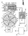
- Vane pump 2 shown schematically has a rotor 4 which is rotatably connected to a drive shaft 6.
- a rotor 4 which is rotatably connected to a drive shaft 6.
- radially outwardly extending recesses 8 are provided, in which in a known manner longitudinally displaceable rotor blades 10 are added.
- Rotor 4 and the rotor blades 10 received therein are enclosed by a cam ring 12, so that corresponding oil delivery chambers 14 are formed between rotor 4, cam ring 12 and between two adjacent rotor blades 10.
- the cam ring 12 is pivotally mounted on a housing-fixed point about an axis 16; so that its position relative to the rotor axis for adjusting a certain oil flow per revolution is variable.
- the cam ring 12 has a bearing axis 16 opposite a coupling tongue 18 which is provided with a guide pin 20 which cooperates with a gate window 22 of an actuating rod 24 in the manner of a slotted guide.
- the control rod 24 is connected to the outer circumference of a guided in a pressure control valve 26 actuating piston 28.
- a first pressure chamber 36 is formed, which is in communication with the pressure side of the vane pump 2.
- a receiving opening 38 is provided in the adjusting piston 28, in which a coil spring 40 is received or guided.
- the coil spring 40 is supported at its one end on the bottom of the piston rear side 37 and at its other end on a closure element 42 of the pressure regulating valve 26 from.
- a second pressure chamber 44 is formed, which is connected via an opening 46 provided in the closure element 42 and a hydraulic line 48 connected thereto to the inlet 50 of a control valve 52.
- the input 50 of the control valve 52 is monitored by a control piston 54, which is controlled by an opening provided on the control valve 52 electromagnet 56.
- the output 58 of the control valve 52 is connected to the oil tank or the oil reservoir 60 of the internal combustion engine, in turn, the suction side of the vane pump. 2 opens.
- the two formed in the pressure control valve 26 pressure chambers 36 and 44 are connected via a formed in the actuator piston 28 throttle, which is formed in the present embodiment as a stepped bore 62, in conjunction.
- the operation of the device for controlling the pump power of the vane pump will be explained in more detail.
- the rigidly driven by the engine of the engine vane pump promotes depending on operating parameters, based on the control diagram in Fig. 3 will be explained in more detail, a certain oil flow to the consumers of the internal combustion engine.
- the pressure chamber 36 of the pressure regulating valve 26 is connected to the pressure side of the vane pump 2.
- the position of the cam ring 12 is adjusted relative to the rotor axis of rotation and thus the oil flow per rotor revolution.
- a zero flow rate (see Fig. 2 ) are infinitely adjustable.
- the activation of the pressure control valve 26 explained in greater detail below can be used to further reduce the input drive power of the vane pump 2 as a function of operating parameters such as speed, oil temperature or load state of the internal combustion engine, thus matching the oil delivery rate and thus the oil pressure to reduce the input drive power become.
- the control piston 54 of the control valve 52 is controlled via a stored in the engine control unit characteristic field.
- a self-calibration is still provided.
- the target oil pressure is compared with the is - oil pressure. If the actual oil pressure deviates from the setpoint oil pressure by a previously defined ⁇ p, then the control curve is replaced by a Correction factor shifted until the ⁇ p corresponds to the specified criterion.
- the background to the planned self-calibration is the fact that the oil requirement of the engine changes over its service life due to bearing wear, pump wear or changing oil viscosity.
Landscapes
- Engineering & Computer Science (AREA)
- Mechanical Engineering (AREA)
- General Engineering & Computer Science (AREA)
- Details And Applications Of Rotary Liquid Pumps (AREA)
- Rotary Pumps (AREA)
- Lubrication Of Internal Combustion Engines (AREA)
- Fuel-Injection Apparatus (AREA)
Description
- Die Erfindung betrifft eine Einrichtung zur Regelung der Pumpleistung einer Schmiermittelpumpe für eine Brennkraftmaschine nach dem Oberbegriff des Patentanspruchs 1.
- Es ist allgemein bekannt, bei Verbrennungsmotoren zur Versorgung des Ölkreislaufs starr angetriebene Ölpumpen, die beispielsweise als Außen- oder Innenzahnradpumpen oder als Flügelzellenpumpen ausgebildet sind, einzusetzen. Dabei handelt es sich um Ölpumpen mit variablem oder konstantem Fördervolumen pro Pumpenradumdrehung. Sog. Konstantförderpumpen sind mit einem Druckbegrenzungsventil ausgestattet, mit deren Hilfe der maximale Öldruck eingestellt werden kann. Öffnet das Öldruckbegrenzungsventil bei einem vorab eingestellten Maximalöldruck, so wird das überschüssige Ölvolumen in den Niederdruckteil der Ölpumpe zurückgeführt.
- Da der für die Schmierung des Motors erforderliche Ölvolumenstrom nicht immer proportional zur Drehzahl des Motors bzw. zur Drehzahl der Pumpe ist, gibt es Vorschläge, den Öldruck zu regeln, um insbesondere im Teillastbereich die Antriebsleistung der Motorölpumpe reduzieren zu können. So ist beispielsweise aus der
JP - OS 9 - 885 33 - Aus der
EP 1 043 504 A2 ist eine Flügelzellenpumpe bekannt, bei der ein Hubring in einem Gehäuse schiebbar oder einseitig in einer ortsfesten Lagerstelle schwenkbar gelagert ist, wobei zur Einstellung einer bestimmten Exzentrizität der Lage des Hubringes eine schieb- und/oder drehbare Kurve vorgesehen ist, die mittels eines von einem Druckregelkreis angesteuerten Stellgliedes verlagerbar ist. - Aus der
DE 43 02 610 A1 ist eine Flügelzellenpumpe mit variablem Fördervolumen bekannt, bei der durch eine Veränderung der Lage des Hubringes zur Rotordrehachse der Volumenstrom eingestellt werden kann. Darüber hinaus wird neben der reinen Maximalöldruckbegrenzung bzw. der Fördervolumenregelung eine zusätzliche Begrenzung des Fördervolumens in Abhängigkeit von der Temperatur und/oder der Drehzahl des Motors vorgeschlagen. Dazu sind aufwendige temperaturabhängige Stellglieder sowie zusätzliche Druckregelsysteme erforderlich, die neben der Maximalöldruckbegrenzung eine Verstellung des Hubringes der Flügelzellenpumpe und damit ggf. eine Reduzierung des geförderten Ölvolumenstromes bewirken. - Es ist daher Aufgabe der Erfindung, für eine volumenstromgeregelte Flügelzellenpumpe eine Vorrichtung zu schaffen, mit der auf einfache Art und Weise ein bedarfsgerechte Schmierölversorgung der Brennkraftmaschine erfolgt, so dass die aufgenommene Leistung der Ölpumpe durch eine Absenkung des Öldrucks in bestimmten Betriebszuständen reduzierbar ist.
- Die Lösung der Aufgabe erfolgt durch die im Anspruch 1 angegebenen Merkmale.
- Mit der vorgeschlagenen Einrichtung kann auf einfache Art und Weise bei einer Flügelzellenpumpe die zur Schmierölversorgung der Brennkraftmaschine erforderliche Antriebsleistung in Abhängigkeit von Betriebsparametern der Brennkraftmaschine gesteuert werden. Damit können die für die verschiedenen Betriebszustände des Motors erforderlichen Öldrücke eingestellt bzw. angepasst werden, so dass aufgrund der reduzierten Aufnahmeleistung gegenüber einer ungeregelten Ölpumpe ein weiteres Kraftstoffeinsparpotential vorhanden ist. Die vorgeschlagene Einrichtung zur Reduzierung des Öldrucks ist auf einfache Art und Weise bei bereits in Betrieb befindlichen Flügelzellenpumpen nachrüstbar.
- Durch die in den Unteransprüchen angegebenen Merkmale sind weitere vorteilhafte Ausgestaltungen und Verbesserungen der erfindungsgemäßen Regelung der Pumpleistung einer Schmiermittelpumpe möglich.
- Die auf der Kolbenrückseite des Druckregelventils dem Motoröldruck entgegen gerichtete Kraft wird durch eine Spiralfeder erzeugt, die in einer auf der Rückseite des Kolbens vorgesehenen Aufnahmeöffnung geführt und abgestützt ist.
- Zur druckabhängigen Steuerung des Ölvolumenstroms ist in einer vom Regelventil zum Tank führenden Hydraulikleitung ein Ventilelement integriert, über das der zur Saugseite der Ölpumpe zurückführbare Ölstrom einstellbar ist.
- Der Öldruck bzw. der von der Ölpumpe geförderte Ölvolumenstrom wird in Abhängigkeit von Betriebsparametern der Brennkraftmaschine, wie Drehzahl, Last oder Motoröltemperatur gesteuert.
- Ein Ausführungsbeispiel der Erfindung ist in der Zeichnung dargestellt und wird nachfolgend näher erläutert.
- Es zeigen:
- Fig. 1
- eine schematischen Gesamtansicht einer Einrichtung zur Regelung der Pumpleistung einer Flügelzellenpumpe in einer ersten Betriebsstellung,
- Fig. 2
- die Einrichtung in einer zweiten Betriebsstellung,
- Fig. 3
- eine graphische Darstellung einer betriebspunktabhängigen Öldrucksteuerung und
- Fig. 4
- ein Blockschaltbild für eine kalibrierte Öldrucksteuerung.
- Die in
Fig. 1 und2 schematisch dargestellte Flügelzellenpumpe 2 weist einen Rotor 4 auf, der drehfest mit einer Antriebswelle 6 verbunden ist. Im Rotor 4 sind radial nach außen verlaufende Ausnehmungen 8 vorgesehen, in denen auf bekannte Art und Weise längsverschiebbare Rotorflügel 10 aufgenommen sind. Rotor 4 und die darin aufgenommenen Rotorflügel 10 sind von einem Hubring 12 umschlossen, so dass zwischen Rotor 4, Hubring 12 und zwischen zwei jeweils benachbarten Rotorflügeln 10 entsprechende Ölförderräume 14 ausgebildet sind. Der Hubring 12 ist an einem gehäusefesten Punkt um eine Achse 16 schwenkbar gelagert; damit ist seine Lage bezüglich der Rotordrehachse zur Einstellung einer bestimmten Ölfördermenge pro Umdrehung veränderbar. Dazu weist der Hubring 12 eine der Lagerachse 16 gegenüberliegende eine Anlenkzunge 18 auf, die mit einem Führungszapfen 20 versehen ist, der nach Art einer Kulissenführung mit einem Kulissenfenster 22 einer Stellstange 24 zusammenwirkt. Die Stellstange 24 ist am Außenumfang eines in einem Druckregelventil 26 geführten Stellkolbens 28 angebunden. - Zwischen dem Gehäuse 32 und der Kolben - Vorderseite 34 ist ein erster Druckraum 36 ausgebildet, der mit der Druckseite der Flügelzellenpumpe 2 in Verbindung steht. Auf der Kolbenrückseite 37 ist im Stellkolben 28 eine Aufnahmeöffnung 38 vorgesehen, in der eine Spiralfeder 40 aufgenommen bzw. geführt ist. Die Spiralfeder 40 stützt sich an ihrem einen Ende am Boden der Kolbenrückseite 37 und an ihrem anderen Ende an einem Verschlusselement 42 des Druckregelventils 26 ab. Zwischen Verschlusselement 42 und Kolbenrückseite ist ein zweiter Druckraum 44 ausgebildet, der über eine im Verschlusselement 42 vorgesehene Öffnung 46 und eine daran angeschlossene Hydraulikleitung 48 mit dem Eingang 50 eines Regelventils 52 verbunden ist. Der Eingang 50 des Regelventils 52 wird von einem Stellkolben 54 überwacht, der von einem am Regelventil 52 vorgesehenen Elektromagneten 56 gesteuert ist. Der Ausgang 58 des Regelventils 52 ist mit dem Öltank bzw. dem Ölvorratsbehälter 60 der Brennkraftmaschine verbunden, in den wiederum die Saugseite der Flügelzellenpumpe 2 einmündet. Die beiden im Druckregelventil 26 ausgebildeten Druckräume 36 und 44 stehen über eine im Stellkolben 28 ausgebildete Drossel, die im vorliegenden Ausführungsbeispiel als Stufenbohrung 62 ausgebildet ist, in Verbindung.
- Im nachfolgenden wird die Funktionsweise der Einrichtung zur Regelung der Pumpleistung der Flügelzellenpumpe näher erläutert. Die vom Motor der Brennkraftmaschine starr angetriebene Flügelzellenpumpe fördert in Abhängigkeit von Betriebsparametern, die anhand des Steuerdiagramms in
Fig. 3 noch näher erläutert werden, einen bestimmten Ölvolumenstrom zu den Verbrauchern der Brennkraftmaschine. Dabei ist der Druckraum 36 des Druckregelventils 26 mit der Druckseite der Flügelzellenpumpe 2 verbunden. In Abhängigkeit von dem im ersten Druckraum 36 herrschenden Öldruck wird die Lage des Hubringes 12 bezogen auf die Rotordrehachse und damit die Ölfördermenge pro Rotorumdrehung eingestellt. Damit kann, wie allgemein bekannt ist, der von der Flügelzellenpumpe 2 geförderte Ölvolumenstrom zwischen einer Maximalfördermenge (sieheFig. 1 ) und einer Nullfördermenge (sieheFig. 2 ) stufenlos eingestellt werden. Durch die nachfolgend näher erläuterte Ansteuerung des Druckregelventils 26 können, wie bereits eingangs erläutert, zur weiteren Reduzierung der aufgenommenen Antriebsleistung der Flügelzellenpumpe 2 in Abhängigkeit von Betriebsparametern, wie Drehzahl, Öltemperatur oder Lastzustand der Brennkraftmaschine die Ölfördermenge und damit der Öldruck zur Reduzierung der aufgenommenen Antriebsleistung angepaßt werden. Der Stellkolben 54 des Regelventils 52 wird über ein im Motorsteuergerät abgelegtes Kennlinienfeld angesteuert. Bei der inFig. 1 dargestellten Position des Stellkolbens 54 wird der Eingang 50 des Regelventils 52 vollständig verschlossen; damit ist der Druck im ersten und im zweiten Druckraum 36, 44 gleich groß, so dass der Stellkolben 28 aufgrund der Spiralfeder 40 eine Position innerhalb der Ventilbohrung 30 einnimmt, bei der die Exzentrizität der Lage des Hubringes 12 bezogen auf die Rotordrehachse der Flügelzellenpumpe 2 maximal ist. Gibt der Stellkolben 54 den Eingang 50 frei (sieheFig. 2 ), so fließt über die Stufenbohrung 62 ein bestimmter Ölvolumenstrom über die Hydraulikleitung 48 zum Ölvorratsbehälter 60 und damit zur Saugseite der Flügelzellenpumpe 2 ab. Aufgrund der Drosselwirkung der Stufenbohrung 62 wird zwischen der Vorder- und der Kolbenrückseite 34, 37 ein Differenzdruck erzeugt, so dass der Druck im zweiten Druckraum 44 gegenüber dem im ersten Druckraum 36 abgesenkt ist. Damit verändert sich die Verstellcharakteristik des Stellkolbens 28 und dieser wird, wie inFig. 2 dargestellt, entgegen der Federkraft der Spiralfeder 40 in Richtung des Verschlusselementes 42 bewegt. Damit wird über die Stellstange 24 und die Anlenkzunge 18 die Lage des Hubringes 12 bezogen auf die Rotordrehachse dergestalt verändert, dass die Ölfördermenge der Flügelzellenpumpe 2 und damit der Öldruck reduziert wird. Entsprechend dem inFig. 3 dargestellten Kennlinienfeld, welches im Motorsteuergerät abgelegt ist, können in Abhängigkeit von Öltemperatur und Drehzahl der Brennkraftmaschine beliebige Ölvolumenströme eingestellt werden, die dem entsprechenden Öldruckbedarf des Motors angepasst sind. So wird beispielsweise bei niedrigen Drehzahlen ein deutlich geringerer Öldruck für eine ausreichende Lagerversorgung benötigt, als bei hohen Drehzahlen. Extrem hohe bzw. niedrige Öltemperaturen erfordern einen höheren Öldruck, um einerseits dem höheren Kühlungsbedarf der Lager gerecht zu werden und andererseits den Leitungsdruckverlust und den Lagereintrittsdruck bei niedrigen Öltemperaturen kompensieren zu können. Darüber hinaus wird bei einem durch die Stellung der Drosselklappe signalisierten hohen Lastzustand des Motors ein höherer Öldruck als bei kleineren und mittleren Lasten benötigt. - Bei Motoren, die zur Kolbenkühlung Ölspritzdüsen verwenden, die bei einem bestimmten Schwellenöldruck öffnen, besteht nunmehr die Möglichkeit, die Kolbenspritzdüsen über das im Motorsteuergerät hinterlegte Kennfeld zu steuern. Dadurch werden zusätzlich die Reibungsverluste gesenkt und der erforderliche Förderstrom zur Motorversorgung verringert.
- Im Zusammenhang mit der vorgeschlagenen betriebspunktabhängigen Öldrucksteuerung ist weiterhin eine Selbstkalibrierung vorgesehen. Wie anhand von
Fig. 4 veranschaulicht, wird dabei der Soll - Öldruck mit dem ist - Öldruck verglichen. Weicht der Ist - Öldruck vom Soll - Öldruck um ein vorher definiertes Δp ab, so wird die Steuerkurve durch einen Korrekturfaktor so lange verschoben, bis das Δp dem vorgegebenen Kriterium entspricht. Hintergrund für die vorgesehene Selbstkalibrierung ist die Tatsache, dass sich der Ölbedarf des Motors über seine Lebensdauer aufgrund von Lagerverschleiss, Pumpenverschleiss oder sich ändernder Ölviskosität verändert.
Claims (6)
- Einrichtung zur Regelung der Pumpleistung einer als eine Flügelzellenpumpe (2) ausgebildeten Motorölpumpe für eine Brennkraftmaschine, die Flügelzellenpumpe (2) einen Rotorkörper, radial im Rotorkörper verschiebbare Rotorflügel sowie einen Hubring aufweist, dessen Lage bezüglich der Rotordrehachse zur Veränderung des Fördervolumens in Abhängigkeit von Betriebsparametern der Brennkraftmaschine einstellbar ist wobei- auf der Kolbenrückseite eines in einer Ventilbohrung (30) eines Druckegelventils (26) geführten Stellkolbens (28) ein Druckraum (44) ausgebildet ist, in dem zusätzlich ein Federelement (40) Aufnahme findet, sowie mit einer hydraulischen Leitung (48), die mit dem Druckraum (44) in Verbindung steht und über ein Regelventil (52) zur Saugseite der Flügelzellenpumpe führt, wobei- das Fördervolumen der Flügelzellenpumpe in Abhängigkeit von einem in der Drosselbohrung (62) eingestellten Ölvolumenstrom veränderbar ist;dadurch gekennzeichnet, daβ- der Hubring (12) an dem Stellkolben (28) angelenkt ist, der auf einer Kolben - Vorderseite (34) vom Motoröldruck beaufschlagt ist, und wobei- die Kolbenvorderseite (34) mit der Kolbenrückseite (37) über eine im Stellkolben angeordnete Drosselbohrung (62) in Verbindung steht.
- Einrichtung nach Anspruch 1, dadurch gekennzeichnet, dass der Stellkolben (28) auf seiner Rückseite eine Aufnahmeöffnung (38) aufweist, in der zumindest teilweise das Federelement (40) geführt und abgestützt ist, wobei dieses als eine Spiralfeder ausgebildet ist.
- Einrichtung nach Anspruch 1 oder 2, dadurch gekennzeichnet, dass über das in der hydraulischen Leitung (48) angeordnete Regelventil (52) der zur Saugseite der Flügelzellenpumpe (2) zurückführbare Ölstrom einstellbar ist.
- Einrichtung nach Anspruch 3, dadurch gekennzeichnet, dass der Ölstrom in Abhängigkeit von Betriebsparametern der Brennkraftmaschine, wie Drehzahl, Last oder Motoröltemperatur gesteuert ist.
- Einrichtung nach einem der vorhergehenden Ansprüche, dadurch gekennzeichnet, dass für eine betriebspunktabhängige Öldrucksteuerung der Flügelzellenpumpe ein Kennlinienfeld in einem Steuergerät hinterlegt ist, durch das der Öldruck in Abhängigkeit von der Drehzahl, der Motoröltemperatur oder dem Lastzustand der Brennkraftmaschine festgelegt ist.
- Einrichtung nach Anspruch 5, dadurch gekennzeichnet, dass das Kennlinienfeld durch einen Korrekturfaktor kalibrierbar ist.
Applications Claiming Priority (3)
| Application Number | Priority Date | Filing Date | Title |
|---|---|---|---|
| DE10239364A DE10239364A1 (de) | 2002-08-28 | 2002-08-28 | Einrichtung zur Regelung der Pumpleistung einer Schmiermittelpumpe für eine Brennkraftmaschine |
| DE10239364 | 2002-08-28 | ||
| PCT/EP2003/006971 WO2004020831A1 (de) | 2002-08-28 | 2003-07-01 | Einrichtung zur regelung der pumpleistung einer schmiermittelpumpe für eine brennkraftmaschine |
Publications (2)
| Publication Number | Publication Date |
|---|---|
| EP1537335A1 EP1537335A1 (de) | 2005-06-08 |
| EP1537335B1 true EP1537335B1 (de) | 2008-09-24 |
Family
ID=31724118
Family Applications (1)
| Application Number | Title | Priority Date | Filing Date |
|---|---|---|---|
| EP03740393A Expired - Lifetime EP1537335B1 (de) | 2002-08-28 | 2003-07-01 | Einrichtung zur regelung der pumpleistung einer schmiermittelpumpe für eine brennkraftmaschine |
Country Status (6)
| Country | Link |
|---|---|
| US (1) | US7549848B2 (de) |
| EP (1) | EP1537335B1 (de) |
| JP (1) | JP2005520096A (de) |
| AT (1) | ATE409285T1 (de) |
| DE (2) | DE10239364A1 (de) |
| WO (1) | WO2004020831A1 (de) |
Families Citing this family (36)
| Publication number | Priority date | Publication date | Assignee | Title |
|---|---|---|---|---|
| EP2740937A1 (de) * | 2004-09-20 | 2014-06-11 | Magna Powertrain Inc. | Pumpe mit wählbarem Auslassdruck |
| DE102004049029B4 (de) * | 2004-10-08 | 2015-05-21 | Audi Ag | Vorrichtung und Verfahren zur Regelung eines Schmieröldrucks eines Verbrennungsmotors |
| EP3165769B1 (de) * | 2004-12-22 | 2018-12-12 | Magna Powertrain Inc. | Verfahren zum betrieb einer pumpe mit variabler kapazität |
| US9181803B2 (en) | 2004-12-22 | 2015-11-10 | Magna Powertrain Inc. | Vane pump with multiple control chambers |
| DE102005006703A1 (de) * | 2005-02-15 | 2006-08-17 | Audi Ag | Vorrichtung und Verfahren zur Schmierölversorgung |
| ITBO20050383A1 (it) * | 2005-06-01 | 2006-12-02 | Pierburg Spa | Sistema di controllo per pompe olio |
| DE102005038204A1 (de) * | 2005-08-12 | 2007-02-15 | Dr.Ing.H.C. F. Porsche Ag | Einrichtung zur Steuerung der Schmierölversorgung für Antriebsaggregate |
| EP1945920B1 (de) * | 2005-10-14 | 2009-12-30 | Renault Trucks | Schmiersystem und solch ein system umfassender verbrennungsmotor |
| CA2637454C (en) * | 2006-01-31 | 2014-12-23 | Magna Powertrain Inc. | Variable displacement variable pressure vane pump system |
| US7823545B2 (en) * | 2007-08-17 | 2010-11-02 | Gm Global Technology Operations, Inc. | Piston squirter system and method |
| CN101614204B (zh) * | 2008-06-27 | 2011-07-20 | 托克海姆控股有限公司 | 带叶片的液体传送装置 |
| DE102008048856A1 (de) * | 2008-09-25 | 2010-04-08 | Bayerische Motoren Werke Aktiengesellschaft | Druckregeleinheit |
| JP5174720B2 (ja) | 2009-03-09 | 2013-04-03 | 日立オートモティブシステムズ株式会社 | 可変容量形ポンプ |
| WO2010147979A1 (en) * | 2009-06-17 | 2010-12-23 | Green Partners Technology Holding Gmbh | Rotary vane engines and methods |
| GB2471514B (en) * | 2009-07-03 | 2013-08-14 | Ford Global Tech Llc | Heat exchanging systems for motor vehicles |
| DE102010019007A1 (de) * | 2010-05-03 | 2011-11-03 | Gm Global Technology Operations Llc (N.D.Ges.D. Staates Delaware) | Schmierstoffkreislauf |
| FR2972487A1 (fr) * | 2011-03-07 | 2012-09-14 | Peugeot Citroen Automobiles Sa | Systeme de lubrification d'un moteur thermique, comprenant une pompe a huile a cylindree variable |
| FR2972488B1 (fr) | 2011-03-10 | 2013-03-29 | Peugeot Citroen Automobiles Sa | Systeme de lubrification d'un moteur thermique, comprenant une pompe a huile a cylindree variable |
| US9121335B2 (en) | 2011-05-13 | 2015-09-01 | Ford Global Technologies, Llc | System and method for an engine comprising a liquid cooling system and oil supply |
| KR101251387B1 (ko) * | 2012-01-09 | 2013-04-09 | 정기영 | 펌프의 토출구 압력 제어장치 |
| DE102012200279A1 (de) * | 2012-01-11 | 2013-07-11 | Ford Global Technologies, Llc | Verfahren und Vorrichtung zum Betreiben eines Schmiersystems einesVerbrennungsmotors |
| KR20130109323A (ko) * | 2012-03-27 | 2013-10-08 | 현대자동차주식회사 | 차량용 오일펌프 제어시스템 및 이의 운용방법 |
| DE102012217050A1 (de) | 2012-09-21 | 2014-03-27 | Robert Bosch Gmbh | Pumpenanordnung umfassend eine Flügelzellenpumpe |
| DE102012217100A1 (de) | 2012-09-24 | 2014-04-17 | Robert Bosch Gmbh | Pumpenanordnung umfassend eine Flügelzellenpumpe |
| KR101326850B1 (ko) | 2012-10-04 | 2013-11-11 | 기아자동차주식회사 | 오일펌프 제어 시스템 및 방법 |
| KR20140045183A (ko) * | 2012-10-08 | 2014-04-16 | 현대자동차주식회사 | 차량용 자동변속기의 유압공급시스템 |
| US9109597B2 (en) | 2013-01-15 | 2015-08-18 | Stackpole International Engineered Products Ltd | Variable displacement pump with multiple pressure chambers where a circumferential extent of a first portion of a first chamber is greater than a second portion |
| CN103225614A (zh) * | 2013-04-10 | 2013-07-31 | 上海真空泵厂有限公司 | 排气缓冲部件结构 |
| CN103511235A (zh) * | 2013-10-18 | 2014-01-15 | 无锡威孚精密机械制造有限责任公司 | 用于液压柱塞泵的低噪声抽油机构 |
| EP3071836B1 (de) * | 2013-11-21 | 2019-01-09 | Pierburg Pump Technology GmbH | Schmiermittelverstellpumpe |
| US9874209B2 (en) * | 2014-02-11 | 2018-01-23 | Magna Powertrain Bad Homburg GmbH | Variable displacement transmission pump and controller with adaptive control |
| JP6154357B2 (ja) * | 2014-06-27 | 2017-06-28 | トヨタ自動車株式会社 | オイルポンプの制御装置 |
| JP6776962B2 (ja) * | 2017-03-16 | 2020-10-28 | トヨタ自動車株式会社 | 車載エンジンのオイル供給装置 |
| KR20210081884A (ko) * | 2019-12-24 | 2021-07-02 | 조봉현 | 가변 베인 오일 펌프 |
| CN116378797B (zh) * | 2023-03-15 | 2025-07-18 | 潍柴动力股份有限公司 | 一种机油压力控制系统及发动机 |
| DE102023134124A1 (de) * | 2023-12-06 | 2025-06-12 | Pump Technology Solutions PS GmbH | Verstellbare, einhubige Flügelzellenpumpe, Verfahren zum Betreiben einer Flügelzellenpumpe, System zur Erzeugung eines Druckmittelstroms und Lenksystem |
Family Cites Families (11)
| Publication number | Priority date | Publication date | Assignee | Title |
|---|---|---|---|---|
| US2606503A (en) * | 1946-01-11 | 1952-08-12 | Worthington Corp | Variable capacity rotary pump |
| US2639585A (en) * | 1951-12-15 | 1953-05-26 | Florence Pipe Foundry And Mach | Hydraulic press cycle control system |
| FR2195271A1 (de) * | 1972-08-04 | 1974-03-01 | Peugeot & Renault | |
| DE3429935C2 (de) * | 1984-08-14 | 1987-02-12 | Mannesmann Rexroth GmbH, 8770 Lohr | Direktbetätigte Flügelzellenpumpe |
| DE4038549C1 (en) * | 1990-12-04 | 1992-01-09 | Mercedes-Benz Aktiengesellschaft, 7000 Stuttgart, De | IC engine oil pressure regulator - has piston control chamber connected to oil circuit pump assembly |
| DE4302610C2 (de) * | 1993-01-30 | 1996-08-08 | Daimler Benz Ag | Verfahren zum Regeln der Pumpleistung von Schmiermittelpumpen und Schmiermittelpumpe hierfür |
| DE4428410C2 (de) * | 1994-08-11 | 1998-05-28 | Daimler Benz Ag | Kompakte Regeleinheit für eine Flügelzellenpumpe |
| JP3122348B2 (ja) * | 1995-09-26 | 2001-01-09 | 東京部品工業株式会社 | エンジン潤滑油供給装置 |
| DE19915739A1 (de) | 1999-04-08 | 2000-10-12 | Bayerische Motoren Werke Ag | Mengenregelbare Flügelzellenpumpe |
| US6623250B2 (en) * | 2000-02-17 | 2003-09-23 | Goodrich Pump And Engine Control Systems, Inc. | Fuel metering unit |
| US6790013B2 (en) * | 2000-12-12 | 2004-09-14 | Borgwarner Inc. | Variable displacement vane pump with variable target regulator |
-
2002
- 2002-08-28 DE DE10239364A patent/DE10239364A1/de not_active Ceased
-
2003
- 2003-07-01 US US10/512,889 patent/US7549848B2/en not_active Expired - Fee Related
- 2003-07-01 EP EP03740393A patent/EP1537335B1/de not_active Expired - Lifetime
- 2003-07-01 JP JP2004531781A patent/JP2005520096A/ja active Pending
- 2003-07-01 AT AT03740393T patent/ATE409285T1/de not_active IP Right Cessation
- 2003-07-01 WO PCT/EP2003/006971 patent/WO2004020831A1/de not_active Ceased
- 2003-07-01 DE DE50310547T patent/DE50310547D1/de not_active Expired - Lifetime
Also Published As
| Publication number | Publication date |
|---|---|
| EP1537335A1 (de) | 2005-06-08 |
| WO2004020831A1 (de) | 2004-03-11 |
| DE10239364A1 (de) | 2004-03-18 |
| JP2005520096A (ja) | 2005-07-07 |
| US20050232785A1 (en) | 2005-10-20 |
| ATE409285T1 (de) | 2008-10-15 |
| US7549848B2 (en) | 2009-06-23 |
| DE50310547D1 (de) | 2008-11-06 |
Similar Documents
| Publication | Publication Date | Title |
|---|---|---|
| EP1537335B1 (de) | Einrichtung zur regelung der pumpleistung einer schmiermittelpumpe für eine brennkraftmaschine | |
| DE3333647C2 (de) | Schmiermittelpumpe für die Druckerzeugung bei einem druckumlaufgeschmierten Verbrennungsmotor | |
| DE102004003335B4 (de) | Motorölsystem mit Verstellpumpe | |
| EP1485621B1 (de) | System zur steuerung einer hydraulischen verstellpumpe | |
| EP2440785B1 (de) | Schmierstoffpumpensystem | |
| EP2307726B1 (de) | Verstellpumpe mit einem mengenregler und einem druckventil. | |
| DE102005051098B4 (de) | Gerotorpumpe mit veränderlicher Förderleistung | |
| DE10141786B4 (de) | Einrichtung zur Regelung des Schmieröldruckes einer Brennkraftmaschine | |
| DE10039347A1 (de) | Hydraulikpumpe mit variabler Fördermenge | |
| DE10223466B4 (de) | Pumpe | |
| DE112016003646T5 (de) | Ölregelpumpe | |
| EP1911964B1 (de) | Kraftstoffhochdruckpumpe und Kraftstoffeinspritzsystem für eine Brennkraftmaschine | |
| EP1853824B1 (de) | Vorrichtung und verfahren zur schmierölversorgung | |
| EP0642430B1 (de) | Von einem verbrennungsmotor angetriebene hydraulikpumpe | |
| DE102007004187B4 (de) | Regelbare Kühlmittelpumpe | |
| EP0533720B1 (de) | Antriebsvorrichtung | |
| EP2406498B1 (de) | Regelbare kühlmittelpumpe | |
| DE102009023824A1 (de) | Thermostat-Druckbegrenzungsventil, selbstregelnde Fluidpumpe und Schmierölkreislauf einer Brennkraftmaschine | |
| DE10231197B4 (de) | Schmiermittelpumpanlage | |
| EP1394403B1 (de) | Kraftstoffsystem für eine Brennkraftmaschine | |
| DE19827970A1 (de) | Regeleinrichtung für Hydraulikpumpen | |
| DE10138187B4 (de) | Mengenregelbare Flügelzellenpumpe | |
| DE102009060189A1 (de) | Regelvorrichtung für die Verstellung des Fördervolumens einer Pumpe | |
| EP1911974A1 (de) | Druckregelung für Aussenzahnrad-Regelölpumpen | |
| DE4134184A1 (de) | Verstellbare hydrostatische pumpe |
Legal Events
| Date | Code | Title | Description |
|---|---|---|---|
| PUAI | Public reference made under article 153(3) epc to a published international application that has entered the european phase |
Free format text: ORIGINAL CODE: 0009012 |
|
| 17P | Request for examination filed |
Effective date: 20050329 |
|
| AK | Designated contracting states |
Kind code of ref document: A1 Designated state(s): AT BE BG CH CY CZ DE DK EE ES FI FR GB GR HU IE IT LI LU MC NL PT RO SE SI SK TR |
|
| AX | Request for extension of the european patent |
Extension state: AL LT LV MK |
|
| DAX | Request for extension of the european patent (deleted) | ||
| RBV | Designated contracting states (corrected) |
Designated state(s): AT DE FR GB IT |
|
| RIN1 | Information on inventor provided before grant (corrected) |
Inventor name: SCHOLL, PETER |
|
| RIN1 | Information on inventor provided before grant (corrected) |
Inventor name: SCHOLL, PETER |
|
| GRAP | Despatch of communication of intention to grant a patent |
Free format text: ORIGINAL CODE: EPIDOSNIGR1 |
|
| RAP1 | Party data changed (applicant data changed or rights of an application transferred) |
Owner name: DR. ING. H.C. F. PORSCHE AKTIENGESELLSCHAFT |
|
| RIC1 | Information provided on ipc code assigned before grant |
Ipc: F04C 14/22 20060101AFI20080414BHEP Ipc: F04C 2/344 20060101ALI20080414BHEP |
|
| GRAS | Grant fee paid |
Free format text: ORIGINAL CODE: EPIDOSNIGR3 |
|
| RAP1 | Party data changed (applicant data changed or rights of an application transferred) |
Owner name: DR. ING. H.C. F. PORSCHE AKTIENGESELLSCHAFT |
|
| GRAA | (expected) grant |
Free format text: ORIGINAL CODE: 0009210 |
|
| AK | Designated contracting states |
Kind code of ref document: B1 Designated state(s): AT DE FR GB IT |
|
| REG | Reference to a national code |
Ref country code: GB Ref legal event code: FG4D Free format text: NOT ENGLISH |
|
| REF | Corresponds to: |
Ref document number: 50310547 Country of ref document: DE Date of ref document: 20081106 Kind code of ref document: P |
|
| PLBE | No opposition filed within time limit |
Free format text: ORIGINAL CODE: 0009261 |
|
| STAA | Information on the status of an ep patent application or granted ep patent |
Free format text: STATUS: NO OPPOSITION FILED WITHIN TIME LIMIT |
|
| PG25 | Lapsed in a contracting state [announced via postgrant information from national office to epo] |
Ref country code: IT Free format text: LAPSE BECAUSE OF FAILURE TO SUBMIT A TRANSLATION OF THE DESCRIPTION OR TO PAY THE FEE WITHIN THE PRESCRIBED TIME-LIMIT Effective date: 20080924 |
|
| 26N | No opposition filed |
Effective date: 20090625 |
|
| PG25 | Lapsed in a contracting state [announced via postgrant information from national office to epo] |
Ref country code: AT Free format text: LAPSE BECAUSE OF NON-PAYMENT OF DUE FEES Effective date: 20090701 |
|
| REG | Reference to a national code |
Ref country code: FR Ref legal event code: TP |
|
| REG | Reference to a national code |
Ref country code: GB Ref legal event code: 732E Free format text: REGISTERED BETWEEN 20110310 AND 20110316 |
|
| REG | Reference to a national code |
Ref country code: GB Ref legal event code: 732E Free format text: REGISTERED BETWEEN 20110331 AND 20110406 |
|
| PGFP | Annual fee paid to national office [announced via postgrant information from national office to epo] |
Ref country code: FR Payment date: 20110729 Year of fee payment: 9 |
|
| PGFP | Annual fee paid to national office [announced via postgrant information from national office to epo] |
Ref country code: GB Payment date: 20110721 Year of fee payment: 9 |
|
| GBPC | Gb: european patent ceased through non-payment of renewal fee |
Effective date: 20120701 |
|
| REG | Reference to a national code |
Ref country code: FR Ref legal event code: ST Effective date: 20130329 |
|
| PG25 | Lapsed in a contracting state [announced via postgrant information from national office to epo] |
Ref country code: FR Free format text: LAPSE BECAUSE OF NON-PAYMENT OF DUE FEES Effective date: 20120731 Ref country code: GB Free format text: LAPSE BECAUSE OF NON-PAYMENT OF DUE FEES Effective date: 20120701 |
|
| PGFP | Annual fee paid to national office [announced via postgrant information from national office to epo] |
Ref country code: DE Payment date: 20180703 Year of fee payment: 16 |
|
| REG | Reference to a national code |
Ref country code: DE Ref legal event code: R119 Ref document number: 50310547 Country of ref document: DE |
|
| PG25 | Lapsed in a contracting state [announced via postgrant information from national office to epo] |
Ref country code: DE Free format text: LAPSE BECAUSE OF NON-PAYMENT OF DUE FEES Effective date: 20200201 |