EP1536237A2 - Automatische Analysevorrichtung - Google Patents
Automatische Analysevorrichtung Download PDFInfo
- Publication number
- EP1536237A2 EP1536237A2 EP04027525A EP04027525A EP1536237A2 EP 1536237 A2 EP1536237 A2 EP 1536237A2 EP 04027525 A EP04027525 A EP 04027525A EP 04027525 A EP04027525 A EP 04027525A EP 1536237 A2 EP1536237 A2 EP 1536237A2
- Authority
- EP
- European Patent Office
- Prior art keywords
- reaction
- sample
- dispensing
- reaction disk
- automatic analyzer
- Prior art date
- Legal status (The legal status is an assumption and is not a legal conclusion. Google has not performed a legal analysis and makes no representation as to the accuracy of the status listed.)
- Withdrawn
Links
Images


Classifications
-
- G—PHYSICS
- G01—MEASURING; TESTING
- G01N—INVESTIGATING OR ANALYSING MATERIALS BY DETERMINING THEIR CHEMICAL OR PHYSICAL PROPERTIES
- G01N35/00—Automatic analysis not limited to methods or materials provided for in any single one of groups G01N1/00 - G01N33/00; Handling materials therefor
- G01N35/02—Automatic analysis not limited to methods or materials provided for in any single one of groups G01N1/00 - G01N33/00; Handling materials therefor using a plurality of sample containers moved by a conveyor system past one or more treatment or analysis stations
- G01N35/025—Automatic analysis not limited to methods or materials provided for in any single one of groups G01N1/00 - G01N33/00; Handling materials therefor using a plurality of sample containers moved by a conveyor system past one or more treatment or analysis stations having a carousel or turntable for reaction cells or cuvettes
-
- G—PHYSICS
- G01—MEASURING; TESTING
- G01N—INVESTIGATING OR ANALYSING MATERIALS BY DETERMINING THEIR CHEMICAL OR PHYSICAL PROPERTIES
- G01N35/00—Automatic analysis not limited to methods or materials provided for in any single one of groups G01N1/00 - G01N33/00; Handling materials therefor
- G01N35/00584—Control arrangements for automatic analysers
- G01N35/00594—Quality control, including calibration or testing of components of the analyser
- G01N35/00603—Reinspection of samples
-
- G—PHYSICS
- G01—MEASURING; TESTING
- G01N—INVESTIGATING OR ANALYSING MATERIALS BY DETERMINING THEIR CHEMICAL OR PHYSICAL PROPERTIES
- G01N35/00—Automatic analysis not limited to methods or materials provided for in any single one of groups G01N1/00 - G01N33/00; Handling materials therefor
- G01N35/00584—Control arrangements for automatic analysers
- G01N35/0092—Scheduling
-
- G—PHYSICS
- G01—MEASURING; TESTING
- G01N—INVESTIGATING OR ANALYSING MATERIALS BY DETERMINING THEIR CHEMICAL OR PHYSICAL PROPERTIES
- G01N35/00—Automatic analysis not limited to methods or materials provided for in any single one of groups G01N1/00 - G01N33/00; Handling materials therefor
- G01N35/10—Devices for transferring samples or any liquids to, in, or from, the analysis apparatus, e.g. suction devices, injection devices
- G01N35/1009—Characterised by arrangements for controlling the aspiration or dispense of liquids
- G01N35/1011—Control of the position or alignment of the transfer device
-
- G—PHYSICS
- G01—MEASURING; TESTING
- G01N—INVESTIGATING OR ANALYSING MATERIALS BY DETERMINING THEIR CHEMICAL OR PHYSICAL PROPERTIES
- G01N35/00—Automatic analysis not limited to methods or materials provided for in any single one of groups G01N1/00 - G01N33/00; Handling materials therefor
- G01N35/00584—Control arrangements for automatic analysers
- G01N35/0092—Scheduling
- G01N2035/0093—Scheduling random access not determined by physical position
Definitions
- the present invention relates to an automatic analyzer for performing quantitative or qualitative analysis of components of biological samples, such as blood or urine, and more particularly to an automatic analyzer with a sample diluting function.
- Patent Reference 1 JP,A 2000-146987 discloses a method of stocking a part of a sample in another reaction cell beforehand.
- Patent Reference 2 JP,B 4-7956.
- Patent Reference 1 is effective only in the case of re-measurement and is not adaptable for reducing the sample amount.
- Patent Reference 2 is effective only in the case of reducing the sample amount with pre-dilution of the sample and is not easily adaptable for re-measurement.
- a sampling probe is employed to add a diluent and to suck the diluted sample for ejection into another empty reaction cell.
- the sampling probe is installed near an outer periphery of the reaction disk and is able to access reaction cells only in particular positions on the reaction disk (for sucking and ejecting samples).
- the reaction disk must be rotated such that a sample to be measured again comes to the position accessible by the sampling probe.
- the reaction disk cannot be rotated for only the sample to be measured again. It has been hence difficult to take a quick action for the re-measurement.
- an object of the present invention is to provide an automatic analyzer which can quickly release a sample for transfer to another unit and can simply measure the sample again without using a bulky and intricate mechanism for transferring a sample-cup holding rack to perform automatic re-measurement.
- the present invention is constituted as follows.
- an automatic analyzer of the present invention comprises a reaction disk holding a plurality of reaction cells arranged in a row along the circumference of the reaction disk; and a sample dispensing mechanism for dispensing samples into the reaction cells on the reaction disk, wherein the sample dispensing mechanism comprises a dispensing nozzle for dispensing the samples, and a support mechanism for supporting the dispensing nozzle, and the support mechanism is disposed inside the circumference of the reaction disk along which the reaction cells are arranged in a row.
- the automatic analyzer of the present invention further comprises a reagent dispensing mechanism for dispensing reagents into the reaction cells on the reaction disk, and an analyzing mechanism for analyzing reactions occurred in the reaction cells on the reaction disk.
- a part of the sample in an undiluted state is dispensed into another reaction cell for the re-measurement beforehand at the end of operation for dispensing that sample.
- a part of the sample may be stocked in a diluted state by dispensing the sample into another reaction cell and adding a diluent to the other reaction cell by the reagent dispensing mechanism.
- a part of the sample may be stocked in both the undiluted state and the diluted state. In this case, two reaction cells are used to stock the sample.
- a mechanism for moving the dispensing nozzle is constructed to be able to suck the sample in the reaction cell at any of positions where the reaction cells are stopped. For example, when primary analysis is completed and analysis results show the necessity of re-measurement, the re-measurement is performed through the steps of dispensing the sample again from the reaction cell, in which the sample has been stocked beforehand as mentioned above, into another reaction cell, adding a reagent to the dispensed sample in the other reaction cell, stirring a mixture, and measuring the absorbance of the sample.
- the re-measurement can be started as soon as an alarm is issued.
- the sample can be dispensed many times from one reaction cell that stocks the diluted sample. Therefore, the diluted sample can be dispensed for various analysis items in primary analysis, and a relative reduction in sample amount can be realized.
- a reaction cell usually employed for analysis is employed for stocking an undiluted or diluted sample.
- a sample is separately dispensed in at least one reaction cell as it is or after being diluted.
- a sampling probe is arranged to be movable along such a locus as enabling the probe to suck the sample from any of plural positions where the reaction cell containing the separately dispensed undiluted or diluted sample is stopped. Therefore, re-measurement can be performed at any time, as the occasion requires, by sucking the undiluted or diluted sample with the sampling probe to be dispensed into a new reaction cell, and adding a reagent to the dispensed sample.
- the number of reaction cells required for stocking the sample is just one or two, and hence unnecessary use of the reaction cells can be avoided.
- the result of primary analysis is obtained before the measurement reaches a maximum reaction time (about 10 minutes). Also, for some samples, a reaction abruptly progresses because of an excessively high sample concentration in a certain analysis item, and an alarm indicating the necessity of re-measurement is issued in a short time (about 1 minute). However, since the sampling probe is able to suck the sample from any position, i.e., regardless of where the reaction cell stocking the relevant sample is positioned, the re-measurement can be started as soon as the alarm is issued.
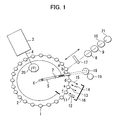
- a sampling-probe moving mechanism has a sampling arm 5, and a rotation center position 6 of the arm 5 is located exactly at or near the center of the reaction disk 2.
- the arm rotation center position 6 is also radially movable to a shift position 7.
- a sampling probe (not shown) is driven with three-axis driving, i.e., a vertical movement of the probe, an arm rotation, and a horizontal shift of the arm rotation center. Therefore, the sampling probe is able to suck and dispense the reaction liquid from any position where the reaction cell is stopped.
- the arm rotation center position 6 is shifted to the shift position 7 with the sampling probe mounted to a fore end of the sampling arm 5, and the sampling probe is moved downward and inserted in a sample cup 18 in which the sample (1) is contained.
- the sampling probe is moved upward and the arm rotation center position 6 is returned to the original position, followed by dispensing the sucked sample into a reaction cell (a).
- the reaction disk 2 is rotated through one turn and the angular distance corresponding to one reaction cell, and then stopped.
- a reagent dispensing mechanism 17 sucks a reagent for the analysis item A from a reagent bottle 8 and adds the sucked reagent into the reaction cell (a).
- the sample dispensed into the reaction cell (d) serves as a stocked sample for re-measurement, which is prepared in advance in anticipation of the case that the re-measurement is required based on the analysis result.
- a sample (2) is dispensed into a reaction cell (e) from a sample cup 19.
- the reagent dispensing mechanism 17 sucks 80 ⁇ l of a diluent from a diluent bottle 21 and adds the sucked diluent into the reaction cell (e). This means that 100 ⁇ l of the 5-time diluted sample (2) is present in the reaction cell (e). Further, 5 ⁇ l of the sample (2) in an undiluted state and the reagent A are mixed in a reaction cell (f). A reaction process in the reaction cell (f) is then measured.
- the sampling probe is inserted in the reaction cell (e) to suck 4 ⁇ l of the diluted sample (2), and dispenses the sucked sample into a reaction cell (g).
- This operation can be performed by setting the arm rotation center position 6 to the original position, and rotating the arm 5. Transferring (re-dispensing) 4 ⁇ l of the 5-time diluted sample (2) in the reaction cell (e) into the reaction cell (g) is equivalent to that 0.8 ⁇ l of the sample (2) in an undiluted state is dispensed into the reaction cell (g). That process is adapted for reducing the amount of the dispensed sample.
- dispensing of the diluted sample can be continued to perform various analysis items in the primary analysis, and the remaining diluted sample can be used for re-measurement.
- reaction cell for which the reaction time has lapsed is sent to a reaction-cell washing mechanism 16 where the reaction cell is washed by repeating the steps of pouring and sucking water for washing while sucking nozzles 11, 13 and 15 and washing nozzles 12, 14 are alternately inserted into the reaction cell.
- the reaction cell having finished the washing is used again for new analysis. Because the reaction-cell washing nozzles and the sampling probe are arranged such that they possibly physically collide with each other, a region in which the sampling arm is rotatable is restricted so as to avoid the collision between them.
- Collision between the reagent dispensing mechanism 17 and the sampling probe can be avoided by shifting the timings from each other at which they come to a position above the relevant reaction cell.
- That operation can be realized because the sampling probe is movable above a row of the reaction cells arranged along the circumference with a turn of the sampling arm and is able to suck the sample stocked in the reaction cell at any of all the positions except for those indicated by (d), (e) and (f) where the reaction-cell washing nozzles are arranged.
- the rotation center position 6 of the sampling arm 5 is located, by way of example, exactly at or near the center of the reaction disk 2.
- a driving mechanism for moving the sampling probe may operate with three-axis driving in XYZ directions such that a sample can be sucked and dispensed from a desired reaction cell at any position.
- a sample dispensing mechanism capable of freely moving a dispensing nozzle in the XYZ directions may be used instead of the swing-type sampling arm.
- the mechanism may be designed to extend or contract only the arm instead of moving the arm rotation center position.
- FIG. 3 shows a known automatic analyzer to which the present invention is applied, and in which the support mechanism for the sample dispensing nozzle is installed outside the reaction disk.
- the construction of the automatic analyzer shown in Fig. 3 is basically the same as that in the present invention except that the support mechanism for the sample dispensing nozzle is installed outside the reaction disk.
- the automatic analyzer comprises primarily three mechanisms, i.e., a sample disk 32, a reaction disk 31, and a reagent disk 33.
- FIG. 3 Layout of the various mechanisms in operation near the reaction disk 31 is shown in Fig. 3.
- a lamp serving as a light source for measuring the absorbance of a sample is disposed inside the reaction disk, and a photometer unit 37 is installed outside the reaction disk.
- a reaction cell 42 on the reaction disk passes an optical axis between the light source and the photometer, the absorbance of the sample in the reaction cell is measured.
- the measurement of the absorbance is started after the reaction disk has started rotation and has been accelerated until reaching a certain speed.
- the reaction disk repeats a rotation over a certain angular distance and a stop in each cycle, while the measurement is performed repeatedly after the lapse of each predetermined reaction time.
- the above-mentioned mechanisms are controlled primarily by a computer unit, i.e., a control unit 41.
- An operating computer 45 for handling sample information and reagent management information and accepting analysis requests is connected to the control unit 41 for coordinated operation.
Landscapes
- Chemical & Material Sciences (AREA)
- Biochemistry (AREA)
- Physics & Mathematics (AREA)
- Health & Medical Sciences (AREA)
- Life Sciences & Earth Sciences (AREA)
- Analytical Chemistry (AREA)
- General Health & Medical Sciences (AREA)
- General Physics & Mathematics (AREA)
- Immunology (AREA)
- Pathology (AREA)
- Engineering & Computer Science (AREA)
- Quality & Reliability (AREA)
- Chemical Kinetics & Catalysis (AREA)
- Automatic Analysis And Handling Materials Therefor (AREA)
Applications Claiming Priority (2)
| Application Number | Priority Date | Filing Date | Title |
|---|---|---|---|
| JP2003393231A JP4102739B2 (ja) | 2003-11-25 | 2003-11-25 | 自動分析装置 |
| JP2003393231 | 2003-11-25 |
Publications (2)
| Publication Number | Publication Date |
|---|---|
| EP1536237A2 true EP1536237A2 (de) | 2005-06-01 |
| EP1536237A3 EP1536237A3 (de) | 2005-09-14 |
Family
ID=34463768
Family Applications (1)
| Application Number | Title | Priority Date | Filing Date |
|---|---|---|---|
| EP04027525A Withdrawn EP1536237A3 (de) | 2003-11-25 | 2004-11-19 | Automatische Analysevorrichtung |
Country Status (4)
| Country | Link |
|---|---|
| US (1) | US20050112025A1 (de) |
| EP (1) | EP1536237A3 (de) |
| JP (1) | JP4102739B2 (de) |
| CN (1) | CN1621846A (de) |
Families Citing this family (24)
| Publication number | Priority date | Publication date | Assignee | Title |
|---|---|---|---|---|
| US7910531B2 (en) * | 2004-06-17 | 2011-03-22 | C2C Technologies Llc | Composition and method for producing colored bubbles |
| US20060222675A1 (en) * | 2005-03-29 | 2006-10-05 | Sabnis Ram W | Personal care compositions with color changing indicator |
| US20060236470A1 (en) * | 2005-03-29 | 2006-10-26 | Sabnis Ram W | Novelty compositions with color changing indicator |
| US20060257439A1 (en) * | 2005-03-29 | 2006-11-16 | Sabnis Ram W | Cleansing compositions with color changing indicator |
| US20060222601A1 (en) * | 2005-03-29 | 2006-10-05 | Sabnis Ram W | Oral care compositions with color changing indicator |
| US20070010400A1 (en) * | 2005-07-06 | 2007-01-11 | Sabnis Ram W | Use of color changing indicators in consumer products |
| CN1329734C (zh) * | 2005-09-07 | 2007-08-01 | 杭州电子科技大学 | 一种微量试剂加给检测装置 |
| JP2007212200A (ja) * | 2006-02-08 | 2007-08-23 | Hitachi High-Technologies Corp | 自動分析装置 |
| EP2211168A4 (de) * | 2007-10-30 | 2014-04-02 | Arkray Inc | Verfahren zur probenanalyse und zugehöriges gerät |
| JP5431755B2 (ja) * | 2008-10-31 | 2014-03-05 | シスメックス株式会社 | 検体分析装置および検体分析方法 |
| JP5726993B2 (ja) * | 2008-10-31 | 2015-06-03 | シスメックス株式会社 | 検体分析装置および検体分析方法 |
| JP5300447B2 (ja) | 2008-12-04 | 2013-09-25 | ベックマン コールター, インコーポレイテッド | 自動分析装置および自動分析装置における検体分注方法 |
| JP2010249755A (ja) * | 2009-04-20 | 2010-11-04 | Hitachi High-Technologies Corp | 自動分析装置 |
| US9176037B2 (en) * | 2009-08-10 | 2015-11-03 | Hitachi High-Technologies Corporation | Specimen processing system |
| JP5372723B2 (ja) * | 2009-12-15 | 2013-12-18 | 株式会社日立ハイテクノロジーズ | 自動分析装置 |
| CN103769022B (zh) * | 2014-01-16 | 2015-10-14 | 东软安德医疗科技有限公司 | 一种自动生化分析装置及其反应杯组 |
| JP2019066254A (ja) * | 2017-09-29 | 2019-04-25 | 株式会社安川電機 | 分注システム及び分注方法 |
| JP6914887B2 (ja) * | 2018-05-16 | 2021-08-04 | 日本電子株式会社 | 自動分析装置、および自動分析方法 |
| JP6843800B2 (ja) * | 2018-06-19 | 2021-03-17 | 日本電子株式会社 | 自動分析装置、および自動分析方法 |
| CN113219185B (zh) * | 2020-01-21 | 2023-08-08 | 深圳迎凯生物科技有限公司 | 稀释方法及稀释装置 |
| WO2022018856A1 (ja) * | 2020-07-22 | 2022-01-27 | 株式会社島津製作所 | 自動試料注入システム及びガスクロマトグラフィ分析システム |
| CN115541905A (zh) * | 2021-06-30 | 2022-12-30 | 深圳市瑞图生物技术有限公司 | 一种样本分析仪及样本分析仪的检测方法 |
| JP7688149B2 (ja) * | 2021-10-25 | 2025-06-03 | 株式会社日立ハイテク | 自動分析装置の制御方法、自動分析装置 |
| CN119438609B (zh) * | 2024-11-08 | 2025-11-07 | 深圳普门科技股份有限公司 | 样本处理与调度系统及控制方法 |
Citations (1)
| Publication number | Priority date | Publication date | Assignee | Title |
|---|---|---|---|---|
| US6409968B1 (en) * | 1998-11-05 | 2002-06-25 | Hitachi, Ltd. | Automatic analysis apparatus for biological fluid sample and automatic analysis method therefor |
Family Cites Families (12)
| Publication number | Priority date | Publication date | Assignee | Title |
|---|---|---|---|---|
| US3192968A (en) * | 1962-07-02 | 1965-07-06 | Warner Lambert Pharmaceutical | Apparatus for performing analytical procedures |
| US3594129A (en) * | 1969-09-03 | 1971-07-20 | American Hospital Supply Corp | Single-channel analyzer |
| US3788816A (en) * | 1972-03-02 | 1974-01-29 | Beckman Instruments Inc | Chemical analysis rotary module |
| HU168257B (de) * | 1973-05-18 | 1976-03-28 | ||
| US3912456A (en) * | 1974-03-04 | 1975-10-14 | Anatronics Corp | Apparatus and method for automatic chemical analysis |
| JPS55140155A (en) * | 1979-04-19 | 1980-11-01 | Olympus Optical Co Ltd | Distribution device |
| FR2475735A1 (fr) * | 1980-02-11 | 1981-08-14 | Faure Jean Marie | Analyseurs et procede pour la determination automatique de differents parametres sur de echantillons liquides |
| JP2834200B2 (ja) * | 1989-08-02 | 1998-12-09 | 株式会社日立製作所 | 液体試料の分析装置および分析方法 |
| US5610069A (en) * | 1992-03-27 | 1997-03-11 | Abbott Laboratories | Apparatus and method for washing clinical apparatus |
| US5776784A (en) * | 1996-01-11 | 1998-07-07 | Dade International Inc. | Apparatus and method for reagent separation in a chemical analyzer |
| FR2817350B1 (fr) * | 2000-11-29 | 2008-01-04 | Bertin Technologies Sa | Appareil automatique de dosage immunologique |
| US7201072B1 (en) * | 2004-08-26 | 2007-04-10 | Elemental Scientific Inc. | Automated sampling device |
-
2003
- 2003-11-25 JP JP2003393231A patent/JP4102739B2/ja not_active Expired - Fee Related
-
2004
- 2004-11-19 EP EP04027525A patent/EP1536237A3/de not_active Withdrawn
- 2004-11-23 US US10/994,286 patent/US20050112025A1/en not_active Abandoned
- 2004-11-23 CN CN200410089000.XA patent/CN1621846A/zh active Pending
Patent Citations (1)
| Publication number | Priority date | Publication date | Assignee | Title |
|---|---|---|---|---|
| US6409968B1 (en) * | 1998-11-05 | 2002-06-25 | Hitachi, Ltd. | Automatic analysis apparatus for biological fluid sample and automatic analysis method therefor |
Also Published As
| Publication number | Publication date |
|---|---|
| JP2005156272A (ja) | 2005-06-16 |
| EP1536237A3 (de) | 2005-09-14 |
| JP4102739B2 (ja) | 2008-06-18 |
| CN1621846A (zh) | 2005-06-01 |
| US20050112025A1 (en) | 2005-05-26 |
Similar Documents
| Publication | Publication Date | Title |
|---|---|---|
| EP1536237A2 (de) | Automatische Analysevorrichtung | |
| JP3063584B2 (ja) | 自動分析装置 | |
| US10309979B2 (en) | Sample dispensing apparatus and automatic analyzer including the same | |
| US7771656B2 (en) | Automatic analyzer | |
| US4906433A (en) | Automatic chemical analyzer | |
| JP4349893B2 (ja) | 自動分析装置及び自動分析装置の分析方法 | |
| JP2927082B2 (ja) | 液体サンプル用分析方法および分析装置 | |
| US20080206097A1 (en) | Automatic analyzer | |
| EP2878956B1 (de) | Automatisierter analysator | |
| JP2000146987A (ja) | 自動分析装置及び自動分析方法 | |
| WO2007139212A1 (ja) | 自動分析装置 | |
| EP3974837B1 (de) | Automatische analysevorrichtung | |
| EP3961223B1 (de) | Automatische analysevorrichtung | |
| JP4812352B2 (ja) | 自動分析装置及びその分注方法 | |
| JP5337600B2 (ja) | 自動分析装置及び自動分析装置の制御方法 | |
| JP6900268B2 (ja) | 自動分析装置 | |
| JPH03183955A (ja) | 自動分析装置 | |
| JPH04372859A (ja) | 自動分析装置 | |
| JP2705471B2 (ja) | 自動分析装置 | |
| JPH0468589B2 (de) | ||
| JP2798080B2 (ja) | 自動分析装置 | |
| JP2019090639A (ja) | 自動分析装置 | |
| JPH06100608B2 (ja) | 自動分析装置 | |
| JPH0421140B2 (de) | ||
| JPH0575977B2 (de) |
Legal Events
| Date | Code | Title | Description |
|---|---|---|---|
| PUAI | Public reference made under article 153(3) epc to a published international application that has entered the european phase |
Free format text: ORIGINAL CODE: 0009012 |
|
| AK | Designated contracting states |
Kind code of ref document: A2 Designated state(s): AT BE BG CH CY CZ DE DK EE ES FI FR GB GR HU IE IS IT LI LU MC NL PL PT RO SE SI SK TR |
|
| AX | Request for extension of the european patent |
Extension state: AL HR LT LV MK YU |
|
| PUAL | Search report despatched |
Free format text: ORIGINAL CODE: 0009013 |
|
| AK | Designated contracting states |
Kind code of ref document: A3 Designated state(s): AT BE BG CH CY CZ DE DK EE ES FI FR GB GR HU IE IS IT LI LU MC NL PL PT RO SE SI SK TR |
|
| AX | Request for extension of the european patent |
Extension state: AL HR LT LV MK YU |
|
| RIC1 | Information provided on ipc code assigned before grant |
Ipc: 7G 01N 35/10 B Ipc: 7G 01N 35/02 A |
|
| 17P | Request for examination filed |
Effective date: 20060308 |
|
| AKX | Designation fees paid |
Designated state(s): DE FR |
|
| 17Q | First examination report despatched |
Effective date: 20060704 |
|
| 17Q | First examination report despatched |
Effective date: 20060704 |
|
| STAA | Information on the status of an ep patent application or granted ep patent |
Free format text: STATUS: THE APPLICATION IS DEEMED TO BE WITHDRAWN |
|
| 18D | Application deemed to be withdrawn |
Effective date: 20160315 |