EP3974837B1 - Automatische analysevorrichtung - Google Patents
Automatische analysevorrichtung Download PDFInfo
- Publication number
- EP3974837B1 EP3974837B1 EP20808286.7A EP20808286A EP3974837B1 EP 3974837 B1 EP3974837 B1 EP 3974837B1 EP 20808286 A EP20808286 A EP 20808286A EP 3974837 B1 EP3974837 B1 EP 3974837B1
- Authority
- EP
- European Patent Office
- Prior art keywords
- container
- reaction container
- dispensing
- controller
- liquid surface
- Prior art date
- Legal status (The legal status is an assumption and is not a legal conclusion. Google has not performed a legal analysis and makes no representation as to the accuracy of the status listed.)
- Active
Links
Images


Classifications
-
- G—PHYSICS
- G01—MEASURING; TESTING
- G01N—INVESTIGATING OR ANALYSING MATERIALS BY DETERMINING THEIR CHEMICAL OR PHYSICAL PROPERTIES
- G01N35/00—Automatic analysis not limited to methods or materials provided for in any single one of groups G01N1/00 - G01N33/00; Handling materials therefor
- G01N35/02—Automatic analysis not limited to methods or materials provided for in any single one of groups G01N1/00 - G01N33/00; Handling materials therefor using a plurality of sample containers moved by a conveyor system past one or more treatment or analysis stations
- G01N35/04—Details of the conveyor system
-
- G—PHYSICS
- G01—MEASURING; TESTING
- G01N—INVESTIGATING OR ANALYSING MATERIALS BY DETERMINING THEIR CHEMICAL OR PHYSICAL PROPERTIES
- G01N35/00—Automatic analysis not limited to methods or materials provided for in any single one of groups G01N1/00 - G01N33/00; Handling materials therefor
- G01N35/10—Devices for transferring samples or any liquids to, in, or from, the analysis apparatus, e.g. suction devices, injection devices
- G01N35/1009—Characterised by arrangements for controlling the aspiration or dispense of liquids
-
- G—PHYSICS
- G01—MEASURING; TESTING
- G01N—INVESTIGATING OR ANALYSING MATERIALS BY DETERMINING THEIR CHEMICAL OR PHYSICAL PROPERTIES
- G01N35/00—Automatic analysis not limited to methods or materials provided for in any single one of groups G01N1/00 - G01N33/00; Handling materials therefor
- G01N35/00584—Control arrangements for automatic analysers
- G01N35/00594—Quality control, including calibration or testing of components of the analyser
- G01N35/00613—Quality control
- G01N35/00623—Quality control of instruments
-
- G—PHYSICS
- G01—MEASURING; TESTING
- G01N—INVESTIGATING OR ANALYSING MATERIALS BY DETERMINING THEIR CHEMICAL OR PHYSICAL PROPERTIES
- G01N35/00—Automatic analysis not limited to methods or materials provided for in any single one of groups G01N1/00 - G01N33/00; Handling materials therefor
- G01N35/00584—Control arrangements for automatic analysers
- G01N35/00594—Quality control, including calibration or testing of components of the analyser
- G01N35/00712—Automatic status testing, e.g. at start-up or periodic
-
- G—PHYSICS
- G01—MEASURING; TESTING
- G01N—INVESTIGATING OR ANALYSING MATERIALS BY DETERMINING THEIR CHEMICAL OR PHYSICAL PROPERTIES
- G01N35/00—Automatic analysis not limited to methods or materials provided for in any single one of groups G01N1/00 - G01N33/00; Handling materials therefor
- G01N35/00584—Control arrangements for automatic analysers
- G01N35/00722—Communications; Identification
-
- G—PHYSICS
- G01—MEASURING; TESTING
- G01N—INVESTIGATING OR ANALYSING MATERIALS BY DETERMINING THEIR CHEMICAL OR PHYSICAL PROPERTIES
- G01N35/00—Automatic analysis not limited to methods or materials provided for in any single one of groups G01N1/00 - G01N33/00; Handling materials therefor
- G01N35/10—Devices for transferring samples or any liquids to, in, or from, the analysis apparatus, e.g. suction devices, injection devices
- G01N35/1009—Characterised by arrangements for controlling the aspiration or dispense of liquids
- G01N35/1016—Control of the volume dispensed or introduced
-
- G—PHYSICS
- G01—MEASURING; TESTING
- G01N—INVESTIGATING OR ANALYSING MATERIALS BY DETERMINING THEIR CHEMICAL OR PHYSICAL PROPERTIES
- G01N35/00—Automatic analysis not limited to methods or materials provided for in any single one of groups G01N1/00 - G01N33/00; Handling materials therefor
- G01N35/00584—Control arrangements for automatic analysers
- G01N35/0092—Scheduling
- G01N2035/0094—Scheduling optimisation; experiment design
-
- G—PHYSICS
- G01—MEASURING; TESTING
- G01N—INVESTIGATING OR ANALYSING MATERIALS BY DETERMINING THEIR CHEMICAL OR PHYSICAL PROPERTIES
- G01N35/00—Automatic analysis not limited to methods or materials provided for in any single one of groups G01N1/00 - G01N33/00; Handling materials therefor
- G01N35/02—Automatic analysis not limited to methods or materials provided for in any single one of groups G01N1/00 - G01N33/00; Handling materials therefor using a plurality of sample containers moved by a conveyor system past one or more treatment or analysis stations
- G01N35/04—Details of the conveyor system
- G01N2035/046—General conveyor features
- G01N2035/0465—Loading or unloading the conveyor
-
- G—PHYSICS
- G01—MEASURING; TESTING
- G01N—INVESTIGATING OR ANALYSING MATERIALS BY DETERMINING THEIR CHEMICAL OR PHYSICAL PROPERTIES
- G01N35/00—Automatic analysis not limited to methods or materials provided for in any single one of groups G01N1/00 - G01N33/00; Handling materials therefor
- G01N35/10—Devices for transferring samples or any liquids to, in, or from, the analysis apparatus, e.g. suction devices, injection devices
- G01N35/1009—Characterised by arrangements for controlling the aspiration or dispense of liquids
- G01N2035/1025—Fluid level sensing
-
- G—PHYSICS
- G01—MEASURING; TESTING
- G01N—INVESTIGATING OR ANALYSING MATERIALS BY DETERMINING THEIR CHEMICAL OR PHYSICAL PROPERTIES
- G01N27/00—Investigating or analysing materials by the use of electric, electrochemical, or magnetic means
- G01N27/02—Investigating or analysing materials by the use of electric, electrochemical, or magnetic means by investigating impedance
- G01N27/22—Investigating or analysing materials by the use of electric, electrochemical, or magnetic means by investigating impedance by investigating capacitance
Definitions
- the present invention relates to an automatic analyzer.
- An automatic analyzer for clinical examination is essential for current diagnosis since reproducibility of a result of analysis by the automatic analyzer is high and a processing speed of the automatic analyzer is high.
- This automatic analyzer analyzes a reaction solution prepared by dispensing a sample and a reagent into a reaction container.
- analysis methods by this automatic analyzer there are colorimetric analysis, immunoassay, and the like.
- the colorimetric analysis is an analysis method using a reagent that reacts with an analysis target component contained in a sample such that a color of a reaction solution changes.
- the immunoassay is an analysis method in which a reagent obtained by adding a labeled component to a substance that is directly or indirectly and specifically bound to an analysis target component contained in a sample is used to count the labeled component.
- an automatic analyzer performs control to dispose of a reaction container after using the reaction container storing a sample dispensed therein.
- the reaction container is disposed of after being used once.
- the automatic analyzer transfers the reaction container on a reaction container retaining mechanism to a disposal box or the like to dispose of the reaction container.
- Patent Literature 1 describes a dispensing abnormality detection unit (for example, FIG. 3 or the like) or the like in an automatic analyzer.
- Patent Literature 2 describes a container liquid surface detection unit (for example, FIG. 5 or the like) or the like in an immune aggregation measurement device.
- Patent Literature 3 discloses an automatic analyzer comprising selection means for selecting whether a preparatory operation, specified from a plurality of analysis preparation processes of the automatic analyzer, should be executed in an initial process at the powering on of the analyzer or after the start of the actual analysis.
- the automatic analyzer is equipped with means which allows the analyzer to execute a system liquid replacement operation, a sample nozzle pressure sensor checking operation, a reaction vessel discarding operation and a pre-cleaning liquid replacement operation which among various operations that are executed in the preparation process in conventional immunological analyzing apparatus in processes other than the preparation process.
- Patent Literature 4 describes a system and method for the simultaneous detection of multiple analytes in a sample.
- the detection system includes a housing that holds a reagent carousel rotatably coupled thereto. Further included in the housing is an incubator carousel rotatably coupled thereto.
- the housing also includes magnetic material that is associated with the incubation carousel for assisting in separation beads from reagent and wash solution.
- Patent Literature 5 relates to an analytical laboratory system and method for processing samples.
- a sample container is transported from an input area to a distribution area by a gripper comprising a means for inspecting a tube.
- An image is captured of the sample container.
- the image is analyzed to determine a sample container identification.
- a liquid level of the sample in the sample container is determined.
- a scheduling system determines a priority for processing the sample container based on the sample container identification.
- the sample container is transported from the distribution area to a subsequent processing module by the gripper.
- Patent Literature 6 an automatic measuring apparatus, wherein a horizontally extending track of a dispensing means is defined by a transfer means that coincides with part of a receptacle conveyance track provided by said conveyance means to minimize the number of the moving parts for conveying the specimen receptacles.
- Patent Literature 7 discloses an automatic analysis device, wherein a controller is provided that controls each operation of a dispensing mechanism, a suction/discharge mechanism, and a photometer, and wherein the controller analyzes a sample inside a reaction container, based on a light intensity detected by the photometer.
- Reagent aspiration positions 6 are prescribed positions on the circumference of the shared disk 3 and on trajectories accessible by nozzles of the dispensing mechanisms 8 and 9 at the time of dispensing.
- a reagent is aspirated from a reagent container 4.
- Sample aspiration positions 7 are prescribed positions on the circumference of the shared disk 3 and on the trajectories accessible by the nozzles of the dispensing mechanisms 8 and 9 at the time of dispensing.
- a sample is aspirated from a sample container 5.
- a reaction container 2 subjected to analysis (for example, absorbance measurement) is moved to the disposal box 21 and disposed of by the transfer mechanism 17.
- the transfer mechanism 17 accesses a target position on the incubator 1, grips the reaction container 2 at the position, and transfers the reaction container 2 to the position above the disposal box 21, and releases the reaction container 2. Therefore, the reaction container 2 falls into the disposal box 21 and is stored in the disposal box 21.
- a reaction container 2 subjected to the optical measurement by the detection mechanism 16 is transferred to the disposal box 21 and disposed of by the transfer mechanism 17 in the same manner.
- the automatic analyzer according to the first embodiment enables the stirring function using the dispensing mechanisms 8 and 9
- the automatic analyzer according to the first embodiment may include an independent stirring mechanism.
- the transfer mechanism 17 can perform a plurality of types of operations including the operation of loading a reaction container 2, the operation of disposing of a reaction container 2, and the like, but is not limited thereto. The various operations may be performed by another mechanism.
- FIG. 2 shows a functional block configuration relating to the controller 100 in the automatic analyzer according to the first embodiment.
- the automatic analyzer according to the first embodiment includes the controller 100, a storage device 103, an input device 104, an output device 105, a power supply device 106, an interface circuit 110, a shared disk drive unit 113, an incubator drive unit, 111, a dispensing mechanism drive unit 115, a transfer mechanism drive unit 117, and the like.
- the various mechanisms are connected to the controller 100 via the interface circuit 110 including a bus, a cable, and the like.
- the controller 100 includes at least one of an IC substrate 101 and a computer 102.
- the controller 100 includes a processor and a memory and controls the overall automatic analyzer.
- the disk drive unit 113 is a mechanism including a motor and the like and drives the rotation of the shared disk 3 and the like in accordance with an instruction from the controller 100.
- the incubator drive unit 111 is a mechanism including a motor and the like and drives the rotation of the incubator 1 and the like in accordance with an instruction from the controller 100.
- the dispensing mechanism drive unit 115 is a mechanism including a motor and the like and drives the nozzles, the pumps 10 and 11, and the like in accordance with an instruction from the controller 100 to drive the operations of the dispensing mechanisms 8 and 9.
- the transfer mechanism drive unit 117 is a mechanism including a motor and the like and drives the operation of the transfer mechanism 17 in accordance with an instruction from the controller 100.
- a container to be controlled particularly in the first embodiment is a reaction container 2.
- the reaction container 2 may be in various states, for example, the following states, a state (1) of not storing anything, a state (2) of storing only a specimen, a state (3) of storing only a reagent, a state (4) of storing either a mixed liquid of a specimen and a reagent or a reaction solution, a state (5) of storing a cleaning liquid, and a state (6) of storing blank water.
- a state of an "unused reaction container” in the first embodiment corresponds to the aforementioned state (1).
- a state of a "used reaction container” corresponds to any of the states of the aforementioned states (2) to (6).
- a used reaction container is disposed of as a disposable container.
- a used reaction container can be cleaned and reused, but is disposed of as a disposable container based on the immunoassay in the first embodiment.
- the automatic analyzer according to the first embodiment includes the mechanisms that enable biochemical analysis and immunoassay in the one device. Specifically, this automatic analyzer includes the two dispensing mechanisms 8 and 9 as a dispensing mechanism and uses the dispensing mechanisms 8 and 9 for biochemical analysis and immunoassay.
- the automatic analyzer includes the mechanisms necessary for various types of analysis, and a unit that can be shared for the various types of analysis is implemented as a shared mechanism (for example, the shared disk 3).
- An automatic analyzer may include only the immunoassay function.
- the dispensing mechanisms 8 and 9 each include a liquid surface detection mechanism and an abnormal lowering detection mechanism, which are described below.
- the liquid surface detection mechanism is a mechanism including a liquid surface detector that detects a liquid surface within a container to determine a suitable position at which the nozzle is stopped after being lowered in sample dispensing or reagent dispensing.
- the abnormal lowering detection mechanism is a mechanism including a detector that detects abnormal lowering (corresponding contact or the like) of the dispensing mechanism including the nozzle in dispensing.
- the automatic analyzer according to the exemplary conventional technique includes a detection mechanism including such a detector and the like for the purpose of improving the efficiency and accuracy of dispensing, preventing a container and a dispensing mechanism from being damaged, and the like.
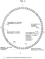
- FIG. 3 shows a schematic configuration of an upper surface of the incubator 1 and shows loading positions of reaction containers 2.
- 64 positions indicated by numbers 1 to 64 are prescribed as a plurality of loading positions on the circumference of the upper surface of the incubator 1. Since the incubator 1 is rotatably driven, the positions (corresponding loading holes and reaction containers 2) on the circumference of the incubator 1 rotatably move.
- the plurality of positions particularly includes positions P1, P4, P34, P36, and P47 as positions (prescribed positions in the automatic analyzer) accessible by the dispensing mechanisms 8 and 9 and the transfer mechanism 17.
- the position P1 is a prescribed position (refer to as first dispensing position) at which a sample and a first reagent for biochemical examination are dispensed and stirred.
- the position P4 is a prescribed position (refer to as second dispensing position) at which a sample and a second reaction for biochemical examination are dispensed and stirred.
- the position P34 is a prescribed position at which a reaction container 2 for biochemical examination is loaded.
- the position P36 is a prescribed position at which a reaction container 2 for biochemical examination is unloaded and a reaction container 2 for immunological examination is loaded and unloaded.
- the position P47 is a first dispensing position at which dispensing and stirring are performed for immunological examination.
- the position P55 is a second dispensing position at which dispensing and stirring are performed for immunological examination.
- the configuration shown in FIG. 3 is an example.
- the number of positions on the incubator 1 and optimal values relating to the positions vary depending on various parameters such as a difference between reaction times in different reaction processes, the radii of the trajectories of the dispensing mechanisms 8 and 9, and the arrangement of the transfer mechanism 17.
- the automatic analyzer can access a prescribed position on the incubator 1.
- the nozzle of the dispensing mechanism 8 can access the position P1 and the position P4.
- the nozzle of the dispensing mechanism 9 can access the position P47 and the position P55.
- the transfer mechanism 17 can access the position P34 and the position P36.
- the automatic analyzer performs container status checking (step S1 or step S9 shown in FIG. 9 ) described later at a prescribed position on the incubator 1.
- container status checking step S1 or step S9 shown in FIG. 9
- the dispensing mechanism 8 uses the position P1 and the dispensing mechanism 9 uses the position P47.
- the controller 100 rotatably drives the incubator 1 to sequentially perform the container status checking on all the positions on the incubator 1 by sequentially moving all the positions (corresponding loading holes and reaction containers 2) on the incubator 1 with respect to a prescribed position (for example, the position P1 and the position P47) for the container status checking.
- the automatic analyzer according to the first embodiment performs the container status checking at all the positions (positions P1 to P64) on the incubator 1, while the certainty for the subsequent analysis is emphasized.
- the automatic analyzer according to the first embodiment is not limited thereto and may perform the container status checking at some of the positions on the incubator 1.
- the controller 100 may perform the container status checking at some of the positions based on management information. In this case, it is possible to reduce a period of time required for the container status checking.
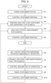
- FIG. 4 shows an example of a process flow relating to overall analysis by the automatic analyzer according to the first embodiment.
- FIG. 4 shows steps S1 to S10, which are described below in the order of the steps.
- the controller 100 performs the container status checking after, for example, activating the device and detects a state of each position on the incubator 1.
- the controller 100 performs container disposal control based on a result of the checking in step S1.
- the controller 100 performs a prescribed analysis preparation process.
- the analysis preparation process includes a process of loading a reaction container 2 onto the incubator 1, a process of dispensing a sample and a reagent into the reaction container 2 to prepare a reaction solution, and the like.
- step S4 the controller 100 uses the reaction solution in the reaction container 2 prepared for analysis to perform an analysis process such as specified biochemical analysis, specified immunoassay, or the like.
- the analysis process includes optical measurement of the reaction solution and a process of analyzing the reaction solution.
- the controller 100 stores a result of the analysis to the storage device 103 and outputs the result of the analysis to the user via the output device 105.
- step S5 the controller 100 performs a disposal operation on the reaction container 2 used for the analysis and a dispensing tip 18 used for the analysis. Steps S3 to S5 are repeated for each reaction container 2 to be analyzed. When the analysis is completed on all reaction containers 2, the flow ends.
- step S7 the controller 100 performs trouble shooting or the like to handle the abnormality.
- the controller 100 provides a GUI screen for guiding a trouble shooting task or a maintenance task or the like to the user. The user performs the maintenance task or the like via the GUI screen or the like to handle the abnormality.
- step S8 the controller 100 confirms that the automatic analyzer changes to a normal state, and performs control to resume the device operation.
- step S9 the controller 100 performs the container status checking in the same manner as step S1 in response to the resumption of the operation.
- step S10 the controller 100 performs the disposal control on the reaction container 2 based on a result of the checking in step S9. After that, the controller 100 causes the process flow to step S3 or S4 and returns to the state before the halt.
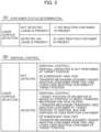
- FIG. 5 shows tables summarizing a control overview according to the first embodiment.
- a table (A) shows an overview of container status determination
- a table (B) shows an overview of the disposal control or the like corresponding to (A).
- one of two rows indicates that a liquid surface is detected by using the liquid surface detection mechanisms of the dispensing mechanisms 8 and 9, and the other of the two rows indicates that a liquid surface is not detected by using the liquid surface detection mechanisms of the dispensing mechanisms 8 and 9.
- Information indicating that a liquid surface is not detected corresponds to a state in which a liquid such as a reaction solution is not present.
- Information indicating that a liquid surface is detected corresponds to a state in which a liquid such as a reaction solution is present.
- An item in each row indicates a value of a state determination result based on a result of detecting a liquid surface.
- the values are two types of state values, which indicate that (1) a "reaction container is not present” and (3) a "used reaction container is present”.
- the controller 100 uses the liquid surface detection mechanisms of the dispensing mechanisms 8 and 9 to detect whether a liquid surface is present or absent at the time of the lowering of the nozzles, and determines, as a status of a reaction container 2 at a target position, a state (1) in which a "reaction container is not present” or a state (3) in which a "used reaction container is present". When a liquid surface is not detected, the controller 100 determines the state (1) in which a "reaction container is not present”.
- the controller 100 determines the state (3) in which a "used reaction container is present".
- the state (1) in which a "reaction container is not present” is a state in which a reaction container 2 is not loaded at a target position.
- the state (3) in which a "used reaction container is present” is a state in which a reaction container 2 storing a reaction solution is loaded.
- an item in each row indicates details of control of the disposal operation and the transfer operation corresponding to determination result values indicated in (A).
- the controller 100 determines that the disposal operation is not required at the target position (corresponding position determined to be a position at which a "reaction position is not present") with regard to the disposal control.
- the disposal operation is an operation of causing the transfer mechanism 17 to access the target position on the incubator 1, grip the reaction container 2, transfer the reaction container 2 to the disposal box 21, and dispose of the reaction container 2.
- the controller 100 controls the transfer mechanism 17 to acquire an unused reaction container 2 from the reaction container tray 20 and transfer and load the reaction container 2 to the target position on the incubator 1 at the time of the subsequent analysis.
- the time of the subsequent analysis corresponds to steps S3 and S4 subsequent to steps S1 and S2 or steps S9 and S10 in FIG. 4 .
- the controller 100 determines that the disposal operation is required at the target position (corresponding position determined to be a position at which a "used reaction container is present") with regard to the disposal control.
- the controller 100 moves the target position on the incubator 1 to a position (position P34 or position P36 in FIG. 3 ) accessible by the transfer mechanism 17.
- the controller 100 controls the transfer mechanism 17 to transfer the used reaction container 2 at the target position to the disposal box 21 and dispose of the reaction container 2.
- the controller 100 controls the transfer mechanism 17 to acquire an unused reaction container 2 from the reaction container tray 20 and load the reaction container 2 to the target position on the incubator 1.
- the liquid surface detection mechanisms included in the dispensing mechanisms 8 and 9 are described with reference to FIG. 6 .
- the automatic analyzer according to the exemplary conventional technique includes a liquid surface detection mechanism in the dispensing mechanism.
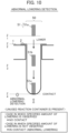
- FIG. 6 is an explanatory diagram relating to liquid surface detection.
- the automatic analyzer according to the first embodiment uses the liquid surface detection mechanisms of the dispensing mechanisms 8 and 9 to determine and detect a status of a reaction container 2.
- a main function and purpose of the liquid surface detection mechanism are to detect a liquid surface in a container to control dispensing (that is, aspiration and discharge of a liquid) at an appropriate position.
- dispensing that is, aspiration and discharge of a liquid
- the amount of a sample stored in an individual sample container may vary depending on the individual sample container at the time of a dispensing operation of aspirating the sample from the sample container. At the time of the dispensing operation, it is preferable to aspirate the sample such that a distal end of a nozzle matches a position on a liquid surface in the sample container.
- the automatic analyzer controls the dispensing mechanism to cause the distal end of the nozzle to follow a position on the liquid surface based on a change in the amount of a liquid to be aspirated and a change in the position on the liquid surface. Therefore, the automatic analyzer according to the exemplary conventional technique uses the liquid surface detection mechanism to detect a state in which the distal end of the nozzle is present at a position on the liquid surface when lowering the nozzle to, for example, the inside of the sample container. The same applies to dispensing of a reagent.
- the liquid surface can be detected by using, for example, an electric circuit to detect and determine a change in electrostatic capacitance.
- the liquid surface detection function is a function of causing liquid surface detection circuits provided in the dispensing mechanisms 8 and 9 to detect, based on a change in electrostatic capacitance, whether distal ends of the nozzles have contacted a liquid surface in a reaction container 2.
- the change in the electrostatic capacitance is equal to or larger than a threshold
- the liquid surface detection function determines that a liquid surface is present.
- the change in the electrostatic capacitance is smaller than the threshold, the liquid surface detection function determines that a liquid surface is not present.
- FIG. 6 schematically shows, for example, the nozzle 51 of the dispensing mechanism 8, a single loading position 50 on the incubator 1, a reaction container 2 loaded at the loading position 50, and the like.
- the loading position 50 corresponds to, for example, a loading hole.
- the shape of the reaction container 2, a method of loading the reaction container 2, and the like are examples and are not limited.
- the controller 100 moves, for example, the nozzle of the dispensing mechanism 8 to the loading position 50 that is a target position in the container status checking.
- the dispensing mechanism 8 moves the nozzle 51 to a position above the loading position 50.
- the position of the distal end of the nozzle 51a is, for example, a position Z1 in the vertical direction.
- the dispensing mechanism 8 lowers the nozzle 51a.
- the nozzle 51a passes through a position Z2 on an upper surface of the reaction container 2 and is lowered.
- This reaction container 2 is a used reaction container 2 storing a reaction solution 52.
- the liquid surface of the reaction solution 52 is at a position Z3, for example.
- the liquid surface detection circuit detects a change in the electrostatic capacitance at this time, thereby determining that the liquid surface is present.
- FIG. 7 shows a process flow relating to the container status checking (step S1 or S9 of FIG. 4 ) and the disposal control (step S2 or S10) in the automatic analyzer according to the first embodiment.
- FIG. 7 shows steps S31 to S38, which are described below in the order of the steps.
- a function according to the first embodiment uses the liquid surface detection mechanisms included in the dispensing mechanisms 8 and 9 to recognize presence or absence of a reaction container 2 at each target position and a usage status (presence or absence of a used reaction container) of the reaction container 2, and determines a detail (whether the disposal operation is required or the like) of the disposal control of the reaction container 2 or the like based on the recognition.
- step S31 the controller 100 moves, for example, the nozzle of the dispensing mechanism 8 to a position above a reaction container 2 loading position (for example, the position P1 shown in FIG. 3 ) on the incubator 1 and causes the dispensing mechanism 8 to start lowering the nozzle by a prescribed amount at the loading position.
- the prescribed amount is a set value.
- step S32 the controller 100 causes the liquid surface detection mechanism of the dispensing mechanism 8 to detect whether the nozzle has detected a liquid surface at the loading position during the lowering.
- the process flow is branched based on the result of the detection in step S32.
- the process flow proceeds to step S33.
- the nozzle of the dispensing mechanism 8 detects the liquid surface at the reaction container loading position during the lowering, that is, when the liquid surface is detected (Y)
- the process flow proceeds to step S35.
- step S33 the controller 100 determines a state in which a reaction container 2 is not loaded at the loading position, that is, the state (1) in which a "reaction container is not present", and the process flows proceeds to step S34.
- step S34 the controller 100 determines that the disposal operation of disposing of the reaction container 2 at the loading position by the transfer mechanism 17 is not required.
- step S35 the controller 100 determines a state in which a reaction container 2 storing a reaction solution is loaded at the loading position, that is, the state (3) in which an "unused reaction container is present", the process flow proceeds to step S36.
- step S36 the controller 100 determines that the disposal operation of disposing of the reaction container 2 at the loading position by the transfer mechanism 17 is required.
- step S37 the controller 100 confirms whether statuses of reaction containers 2 at all the loading positions on the incubator 1 have been completely confirmed by using the liquid surface detection mechanism of the aforementioned dispensing mechanism 8.
- step S38 the controller 100 rotatably drives the incubator 1 to move an unconfirmed loading position to the position (position P1) at which the nozzle of the dispensing mechanism 8 is lowered. After that, the process flow returns to step S31.
- the container status checking is not limited thereto. Even when the dispensing mechanism 9 is used or even when the dispensing mechanisms 8 and 9 are simultaneously used, the same function can be implemented. In addition, even when the automatic analyzer includes a liquid surface detection mechanism as well as the dispensing mechanisms 8 and 9, the same function can be implemented using the liquid surface detection mechanism.
- the automatic analyzer according to the first embodiment can efficiently use and dispose of the reaction containers 2.
- the automatic analyzer according to the first embodiment can use the liquid surface detection mechanisms included in the dispensing mechanisms 8 and 9 to determine statuses of the reaction containers 2 at the loading positions on the incubator 1 as the container status checking and perform the disposal operation of disposing of the reaction containers 2 at the loading positions on the incubator 1 in different manners.
- the disposal operation may not be performed by the transfer mechanism 17 at a position determined to be in the state in which a "reaction container is not present". Therefore, it is possible to improve the overall efficiency of the disposal operation and reduce a period of time required until the subsequent analysis is performed.
- a dedicated liquid surface detection sensor is not required to be provided on the incubator 1 or the like, and an existing mechanism can be used to implement the functions with low cost.
- FIGS. 8 to 10 An automatic analyzer according to a second embodiment is described with reference to FIGS. 8 to 10 .
- a basic configuration according to the second embodiment is the same as or similar to that according to the first embodiment, and constituent components according to the second embodiment that are different from the first embodiment are described below.
- the automatic analyzer according to the second embodiment has a function of detecting statuses of the reaction containers while distinguishing between the used reaction container and the unused rection container and of performing control to perform a disposal operation and the like at positions in different manners.
- the automatic analyzer according to the second embodiment uses liquid surface detection mechanisms and abnormal lowering detection mechanisms included in dispensing mechanisms to determine a status including a usage status of a reaction container at each position on the reaction container retaining mechanism (corresponding incubator).
- a controller determines, as statuses, at least a state in which a used reaction container storing a reaction solution is loaded and a state in which an unused reaction container not storing a reaction solution is loaded. Then, the automatic analyzer according to the second embodiment determines and controls the disposal operation and the like for each position based on the statuses that are the results of the determination.
- the automatic analyzer according to the second embodiment uses the liquid surface detection mechanisms included in the dispensing mechanisms 8 and 9 to detect the status of a reaction container 2 at each loading position and uses the abnormal lowering detection mechanisms included in the dispensing mechanisms 8 and 9 to detect the status of the reaction container 2 at each loading position.
- the automatic analyzer according to the second embodiment 2 combines results of the detection by the liquid surface detection mechanisms with results of the detection by the abnormal lowering detection mechanisms to determine the usage status of the reaction container 2 at each loading position.
- FIG. 8 shows tables indicating a control overview according to the second embodiment.
- the table (A) shows an overview of container status checking
- the table (B) shows an overview of disposal control corresponding to (A) and the like.
- one of two rows indicates that a liquid surface is detected by using the liquid surface detection mechanisms
- the other of the two rows indicates that a liquid surface is detected by using the liquid surface detection mechanisms
- one of two columns indicates that abnormal lowering is detected by using the abnormal lowering detection mechanisms
- the other of the two columns indicates that abnormal lowering is not detected by using the abnormal lowering detection mechanisms.
- Information indicating that a liquid surface is not detected corresponds to a state in which a liquid such as a reaction solution is not present.
- Information indicating that a liquid surface is detected corresponds to a state in which a liquid such as a reaction solution is present.
- Information indicating that abnormal lowering is not detected corresponds to a state in which there is no contact and a reaction container is not present.
- Information indicating that abnormal lowering is detected corresponds to a state in which there is contact and a reaction container is present.
- Items in which the rows and the columns intersect indicate values of status determination results corresponding to combinations of the results of the two types of detection.
- the values are values of three types of states, a state (1) in which a "reaction container is not present", a state (2) in which an "unused reaction container is present", and a state (3) in which a "used reaction container is present".
- the states (1) and (3) are the same as the states described in the first embodiment ( FIG. 5 ). In the second embodiment, the state (2) is added.
- the controller 100 determines the state (1) in which a "reaction container is not present”. When a liquid surface is not detected and abnormal lowering is detected, the controller 100 determines the state (2) in which an "unused reaction container is present”. When a liquid surface is detected, the controller 100 determines the state (3) in which a "used reaction container is present” regardless of whether abnormal lowering is detected.
- the determination that a liquid surface is not detected corresponds to the prediction that a reaction container 2 is not loaded or that a reaction container 2 is loaded but a liquid such as a reaction solution is not present in the reaction container 2, since there is no liquid surface.
- the determination that abnormal lowering is not detected corresponds to the prediction that an object that blocks the operation of lowering the nozzle is not present, that is, the prediction that a bottom surface of a reaction container 2 is not present or an object or the like is not present on the bottom surface, since the nozzle was lowered by a prescribed amount. Therefore, the controller 100 determines the state (1) in which a "reaction container is not present" based on the aforementioned two determination results.
- the controller 100 determines the state (2) in which an "unused reaction container is present" based on the aforementioned two determination results.
- the determination that a liquid surface is detected corresponds to the prediction that a reaction container 2 storing a reaction solution is loaded at a loading position. When a liquid surface is detected, the detection and determination of abnormal lowering is not required. Therefore, in this case, the controller 100 determines the state (3) in which a "used reaction container is present".
- the controller 100 does not perform the disposal operation at a target position (corresponding position determined to be a position at which an "unused reaction container is present") with regard to the disposal control.
- the controller 100 performs control to use the unused reaction container 2 loaded at the target position on the incubator 1 at the time of the subsequent analysis.
- the controller 100 controls the transfer mechanism 17 such that the transfer mechanism 17 does not transfer and load a new reaction container 2 to the target position from the reaction container tray 20.
- FIG. 9 shows a process flow relating to the container status checking and the disposal control in the automatic analyzer according to the second embodiment.
- FIG. 9 shows steps S41 to S50, which are described below in the order of the steps. Steps S41, S42, and S47 to S50 are the same as or similar to steps S31 to S38 shown in FIG. 7 , and steps S43 to S46 are mainly included as different steps.
- the controller 100 performs the aforementioned liquid surface detection in steps S41 and S42. When a liquid surface is not detected (N), the process flow proceeds to step S43.
- step S43 the controller 100 uses the abnormal lowering detection mechanism of the dispensing mechanism 8 to detect whether abnormal lowering (that is, contact) is detected during the lowering of the nozzle at a loading position.
- abnormal lowering that is, contact
- step S44 When abnormal lowering is not detected (N), the process flow proceeds to step S44.
- step S46 When abnormal lowering is detected (Y), the process flow proceeds to step S46.
- the transition to step S44 corresponds to the case in which a liquid surface is not detected and abnormal lowering is not detected as shown in FIG. 8 .
- the transition to step S46 corresponds to the case in which a liquid surface is not detected and abnormal lowering is detected as shown in FIG. 8 .
- step S44 the controller 100 determines the state (1) in which a "reaction container is not present" at the loading position.
- step S45 the controller 100 determines that the disposal operation is not required at the loading position.
- step S46 the controller 100 determines the state (2) in which an "unused reaction container is present” at the loading position. Then, the process flow proceeds to step S45 and the controller 100 determines that the disposal operation is not required at the loading position in the same manner.
- the automatic analyzer according to the second embodiment can efficiently control the disposal and use of a reaction container 2.
- the automatic analyzer according to the second embodiment uses the liquid surface detection mechanisms and the abnormal lowering detection mechanisms of the dispensing mechanisms 8 and 9 to determine a usage status of each reaction container 2 at each loading position on the incubator 1.
- the controller 100 determines that an unused reaction container 2 is present at a loading position, the controller 100 omits the disposal operation at the loading position and performs control to use the reaction container 2 as it is at the time of the subsequent analysis.
- the controller 100 performs control such that an operation of transferring a new reaction container to the loading position is not performed.
Landscapes
- Physics & Mathematics (AREA)
- Health & Medical Sciences (AREA)
- Life Sciences & Earth Sciences (AREA)
- Chemical & Material Sciences (AREA)
- Analytical Chemistry (AREA)
- Biochemistry (AREA)
- General Health & Medical Sciences (AREA)
- General Physics & Mathematics (AREA)
- Immunology (AREA)
- Pathology (AREA)
- Engineering & Computer Science (AREA)
- Quality & Reliability (AREA)
- Automatic Analysis And Handling Materials Therefor (AREA)
Claims (6)
- Automatischer Analysator, umfassend:eine Steuerung (100), die konfiguriert ist, um die Analyse einer Probe zu steuern;einen Behälterhaltemechanismus (1), auf den eine Vielzahl von Behältern (2) an einer Vielzahl von Positionen geladen werden kann;einen Entsorgungskasten (21) zum Aufbewahren von entsorgten Behältern (2);einen Abgabemechanismus (8, 9), der konfiguriert ist, um die Probe und ein Reagens an den Behälter (2) abzugeben;einen Erfassungsmechanismus (16), der konfiguriert ist, um eine Komponente aus einer Reaktionslösung zu erfassen, die durch Abgeben der Probe und des Reagens an den Behälter (2) hergestellt wird; undeinen Übertragungsmechanismus (17), der konfiguriert ist, um den Behälter (2) an den Entsorgungskasten (21) zu übertragen, wenn der Behälter (2) an einer Position auf dem Behälterhaltemechanismus (1) geladen werden soll und wenn der Behälter (2) an der Position entsorgt werden soll, dadurch gekennzeichnet, dass:der Abgabemechanismus (8, 9) einen Flüssigkeitsoberflächenerfassungsmechanismus beinhaltet, der konfiguriert ist, um eine Flüssigkeitsoberfläche einer Flüssigkeit in dem Behälter (2) zu erfassen, und einen anormalen Absenkungserfassungsmechanismus beinhaltet, der konfiguriert ist, um eine Anormalität einer Düse beim Absenken zu erfassen;die Steuerung (100) konfiguriert ist, um:
den Abgabemechanismus (8, 9) zu einem vorgeschriebenen Zeitpunkt zu verwenden, um das Vorhandensein oder Nichtvorhandensein der Flüssigkeitsoberfläche an einer Zielposition auf dem Behälterhaltemechanismus (1) zu erfassen und eine Anormalität beim Absenken der Düse zu erfassen; wobei die Steuerung (100) ferner konfiguriert ist, um:einen Zustand einschließlich des Vorhandenseins oder Nichtvorhandenseins des Behälters (2) und einen Zustand einschließlich des verwendeten oder nicht verwendeten Behälters basierend auf dem erfassten Vorhandensein oder Nichtvorhandensein der Flüssigkeitsoberfläche an der Zielposition und dem Erfassen oder Nichterfassen einer Anormalität beim Absenken der Düse zu bestimmen; undeine Steuerung durchzuführen, um die Entsorgung unter Verwendung des Übertragungsmechanismus (17) an der Position zu bewirken, wenn die Steuerung (100) einen Zustand bestimmt, in dem der Behälter (2) vorhanden und verwendet ist, odereine Steuerung durchzuführen, um die Entsorgung unter Verwendung des Übertragungsmechanismus (17) an der Position nicht zu bewirken, wenn die Steuerung (100) einen Zustand bestimmt, in dem der Behälter (2) nicht vorhanden oder nicht verwendet ist. - Automatischer Analysator nach Anspruch 1,
wobei an der Position, wenn ein Zustand bestimmt wird, in dem der Behälter (2) nicht vorhanden ist, die Steuerung (100) eine Steuerung durchführt, in der die Steuerung (100) den Vorgang des Ladens des Behälters (2), der neu ist, unter Verwendung des Übertragungsmechanismus (17) vor der nachfolgenden Analyse durchführt. - Automatischer Analysator nach Anspruch 1,
wobei der vorgeschriebene Zeitpunkt die Zeit der Aktivierung des Analysators und die Zeit der Wiederaufnahme des Analysatorbetriebs nach dem Anhalten des Analysatorbetriebs aufgrund der Erfassung einer Analysatoranormalität beinhaltet. - Automatischer Analysator nach Anspruch 1,
wobei der Flüssigkeitsoberflächenerfassungsmechanismus ein Mechanismus ist, der konfiguriert ist, um das Vorhandensein oder Nichtvorhandensein der Flüssigkeitsoberfläche basierend auf einer Änderung der elektrostatischen Kapazität zu erfassen, die einem Kontakt einer Düse des Abgabemechanismus (8, 9) mit der Flüssigkeitsoberfläche entspricht. - Automatischer Analysator nach Anspruch 1,
wobei der anormale Absenkungserfassungsmechanismus ein Mechanismus ist, der konfiguriert ist, um einen Zustand der Anormalität basierend auf der Erfassung eines Kontakts der Düse des Abgabemechanismus (8, 9) mit einer Bodenfläche des Behälters (2) oder mit einem anderen Objekt zu erfassen. - Automatischer Analysator nach Anspruch 1,
wobei die Steuerung (100) die Düse des Abgabemechanismus (8, 9) veranlasst, Zugang zu einer vorbestimmten Position auf dem Behälterhaltemechanismus (1) zu dem vorgeschriebenen Zeitpunkt zu machen, um den Behälterhaltemechanismus (1) zu drehen, und alle Positionen oder ein Teil von Positionen in der Vielzahl von Positionen wiederum zu der vorbestimmten Position bewegt werden.
Applications Claiming Priority (2)
| Application Number | Priority Date | Filing Date | Title |
|---|---|---|---|
| JP2019095250 | 2019-05-21 | ||
| PCT/JP2020/002083 WO2020235134A1 (ja) | 2019-05-21 | 2020-01-22 | 自動分析装置 |
Publications (3)
| Publication Number | Publication Date |
|---|---|
| EP3974837A1 EP3974837A1 (de) | 2022-03-30 |
| EP3974837A4 EP3974837A4 (de) | 2023-03-29 |
| EP3974837B1 true EP3974837B1 (de) | 2025-07-09 |
Family
ID=73459442
Family Applications (1)
| Application Number | Title | Priority Date | Filing Date |
|---|---|---|---|
| EP20808286.7A Active EP3974837B1 (de) | 2019-05-21 | 2020-01-22 | Automatische analysevorrichtung |
Country Status (5)
| Country | Link |
|---|---|
| US (1) | US12352772B2 (de) |
| EP (1) | EP3974837B1 (de) |
| JP (1) | JP7189339B2 (de) |
| CN (1) | CN113785205B (de) |
| WO (1) | WO2020235134A1 (de) |
Families Citing this family (5)
| Publication number | Priority date | Publication date | Assignee | Title |
|---|---|---|---|---|
| EP4191250A4 (de) * | 2020-07-28 | 2024-07-10 | Hitachi High-Tech Corporation | Automatische analysevorrichtung |
| US20240012019A1 (en) | 2020-12-11 | 2024-01-11 | Hitachi High-Tech Corporation | Automatic analyzer |
| US20220268796A1 (en) * | 2021-02-19 | 2022-08-25 | Roche Molecular Systems, Inc. | Method of Operating a Laboratory Instrument |
| JP7779206B2 (ja) * | 2022-06-22 | 2025-12-03 | 横河電機株式会社 | 分注装置、分注方法及び分注プログラム |
| CN115963286B (zh) * | 2022-12-26 | 2023-10-10 | 广州市进德生物科技有限公司 | 一种可连续检测多功能发光读数站 |
Family Cites Families (36)
| Publication number | Priority date | Publication date | Assignee | Title |
|---|---|---|---|---|
| US5215714A (en) | 1988-04-08 | 1993-06-01 | Toa Medical Electronics Co., Ltd. | Immunoagglutination measurement apparatus |
| JP2761385B2 (ja) | 1988-04-08 | 1998-06-04 | 東亜医用電子株式会社 | 免疫凝集測定装置 |
| JPH08313538A (ja) * | 1995-05-22 | 1996-11-29 | Mitsubishi Corp | 自動分析装置 |
| JPH11352131A (ja) * | 1998-06-05 | 1999-12-24 | Hitachi Ltd | 自動分析装置 |
| JP2000046841A (ja) * | 1998-07-31 | 2000-02-18 | Tosoh Corp | 自動測定装置 |
| JP2000346853A (ja) * | 1999-06-09 | 2000-12-15 | Hitachi Ltd | 入力信号判別回路を用いた自動分析装置 |
| US8012768B2 (en) * | 2003-07-18 | 2011-09-06 | Bio-Rad Laboratories, Inc. | System and method for multi-analyte detection |
| EP2295983B1 (de) * | 2005-09-26 | 2018-07-18 | QIAGEN GmbH | Vorrichtung zur Behandlung von biologischem Material |
| EP2017625A1 (de) * | 2006-05-11 | 2009-01-21 | Olympus Corporation | Analyseautomat |
| JP2007316010A (ja) * | 2006-05-29 | 2007-12-06 | Olympus Corp | 容器の廃棄方法および自動分析装置 |
| JP2008026051A (ja) * | 2006-07-19 | 2008-02-07 | Furuno Electric Co Ltd | 生化学自動分析装置 |
| DE102007014083A1 (de) * | 2007-03-21 | 2008-09-25 | Dade Behring Marburg Gmbh | Verfahren zur Verhinderung des mehrfachen Gebrauchs von Einmalartikeln in Analysegeräten |
| JP5220014B2 (ja) * | 2007-07-18 | 2013-06-26 | ベックマン コールター, インコーポレイテッド | 分析装置とその異常対処方法 |
| JP5486160B2 (ja) * | 2008-02-27 | 2014-05-07 | シスメックス株式会社 | 検体分析装置及びその異常制御方法、並びに検体分析装置用プログラム |
| JP5143630B2 (ja) * | 2008-05-22 | 2013-02-13 | シスメックス株式会社 | 分析装置 |
| JP2010096638A (ja) * | 2008-10-17 | 2010-04-30 | Hitachi High-Technologies Corp | 自動分析装置 |
| US20120020838A1 (en) * | 2009-04-09 | 2012-01-26 | Hitachi High-Technologies Corporation | Automatic analysis device and dispensing device |
| JP5372723B2 (ja) * | 2009-12-15 | 2013-12-18 | 株式会社日立ハイテクノロジーズ | 自動分析装置 |
| US20120251391A1 (en) | 2009-12-21 | 2012-10-04 | Hitachi High-Technologies Corporation | Automatic analyzer |
| CN102192995B (zh) * | 2010-03-11 | 2015-06-10 | 希森美康株式会社 | 试样分析装置和试剂管理方法 |
| JP5613522B2 (ja) * | 2010-10-12 | 2014-10-22 | シスメックス株式会社 | 検体分析装置 |
| JP5872816B2 (ja) * | 2011-08-03 | 2016-03-01 | シスメックス株式会社 | 検体分析装置 |
| WO2013070754A1 (en) * | 2011-11-07 | 2013-05-16 | Beckman Coulter, Inc. | Robotic arm |
| BR112014011043A2 (pt) * | 2011-11-07 | 2017-06-13 | Beckman Coulter Inc | detecção de recipiente de espécime |
| JP6026753B2 (ja) * | 2012-02-23 | 2016-11-16 | 株式会社日立ハイテクノロジーズ | 自動分析装置 |
| EP3276358A1 (de) * | 2012-06-11 | 2018-01-31 | Hitachi High-Technologies Corporation | Automatischer analysator |
| JP5993737B2 (ja) * | 2012-12-17 | 2016-09-14 | 株式会社日立ハイテクノロジーズ | 自動分析装置 |
| WO2015105079A1 (ja) * | 2014-01-07 | 2015-07-16 | 株式会社日立ハイテクノロジーズ | 自動分析装置 |
| JP6338898B2 (ja) | 2014-03-17 | 2018-06-06 | キヤノンメディカルシステムズ株式会社 | 自動分析装置 |
| JP6320535B2 (ja) * | 2014-07-29 | 2018-05-09 | 株式会社日立ハイテクノロジーズ | 自動分析装置 |
| WO2016084462A1 (ja) * | 2014-11-25 | 2016-06-02 | 株式会社 日立ハイテクノロジーズ | 自動分析装置 |
| JP6649942B2 (ja) * | 2015-02-23 | 2020-02-19 | 株式会社日立ハイテクノロジーズ | 自動分析装置 |
| JP6698665B2 (ja) * | 2015-09-17 | 2020-05-27 | 株式会社日立ハイテク | 自動分析装置 |
| JP6771903B2 (ja) * | 2016-02-29 | 2020-10-21 | シスメックス株式会社 | 検体前処理装置、検体前処理カートリッジおよび検体前処理方法 |
| EP3255436B1 (de) * | 2016-06-06 | 2022-09-21 | F. Hoffmann-La Roche AG | Zuführung verbrauchbarer artikel an einen automatisierten probenanalysator |
| EP3677916B1 (de) * | 2018-01-26 | 2023-07-12 | Hitachi High-Tech Corporation | Automatisierter analysator |
-
2020
- 2020-01-22 CN CN202080033263.6A patent/CN113785205B/zh active Active
- 2020-01-22 WO PCT/JP2020/002083 patent/WO2020235134A1/ja not_active Ceased
- 2020-01-22 EP EP20808286.7A patent/EP3974837B1/de active Active
- 2020-01-22 JP JP2021520043A patent/JP7189339B2/ja active Active
- 2020-01-22 US US17/594,436 patent/US12352772B2/en active Active
Also Published As
| Publication number | Publication date |
|---|---|
| JPWO2020235134A1 (de) | 2020-11-26 |
| US12352772B2 (en) | 2025-07-08 |
| JP7189339B2 (ja) | 2022-12-13 |
| CN113785205B (zh) | 2024-06-11 |
| EP3974837A4 (de) | 2023-03-29 |
| EP3974837A1 (de) | 2022-03-30 |
| CN113785205A (zh) | 2021-12-10 |
| US20220178960A1 (en) | 2022-06-09 |
| WO2020235134A1 (ja) | 2020-11-26 |
Similar Documents
| Publication | Publication Date | Title |
|---|---|---|
| EP3974837B1 (de) | Automatische analysevorrichtung | |
| JP5178830B2 (ja) | 自動分析装置 | |
| EP1087231B1 (de) | Automatische Analysevorrichtung | |
| JP6320535B2 (ja) | 自動分析装置 | |
| JPH06207944A (ja) | 洗浄機能付き自動分析装置 | |
| WO2016143478A1 (ja) | 自動分析装置 | |
| JP5236612B2 (ja) | 自動分析装置 | |
| WO2012105398A1 (ja) | 自動分析装置 | |
| EP3422017A1 (de) | Automatische analysevorrichtung und reinigungsverfahren | |
| JP6928712B2 (ja) | 自動分析装置 | |
| JP3990943B2 (ja) | 自動分析システム | |
| WO2022176556A1 (ja) | 自動分析装置、および自動分析装置における検体の吸引方法 | |
| JP2011013127A (ja) | 自動分析装置及び自動分析装置の制御方法 | |
| US20240192244A1 (en) | Automatic analyzer | |
| US20190369130A1 (en) | Automatic Analyzer | |
| CN115053137A (zh) | 自动分析装置 | |
| JP5606843B2 (ja) | 自動分析装置 | |
| US20240192242A1 (en) | Automatic Analyzer | |
| WO2023190216A1 (ja) | 自動分析装置 | |
| JP7054616B2 (ja) | 自動分析装置 | |
| US20240012019A1 (en) | Automatic analyzer | |
| JP7114794B1 (ja) | 自動分析装置及び自動分析方法 | |
| JP7614360B2 (ja) | 自動分析装置、および自動分析装置でのガイダンス方法 | |
| JP2025144280A (ja) | 自動分析装置 | |
| WO2025150336A1 (ja) | 自動分析装置及び自動分析方法 |
Legal Events
| Date | Code | Title | Description |
|---|---|---|---|
| STAA | Information on the status of an ep patent application or granted ep patent |
Free format text: STATUS: THE INTERNATIONAL PUBLICATION HAS BEEN MADE |
|
| PUAI | Public reference made under article 153(3) epc to a published international application that has entered the european phase |
Free format text: ORIGINAL CODE: 0009012 |
|
| STAA | Information on the status of an ep patent application or granted ep patent |
Free format text: STATUS: REQUEST FOR EXAMINATION WAS MADE |
|
| 17P | Request for examination filed |
Effective date: 20211221 |
|
| AK | Designated contracting states |
Kind code of ref document: A1 Designated state(s): AL AT BE BG CH CY CZ DE DK EE ES FI FR GB GR HR HU IE IS IT LI LT LU LV MC MK MT NL NO PL PT RO RS SE SI SK SM TR |
|
| DAV | Request for validation of the european patent (deleted) | ||
| DAX | Request for extension of the european patent (deleted) | ||
| A4 | Supplementary search report drawn up and despatched |
Effective date: 20230228 |
|
| RIC1 | Information provided on ipc code assigned before grant |
Ipc: G01N 35/10 20060101ALI20230222BHEP Ipc: G01N 35/00 20060101AFI20230222BHEP |
|
| STAA | Information on the status of an ep patent application or granted ep patent |
Free format text: STATUS: EXAMINATION IS IN PROGRESS |
|
| 17Q | First examination report despatched |
Effective date: 20230925 |
|
| GRAP | Despatch of communication of intention to grant a patent |
Free format text: ORIGINAL CODE: EPIDOSNIGR1 |
|
| STAA | Information on the status of an ep patent application or granted ep patent |
Free format text: STATUS: GRANT OF PATENT IS INTENDED |
|
| INTG | Intention to grant announced |
Effective date: 20250224 |
|
| GRAS | Grant fee paid |
Free format text: ORIGINAL CODE: EPIDOSNIGR3 |
|
| GRAA | (expected) grant |
Free format text: ORIGINAL CODE: 0009210 |
|
| STAA | Information on the status of an ep patent application or granted ep patent |
Free format text: STATUS: THE PATENT HAS BEEN GRANTED |
|
| AK | Designated contracting states |
Kind code of ref document: B1 Designated state(s): AL AT BE BG CH CY CZ DE DK EE ES FI FR GB GR HR HU IE IS IT LI LT LU LV MC MK MT NL NO PL PT RO RS SE SI SK SM TR |
|
| REG | Reference to a national code |
Ref country code: GB Ref legal event code: FG4D |
|
| REG | Reference to a national code |
Ref country code: CH Ref legal event code: EP |
|
| REG | Reference to a national code |
Ref country code: IE Ref legal event code: FG4D |
|
| REG | Reference to a national code |
Ref country code: DE Ref legal event code: R096 Ref document number: 602020054281 Country of ref document: DE |
|
| REG | Reference to a national code |
Ref country code: NL Ref legal event code: MP Effective date: 20250709 |
|
| PG25 | Lapsed in a contracting state [announced via postgrant information from national office to epo] |
Ref country code: PT Free format text: LAPSE BECAUSE OF FAILURE TO SUBMIT A TRANSLATION OF THE DESCRIPTION OR TO PAY THE FEE WITHIN THE PRESCRIBED TIME-LIMIT Effective date: 20251110 |
|
| PG25 | Lapsed in a contracting state [announced via postgrant information from national office to epo] |
Ref country code: NL Free format text: LAPSE BECAUSE OF FAILURE TO SUBMIT A TRANSLATION OF THE DESCRIPTION OR TO PAY THE FEE WITHIN THE PRESCRIBED TIME-LIMIT Effective date: 20250709 |
|
| REG | Reference to a national code |
Ref country code: AT Ref legal event code: MK05 Ref document number: 1812254 Country of ref document: AT Kind code of ref document: T Effective date: 20250709 |
|
| PG25 | Lapsed in a contracting state [announced via postgrant information from national office to epo] |
Ref country code: IS Free format text: LAPSE BECAUSE OF FAILURE TO SUBMIT A TRANSLATION OF THE DESCRIPTION OR TO PAY THE FEE WITHIN THE PRESCRIBED TIME-LIMIT Effective date: 20251109 |
|
| PG25 | Lapsed in a contracting state [announced via postgrant information from national office to epo] |
Ref country code: NO Free format text: LAPSE BECAUSE OF FAILURE TO SUBMIT A TRANSLATION OF THE DESCRIPTION OR TO PAY THE FEE WITHIN THE PRESCRIBED TIME-LIMIT Effective date: 20251009 |
|
| REG | Reference to a national code |
Ref country code: LT Ref legal event code: MG9D |
|
| PG25 | Lapsed in a contracting state [announced via postgrant information from national office to epo] |
Ref country code: AT Free format text: LAPSE BECAUSE OF FAILURE TO SUBMIT A TRANSLATION OF THE DESCRIPTION OR TO PAY THE FEE WITHIN THE PRESCRIBED TIME-LIMIT Effective date: 20250709 |
|
| PG25 | Lapsed in a contracting state [announced via postgrant information from national office to epo] |
Ref country code: FI Free format text: LAPSE BECAUSE OF FAILURE TO SUBMIT A TRANSLATION OF THE DESCRIPTION OR TO PAY THE FEE WITHIN THE PRESCRIBED TIME-LIMIT Effective date: 20250709 |
|
| PG25 | Lapsed in a contracting state [announced via postgrant information from national office to epo] |
Ref country code: HR Free format text: LAPSE BECAUSE OF FAILURE TO SUBMIT A TRANSLATION OF THE DESCRIPTION OR TO PAY THE FEE WITHIN THE PRESCRIBED TIME-LIMIT Effective date: 20250709 |
|
| PG25 | Lapsed in a contracting state [announced via postgrant information from national office to epo] |
Ref country code: GR Free format text: LAPSE BECAUSE OF FAILURE TO SUBMIT A TRANSLATION OF THE DESCRIPTION OR TO PAY THE FEE WITHIN THE PRESCRIBED TIME-LIMIT Effective date: 20251010 |
|
| PG25 | Lapsed in a contracting state [announced via postgrant information from national office to epo] |
Ref country code: SE Free format text: LAPSE BECAUSE OF FAILURE TO SUBMIT A TRANSLATION OF THE DESCRIPTION OR TO PAY THE FEE WITHIN THE PRESCRIBED TIME-LIMIT Effective date: 20250709 |
|
| PG25 | Lapsed in a contracting state [announced via postgrant information from national office to epo] |
Ref country code: LV Free format text: LAPSE BECAUSE OF FAILURE TO SUBMIT A TRANSLATION OF THE DESCRIPTION OR TO PAY THE FEE WITHIN THE PRESCRIBED TIME-LIMIT Effective date: 20250709 |
|
| PG25 | Lapsed in a contracting state [announced via postgrant information from national office to epo] |
Ref country code: PL Free format text: LAPSE BECAUSE OF FAILURE TO SUBMIT A TRANSLATION OF THE DESCRIPTION OR TO PAY THE FEE WITHIN THE PRESCRIBED TIME-LIMIT Effective date: 20250709 Ref country code: BG Free format text: LAPSE BECAUSE OF FAILURE TO SUBMIT A TRANSLATION OF THE DESCRIPTION OR TO PAY THE FEE WITHIN THE PRESCRIBED TIME-LIMIT Effective date: 20250709 |
|
| PG25 | Lapsed in a contracting state [announced via postgrant information from national office to epo] |
Ref country code: RS Free format text: LAPSE BECAUSE OF FAILURE TO SUBMIT A TRANSLATION OF THE DESCRIPTION OR TO PAY THE FEE WITHIN THE PRESCRIBED TIME-LIMIT Effective date: 20251009 |
|
| PG25 | Lapsed in a contracting state [announced via postgrant information from national office to epo] |
Ref country code: ES Free format text: LAPSE BECAUSE OF FAILURE TO SUBMIT A TRANSLATION OF THE DESCRIPTION OR TO PAY THE FEE WITHIN THE PRESCRIBED TIME-LIMIT Effective date: 20250709 |