EP1536208A1 - Drehzahlmesser für Bootsmotoren mit schaltbaren Anzeigemodi - Google Patents
Drehzahlmesser für Bootsmotoren mit schaltbaren Anzeigemodi Download PDFInfo
- Publication number
- EP1536208A1 EP1536208A1 EP04025206A EP04025206A EP1536208A1 EP 1536208 A1 EP1536208 A1 EP 1536208A1 EP 04025206 A EP04025206 A EP 04025206A EP 04025206 A EP04025206 A EP 04025206A EP 1536208 A1 EP1536208 A1 EP 1536208A1
- Authority
- EP
- European Patent Office
- Prior art keywords
- mode
- speed
- engine
- engine speed
- trolling
- Prior art date
- Legal status (The legal status is an assumption and is not a legal conclusion. Google has not performed a legal analysis and makes no representation as to the accuracy of the status listed.)
- Granted
Links
- 239000000498 cooling water Substances 0.000 claims description 11
- XLYOFNOQVPJJNP-UHFFFAOYSA-N water Substances O XLYOFNOQVPJJNP-UHFFFAOYSA-N 0.000 claims description 11
- 238000009825 accumulation Methods 0.000 claims description 4
- 241000251468 Actinopterygii Species 0.000 description 2
- 238000010586 diagram Methods 0.000 description 2
- 238000012935 Averaging Methods 0.000 description 1
- 239000000446 fuel Substances 0.000 description 1
- 238000000034 method Methods 0.000 description 1
Images



Classifications
-
- G—PHYSICS
- G01—MEASURING; TESTING
- G01D—MEASURING NOT SPECIALLY ADAPTED FOR A SPECIFIC VARIABLE; ARRANGEMENTS FOR MEASURING TWO OR MORE VARIABLES NOT COVERED IN A SINGLE OTHER SUBCLASS; TARIFF METERING APPARATUS; MEASURING OR TESTING NOT OTHERWISE PROVIDED FOR
- G01D3/00—Indicating or recording apparatus with provision for the special purposes referred to in the subgroups
- G01D3/02—Indicating or recording apparatus with provision for the special purposes referred to in the subgroups with provision for altering or correcting the law of variation
- G01D3/024—Indicating or recording apparatus with provision for the special purposes referred to in the subgroups with provision for altering or correcting the law of variation for range change; Arrangements for substituting one sensing member by another
-
- G—PHYSICS
- G01—MEASURING; TESTING
- G01D—MEASURING NOT SPECIALLY ADAPTED FOR A SPECIFIC VARIABLE; ARRANGEMENTS FOR MEASURING TWO OR MORE VARIABLES NOT COVERED IN A SINGLE OTHER SUBCLASS; TARIFF METERING APPARATUS; MEASURING OR TESTING NOT OTHERWISE PROVIDED FOR
- G01D7/00—Indicating measured values
- G01D7/02—Indicating value of two or more variables simultaneously
Definitions
- the invention relates to a boat indicator comprising an engine speed indicating section. Further, the invention relates to a boat having a hull and at least one engine.
- a conventional boat having an outboard motor or the like is provided with a boat indicator for indicating engine speed.
- the boat indicator can indicate engine speed of approximately 100rpm or higher (or the number with hundred's place or greater) with low display resolution in order for a user to read the engine speed at a glance.
- Some boats are configured to run in a normal (high-speed) mode and, additionally, in a trolling mode at a low speed.
- the trolling mode which is used, e.g. while fishing, is a specific mode unique to boats and not used at other types of vehicles.
- the setting of the engine speed in the trolling running covers more precise preset values compared to those indicated by the display resolution.
- the conventional indicator has a fixed display resolution which can only indicate engine speed equal to or higher than approximately 100 rpm. It is therefore difficult for a user to identify if the engine speed shown by the indicator is close to the preset engine speed.
- the engine speed indicating section is adapted to switch display modes between a first display mode for indicating an engine speed during a normal-speed mode and a second display mode for indicating an engine speed during a low-speed trolling mode, according to a running mode selection.
- the preset value of the engine speed is displayed at the level of lower speed range. This allows a driver to identify if the engine speed shown by the indicator is close to the preset engine speed.
- the engine speed indicating section does not display velocities and others but does only engine speeds in normal mode or trolling mode. This enables the driver to easily recognize them.
- the engine speed indicating section is configured to indicate the engine speed in the normal-speed mode with a first resolution and to indicate the engine speed in the low-speed trolling mode with a second resolution at a level of a lower speed range than the first resolution.
- an engine condition indicating section is provided, preferably being arranged next to the engine speed indicating section, said engine condition indicating section being adapted to switch display modes, in particular according to the running mode selection.
- said engine condition indicating section is adapted to indicate texts, values and/or levels for at least one parameter or mode, in particular regarding an engine condition such as a cooling water temperature, a residual battery capacity, a battery voltage, a water accumulation amount, an oil pressure, an oil amount, and/or an engine speed.
- an engine condition such as a cooling water temperature, a residual battery capacity, a battery voltage, a water accumulation amount, an oil pressure, an oil amount, and/or an engine speed.
- said engine condition indicating section is adapted to indicate an engine condition during a normal-speed running mode and/or to indicate an engine speed during the low-speed trolling mode.
- said engine condition indicating section is adapted to indicate an engine condition indication mark, an engine condition range, and/or an engine condition value during a normal-speed running mode.
- said engine condition indicating section is adapted to indicate a trolling mode display for indicating that the trolling mode is currently selected and/or the preset trolling engine speed during the low-speed trolling mode.
- the boat indicator comprises a mode selection switch for switching the running mode between the trolling mode and the normal mode.
- the boat indicator comprises an engine-speed changing switch for changing a preset trolling engine speed in the low-speed trolling mode.
- the boat indicator is connected to a further boat indicator, preferably via a local area network, the boat indicator being configured in that a change of the running mode selection performed at the boat indicator causes an automatic and corresponding change of the running mode selection at the further boat indicator.
- the object is solved in an inventive manner in that it comprises a boat indicator according to at least one of the claims 1 to 10.
- FIGs. 1 through 6 show embodiments of the present invention.
- a reference numeral 11 denotes a hull.
- four indicators 12 are disposed in front of a driver's seat on the hull 11.
- the rear of the hull 11 is provided with four outboard motors 13. These multiple outboard motors 13 and indicators 12 are connected to each other via a Local Area Network (LAN).
- LAN Local Area Network
- each indicator 12 is provided with an indicating section 14 for indicating various data, such as engine speed and cooling water temperature, while a mode selection switch 15 and a setting switch 16 are provided below the indicating section 14.
- the mode selection switch 15 allows switching the running mode between low-speed trolling mode and normal mode at a speed higher than the trolling mode.
- These mode selection switch 15 and setting switch 16 also allow changing of the preset trolling engine speed, which are referred to as "engine-speed changing switches.”
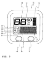
- the indicating section 14 is roughly constructed with of an engine speed indicating section 18 for indicating engine speed, a trim position indicating section 19 for indicating trim position of the outboard motor 13, and an engine condition indicating section 20 for indicating the state of the trolling mode and cooling water temperature etc.
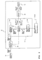
- the indicating section 14 and the switches 15, 16 are connected to and controlled by a central processing unit (hereinafter referred to as "CPU") 17 as will be described below.
- CPU central processing unit
- to keep pressing the mode selection switch 15 for a predetermined period of time allows transmitting of a mode selection signal to the outboard motor 13 through the CPU 17 to set the running mode at the low-speed trolling mode.
- to keep pressing the mode selection switch 15 allows transmitting of a mode selection signal to the outboard motor 13 through the CPU 17 to switch the trolling mode to normal mode for higher-speed running.
- the engine speed in trolling mode is adjusted on the outboard motor 13 by controlling an idle speed control (ISC) valve.
- ISC idle speed control
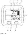
- the engine speed indicating section 18 is designed to switch display modes, according to the running mode selection, between the normal mode display for indicating the engine speed in normal mode (See FIG. 4) and the trolling mode display for indicating the low engine speed in trolling mode (See FIG. 5).
- the normal mode display on the engine speed indicating section 18 indicates engine speed detected with a first resolution (1( ⁇ 100r/min)).
- the engine revolution speed per minute is indicated as a value having a number in the hundred's place or a larger-place value (in a range between 0 and 99 ( ⁇ 100 r/min)).
- [53 ⁇ 100r/min] is indicated as shown in FIG. 4.
- the trolling mode display on the engine speed indicating section 18 indicates engine speed detected with a second resolution (50(r/min)) at the level of lower speed range than the first resolution.
- the engine revolution speed per minute is indicated as a value having a number in the one's place or a larger place value (in a range between 000 and 999 (r/min)). For example, [750 r/min] is indicated as shown in FIG. 5.
- trim position indicating section 19 formed next to the engine speed indicating section 18, is designed to indicate a trim position and trim tab position at one of the 10 position levels.
- the engine condition indicating section 20 is provided with a multi-indication section 21 on which values for various parameters, levels and texts are indicated.
- the engine condition indicating section 20 provides a water pressure mark 22 which is indicated on selecting the water pressure mode and flashes at abnormally low cooling water temperature; a water temperature mark 23 which is indicated on selecting the water temperature mode and flashes at abnormally high water temperature; a water accumulation mark 24 which flashes when water accumulation is detected in a fuel filter; a voltage mark 25 which is indicated on selecting the electric voltage mode and flashes at abnormally low battery voltage; an oil amount mark 26 designed for two-stroke engines which is indicated on selecting the oil amount mode and flashes at low amount of oil; and an oil pressure mark 27 designed for four-stroke engines which is indicated on selecting the oil pressure mode and flashes at abnormally low oil pressure.
- the engine condition indicating section 20 is designed to switch display modes, according to the running mode selection, between the normal mode display for indicating cooling water temperature, residual battery capacity and the like in normal mode, and the trolling mode display for indicating that the trolling mode is currently selected, and the preset trolling engine speed in trolling mode.
- the normal mode display on the engine condition indicating section 20 provides the water temperature mark 23, the voltage mark 25 and the oil amount mark 26 while providing the cooling water temperature, residual battery capacity and oil amount in the multi-indication section 21.
- the trolling mode display on the engine condition indicating section 20 indicates [TROLL 750r/m] in the multi-indication section 21, for example as shown in FIG. 5.
- the preset trolling engine speed in trolling mode is designed to be variable so that it can increase by 50 rpm each time pressing the mode selection switch 15 for a predetermined period of time (not longer than 1.5 seconds) or decrease by 50 rpm each time pressing the setting switch 16 for a predetermined period of time (not longer than 1.5 seconds).
- engine speed data is transmitted from the outboard motor 13 to the indicator 12 through the LAN and then inputted to an averaging processing section 30 in the CPU 17 through a transmitter/receiver module 29 in the indicator 12. This averaged engine speed data is inputted to an indication processing section 31.
- the indication processing section 31 processes the aforementioned engine speed data at low resolution (first resolution). This data is transmitted to an indication driver 32 from which a control signal is outputted to the indicating section 14.
- the engine speed indicating section 18 in the indicating section 14 indicates [53 ⁇ 100r/min] for example as shown in FIG. 4.
- the engine condition indicating section 20 indicates the water temperature mark 23, the voltage mark 25 and the oil amount mark 26 while the multi-indication section 21 indicates the cooling water temperature, residual battery capacity and oil amount.
- operating the mode selection switch 15 to switch to the trolling mode allows inputting a trolling mode signal to the indication processing section 31 through a key switch input processing section 33.
- the indication processing section 31 is therefore switched to processing at high resolution (second resolution).
- the engine speed data processed at high resolution is transmitted to an indication driver 32 from which a control signal is outputted to the indicating section 14.
- the engine speed indicating section 18 in the indicating section 14 indicates [750r/min] for example as shown in FIG. 5.
- the engine condition indicating section 20 in the indicating section 14 is switched to the trolling mode display and then indicates [TROLL 750r/m] as shown in FIG. 5 for example.
- the trolling mode display indicates engine speeds lower than those shown on the normal mode display. Based on these indicated values, a driver can appropriately control the lower engine speed in trolling mode. This allows adjusting the running speed in trolling mode to a desirable speed, which can lead to more successful fishing.
- the engine speed indicating section 18 does not display velocities and others but does only engine speeds in normal mode or trolling mode. This enables the driver to easily recognize them.
- the engine condition indicating section 20 is designed to switch display modes, according to each mode selection, between the normal mode display for indicating the cooling water temperature, battery residual capacity and the like in normal mode, and the trolling mode display for indicating that the trolling mode is currently selected and the preset trolling engine speed in trolling mode. Viewing these displays allows the driver to easily recognize the current mode.
- indicating the preset trolling engine speed allows the driver to easily recognize the current preset engine speed. Furthermore, the driver can easily compare this current preset engine speed with the actual engine speed so that the driver can make sure if the engine is in operation at the preset value.
- the indicator 12 has the mode selection switch 15 for switching running mode between trolling mode and normal mode. This allows the driver to easily switch the running mode using this switch 15 while viewing the indicating section 14.
- the indicator has not only the mode selection switch 15, but also the setting switch 16, in order to change the preset trolling engine speed in trolling mode. This allows the driver to easily change the preset trolling engine speed using these switches 15, 16, while viewing the indicating section 14, as required depending on the circumstances, such as wave, wind and type of target fish.
- Another embodiment may be formed in which multiple outboard motors 13 and the corresponding multiple indicators 12 are provided as with the aforementioned embodiment, and setting one of the indicators 12 to trolling mode allows the other indicators, connected via the LAN, to also be set to trolling mode as shown in FIG. 6, which results in switching to low resolution display.
- the aforementioned embodiment is provided with four each of the indicators 12 and outboard motors 13.
- the present invention shall not be limited to this, and one or two or more of those may be provided.
- this invention relates to a boat indicator comprising an engine speed indicating section for indicating engine speed, to be used for boats which can switch running mode between low-speed trolling mode and normal mode at a speed higher than the trolling mode.
- a boat indicator comprising an engine speed indicating section for indicating engine speed, to be used for boats which can switch running mode between low-speed trolling mode and normal mode at a speed higher than the trolling mode, wherein the engine speed indicating section is adapted to switch display modes, according to the running mode selection, between the normal mode display for indicating the engine speed in the normal mode and the trolling mode display for indicating engine speed in the trolling mode; and the normal mode display indicates engine speed detected with a first resolution while the trolling mode display indicates engine speed detected with a second resolution at the level of lower speed range than the first resolution.
- an engine condition indicating section is provided next to the engine speed indicating section, said engine condition indicating section being adapted to switch display modes, according to the running mode selection, between the normal mode display for indicating cooling water temperature, residual battery capacity and the like in the normal mode, and the trolling mode display for indicating that the trolling mode is currently selected, and the preset trolling engine speed in the trolling mode.
- the boat indicator comprises a mode selection switch for switching running mode between the trolling mode and the normal mode.
- the boat indicator comprises an engine-speed changing switch for changing a preset trolling engine speed in the trolling mode.
- the engine speed indicating section is preferably adapted to switch display modes, according to the running mode selection, between the normal mode display for indicating the engine speed in normal mode and the trolling mode display for indicating engine speed in trolling mode; and the normal mode display indicates engine speed detected with a first resolution while the trolling mode display indicates engine speed detected with a second resolution at the level of lower speed range than the first resolution.
- the preset value of the engine speed is displayed at the level of lower speed range. This allows a driver to identify if the engine speed shown by the indicator is close to the preset engine speed.
- the engine speed indicating section does not display velocities and others but does only engine speeds in normal mode or trolling mode. This enables the driver to easily recognize them.
- the engine condition indicating section is preferably provided next to the engine speed indicating section, said engine condition indicating section being adapted to switch display modes, according to each mode selection, between the normal mode display for indicating the cooling water temperature, battery residual capacity and the like in normal mode, and the trolling mode display for indicating that the trolling mode is currently selected and the preset trolling engine speed in trolling mode. Viewing these displays allows the driver to easily recognize the current mode.
- indicating the preset trolling engine speed allows the driver to easily recognize the current preset engine speed. Furthermore, the driver can easily compare this current preset engine speed with the actual engine speed so that the driver can make sure if the engine is in operation at the preset value.
- the indicator comprises the mode selection switch for switching running mode between the trolling mode and the normal mode. This allows the driver to easily switch the running mode using this switch while viewing the indicating section.
- the boat indicator comprises an engine-speed changing switch, in order to change the preset trolling engine speed in trolling mode. This allows the driver to easily change the preset trolling engine speed using the engine-speed changing switch, while viewing the indicating section, as required depending on the circumstances, such as wave, wind and type of target fish.
- a boat indicator 12 comprising an engine speed indicating section 18 for indicating engine speed, to be used for boats which can switch running mode between low-speed trolling mode and normal mode at a speed higher than the trolling mode, wherein the engine speed indicating section 18 is adapted to switch display modes, according to the running mode selection, between the normal mode display for indicating the engine speed in the normal mode and the trolling mode display for indicating engine speed in the trolling mode; and the normal mode display indicates engine speed detected with a first resolution while the trolling mode display indicates engine speed detected with a second resolution at the level of lower speed range than the first resolution.
Landscapes
- Physics & Mathematics (AREA)
- General Physics & Mathematics (AREA)
- Engineering & Computer Science (AREA)
- Technology Law (AREA)
- Indicating Measured Values (AREA)
- Instrument Panels (AREA)
- Combined Controls Of Internal Combustion Engines (AREA)
Applications Claiming Priority (2)
| Application Number | Priority Date | Filing Date | Title |
|---|---|---|---|
| JP2003396639A JP4416483B2 (ja) | 2003-11-27 | 2003-11-27 | 船舶用表示装置 |
| JP2003396639 | 2003-11-27 |
Publications (2)
| Publication Number | Publication Date |
|---|---|
| EP1536208A1 true EP1536208A1 (de) | 2005-06-01 |
| EP1536208B1 EP1536208B1 (de) | 2017-04-05 |
Family
ID=34463820
Family Applications (1)
| Application Number | Title | Priority Date | Filing Date |
|---|---|---|---|
| EP04025206.6A Expired - Lifetime EP1536208B1 (de) | 2003-11-27 | 2004-10-22 | Drehzahlmesser für Bootsmotoren mit schaltbaren Anzeigemodi |
Country Status (3)
| Country | Link |
|---|---|
| US (1) | US7175490B2 (de) |
| EP (1) | EP1536208B1 (de) |
| JP (1) | JP4416483B2 (de) |
Families Citing this family (26)
| Publication number | Priority date | Publication date | Assignee | Title |
|---|---|---|---|---|
| JP2003098044A (ja) * | 2001-09-25 | 2003-04-03 | Sanshin Ind Co Ltd | 船舶の検査装置、船舶の検査システム |
| JP4530339B2 (ja) * | 2004-04-12 | 2010-08-25 | ヤマハ発動機株式会社 | 船舶推進機のシフト装置 |
| JP4420738B2 (ja) | 2004-05-24 | 2010-02-24 | ヤマハ発動機株式会社 | 水ジェット推進艇の速度制御装置 |
| US7430466B2 (en) * | 2004-06-07 | 2008-09-30 | Yamaha Marine Kabushiki Kaisha | Steering force detection device for steering handle of vehicle |
| JP2006008044A (ja) * | 2004-06-29 | 2006-01-12 | Yamaha Marine Co Ltd | 水ジェット推進艇のエンジン出力制御装置 |
| JP2006117151A (ja) * | 2004-10-22 | 2006-05-11 | Yamaha Marine Co Ltd | 船舶lanシステム |
| US7513807B2 (en) * | 2005-01-20 | 2009-04-07 | Yamaha Hatsudoki Kabushiki Kaisha | Operation control system for planing boat |
| JP2006200442A (ja) * | 2005-01-20 | 2006-08-03 | Yamaha Marine Co Ltd | 小型船舶の運転制御装置 |
| JP4907935B2 (ja) | 2005-09-20 | 2012-04-04 | ヤマハ発動機株式会社 | 船舶 |
| JP4726634B2 (ja) * | 2006-01-16 | 2011-07-20 | ヤマハ発動機株式会社 | 船舶 |
| JP4901245B2 (ja) | 2006-03-14 | 2012-03-21 | ヤマハ発動機株式会社 | 船舶推進装置及び船舶 |
| JP5100019B2 (ja) * | 2006-03-17 | 2012-12-19 | ヤマハ発動機株式会社 | リモコン装置、リモコン側ecu及び船舶 |
| JP4836621B2 (ja) | 2006-03-20 | 2011-12-14 | ヤマハ発動機株式会社 | リモコン装置及び船舶 |
| JP4925701B2 (ja) | 2006-03-28 | 2012-05-09 | ヤマハ発動機株式会社 | 船舶 |
| JP4827596B2 (ja) * | 2006-04-21 | 2011-11-30 | ヤマハ発動機株式会社 | 船舶のリモコン装置及び船舶 |
| JP2007314084A (ja) * | 2006-05-26 | 2007-12-06 | Yamaha Marine Co Ltd | 滑走艇の運転制御装置 |
| JP4919706B2 (ja) | 2006-06-05 | 2012-04-18 | ヤマハ発動機株式会社 | 船舶 |
| JP2008012964A (ja) * | 2006-07-03 | 2008-01-24 | Yamaha Marine Co Ltd | リモコン装置、及び船舶 |
| JP4999387B2 (ja) * | 2006-07-24 | 2012-08-15 | ヤマハ発動機株式会社 | 船舶 |
| JP5155569B2 (ja) * | 2007-01-29 | 2013-03-06 | 川崎重工業株式会社 | アイドル回転数制御装置およびそれを備える車両 |
| JP5064100B2 (ja) * | 2007-04-25 | 2012-10-31 | ヤマハ発動機株式会社 | 船舶 |
| JP5096784B2 (ja) * | 2007-04-26 | 2012-12-12 | ヤマハ発動機株式会社 | 船舶推進装置用エンジンの機温表示装置及び船舶 |
| WO2011079222A2 (en) | 2009-12-23 | 2011-06-30 | Boston Scientific Scimed, Inc. | Less traumatic method of delivery of mesh-based devices into human body |
| US10701859B2 (en) | 2016-01-07 | 2020-07-07 | Exmark Manufacturing Company, Incorporated | Electronic controller and turf maintenance vehicle incorporating same |
| JP6718621B2 (ja) * | 2017-05-18 | 2020-07-08 | ジャパン・ハムワージ株式会社 | トローリング船操船システム |
| US12049292B1 (en) | 2021-04-21 | 2024-07-30 | Brunswick Corporation | System and method for controlling low-speed marine propulsion for optimizing fishing |
Citations (5)
| Publication number | Priority date | Publication date | Assignee | Title |
|---|---|---|---|---|
| US4470011A (en) * | 1981-09-24 | 1984-09-04 | Yamaha Motor Co., Ltd. | Electric type tachometer for vehicles |
| US4836809A (en) * | 1988-03-11 | 1989-06-06 | Twin Disc, Incorporated | Control means for marine propulsion system |
| DE4441745A1 (de) * | 1993-11-25 | 1995-06-01 | Sagem | Armaturenbrett für Kraftfahrzeuge mit multifuktioneller Anzeigevorrichtung |
| JPH095121A (ja) * | 1995-06-20 | 1997-01-10 | Moriyama Kogyo Kk | ディジタル・タコメータ |
| US6109986A (en) * | 1998-12-10 | 2000-08-29 | Brunswick Corporation | Idle speed control system for a marine propulsion system |
Family Cites Families (4)
| Publication number | Priority date | Publication date | Assignee | Title |
|---|---|---|---|---|
| JPS5631653A (en) * | 1979-08-24 | 1981-03-31 | Nissan Motor Co Ltd | Digital display type tachometer for automobile |
| JP2858116B2 (ja) | 1987-10-16 | 1999-02-17 | 三信工業株式会社 | 船速検出装置 |
| JPH0642982A (ja) | 1992-04-30 | 1994-02-18 | Moriyama Kogyo Kk | バー表示式タコメータ |
| US6215298B1 (en) * | 1998-11-25 | 2001-04-10 | Auto Meter Products, Inc. | Dual range tachometer |
-
2003
- 2003-11-27 JP JP2003396639A patent/JP4416483B2/ja not_active Expired - Lifetime
-
2004
- 2004-10-19 US US10/967,984 patent/US7175490B2/en not_active Expired - Lifetime
- 2004-10-22 EP EP04025206.6A patent/EP1536208B1/de not_active Expired - Lifetime
Patent Citations (5)
| Publication number | Priority date | Publication date | Assignee | Title |
|---|---|---|---|---|
| US4470011A (en) * | 1981-09-24 | 1984-09-04 | Yamaha Motor Co., Ltd. | Electric type tachometer for vehicles |
| US4836809A (en) * | 1988-03-11 | 1989-06-06 | Twin Disc, Incorporated | Control means for marine propulsion system |
| DE4441745A1 (de) * | 1993-11-25 | 1995-06-01 | Sagem | Armaturenbrett für Kraftfahrzeuge mit multifuktioneller Anzeigevorrichtung |
| JPH095121A (ja) * | 1995-06-20 | 1997-01-10 | Moriyama Kogyo Kk | ディジタル・タコメータ |
| US6109986A (en) * | 1998-12-10 | 2000-08-29 | Brunswick Corporation | Idle speed control system for a marine propulsion system |
Non-Patent Citations (1)
| Title |
|---|
| PATENT ABSTRACTS OF JAPAN vol. 1997, no. 05 30 May 1997 (1997-05-30) * |
Also Published As
| Publication number | Publication date |
|---|---|
| US20050118895A1 (en) | 2005-06-02 |
| JP4416483B2 (ja) | 2010-02-17 |
| EP1536208B1 (de) | 2017-04-05 |
| US7175490B2 (en) | 2007-02-13 |
| JP2005156392A (ja) | 2005-06-16 |
Similar Documents
| Publication | Publication Date | Title |
|---|---|---|
| EP1536208B1 (de) | Drehzahlmesser für Bootsmotoren mit schaltbaren Anzeigemodi | |
| US7143363B1 (en) | Method for displaying marine vessel information for an operator | |
| US5063381A (en) | Vessel running information display control system | |
| US5043727A (en) | Display system for marine vessel | |
| US5422625A (en) | Control system for engine speed meter | |
| JP3546696B2 (ja) | 船外機のエンジン管理装置 | |
| JP2004142538A (ja) | 船舶の推進制御装置 | |
| US20080281478A1 (en) | Programmable Automatic Trim Control System For Marine Applications | |
| US5561243A (en) | Apparatus and method for diagnosing radiator fan control system installed in vehicular internal combustion engine | |
| US5367297A (en) | Display system for vessel | |
| US5673987A (en) | Combination display unit and display method for a motor vehicle | |
| US9727202B2 (en) | Vessel display device and vessel information display method | |
| JP2654948B2 (ja) | 船外機の音声アラーム出力装置 | |
| US8224512B1 (en) | Backup method for controlling the operation of a marine vessel when a throttle lever is disabled | |
| US20230249788A1 (en) | System for and method of controlling watercraft | |
| US7201620B2 (en) | Operation control system for planing boat | |
| US7325504B2 (en) | Display device of personal watercraft | |
| EP1536209A1 (de) | Betriebszustandsanzeige für Fahrzeuge | |
| JP2004189227A (ja) | 船外機のエンジン管理装置 | |
| US7123135B2 (en) | Display control device for vehicle | |
| JP2016206897A (ja) | 船舶用タッチパネル装置 | |
| US7938701B2 (en) | Watercraft including plural outboard motors and control thereof | |
| US4932244A (en) | Display device for an engine-equipped machine | |
| US7288047B1 (en) | Engine and transmission control system and method for a motorized vehicle | |
| JPH0642982A (ja) | バー表示式タコメータ |
Legal Events
| Date | Code | Title | Description |
|---|---|---|---|
| PUAI | Public reference made under article 153(3) epc to a published international application that has entered the european phase |
Free format text: ORIGINAL CODE: 0009012 |
|
| AK | Designated contracting states |
Kind code of ref document: A1 Designated state(s): AT BE BG CH CY CZ DE DK EE ES FI FR GB GR HU IE IT LI LU MC NL PL PT RO SE SI SK TR |
|
| AX | Request for extension of the european patent |
Extension state: AL HR LT LV MK |
|
| 17P | Request for examination filed |
Effective date: 20050603 |
|
| AKX | Designation fees paid |
Designated state(s): AT BE BG CH CY CZ DE DK EE ES FI FR GB GR HU IE IT LI LU MC NL PL PT RO SE SI SK TR |
|
| RAP1 | Party data changed (applicant data changed or rights of an application transferred) |
Owner name: YAMAHA HATSUDOKI KABUSHIKI KAISHA |
|
| GRAP | Despatch of communication of intention to grant a patent |
Free format text: ORIGINAL CODE: EPIDOSNIGR1 |
|
| STAA | Information on the status of an ep patent application or granted ep patent |
Free format text: STATUS: GRANT OF PATENT IS INTENDED |
|
| RIC1 | Information provided on ipc code assigned before grant |
Ipc: G01D 3/024 20060101AFI20161124BHEP Ipc: G01D 7/02 20060101ALI20161124BHEP |
|
| INTG | Intention to grant announced |
Effective date: 20161208 |
|
| GRAS | Grant fee paid |
Free format text: ORIGINAL CODE: EPIDOSNIGR3 |
|
| GRAA | (expected) grant |
Free format text: ORIGINAL CODE: 0009210 |
|
| STAA | Information on the status of an ep patent application or granted ep patent |
Free format text: STATUS: THE PATENT HAS BEEN GRANTED |
|
| AK | Designated contracting states |
Kind code of ref document: B1 Designated state(s): AT BE BG CH CY CZ DE DK EE ES FI FR GB GR HU IE IT LI LU MC NL PL PT RO SE SI SK TR |
|
| REG | Reference to a national code |
Ref country code: GB Ref legal event code: FG4D |
|
| REG | Reference to a national code |
Ref country code: CH Ref legal event code: EP |
|
| REG | Reference to a national code |
Ref country code: AT Ref legal event code: REF Ref document number: 882250 Country of ref document: AT Kind code of ref document: T Effective date: 20170415 |
|
| REG | Reference to a national code |
Ref country code: IE Ref legal event code: FG4D |
|
| REG | Reference to a national code |
Ref country code: DE Ref legal event code: R096 Ref document number: 602004051029 Country of ref document: DE |
|
| REG | Reference to a national code |
Ref country code: SE Ref legal event code: TRGR |
|
| REG | Reference to a national code |
Ref country code: NL Ref legal event code: FP |
|
| REG | Reference to a national code |
Ref country code: AT Ref legal event code: MK05 Ref document number: 882250 Country of ref document: AT Kind code of ref document: T Effective date: 20170405 |
|
| REG | Reference to a national code |
Ref country code: FR Ref legal event code: PLFP Year of fee payment: 14 |
|
| PG25 | Lapsed in a contracting state [announced via postgrant information from national office to epo] |
Ref country code: ES Free format text: LAPSE BECAUSE OF FAILURE TO SUBMIT A TRANSLATION OF THE DESCRIPTION OR TO PAY THE FEE WITHIN THE PRESCRIBED TIME-LIMIT Effective date: 20170405 Ref country code: FI Free format text: LAPSE BECAUSE OF FAILURE TO SUBMIT A TRANSLATION OF THE DESCRIPTION OR TO PAY THE FEE WITHIN THE PRESCRIBED TIME-LIMIT Effective date: 20170405 Ref country code: GR Free format text: LAPSE BECAUSE OF FAILURE TO SUBMIT A TRANSLATION OF THE DESCRIPTION OR TO PAY THE FEE WITHIN THE PRESCRIBED TIME-LIMIT Effective date: 20170706 Ref country code: AT Free format text: LAPSE BECAUSE OF FAILURE TO SUBMIT A TRANSLATION OF THE DESCRIPTION OR TO PAY THE FEE WITHIN THE PRESCRIBED TIME-LIMIT Effective date: 20170405 |
|
| PG25 | Lapsed in a contracting state [announced via postgrant information from national office to epo] |
Ref country code: BG Free format text: LAPSE BECAUSE OF FAILURE TO SUBMIT A TRANSLATION OF THE DESCRIPTION OR TO PAY THE FEE WITHIN THE PRESCRIBED TIME-LIMIT Effective date: 20170705 Ref country code: PT Free format text: LAPSE BECAUSE OF FAILURE TO SUBMIT A TRANSLATION OF THE DESCRIPTION OR TO PAY THE FEE WITHIN THE PRESCRIBED TIME-LIMIT Effective date: 20170807 Ref country code: PL Free format text: LAPSE BECAUSE OF FAILURE TO SUBMIT A TRANSLATION OF THE DESCRIPTION OR TO PAY THE FEE WITHIN THE PRESCRIBED TIME-LIMIT Effective date: 20170405 |
|
| REG | Reference to a national code |
Ref country code: DE Ref legal event code: R097 Ref document number: 602004051029 Country of ref document: DE |
|
| PG25 | Lapsed in a contracting state [announced via postgrant information from national office to epo] |
Ref country code: CZ Free format text: LAPSE BECAUSE OF FAILURE TO SUBMIT A TRANSLATION OF THE DESCRIPTION OR TO PAY THE FEE WITHIN THE PRESCRIBED TIME-LIMIT Effective date: 20170405 Ref country code: RO Free format text: LAPSE BECAUSE OF FAILURE TO SUBMIT A TRANSLATION OF THE DESCRIPTION OR TO PAY THE FEE WITHIN THE PRESCRIBED TIME-LIMIT Effective date: 20170405 Ref country code: DK Free format text: LAPSE BECAUSE OF FAILURE TO SUBMIT A TRANSLATION OF THE DESCRIPTION OR TO PAY THE FEE WITHIN THE PRESCRIBED TIME-LIMIT Effective date: 20170405 Ref country code: SK Free format text: LAPSE BECAUSE OF FAILURE TO SUBMIT A TRANSLATION OF THE DESCRIPTION OR TO PAY THE FEE WITHIN THE PRESCRIBED TIME-LIMIT Effective date: 20170405 Ref country code: EE Free format text: LAPSE BECAUSE OF FAILURE TO SUBMIT A TRANSLATION OF THE DESCRIPTION OR TO PAY THE FEE WITHIN THE PRESCRIBED TIME-LIMIT Effective date: 20170405 |
|
| PLBE | No opposition filed within time limit |
Free format text: ORIGINAL CODE: 0009261 |
|
| STAA | Information on the status of an ep patent application or granted ep patent |
Free format text: STATUS: NO OPPOSITION FILED WITHIN TIME LIMIT |
|
| 26N | No opposition filed |
Effective date: 20180108 |
|
| PG25 | Lapsed in a contracting state [announced via postgrant information from national office to epo] |
Ref country code: MC Free format text: LAPSE BECAUSE OF FAILURE TO SUBMIT A TRANSLATION OF THE DESCRIPTION OR TO PAY THE FEE WITHIN THE PRESCRIBED TIME-LIMIT Effective date: 20170405 Ref country code: SI Free format text: LAPSE BECAUSE OF FAILURE TO SUBMIT A TRANSLATION OF THE DESCRIPTION OR TO PAY THE FEE WITHIN THE PRESCRIBED TIME-LIMIT Effective date: 20170405 |
|
| REG | Reference to a national code |
Ref country code: CH Ref legal event code: PL |
|
| GBPC | Gb: european patent ceased through non-payment of renewal fee |
Effective date: 20171022 |
|
| REG | Reference to a national code |
Ref country code: IE Ref legal event code: MM4A |
|
| PG25 | Lapsed in a contracting state [announced via postgrant information from national office to epo] |
Ref country code: CH Free format text: LAPSE BECAUSE OF NON-PAYMENT OF DUE FEES Effective date: 20171031 Ref country code: LI Free format text: LAPSE BECAUSE OF NON-PAYMENT OF DUE FEES Effective date: 20171031 Ref country code: GB Free format text: LAPSE BECAUSE OF NON-PAYMENT OF DUE FEES Effective date: 20171022 Ref country code: LU Free format text: LAPSE BECAUSE OF NON-PAYMENT OF DUE FEES Effective date: 20171022 |
|
| REG | Reference to a national code |
Ref country code: BE Ref legal event code: MM Effective date: 20171031 |
|
| PG25 | Lapsed in a contracting state [announced via postgrant information from national office to epo] |
Ref country code: BE Free format text: LAPSE BECAUSE OF NON-PAYMENT OF DUE FEES Effective date: 20171031 |
|
| REG | Reference to a national code |
Ref country code: FR Ref legal event code: PLFP Year of fee payment: 15 |
|
| PG25 | Lapsed in a contracting state [announced via postgrant information from national office to epo] |
Ref country code: IE Free format text: LAPSE BECAUSE OF NON-PAYMENT OF DUE FEES Effective date: 20171022 |
|
| PG25 | Lapsed in a contracting state [announced via postgrant information from national office to epo] |
Ref country code: HU Free format text: LAPSE BECAUSE OF FAILURE TO SUBMIT A TRANSLATION OF THE DESCRIPTION OR TO PAY THE FEE WITHIN THE PRESCRIBED TIME-LIMIT; INVALID AB INITIO Effective date: 20041022 |
|
| PG25 | Lapsed in a contracting state [announced via postgrant information from national office to epo] |
Ref country code: CY Free format text: LAPSE BECAUSE OF NON-PAYMENT OF DUE FEES Effective date: 20170405 |
|
| PG25 | Lapsed in a contracting state [announced via postgrant information from national office to epo] |
Ref country code: TR Free format text: LAPSE BECAUSE OF FAILURE TO SUBMIT A TRANSLATION OF THE DESCRIPTION OR TO PAY THE FEE WITHIN THE PRESCRIBED TIME-LIMIT Effective date: 20170405 |
|
| P01 | Opt-out of the competence of the unified patent court (upc) registered |
Effective date: 20230527 |
|
| PGFP | Annual fee paid to national office [announced via postgrant information from national office to epo] |
Ref country code: NL Payment date: 20231019 Year of fee payment: 20 |
|
| PGFP | Annual fee paid to national office [announced via postgrant information from national office to epo] |
Ref country code: SE Payment date: 20231019 Year of fee payment: 20 Ref country code: IT Payment date: 20231026 Year of fee payment: 20 Ref country code: FR Payment date: 20231023 Year of fee payment: 20 Ref country code: DE Payment date: 20231020 Year of fee payment: 20 |
|
| REG | Reference to a national code |
Ref country code: DE Ref legal event code: R071 Ref document number: 602004051029 Country of ref document: DE |
|
| REG | Reference to a national code |
Ref country code: NL Ref legal event code: MK Effective date: 20241021 |
|
| REG | Reference to a national code |
Ref country code: SE Ref legal event code: EUG |