EP1535735A2 - Verfahren zum Andrücken eines Aufzugs an einen Zylinder einer Druckmaschine - Google Patents
Verfahren zum Andrücken eines Aufzugs an einen Zylinder einer Druckmaschine Download PDFInfo
- Publication number
- EP1535735A2 EP1535735A2 EP05100934A EP05100934A EP1535735A2 EP 1535735 A2 EP1535735 A2 EP 1535735A2 EP 05100934 A EP05100934 A EP 05100934A EP 05100934 A EP05100934 A EP 05100934A EP 1535735 A2 EP1535735 A2 EP 1535735A2
- Authority
- EP
- European Patent Office
- Prior art keywords
- cylinder
- elevator
- rolling elements
- carrier
- pressing
- Prior art date
- Legal status (The legal status is an assumption and is not a legal conclusion. Google has not performed a legal analysis and makes no representation as to the accuracy of the status listed.)
- Granted
Links
- 238000003825 pressing Methods 0.000 title claims abstract description 44
- 238000007639 printing Methods 0.000 title claims abstract description 29
- 238000000034 method Methods 0.000 title claims description 30
- 238000005096 rolling process Methods 0.000 claims description 115
- 239000000725 suspension Substances 0.000 claims description 36
- 238000004519 manufacturing process Methods 0.000 claims description 28
- 239000000969 carrier Substances 0.000 description 13
- 238000009434 installation Methods 0.000 description 4
- 230000009286 beneficial effect Effects 0.000 description 2
- 230000000284 resting effect Effects 0.000 description 2
- 230000002441 reversible effect Effects 0.000 description 2
- 238000011109 contamination Methods 0.000 description 1
- 239000000428 dust Substances 0.000 description 1
- 230000002349 favourable effect Effects 0.000 description 1
- 238000007645 offset printing Methods 0.000 description 1
- 239000003973 paint Substances 0.000 description 1
- 239000006228 supernatant Substances 0.000 description 1
Images


Classifications
-
- B—PERFORMING OPERATIONS; TRANSPORTING
- B41—PRINTING; LINING MACHINES; TYPEWRITERS; STAMPS
- B41F—PRINTING MACHINES OR PRESSES
- B41F27/00—Devices for attaching printing elements or formes to supports
- B41F27/12—Devices for attaching printing elements or formes to supports for attaching flexible printing formes
- B41F27/1206—Feeding to or removing from the forme cylinder
Definitions
- the invention relates to a method for pressing an elevator on a cylinder of a Printing machine according to the preamble of claim 1.
- EP 0 712 725 A2 discloses a device for pressing an elevator on a Cylinder of a printing press with the help of several, arranged along the cylinder Rolling elements, especially roles known.
- WO 01/87613 A1 describes a method and several embodiments of one Device for pressing an elevator on a cylinder of a printing machine, wherein during the assembly or disassembly of a lift several roles by means of a Adjustment means are pressed against the cylinder.
- the actuating means may be considered one with a Pressure medium acted upon, reversibly deformable hollow body, z. B. a hose be executed.
- the Roller carrier designed as a rocker or as a one-armed lever.
- Embodiment provides in addition to first spaced-apart rollers suitable for the installation of new lifts on the cylinder are adjustable, several second rollers before, which can be used to dismantle elevators. For hiring the first and second rollers may be two independently operable actuating means be provided.
- DE 196 39 800 C1 is a device for pressing an elevator to a Cylinder of a printing machine by means of in the circumferential direction of the cylinder known successively arranged first and second rolling elements, wherein the Rolling elements only together on the cylinder adjustable or off this off are.
- DE 197 19 559 A1 discloses a method and a device for mounting pliable printing plates known, with a pressure roller on a z.
- a Leaf spring formed holder is arranged, wherein the holder with a Ein Industrieschieber is connected, wherein the Ein Industrieschieber by a linear movement a form cylinder is adjustable while one end of the pressure plate in a in the Form cylinder introduced introduced mounting slot.
- US 4,727,807 A is a handling device for automatic Mounting or dismounting of printing plates known to a cylinder, wherein a Gripper of the handling device two in the circumferential direction of the cylinder Having rolling elements arranged one behind the other in a common frame.
- the invention is based on the object, a method for pressing an elevator to create a cylinder of a printing press.
- the achievable with the present invention consist in particular that the Device very flat and thus can be built to save space, which in the Given installation conditions on a printing machine is very beneficial.
- a preferably stratified arrangement of the carrier causes the device also in the circumferential direction of the cylinder is very compact buildable, because despite the use from in the circumferential direction of the cylinder successively arranged rolling elements as installation space not the sum of two lever arms, but only just over a single lever arm length needed.
- the device is dirt-resistant and more robust than an arrangement with Carriers, the z. B. are attached to a joint, because a joint on the intended installation site for a trouble-free function against contamination such. B. Paint splashes and dust must be protected, giving an extra effort means.
- the carriers of the rolling elements are designed as an elastically bendable body, becomes in cooperation with the acting on the carrier actuating means no separate Spring element needed to return the carrier after actuation of the actuating means in their to return the original position, because the carriers have an inherent one resilience property.
- Another advantage is the good accessibility of the adjusting means for pressing Lifts to a cylinder, which is particularly important if a larger Number of rolling elements with their carriers independently of each other to the cylinder are on and off.
- An elevator 01 is connected to a cylinder 02 of a printing press, z. B. one Web-fed rotary offset printing machine introduced.
- the elevator 01 may be z. B. to act a flexible, in particular elastically bendable printing plate 01, the on a Form cylinder 02 is to be mounted.
- One at a leading end of the elevator 01 angled suspension leg 03a is at a correspondingly trained first Wall 04 a preferably introduced into the lateral surface 06 of the cylinder 02 slit-shaped opening 07 preferably mounted positively.
- elevators 01 are located in the cylinder 02 more preferably identically shaped openings 07 in circumferentially offset arrangement.
- the openings 07 z. B. offset by 180 ° to each other.
- the preferred application consists in a 6/2 printing machine with two elevators 01 in Circumferential direction of the cylinder 02 and six elevators 01 arranged side by side in the axial direction of the cylinder 02.
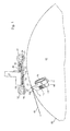
- the opening 07 leads to a running along the cylinder 02 channel 08, in which a holding device, for. B. is a clamping device, the z. B. essentially from a in the base 09 of the channel 08 in a groove 11 pivotally mounted holding means 12 and one between a wall 13 of the channel 08 and the holding means 12th clamped spring element 14 is made (Fig. 1).
- the holding means 12 thus has an operating position a holding position, in particular a clamping position and a release position.
- a Such clamping device is z. As described in DE 100 58 996 C1. to Explanation of further details of the clamping device and its operation will be expressly referred to the aforementioned document.
- a holder 21, z. B. is provided along the cylinder 02 extending traverse 21, wherein a Device for pressing an elevator 01 to the cylinder 02 of the printing press with Help of pressing elements 31; 32, preferably rolling elements 31; 32 at the Bracket 21 is arranged, wherein the rolling elements 31; 32 to the cylinder 02 on or are offset from this.
- a first carrier 22 with a first end 23 and a second end 24 and a second carrier 26 having a first end 27 and a second end 28 are provided, wherein in one embodiment, the first end 23 of the first carrier 22 with the along the cylinder 02 extending traverse 21 fixed connected is.
- At the second end 24 of the first carrier 22 is at least a first Rolling element 31 is arranged.
- the second end 28 of the second carrier 26 has at least one second rolling element 32 arranged.
- the first rolling element 31 and the second rolling element 32 are thus in Circumferentially arranged circumferentially of the cylinder 02 in a row, so that - As can be seen from the figures - a so-called double roller or Tandem roller arrangement results.
- tandem arrangement indicates that in the circumferential direction of the cylinder behind one another two substantially similar Components, here pressing elements or rolling elements are arranged.
- a first acting on the first carrier 22 actuating means 33 and a second on the second carrier 26 acting adjusting means 34 is provided, wherein the first adjusting means 33 and the second adjusting means 34 are independently operable.
- Such reached independent arrival and Ab monkeit the rolling elements 31; 32 is just then an advantage if several elevators 01 side by side on the cylinder 02 in the axial direction are arranged and individual lifts 01 selectively to be clamped or unclamped. So z. B.
- the adjusting means 33; 34 are z. B. as a acted upon by a pressure medium, reversible deformable hollow body, z. B. as a hose 33; 34, executed.
- the first on the first carrier 22 acting adjusting means 33 may, for. B. against a fixed to the crossbeam Supported 21 or molded there rigid stop 29, because the first Adjusting means 33 in particular between the traverse 21 and the stop 29 and the the first carrier 22 is arranged, whereas the second on the second carrier 26 acting adjusting means 34 preferably between the first carrier 22 and the second Carrier 26 is arranged and preferably at the with the crossbar 21st connected first end 23 of the first carrier 22 is supported.
- the second carrier 26 it is beneficial to the second carrier 26 to perform longer than the first carrier 22, with such a large supernatant, that at the second end 28 of the second carrier 26 arranged second rolling element 32 in the unactuated state of the second actuating means 34 laterally next to the traverse 21 is positionable, but preferably without the traverse 21 too touch.
- the carrier 22; 26 each as an elastically bendable, d. H. reversible form deformable body, in particular in leaf-shaped, z. B. as a Spring plate 22; 26.
- a carrier 22; 26 by an operation of an associated Adjusting means 33; 34 can be bent elastically to a rolling element 31; 32 at the To turn on cylinder 02, no additional means are required to attach to the straps 22; 26 arranged rolling elements 31; 32 after an actuation of the associated Adjusting means 33; 34 again turn off the cylinder 02.
- Spring in this version the carriers 22; 26 without the involvement of outside attacking forces in their original Position back.
- the rolling elements 31; 32 may be used as a roller 31; 32 or a roller 31; 32 be educated. Also, on the cross member 21 next to each other a plurality of first carrier 22 may each be arranged with at least one first rolling element 31, wherein these Rolling elements 31 independently of each other individually or in groups by their carriers 22 associated first adjusting means 33 to the cylinder 02 on or are off. As well It may be advantageous, on the first carrier 22 side by side a plurality of second carrier 26 each with at least one second rolling element 32 to be arranged, this Rolling elements 32 independently of each other individually or in groups by their carriers 26 associated second adjusting means 34 to the cylinder 02 on or are off.
- a preferred embodiment provides that on the first carrier 22 a along the cylinder 02 extending roller 31 and a plurality of second carrier 26 with at least one roller 32nd are arranged. This version is particularly useful when the Cylinder 02 side by side several elevators 01 and each elevator 01 a second carrier 26 is associated with at least one second rolling element 32.
- the device for pressing a Elevator 01 to a cylinder 02 of a printing press with the aid of pressing elements 31; 32 be designed such that several on the cylinder 02 in the axial direction Lifts 01 are arranged side by side, with an elevator associated with 01 Pressing elements 31; 32 independently assigned to another elevator 01 Pressing elements 31; 32 to the cylinder 02 on or are offset from this, wherein this device is characterized in that the pressing elements 31; 32 as Rolling elements, in particular as rollers 31; 32 are formed.
- the can Pressing elements 31; 32 or rolling elements 31; 32 during the rotation of the cylinder 02 be employed at least temporarily.
- the device for pressing a Elevator 01 to a cylinder 02 of a printing machine by means of rolling elements 31; 32 has in the axial direction of the cylinder 02 both a plurality of first rolling elements 31 as Also, a plurality of second rolling elements 32, wherein in the circumferential direction of the cylinder 02nd the second rolling elements 32 spaced from the first rolling elements 31 are. It is characterized by the fact that single or groups of second Rolling elements 32 independent of individual or groups of first rolling elements 31 can be adjusted to the cylinder 02 or offset from this. But it can also all first rolling elements 31 are turned on and the second rolling elements 32 partially or parked.
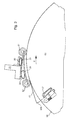
- the cylinder 02 is rotated so far in its production direction P until the Suspension leg 03b at the trailing end of the elevator 01 on the second wall 17 of the same or an identical, on the circumference of the cylinder 02 to the first Opening 07 staggered second opening 07 is present, wherein the rolling elements 32 press the elevator 01 to the lateral surface 06 of the cylinder 02.
- the rolling element 32 closest to the trailing end of the elevator 01 pushes the suspension leg 03b in the opening 07 and the elevator 01 holding Holding means 12 changes from its release position to its holding position.
- the rolling elements 31; 32 are connected to one or more on the lateral surface 06 of the Cylinders 02 mounted elevators 01 employed.
- the cylinder 02 rotates until the arranged on the second carrier 26 rolling element 32nd on suspension leg 03b of the trailing end of a lift 01 to be tensioned pending.
- the suspension leg 03b of the trailing end of the elevator to be tensioned 01 upcoming rolling element 32 is turned off by the cylinder 02 and the holding means 12th the holding device preferably changes by pivoting into its release position, whereupon the suspension leg 03b at the trailing end of the Homelandspannenden Elevator 01 automatically springs out of the opening 07 due to its residual stress, while the suspension leg 03b at the trailing end further on the cylinder 02 On-lying elevators 01 due to the rolling elements 32 pressing on them at the second Wall 17 of the opening 07 remain applied.
- the holding means 12 of the holding device preferably changes again into its Hold position and the cylinder 02 rotates so far counter to its production direction P, to the suspension leg 03a at the leading end of the elevator to be tensioned 01 of the first wall 04 of the opening 07 aushssenbar and thus removable from the cylinder 02 is.
- the rolling elements 31; 32 are of all on the lateral surface 06 of the cylinder 02nd resting elevators 01 parked.
- the cylinder 02 rotates until the arranged on the second carrier 26 rolling element 32nd is above the suspension leg 03b at the trailing end of the elevators 01, d. H. yourself Although still out of contact, but still in their immediate vicinity.
- the holding means 12 of the holding device preferably changes by pivoting in his Release position, whereupon the suspension leg 03b at the trailing end of all Lifts 01 automatically springs out of the opening 07 by residual stress.
- the elevators 01 remain due to the on the Cylinder 02 employed rolling elements 31 fixed on the lateral surface 06 of the cylinder 02.
- the holding means 12 of the holding device changes back to its holding position and all rolling elements 31; 32 are turned off by the cylinder 02.
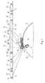
- FIG. 7 shows an association of arranged on a plurality of second carriers 26 Rolling elements 32 applied to a plurality of side by side on a cylinder 02 Lifts 01 during the unwinding of one of these elevators 01.
- three rolling elements 32 are assigned to one elevator 01.
- These rolling elements 32nd can independently of the other rolling elements 31; 32 from the cylinder 02 on or be turned off while z. B. adjacent elevators 01 to the lateral surface 06 of the Cylinder 02 are pressed.
- the rolling element 31 is here a continuous roller 31, whereas the rolling elements 32 consists of a plurality of individual rollers 32.
- the Rolling elements 31; 32 are spaced apart in the circumferential direction of the cylinder 02 arranged.
- the roller 31 is juxtaposed with all on the cylinder 02 lying lifts 01 in contact while the trailing end of the to be peeled elevator 01 is released.
- the rolling elements 31; 32 preferably with pneumatically actuable adjusting means 33; 34 on or off the cylinder 02.
- the rolling elements 31; 32 are at all on the lateral surface 06 of the cylinder 02 on elevators 01 employed.
- the cylinder 02 rotates until the arranged on the second carrier 26 Rolling element 32 above the opening 07 at the trailing end of a to be tamped Elevator 01 is located.
- the holding means 12 of the holding device changes to its release position.
- the suspension leg 03b of remaining elevators 01 remain in the opening 07, because the ends of these elevators 01 by assigned to them first rolling element 31 on the lateral surface 06 of the cylinder 02nd stay pressed.
- the length of the dissolved end of the cylinder 02 to removing elevator 01 is defined by the distance of the contact point of the first Rolling element 31 on the cylinder 02 determined by the opening 07.
- the holding means 12 of the holding device changes to its holding position and all Rolling elements 31; 32 or at least the first front in the direction of production P.
- Rolling elements 31 can be turned off by the cylinder 02. Thereafter, if necessary after a rotation of the cylinder 02 against its direction of production P of the to be tensioned elevator 01 from the outer surface 06 of the cylinder 02 removable.
- a method for pressing a flexible elevator 01 to a cylinder 02 of a Printing machine with the aid of rolling elements 31; 32, wherein a first rolling element 31 and a second rolling element 32 is provided and both rolling elements 31; 32 in Circumferentially arranged circumferentially of the cylinder 02 from each other, wherein on the cylinder 02 in the axial direction a plurality of elevators 01 are arranged side by side, can also be characterized in that the rolling elements 31; 32 individually or in Groups to the elevators 01 resting on the lateral surface 06 of the cylinder 02 or be turned off by these.
- the trailing in the direction of production P of the cylinder 02 arranged on the to be pressed elevator 01 employed pressing member 32 is preferably then from Cylinder 02 turned off when this pressing element 32 due to a rotational movement of the cylinder 02 on an introduced into the cylinder 02 opening 07 or near this Opening 07 is located and a suspension leg 03b on in the production direction P the cylinder 02 trailing end of the elevator 01 in this opening 07 holding Holding means 12 has changed from its holding position to its release position.
- this suspension leg 03b can preferably automatically from the Release opening 07.
- the further in the direction of production P of the cylinder 02 leading arranged pressing element 31 preferably remains as long as to be pressed Lift 01 employed until this Andrückelement 31 as a result of against his Production direction P directed rotational movement of the cylinder 02 on a in the Cylinder 02 introduced opening 07 or near this opening 07 is located, with a Suspension leg 03a at the leading in the direction of production P of the cylinder 02 end the elevator 01 is held in this opening 07.
- the elevator 01 remains accordingly the salaried, leading in the direction of production P of the cylinder 02 arranged Pressing element 31 fixed on the cylinder 02 until the suspension leg 03a on in Production direction P of the cylinder 02 leading end of the elevator 01 from the Opening 07 is removable.
- a method for pressing an elevator 01 to a cylinder 02 of a Printing machine in which on the cylinder 02 in the axial direction more Lifts 01 can be arranged next to each other, can provide that at least one on the cylinder 02 mecanical elevator 01 pressing rolling element 32 to Start of Aufspannvorgangs employed on the cylinder 02 and only at the end of the Clamping process is turned off again by the cylinder 02.
- These are preferably Elevators 01 with angled hangers 03a; 03b at their ends to the Hooking in an introduced into the cylinder 02, preferably slit-shaped Opening 07 used.
- the rolling element 32 associated with the elevator 01 to be tensioned becomes regardless of a different roller 01 associated with rolling element 32 to the Cylinder 02 employed or parked by the cylinder 02.
- the elevators 01 assigned Rolling elements 32 arranged. It can be provided that at the beginning of the Aufspannvorgangs only that the réellespannenden elevator 01 associated rolling element 32 is hired.
Landscapes
- Rolls And Other Rotary Bodies (AREA)
- Rotary Presses (AREA)
- Inking, Control Or Cleaning Of Printing Machines (AREA)
- Supply, Installation And Extraction Of Printed Sheets Or Plates (AREA)
- Folding Of Thin Sheet-Like Materials, Special Discharging Devices, And Others (AREA)
Abstract
Description
- Fig. 1
- eine Vorrichtung zum Andrücken eines Aufzugs an einen Zylinder einer Druckmaschine mit Hilfe von Wälzelementen;
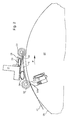
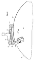
- Fig. 2 bis Fig. 4
- einen Ablauf eines Verfahrens zum Aufspannen eines biegsamen Aufzugs auf einen Zylinder einer Druckmaschine mit Hilfe von an elastisch biegbaren Trägern angeordneten Wälzelementen;
- Fig. 5 und 6
- einen Verfahrensschritt beim Abspannen eines biegsamen Aufzugs von einem Zylinder einer Druckmaschine mit Hilfe von an elastisch biegbaren Trägern angeordneten Wälzelementen;
- Fig. 7
- eine Zuordnung von an zweiten Trägern angeordneten Wälzelementen zu mehreren nebeneinander auf einem Zylinder aufgebrachten Aufzügen während des Abspannens von einem dieser Aufzüge.
- 01
- Aufzug; Druckform
- 02
- Zylinder; Formzylinder
- 03a; 03b
- Einhängeschenkel
- 04
- Wandung, erste
- 05
- -
- 06
- Mantelfläche
- 07
- Öffnung
- 08
- Kanal
- 09
- Grund
- 10
- -
- 11
- Nut
- 12
- Haltemittel, Hebel
- 13
- Wandung (08)
- 14
- Federelement
- 15
- -
- 16
- Stellmittel
- 17
- Wandung, zweite
- 18
- -
- 19
- -
- 20
- -
- 21
- Halterung; Traverse
- 22
- Träger, erster; Federblech
- 23
- Ende, erstes (22)
- 24
- Ende, zweites (22)
- 25
- -
- 26
- Träger, zweiter; Federblech
- 27
- Ende, erstes (26)
- 28
- Ende, zweites (26)
- 29
- Anschlag
- 30
- -
- 31
- Wälzelement, erstes; Andrückelement; Rolle; Walze
- 32
- Wälzelement, zweites; Andrückelement; Rolle; Walze
- 33
- Stellmittel, erstes; Schlauch
- 34
- Stellmittel, zweites; Schlauch
- 35
- -
- P
- Produktionsrichtung
Claims (7)
- Verfahren zum Andrücken eines Aufzugs (01) an einen Zylinder (02) einer Druckmaschine, wobei ein den auf dem Zylinder (02) aufzuspannenden Aufzug (01) andrückendes Wälzelement (32) zu Beginn des Aufspannvorgangs an den Zylinder (02) angestellt und erst am Ende des Aufspannvorgangs wieder vom Zylinder (02) abgestellt wird, wobei auf dem Zylinder (02) mehrere Aufzüge (01) anordenbar sind, wobei das dem aufzuspannenden Aufzug (01) zugeordnete Wälzelement (32) unabhängig von einem einem anderen Aufzug (01) zugeordneten Wälzelement (32) an den Zylinder (02) angestellt bzw. vom Zylinder (02) abgestellt wird, dadurch gekennzeichnet, dass auf dem Zylinder (02) in dessen axialer Richtung mehrere Aufzüge (01) nebeneinander anordenbar sind, wobei in axialer Richtung des Zylinders (02) nebeneinander angeordnete, den Aufzügen (01) zugeordnete Wälzelemente (32) verwendet werden und wobei zu Beginn des Aufspannvorgangs nur das dem aufzuspannenden Aufzug (01) zugeordnete Wälzelement (32) angestellt wird.
- Verfahren nach Anspruch 1, dadurch gekennzeichnet, dass Aufzüge (01) mit Einhängeschenkeln (03a; 03b) an ihren Enden zum Einhängen in einer in den Zylinder (02) eingebrachten Öffnung (07) verwendet werden.
- Verfahren nach Anspruch 2, dadurch gekennzeichnet, dass zu Beginn des Aufspannvorgangs der Einhängeschenkel (03a) am in Produktionsrichtung (P) des Zylinders (02) vorlaufenden Ende des Aufzugs (01) in die Öffnung (07) eingehängt wird.
- Verfahren nach Anspruch 2, dadurch gekennzeichnet, dass am Ende des Aufspannvorgangs der Einhängeschenkel (03b) am in Produktionsrichtung (P) des Zylinders (02) nachlaufenden Ende in die Öffnung (07) eingehängt wird.
- Verfahren nach Anspruch 4, dadurch gekennzeichnet, dass ein den Einhängeschenkel (03b) am in Produktionsrichtung (P) des Zylinders (02) nachlaufenden Ende haltendes Haltemittel (12) von einer Freigabeposition in eine Halteposition wechselt.
- Verfahren nach Anspruch 5, dadurch gekennzeichnet, dass das Wälzelement (32) nach dem Wechsel des Haltemittels (12) von seiner Freigabeposition in seine Halteposition vom Zylinder (02) abgestellt wird.
- Verfahren nach Anspruch 2, dadurch gekennzeichnet, dass nach dem Einhängen des Einhängeschenkels (03a) am in Produktionsrichtung (P) des Zylinders (02) vorlaufenden Ende der Zylinder (02) in dessen Produktionsrichtung (P) gedreht wird, bis der Einhängeschenkel (03b) am in Produktionsrichtung (P) des Zylinders (02) nachlaufenden Ende einhängbar ist.
Applications Claiming Priority (3)
| Application Number | Priority Date | Filing Date | Title |
|---|---|---|---|
| DE10238177A DE10238177B3 (de) | 2002-08-21 | 2002-08-21 | Vorrichtung zum Andrücken eines Aufzugs an einen Zylinder einer Druckmaschine mit Hilfe von in Umfangsrichtung des Zylinders voneinander beabstandeten ersten und zweiten Wälzelementen |
| DE10238177 | 2002-08-21 | ||
| EP03790689A EP1530513B1 (de) | 2002-08-21 | 2003-08-07 | Vorrichtung und verfahren zum andrücken eines aufzugs an einen zylinder einer druckmaschine mit hilfe von andrückelementen |
Related Parent Applications (1)
| Application Number | Title | Priority Date | Filing Date |
|---|---|---|---|
| EP03790689A Division EP1530513B1 (de) | 2002-08-21 | 2003-08-07 | Vorrichtung und verfahren zum andrücken eines aufzugs an einen zylinder einer druckmaschine mit hilfe von andrückelementen |
Publications (3)
| Publication Number | Publication Date |
|---|---|
| EP1535735A2 true EP1535735A2 (de) | 2005-06-01 |
| EP1535735A3 EP1535735A3 (de) | 2006-05-31 |
| EP1535735B1 EP1535735B1 (de) | 2006-09-20 |
Family
ID=30010620
Family Applications (6)
| Application Number | Title | Priority Date | Filing Date |
|---|---|---|---|
| EP05100934A Expired - Lifetime EP1535735B1 (de) | 2002-08-21 | 2003-08-07 | Verfahren zum Andrücken eines Aufzugs an einen Zylinder einer Druckmaschine |
| EP03790688A Expired - Lifetime EP1530516B1 (de) | 2002-08-21 | 2003-08-07 | Vorrichtungen zum andrücken eines aufzugs an einen zylinder einer druckmaschine |
| EP05100932A Expired - Lifetime EP1535734B1 (de) | 2002-08-21 | 2003-08-07 | Verfahren zum Andrücken eines Aufzugs an einen Zylinder einer Druckmaschine mit Hilfe von Andrückelementen |
| EP03790689A Expired - Lifetime EP1530513B1 (de) | 2002-08-21 | 2003-08-07 | Vorrichtung und verfahren zum andrücken eines aufzugs an einen zylinder einer druckmaschine mit hilfe von andrückelementen |
| EP05100974A Withdrawn EP1543968A3 (de) | 2002-08-21 | 2003-08-07 | Vorrichtungen zum Andrücken eines Aufzugs an einen Zylinder einer Druckmaschine |
| EP05100973A Withdrawn EP1543967A3 (de) | 2002-08-21 | 2003-08-07 | Verfahren zum Aufspannen eines Aufzugs auf einen Zylinder und Verfahren zum Abspannen eines Aufzugs von einem Zylinder einer Druckmaschine |
Family Applications After (5)
| Application Number | Title | Priority Date | Filing Date |
|---|---|---|---|
| EP03790688A Expired - Lifetime EP1530516B1 (de) | 2002-08-21 | 2003-08-07 | Vorrichtungen zum andrücken eines aufzugs an einen zylinder einer druckmaschine |
| EP05100932A Expired - Lifetime EP1535734B1 (de) | 2002-08-21 | 2003-08-07 | Verfahren zum Andrücken eines Aufzugs an einen Zylinder einer Druckmaschine mit Hilfe von Andrückelementen |
| EP03790689A Expired - Lifetime EP1530513B1 (de) | 2002-08-21 | 2003-08-07 | Vorrichtung und verfahren zum andrücken eines aufzugs an einen zylinder einer druckmaschine mit hilfe von andrückelementen |
| EP05100974A Withdrawn EP1543968A3 (de) | 2002-08-21 | 2003-08-07 | Vorrichtungen zum Andrücken eines Aufzugs an einen Zylinder einer Druckmaschine |
| EP05100973A Withdrawn EP1543967A3 (de) | 2002-08-21 | 2003-08-07 | Verfahren zum Aufspannen eines Aufzugs auf einen Zylinder und Verfahren zum Abspannen eines Aufzugs von einem Zylinder einer Druckmaschine |
Country Status (8)
| Country | Link |
|---|---|
| US (2) | US7237484B2 (de) |
| EP (6) | EP1535735B1 (de) |
| CN (1) | CN1328047C (de) |
| AT (4) | ATE452026T1 (de) |
| AU (2) | AU2003266108A1 (de) |
| DE (5) | DE10238177B3 (de) |
| ES (2) | ES2270404T3 (de) |
| WO (2) | WO2004020205A2 (de) |
Cited By (1)
| Publication number | Priority date | Publication date | Assignee | Title |
|---|---|---|---|---|
| EP2036728A3 (de) * | 2007-09-13 | 2010-11-10 | Koenig & Bauer Aktiengesellschaft | Rotationsdruckmaschine mit mindestens einer Störschall emittierenden Druckeinheit |
Families Citing this family (6)
| Publication number | Priority date | Publication date | Assignee | Title |
|---|---|---|---|---|
| DE102004059338B3 (de) | 2004-08-16 | 2005-12-22 | Koenig & Bauer Ag | Verfahren und Vorrichtung zum Abspannen mindestens eines Aufzugs von einem Zylinder einer Druckmaschine |
| DE102005017182A1 (de) | 2005-04-13 | 2006-10-19 | Man Roland Druckmaschinen Ag | Vorrichtung und Verfahren zum Andrücken einer Bespannung an einen Druckwerkzylinder einer Rotationsdruckmaschine |
| DE102006059772A1 (de) * | 2006-12-15 | 2008-06-19 | Man Roland Druckmaschinen Ag | Vorrichtung zur Durchführung eines Druckplattenwechsels an einem Formzylinder einer Druckmaschine |
| DE102007000639B3 (de) * | 2007-03-02 | 2008-08-07 | Koenig & Bauer Aktiengesellschaft | Vorrichtung mit mehreren selektiv betätigbaren Funktionseinheiten |
| DK2844471T3 (en) * | 2012-04-24 | 2018-10-22 | Tresu As | Pressure works with adjustment of rollers by a deflector and method of adjustment |
| DE102015210819A1 (de) | 2015-06-12 | 2016-12-15 | Koenig & Bauer Ag | Vorrichtung zum Auflegen zumindest eines Aufzugs auf eine Mantelfläche eines Zylinders einer Druckmaschine und ein Verfahren zum Auflegen zumindest eines Aufzugs auf eine Mantelfläche eines Zylinders einer Druckmaschine |
Citations (8)
| Publication number | Priority date | Publication date | Assignee | Title |
|---|---|---|---|---|
| US4727807A (en) | 1985-09-30 | 1988-03-01 | Tokyo Kikai Seisakusho | Apparatus for automatically mounting and removing printing plates in rotary printing press |
| US5406888A (en) | 1989-12-06 | 1995-04-18 | Komori Corporation | Automatic plate replacing apparatus for printing press |
| EP0712725A2 (de) | 1994-11-10 | 1996-05-22 | M.A.N.-ROLAND Druckmaschinen Aktiengesellschaft | Wälzelement zum Andrücken einer flexiblen Druckplatte an den Formzylinder |
| DE19639800C1 (de) | 1996-09-27 | 1998-02-05 | Kba Planeta Ag | Vorrichtung zum Positionieren des freien Endes einer Druckplatte |
| DE19719559A1 (de) | 1997-05-09 | 1998-11-12 | Koenig & Bauer Albert Ag | Verfahren und Vorrichtung zur Montage biegsamer Druckplatten |
| WO2001087613A1 (de) | 2000-05-17 | 2001-11-22 | Koenig & Bauer Aktiengesellschaft | Verfahren und vorrichtungen zum andrücken eines aufzuges auf einen zylinder |
| DE10120134A1 (de) | 2000-05-17 | 2001-11-22 | Heidelberger Druckmasch Ag | Druckmaschine mit Mehrplatten-Plattenzylinder |
| DE10058996C1 (de) | 2000-11-28 | 2002-06-13 | Koenig & Bauer Ag | Vorrichtung zur Befestigung eines Aufzuges |
Family Cites Families (7)
| Publication number | Priority date | Publication date | Assignee | Title |
|---|---|---|---|---|
| US540600A (en) * | 1895-06-04 | Sash-pulley | ||
| DE4414443C1 (de) * | 1994-04-26 | 1995-11-30 | Heidelberger Druckmasch Ag | Vorrichtung zum Führen eines Druckträgers |
| DE19620997C2 (de) | 1996-05-24 | 1998-03-26 | Koenig & Bauer Albert Ag | Verfahren und Vorrichtung zum axialen Positionieren einer Druckplatte |
| US6792860B2 (en) | 2000-05-17 | 2004-09-21 | Koenig & Bauer Aktiengesellschaft | Method and device for pressing a packing against a cylinder |
| ATE475536T1 (de) * | 2001-10-05 | 2010-08-15 | Koenig & Bauer Ag | Druckeinheit und eine rollenrotationsdruckmaschine |
| EP1453678B1 (de) * | 2001-11-28 | 2005-04-20 | Koenig & Bauer Aktiengesellschaft | Vorrichtungen und verfahren zum ausrichten oder montieren eines an einen zylinder einer druckmaschine herangeführten aufzugs |
| DE10158158A1 (de) * | 2001-11-28 | 2003-06-18 | Koenig & Bauer Ag | Vorrichtung zum Aufziehen eines Aufzuges |
-
2002
- 2002-08-21 DE DE10238177A patent/DE10238177B3/de not_active Expired - Fee Related
-
2003
- 2003-08-07 EP EP05100934A patent/EP1535735B1/de not_active Expired - Lifetime
- 2003-08-07 EP EP03790688A patent/EP1530516B1/de not_active Expired - Lifetime
- 2003-08-07 US US10/524,878 patent/US7237484B2/en not_active Expired - Fee Related
- 2003-08-07 WO PCT/DE2003/002650 patent/WO2004020205A2/de not_active Ceased
- 2003-08-07 AT AT05100932T patent/ATE452026T1/de not_active IP Right Cessation
- 2003-08-07 AT AT05100934T patent/ATE340078T1/de not_active IP Right Cessation
- 2003-08-07 EP EP05100932A patent/EP1535734B1/de not_active Expired - Lifetime
- 2003-08-07 ES ES05100934T patent/ES2270404T3/es not_active Expired - Lifetime
- 2003-08-07 EP EP03790689A patent/EP1530513B1/de not_active Expired - Lifetime
- 2003-08-07 AT AT03790688T patent/ATE448083T1/de not_active IP Right Cessation
- 2003-08-07 WO PCT/DE2003/002651 patent/WO2004020198A2/de not_active Ceased
- 2003-08-07 EP EP05100974A patent/EP1543968A3/de not_active Withdrawn
- 2003-08-07 DE DE50306205T patent/DE50306205D1/de not_active Expired - Lifetime
- 2003-08-07 EP EP05100973A patent/EP1543967A3/de not_active Withdrawn
- 2003-08-07 AT AT03790689T patent/ATE350218T1/de not_active IP Right Cessation
- 2003-08-07 DE DE50312116T patent/DE50312116D1/de not_active Expired - Lifetime
- 2003-08-07 AU AU2003266108A patent/AU2003266108A1/en not_active Abandoned
- 2003-08-07 ES ES03790689T patent/ES2277140T3/es not_active Expired - Lifetime
- 2003-08-07 DE DE50312245T patent/DE50312245D1/de not_active Expired - Lifetime
- 2003-08-07 AU AU2003266109A patent/AU2003266109A1/en not_active Abandoned
- 2003-08-07 CN CNB038195771A patent/CN1328047C/zh not_active Expired - Fee Related
- 2003-08-07 DE DE50305132T patent/DE50305132D1/de not_active Expired - Lifetime
- 2003-08-07 US US10/525,018 patent/US7240616B2/en not_active Expired - Fee Related
Patent Citations (8)
| Publication number | Priority date | Publication date | Assignee | Title |
|---|---|---|---|---|
| US4727807A (en) | 1985-09-30 | 1988-03-01 | Tokyo Kikai Seisakusho | Apparatus for automatically mounting and removing printing plates in rotary printing press |
| US5406888A (en) | 1989-12-06 | 1995-04-18 | Komori Corporation | Automatic plate replacing apparatus for printing press |
| EP0712725A2 (de) | 1994-11-10 | 1996-05-22 | M.A.N.-ROLAND Druckmaschinen Aktiengesellschaft | Wälzelement zum Andrücken einer flexiblen Druckplatte an den Formzylinder |
| DE19639800C1 (de) | 1996-09-27 | 1998-02-05 | Kba Planeta Ag | Vorrichtung zum Positionieren des freien Endes einer Druckplatte |
| DE19719559A1 (de) | 1997-05-09 | 1998-11-12 | Koenig & Bauer Albert Ag | Verfahren und Vorrichtung zur Montage biegsamer Druckplatten |
| WO2001087613A1 (de) | 2000-05-17 | 2001-11-22 | Koenig & Bauer Aktiengesellschaft | Verfahren und vorrichtungen zum andrücken eines aufzuges auf einen zylinder |
| DE10120134A1 (de) | 2000-05-17 | 2001-11-22 | Heidelberger Druckmasch Ag | Druckmaschine mit Mehrplatten-Plattenzylinder |
| DE10058996C1 (de) | 2000-11-28 | 2002-06-13 | Koenig & Bauer Ag | Vorrichtung zur Befestigung eines Aufzuges |
Cited By (1)
| Publication number | Priority date | Publication date | Assignee | Title |
|---|---|---|---|---|
| EP2036728A3 (de) * | 2007-09-13 | 2010-11-10 | Koenig & Bauer Aktiengesellschaft | Rotationsdruckmaschine mit mindestens einer Störschall emittierenden Druckeinheit |
Also Published As
Similar Documents
| Publication | Publication Date | Title |
|---|---|---|
| EP0660778B1 (de) | Verfahren und einrichtung zum abführen von druckplatten | |
| EP0678382A1 (de) | Vorrichtung zum Austausch von Druckformen an Rotationsdruckmaschinen | |
| DE102007030174B3 (de) | Verfahren zum Montieren einer biegsamen Druckform auf einem Formzylinder einer Rotationsdruckmaschine | |
| EP0606604B1 (de) | Vorrichtung zum Aufspannen von biegsamen Druckplatten auf einen Formzylinder einer Druckmaschine | |
| EP1535734B1 (de) | Verfahren zum Andrücken eines Aufzugs an einen Zylinder einer Druckmaschine mit Hilfe von Andrückelementen | |
| EP1530515B1 (de) | Verfahren zum wechseln mindestens einer druckform und druckmaschine mit mehreren formzylindern | |
| EP1530514B1 (de) | Verfahren zum montieren eines aufzugs auf einem zylinder einer druckmaschine | |
| EP1453678B1 (de) | Vorrichtungen und verfahren zum ausrichten oder montieren eines an einen zylinder einer druckmaschine herangeführten aufzugs | |
| DE102017207050A1 (de) | Druckwerk zum Bedrucken bogenförmigen Bedruckstoffs sowie Blechdruckmaschine mit einem derartigen Druckwerk | |
| DE102006050568B3 (de) | Vorrichtung zum Andrücken eines Aufzugs an einen Zylinder | |
| EP1531995B1 (de) | Vorrichtung zum führen eines aufzugs an einen zylinder einer druckmaschine | |
| EP3615338B1 (de) | Druckwerk zum bedrucken bogenförmigen bedruckstoffs, blechdruckmaschine mit einem derartigen druckwerk sowie verfahren zum aufziehen von aufzügen auf druckwerkzylindern eines druckwerks einer bogenverarbeitenden druckmaschine | |
| EP2644382B1 (de) | Anordnung aufweisend einen Formzylinder einer Druckmaschine, eine biegsame Druckplatte und ein Registerelement | |
| EP2644381B1 (de) | Verfahren zum formschlüssigen Verbinden einer biegsamen Druckform mit einem Registerelement und/oder zum Trennen einer solchen Verbindung | |
| EP2415604B1 (de) | Vorrichtung zum Abführen einer Druckform von einem Formzylinder einer Druckeinheit | |
| EP1531994B1 (de) | Verfahren und vorrichtung zum abnehmen eines aufzugs von einem zylinder einer druckmaschine | |
| EP1894721B1 (de) | Rotationsdruckmaschine mit einer vorrichtung zum montieren einer biegsamen druckform | |
| DE102020123196A1 (de) | Vorrichtung zum Spannen eines bogenförmigen Walzenbezugs um eine Walze | |
| EP1070584A1 (de) | Bogendruckmaschine | |
| DE102017207052A1 (de) | Vorrichtung zum Aufziehen eines Aufzuges auf einem Druckwerkszylinder eines Druckwerks und Vorrichtung zum Wechseln eines Aufzuges an einem Druckwerkzylinder | |
| DE10238124A1 (de) | Vorrichtungen zum Ausrichten eines an einen Zylinder einer Druckmaschine herangeführten Aufzugs und Verfahren zum Montieren eines solchen Aufzugs | |
| EP1900525A2 (de) | Vorrichtung zum Montieren einer Druckform auf einen Formzylinder einer Druckmaschine |
Legal Events
| Date | Code | Title | Description |
|---|---|---|---|
| PUAI | Public reference made under article 153(3) epc to a published international application that has entered the european phase |
Free format text: ORIGINAL CODE: 0009012 |
|
| AC | Divisional application: reference to earlier application |
Ref document number: 1530513 Country of ref document: EP Kind code of ref document: P |
|
| AK | Designated contracting states |
Kind code of ref document: A2 Designated state(s): AT BE BG CH CY CZ DE DK EE ES FI FR GB GR HU IE IT LI LU MC NL PT RO SE SI SK TR |
|
| AX | Request for extension of the european patent |
Extension state: AL LT LV MK |
|
| PUAL | Search report despatched |
Free format text: ORIGINAL CODE: 0009013 |
|
| AK | Designated contracting states |
Kind code of ref document: A3 Designated state(s): AT BE BG CH CY CZ DE DK EE ES FI FR GB GR HU IE IT LI LU MC NL PT RO SE SI SK TR |
|
| AX | Request for extension of the european patent |
Extension state: AL LT LV MK |
|
| 17P | Request for examination filed |
Effective date: 20060419 |
|
| GRAP | Despatch of communication of intention to grant a patent |
Free format text: ORIGINAL CODE: EPIDOSNIGR1 |
|
| GRAS | Grant fee paid |
Free format text: ORIGINAL CODE: EPIDOSNIGR3 |
|
| GRAA | (expected) grant |
Free format text: ORIGINAL CODE: 0009210 |
|
| AC | Divisional application: reference to earlier application |
Ref document number: 1530513 Country of ref document: EP Kind code of ref document: P |
|
| AK | Designated contracting states |
Kind code of ref document: B1 Designated state(s): AT BE BG CH CY CZ DE DK EE ES FI FR GB GR HU IE IT LI LU MC NL PT RO SE SI SK TR |
|
| PG25 | Lapsed in a contracting state [announced via postgrant information from national office to epo] |
Ref country code: IT Free format text: LAPSE BECAUSE OF FAILURE TO SUBMIT A TRANSLATION OF THE DESCRIPTION OR TO PAY THE FEE WITHIN THE PRESCRIBED TIME-LIMIT;WARNING: LAPSES OF ITALIAN PATENTS WITH EFFECTIVE DATE BEFORE 2007 MAY HAVE OCCURRED AT ANY TIME BEFORE 2007. THE CORRECT EFFECTIVE DATE MAY BE DIFFERENT FROM THE ONE RECORDED. Effective date: 20060920 Ref country code: SI Free format text: LAPSE BECAUSE OF FAILURE TO SUBMIT A TRANSLATION OF THE DESCRIPTION OR TO PAY THE FEE WITHIN THE PRESCRIBED TIME-LIMIT Effective date: 20060920 Ref country code: NL Free format text: LAPSE BECAUSE OF FAILURE TO SUBMIT A TRANSLATION OF THE DESCRIPTION OR TO PAY THE FEE WITHIN THE PRESCRIBED TIME-LIMIT Effective date: 20060920 Ref country code: CZ Free format text: LAPSE BECAUSE OF FAILURE TO SUBMIT A TRANSLATION OF THE DESCRIPTION OR TO PAY THE FEE WITHIN THE PRESCRIBED TIME-LIMIT Effective date: 20060920 Ref country code: IE Free format text: LAPSE BECAUSE OF FAILURE TO SUBMIT A TRANSLATION OF THE DESCRIPTION OR TO PAY THE FEE WITHIN THE PRESCRIBED TIME-LIMIT Effective date: 20060920 Ref country code: RO Free format text: LAPSE BECAUSE OF FAILURE TO SUBMIT A TRANSLATION OF THE DESCRIPTION OR TO PAY THE FEE WITHIN THE PRESCRIBED TIME-LIMIT Effective date: 20060920 Ref country code: SK Free format text: LAPSE BECAUSE OF FAILURE TO SUBMIT A TRANSLATION OF THE DESCRIPTION OR TO PAY THE FEE WITHIN THE PRESCRIBED TIME-LIMIT Effective date: 20060920 |
|
| REG | Reference to a national code |
Ref country code: GB Ref legal event code: FG4D Free format text: NOT ENGLISH |
|
| REG | Reference to a national code |
Ref country code: CH Ref legal event code: EP |
|
| GBT | Gb: translation of ep patent filed (gb section 77(6)(a)/1977) |
Effective date: 20061005 |
|
| REG | Reference to a national code |
Ref country code: IE Ref legal event code: FG4D Free format text: LANGUAGE OF EP DOCUMENT: GERMAN |
|
| REF | Corresponds to: |
Ref document number: 50305132 Country of ref document: DE Date of ref document: 20061102 Kind code of ref document: P |
|
| PG25 | Lapsed in a contracting state [announced via postgrant information from national office to epo] |
Ref country code: BG Free format text: LAPSE BECAUSE OF FAILURE TO SUBMIT A TRANSLATION OF THE DESCRIPTION OR TO PAY THE FEE WITHIN THE PRESCRIBED TIME-LIMIT Effective date: 20061220 Ref country code: SE Free format text: LAPSE BECAUSE OF FAILURE TO SUBMIT A TRANSLATION OF THE DESCRIPTION OR TO PAY THE FEE WITHIN THE PRESCRIBED TIME-LIMIT Effective date: 20061220 Ref country code: DK Free format text: LAPSE BECAUSE OF FAILURE TO SUBMIT A TRANSLATION OF THE DESCRIPTION OR TO PAY THE FEE WITHIN THE PRESCRIBED TIME-LIMIT Effective date: 20061220 |
|
| AKX | Designation fees paid |
Designated state(s): AT BE BG CH CY CZ DE DK EE ES FI FR GB GR HU IE IT LI LU MC NL PT RO SE SI SK TR |
|
| NLV1 | Nl: lapsed or annulled due to failure to fulfill the requirements of art. 29p and 29m of the patents act | ||
| PG25 | Lapsed in a contracting state [announced via postgrant information from national office to epo] |
Ref country code: PT Free format text: LAPSE BECAUSE OF FAILURE TO SUBMIT A TRANSLATION OF THE DESCRIPTION OR TO PAY THE FEE WITHIN THE PRESCRIBED TIME-LIMIT Effective date: 20070312 |
|
| ET | Fr: translation filed | ||
| REG | Reference to a national code |
Ref country code: ES Ref legal event code: FG2A Ref document number: 2270404 Country of ref document: ES Kind code of ref document: T3 |
|
| REG | Reference to a national code |
Ref country code: IE Ref legal event code: FD4D |
|
| PLBE | No opposition filed within time limit |
Free format text: ORIGINAL CODE: 0009261 |
|
| STAA | Information on the status of an ep patent application or granted ep patent |
Free format text: STATUS: NO OPPOSITION FILED WITHIN TIME LIMIT |
|
| 26N | No opposition filed |
Effective date: 20070621 |
|
| BERE | Be: lapsed |
Owner name: KOENIG & BAUER A.G. Effective date: 20070831 |
|
| PG25 | Lapsed in a contracting state [announced via postgrant information from national office to epo] |
Ref country code: GR Free format text: LAPSE BECAUSE OF FAILURE TO SUBMIT A TRANSLATION OF THE DESCRIPTION OR TO PAY THE FEE WITHIN THE PRESCRIBED TIME-LIMIT Effective date: 20061221 Ref country code: MC Free format text: LAPSE BECAUSE OF NON-PAYMENT OF DUE FEES Effective date: 20070831 |
|
| PG25 | Lapsed in a contracting state [announced via postgrant information from national office to epo] |
Ref country code: EE Free format text: LAPSE BECAUSE OF FAILURE TO SUBMIT A TRANSLATION OF THE DESCRIPTION OR TO PAY THE FEE WITHIN THE PRESCRIBED TIME-LIMIT Effective date: 20060920 |
|
| PG25 | Lapsed in a contracting state [announced via postgrant information from national office to epo] |
Ref country code: BE Free format text: LAPSE BECAUSE OF NON-PAYMENT OF DUE FEES Effective date: 20070831 |
|
| PGFP | Annual fee paid to national office [announced via postgrant information from national office to epo] |
Ref country code: ES Payment date: 20080820 Year of fee payment: 6 |
|
| PG25 | Lapsed in a contracting state [announced via postgrant information from national office to epo] |
Ref country code: AT Free format text: LAPSE BECAUSE OF NON-PAYMENT OF DUE FEES Effective date: 20070807 |
|
| PGFP | Annual fee paid to national office [announced via postgrant information from national office to epo] |
Ref country code: IT Payment date: 20080826 Year of fee payment: 6 |
|
| PG25 | Lapsed in a contracting state [announced via postgrant information from national office to epo] |
Ref country code: FI Free format text: LAPSE BECAUSE OF FAILURE TO SUBMIT A TRANSLATION OF THE DESCRIPTION OR TO PAY THE FEE WITHIN THE PRESCRIBED TIME-LIMIT Effective date: 20060920 Ref country code: CY Free format text: LAPSE BECAUSE OF FAILURE TO SUBMIT A TRANSLATION OF THE DESCRIPTION OR TO PAY THE FEE WITHIN THE PRESCRIBED TIME-LIMIT Effective date: 20060920 Ref country code: LU Free format text: LAPSE BECAUSE OF NON-PAYMENT OF DUE FEES Effective date: 20070807 |
|
| PG25 | Lapsed in a contracting state [announced via postgrant information from national office to epo] |
Ref country code: HU Free format text: LAPSE BECAUSE OF FAILURE TO SUBMIT A TRANSLATION OF THE DESCRIPTION OR TO PAY THE FEE WITHIN THE PRESCRIBED TIME-LIMIT Effective date: 20070321 Ref country code: TR Free format text: LAPSE BECAUSE OF FAILURE TO SUBMIT A TRANSLATION OF THE DESCRIPTION OR TO PAY THE FEE WITHIN THE PRESCRIBED TIME-LIMIT Effective date: 20060920 |
|
| REG | Reference to a national code |
Ref country code: ES Ref legal event code: FD2A Effective date: 20090808 |
|
| PG25 | Lapsed in a contracting state [announced via postgrant information from national office to epo] |
Ref country code: IT Free format text: LAPSE BECAUSE OF NON-PAYMENT OF DUE FEES Effective date: 20090807 |
|
| PG25 | Lapsed in a contracting state [announced via postgrant information from national office to epo] |
Ref country code: ES Free format text: LAPSE BECAUSE OF NON-PAYMENT OF DUE FEES Effective date: 20090808 |
|
| PGFP | Annual fee paid to national office [announced via postgrant information from national office to epo] |
Ref country code: CH Payment date: 20110822 Year of fee payment: 9 |
|
| REG | Reference to a national code |
Ref country code: CH Ref legal event code: PL |
|
| PG25 | Lapsed in a contracting state [announced via postgrant information from national office to epo] |
Ref country code: CH Free format text: LAPSE BECAUSE OF NON-PAYMENT OF DUE FEES Effective date: 20130831 Ref country code: LI Free format text: LAPSE BECAUSE OF NON-PAYMENT OF DUE FEES Effective date: 20130831 |
|
| REG | Reference to a national code |
Ref country code: FR Ref legal event code: PLFP Year of fee payment: 13 |
|
| REG | Reference to a national code |
Ref country code: DE Ref legal event code: R081 Ref document number: 50305132 Country of ref document: DE Owner name: KOENIG & BAUER AG, DE Free format text: FORMER OWNER: KOENIG & BAUER AKTIENGESELLSCHAFT, 97080 WUERZBURG, DE |
|
| PGFP | Annual fee paid to national office [announced via postgrant information from national office to epo] |
Ref country code: GB Payment date: 20150824 Year of fee payment: 13 Ref country code: DE Payment date: 20150918 Year of fee payment: 13 |
|
| PGFP | Annual fee paid to national office [announced via postgrant information from national office to epo] |
Ref country code: FR Payment date: 20150824 Year of fee payment: 13 |
|
| REG | Reference to a national code |
Ref country code: DE Ref legal event code: R119 Ref document number: 50305132 Country of ref document: DE |
|
| GBPC | Gb: european patent ceased through non-payment of renewal fee |
Effective date: 20160807 |
|
| REG | Reference to a national code |
Ref country code: FR Ref legal event code: ST Effective date: 20170428 |
|
| PG25 | Lapsed in a contracting state [announced via postgrant information from national office to epo] |
Ref country code: FR Free format text: LAPSE BECAUSE OF NON-PAYMENT OF DUE FEES Effective date: 20160831 Ref country code: DE Free format text: LAPSE BECAUSE OF NON-PAYMENT OF DUE FEES Effective date: 20170301 Ref country code: GB Free format text: LAPSE BECAUSE OF NON-PAYMENT OF DUE FEES Effective date: 20160807 |