EP1533806B1 - Verfahren und Vorrichtung zur Detektion von Medien - Google Patents
Verfahren und Vorrichtung zur Detektion von Medien Download PDFInfo
- Publication number
- EP1533806B1 EP1533806B1 EP04256486A EP04256486A EP1533806B1 EP 1533806 B1 EP1533806 B1 EP 1533806B1 EP 04256486 A EP04256486 A EP 04256486A EP 04256486 A EP04256486 A EP 04256486A EP 1533806 B1 EP1533806 B1 EP 1533806B1
- Authority
- EP
- European Patent Office
- Prior art keywords
- cartridge
- receiving chamber
- light
- data
- light source
- Prior art date
- Legal status (The legal status is an assumption and is not a legal conclusion. Google has not performed a legal analysis and makes no representation as to the accuracy of the status listed.)
- Expired - Lifetime
Links
- 238000000034 method Methods 0.000 title claims description 7
- 238000001514 detection method Methods 0.000 claims description 55
- 230000000903 blocking effect Effects 0.000 claims 3
- 230000000712 assembly Effects 0.000 description 2
- 238000000429 assembly Methods 0.000 description 2
- 238000013459 approach Methods 0.000 description 1
- 239000000463 material Substances 0.000 description 1
- 229910052751 metal Inorganic materials 0.000 description 1
- 239000002184 metal Substances 0.000 description 1
- 150000002739 metals Chemical class 0.000 description 1
- 238000012544 monitoring process Methods 0.000 description 1
- 229920003023 plastic Polymers 0.000 description 1
- 239000004033 plastic Substances 0.000 description 1
- 238000000926 separation method Methods 0.000 description 1
- 229910001220 stainless steel Inorganic materials 0.000 description 1
- 239000010935 stainless steel Substances 0.000 description 1
Images


Classifications
-
- G—PHYSICS
- G11—INFORMATION STORAGE
- G11B—INFORMATION STORAGE BASED ON RELATIVE MOVEMENT BETWEEN RECORD CARRIER AND TRANSDUCER
- G11B15/00—Driving, starting or stopping record carriers of filamentary or web form; Driving both such record carriers and heads; Guiding such record carriers or containers therefor; Control thereof; Control of operating function
- G11B15/675—Guiding containers, e.g. loading, ejecting cassettes
- G11B15/68—Automatic cassette changing arrangements; automatic tape changing arrangements
-
- G—PHYSICS
- G11—INFORMATION STORAGE
- G11B—INFORMATION STORAGE BASED ON RELATIVE MOVEMENT BETWEEN RECORD CARRIER AND TRANSDUCER
- G11B17/00—Guiding record carriers not specifically of filamentary or web form, or of supports therefor
- G11B17/22—Guiding record carriers not specifically of filamentary or web form, or of supports therefor from random access magazine of disc records
-
- G—PHYSICS
- G11—INFORMATION STORAGE
- G11B—INFORMATION STORAGE BASED ON RELATIVE MOVEMENT BETWEEN RECORD CARRIER AND TRANSDUCER
- G11B17/00—Guiding record carriers not specifically of filamentary or web form, or of supports therefor
- G11B17/22—Guiding record carriers not specifically of filamentary or web form, or of supports therefor from random access magazine of disc records
- G11B17/225—Guiding record carriers not specifically of filamentary or web form, or of supports therefor from random access magazine of disc records wherein the disks are transferred from a fixed magazine to a fixed playing unit using a moving carriage
Definitions
- the present invention generally pertains to media detection systems and in the preferred embodiments to media detection systems for cartridge-receiving devices.
- Media storage systems are well-known in the art and are commonly used to store data cartridges at known locations and to retrieve the desired data cartridges so that data may be written to and/or read from the data cartridges. Such media storage systems are often referred to as auto-changers or library storage systems.
- a typical auto-changer or media storage system may include one or more different types of cartridge receiving devices.
- one type of cartridge receiving device may comprise an individual cartridge storage location (e.g., for holding a single data cartridge) or a storage rack or "magazine" (e.g., for holding a plurality of data cartridges).
- Another type of cartridge-receiving device may comprise one or more cartridge read/write devices for reading data from and/or writing data to data cartridges.
- Yet another type of cartridge-receiving device is a cartridge-engaging assembly or "picker.” The cartridge-engaging assembly is provided for transporting the data cartridges in the media storage system (e.g., between the storage magazines and the read/write device).
- One way to determine whether a data cartridge is present in a cartridge-receiving device is by monitoring mechanical switches.
- a switch is thrown (e.g., turned “on” or “off") to indicate the presence or absence of the data cartridge.
- mechanical switches have finite tolerances; a smaller data cartridge may pass into or out of the cartridge receiving device undetected. This especially occurs if different sizes of data cartridges are to be used in the same media storage system.
- LTO linear tape open
- DLT digital linear tape
- EP-A-0 542 482 discloses a media detection system for detecting the presence of a data cartridge in a cartridge engaging system, the media detection system including:
- EP-A-1 426 946 published on 09.06.2004, which is relevant only to the novelty of the claimed invention discloses a media detection system for detecting data cartridge size in a cartridge engaging assembly, the media detection system including:
- the present invention seeks to provide improved media detection.
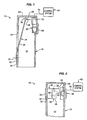
- a media detection system 10 is illustrated in Figures 1 and 2 as it may be used to detect the presence or absence of a data cartridge 12 (not shown in Figures 1 and 2 , but shown in Figures 5-8 ) within a cartridge receiving chamber 14 of a cartridge engaging assembly 16.
- the cartridge engaging assembly 16 may comprise a portion of a media storage system 18 ( Figure 4 ).
- the media-detection system 10 may also determine whether the data cartridge 12 comprises a narrow form-factor data cartridge 20 (shown in Figure 5 ) or a wide form-factor data cartridge 22 (shown in Figure 7 ).
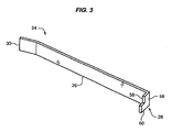
- the media-detection system 10 comprises a cartridge referencing member 24 having an arm portion 26 and a head portion 28.
- the distal end 30 of arm portion 26 is mounted to a sidewall 32 of the cartridge engaging assembly 16.
- this arrangement allows the head portion 28 of cartridge referencing member 24 to be displaced by a data cartridge 12, e.g., either a narrow form-factor data cartridge 20 ( Figure 5 ) or a wide form factor data cartridge 22 ( Figure 7 ).
- the media-detection system 10 also comprises a light source 34 and a detector assembly 36 operatively associated with the cartridge referencing member 24 so that the media-detection system 10 can detect the presence or absence of a data cartridge 12, as well as its relative size.
- the head portion 28 of cartridge referencing member 24 occludes or blocks certain amounts of light 38 produced by the light source 34, thereby preventing it from being reflected by the data cartridge 12 toward the detector assembly 36.
- the detector assembly 36 may comprise the same detector assembly that is used to read machine-readable code (e.g., a bar code) (not shown) provided on the data cartridge 12.
- the media detection system 10 may be utilized as follows to detect the presence or absence of a data cartridge 12 within the cartridge receiving chamber 14 of the cartridge engaging assembly 16. If no data cartridge 12 is present within the cartridge receiving chamber 14 of cartridge engaging assembly 16, the media detection system 10 is in a first configuration illustrated in Figures 1 and 2 . In the first configuration, the cartridge referencing member 24 is in a fully extended position and the head portion 28 substantially blocks all of the light 38 produced by the light source 34, thereby preventing the light from being detected by the detector assembly 36. A control system 40 operatively associated with the detector assembly 36 interprets the lack of light 38 reaching the detector assembly 36 as the absence of a data cartridge 12. Therefore, the control system 40 may operate the media storage system 18 in accordance with this configuration, i.e., the absence of a data cartridge 12 within the cartridge receiving chamber 14 of the cartridge engaging assembly 16.
- the media-detection system 10 is caused to be in a second configuration illustrated in Figures 5 and 6 .
- the cartridge referencing member 24 is partially deflected by the presence of the narrow form-factor data cartridge 20 and the head portion 28 blocks only some of the light 38 produced by the light source 34. See Figure 6 .
- the light 38 that is not blocked by the head portion 28 is reflected by the narrow form-factor data cartridge 20 whereupon a portion of the reflected light is detected by the detector assembly 36.
- the control system 40 operatively associated with the detector assembly 36 interprets the detection of some of the light 38 as being indicative of the presence within the cartridge receiving chamber 14 of the narrow form factor data cartridge 20.
- the control system 40 may then operate the media storage system 18 in accordance with this configuration, i.e., the presence of the narrow form-factor data cartridge 20.
- the media-detection system 10 is caused to be in third configuration illustrated in Figures 7 and 8 .
- the cartridge referencing member 24 is fully deflected by the presence of the wide form-factor data cartridge 22.
- the head portion 28 of cartridge referencing member 24 does not block any of the light 38 produced by the light source 34.
- the unblocked light 38 is reflected by the wide form-factor data cartridge 22 whereupon a portion of the reflected light is detected by the detector assembly 36.
- the control system 40 operatively associated with the detector assembly 36 interprets the detection of this light 38 as being indicative of the presence within the cartridge receiving chamber 14 of the wide form-factor data cartridge 22. Thereafter, the control system 40 may operate the media storage system 18 in accordance with this configuration, i.e., the presence of the wide form factor data cartridge 22.
- the media detection system 10 may be used to detect the presence or absence of a data cartridge 12 within the cartridge receiving chamber 14 of a cartridge engaging assembly 16.
- the media detection system 10 may detect the particular form factor of the data cartridge 12, if such a data cartridge 12 is present in the chamber 14, thereby allowing the media storage system 18 to operate accordingly.
- the detector assembly 36 may comprise the detector assembly already provided in the cartridge engaging assembly 12 for reading machine-readable code (e.g., a bar code) provided on the data cartridge. This configuration allows the media detection system 10 to be more easily implemented and/or retrofitted to existing cartridge engaging assemblies having such machine-readable code detectors already provided thereon.
- the media detection system 10 is shown and described herein as it may be used in conjunction with a cartridge engaging assembly 16 provided in a media storage system 18 of the type used to storage large volumes of computer-readable data.
- the computer-readable data are typically stored on multiple data cartridges 12 in the media storage system 18.
- Storage magazines 42 and cartridge read/write devices 44 may be arranged in the media storage system 18, for example, in a generally U-shaped configuration illustrated in Figure 4 , although other configurations are possible.
- the media storage system 18 may also include the cartridge engaging assembly 16 that can be operated to retrieve and transport data cartridges 12 between the storage magazines 42 and cartridge read/write devices 44.
- a host computer may issue a request to access a data cartridge 12 stored in one of the storage magazines 42 to read and/or write data thereto.
- the control system 40 causes the cartridge engaging assembly 16 to be moved along a positioning system 46, i.e., in the directions of arrows 48 until the cartridge engaging assembly 16 is positioned adjacent the requested data cartridge 12 (e.g., at position 50).
- the control system 40 signals the cartridge engaging assembly 16 to withdraw a data cartridge 12 from the storage magazine 42.
- the control system 40 then instructs the cartridge engaging assembly 16 to move along the positioning system 46 until the cartridge engaging assembly 16 is adjacent the appropriate cartridge read/write device 44 (e.g., at position 50') where the data cartridge 12 is unloaded for a read/write operation.
- the media detection system 10 is mounted within the cartridge engaging assembly 16 and detects the presence or absence of a data cartridge 12 within the cartridge receiving chamber 14 of the cartridge engaging assembly 16. In addition to detecting the presence or absence of a data cartridge 12, the media detection system 10 may also determine whether the data cartridge 12 comprises a narrow form-factor data cartridge 20 (e.g., an LTO data cartridge) or a wide form-factor data cartridge 22 (e.g., a DLT data cartridge).
- the media detection system 10 is operatively associated with the control system 40 which uses the information about the data cartridge 12 to assist in the operation of the media storage system 18.
- the media detection system 10 comprises a cartridge referencing member 24 having an arm portion 26 and a head portion 28.
- the distal end 30 of arm portion 26 is mounted to a sidewall 32 of the cartridge engaging assembly 16.
- the distal end 30 of arm portion 26 is mounted to the external surface 52 of sidewall 32.
- the arm portion 26 extends into the cartridge receiving chamber 14 via a suitable opening 54 provided in the side wall 32.
- the head portion 28 of cartridge referencing member 24 may comprise a notched flag portion 56 having a lower section 58 that is shorter than an upper section 60, as best seen in Figures 2 , 3 , 6 , and 8 .
- the notched flag portion 56 of head 28 allows the cartridge referencing member to block substantially all, a portion of, or substantially none, of the light 38 produced by light source 34, depending on the position of the cartridge referencing member 24.
- the cartridge referencing member 24 may be fabricated from any of a wide range of materials, such as metals or plastics, which would be suitable for the intended application.
- the cartridge referencing member 24 is fabricated from stainless steel.
- the media detection system 10 also comprises a light source 34 for producing the light 38 that is either substantially blocked, partially blocked, or substantially unblocked, depending on the position of the cartridge referencing member 24.
- the light source 34 comprises an upper light source 62 and a lower light source 64.
- the upper and lower light sources 62 and 64 are mounted to a back wall 66 of the cartridge engaging assembly 16 so that they are generally aligned with the upper and lower sections 60 and 58, respectfully, of notched flag portion 56. See Figures 2 , 6 , and 8 .
- the upper and lower light sources 62 and 64 may comprise any of a wide range of light sources.
- both upper and lower light sources 62 and 64 comprise light emitting diodes.
- the detector assembly 36 detects light 38 produced by the light source 34 that is allowed to reach the detector assembly 36 by the cartridge referencing member 24.
- the detector assembly 36 comprises the same detector assembly that is used to read machine-readable code (e.g., bar code, not shown) provided on the data cartridge 12.
- the detector assembly 36 comprises a lens assembly 68 and a detector 70.
- the lens assembly 68 directs and focuses light on the detector 70.
- the control system 40 is operatively associated with the detector 70 and interprets output signals 72 from the detector 70.
- the output signals 72 from the detector 70 are interpreted by the control system 40 in a manner that allows the machine readable code on the data cartridge 12 to be read. Then, when the detector assembly 36 is used in conjunction with the media detection system 10, the output signals 72 from the detector 70 are interpreted by the control system 40 in a manner that allows the control system 40 to identify whether a data cartridge 12 is present within the cartridge receiving chamber 14 of the cartridge engaging assembly 16.
- the output signals 72 will also allow the control system 40 to identify whether the data cartridge 12 comprises a narrow form-factor cartridge 20 (e.g., a LTO cartridge) or a wide form-factor cartridge 22 (e.g., a DLT cartridge).
- the various components of the detector assembly 36 may comprise any of a wide range of components known in the art for such detectors.
- the lens assembly 68 comprises a conventional condensing lens assembly for collecting light and focusing it on the detector 70.
- the detector 70 comprises a charge-coupled device (CCD).
- CCD charge-coupled device
- the media detection system 10 may be utilized as follows to detect the presence or absence of a data cartridge 12 within the cartridge receiving chamber 14 of the cartridge engaging assembly 16.
- the media detection system 10 is regarded as being in the first configuration, i.e., the cartridge referencing member 24 is basically in the fully-extended position illustrated in Figures 1 and 2 .
- the upper and lower sections 60 and 58, respectively, of the notched flag portion 56 are generally aligned with the upper and lower light sources 62 and 64.
- a narrow form-factor data cartridge 20 e.g., an LTO cartridge having a thickness of about 21.5 mm
- the media detection system 10 is caused to be in the second configuration illustrated in Figures 5 and 6 .
- the cartridge referencing member 24 is partially deflected by the presence of the narrow form-factor cartridge 20.
- the lower section 58 of notched flag portion 56 no longer covers or blocks the lower light source 64.
- the upper section 60 of notched flag portion 56 still covers or blocks the upper light source 62.
- substantially all of the light 38 produced by the lower light source 64 is incident on the data cartridge 20, whereupon it is reflected by the data cartridge 20.
- a portion of the reflected light is detected by the detector assembly 36.
- the control system 40 interprets the detection of some of the light 38 (i.e., the light 38 produced by the lower light source 64) as being indicative of the presence of the narrow form-factor data cartridge 20.
- a wide form-factor data cartridge 22 e.g., a DLT data cartridge having a thickness of about 25.4 mm
- the media detection system 10 is caused to be in the third configuration illustrated in Figures 7 and 8 .
- the cartridge referencing member 24 is fully deflected by the wide form-factor data cartridge 22.
- both the lower section 58 and the upper section 60 of the notched flag portion 56 of cartridge referencing member 24 are positioned so that they no longer cover or block the respective lower and upper light sources 64 and 62. Accordingly, substantially all of the light 38 from both the upper and lower light sources 62 and 64 is incident on the data cartridge 22.
- the control system 40 interprets the detection of an increased amount of light (i.e., light 38 from both the upper and lower light sources 62 and 64) as being indicative of the presence within the cartridge receiving chamber 14 of the wide form-factor data cartridge 22.
- the configuration of the cartridge referencing member, light source, and detector assembly is such that the cartridge referencing member blocks no light when no data cartridge is present within the cartridge receiving chamber.
- the presence of a narrow form-factor data cartridge within the cartridge receiving chamber will cause the cartridge referencing member to block some light, whereas the presence of a wide form factor data cartridge will cause the cartridge referencing member to block substantially all light.
Landscapes
- Automatic Disk Changers (AREA)
- Automatic Tape Cassette Changers (AREA)
Claims (11)
- Ein Medienerfassungssystem zum Erfassen einer Datenkassettengröße in einer Kassettenineingriffnahmeanordnung (16), wobei das Medienerfassungssystem folgende Merkmale aufweist:eine Lichtquelle (34), die in einer Kassettenaufnahmekammer (14) angeracht ist, die durch die Kassettenineingriffnahmeanordnung (16) gebildet ist;ein Kassettenreferenzierbauglied (24), das einen Armabschnitt (26), der an der Kassettenineingriffnahmeanordnung (16) angebracht ist, und einen Kopfabschnitt (28), der sich in der Kassettenaufnahmekammer (14) in einer Position neben der Lichtquelle (34) befindet, um durch die Lichtquelle erzeugtes Licht zu blockieren, aufweist, wobei das Kassettenreferenzierbauglied (24) durch das Vorliegen einer Datenkassette (12, 20, 22) in der Kassettenaufnahmekammer (14) abgelenkt wird, derart, dass die durch die Lichtquelle (34) erzeugte Lichtmenge (38), die durch das Kassettenreferenzierbauglied (24) blockiert wird, je nachdem variiert, ob sich in der Kassettenaufnahmekammer (14) eine Datenkassette (12, 20, 22) befindet, und, wenn sich in der Kassettenaufnahmekammer eine Datenkassette befindet, je nach der Größe der Datenkassette variiert; undeine mit der Kassettenaufnahmekammer (14) gekoppelte Detektoranordnung (36) zum Erfassen von Licht aus der Lichtquelle (34).
- Ein Medienerfassungssystem gemäß Anspruch 1, bei dem der Kopfabschnitt (28) einen Markierungsabschnitt (56) umfasst, wobei der Markierungsabschnitt (56) im Wesentlichen das gesamte durch die Lichtquelle (34) erzeugte Licht blockiert, wenn in der Kassettenaufnahmekammer (14) keine Datenkassette vorliegt.
- Ein Medienerfassungssystem gemäß Anspruch 2, bei dem das Kassettenreferenzierbauglied (24) teilweise durch eine Datenkassette (20) eines schmalen Formfaktors in der Kassettenaufnahmekammer (14) derart abgelenkt wird, dass der Markierungsabschnitt (56) einen Teil des durch die Lichtquelle (34) erzeugten Lichts blockiert, und bei dem das Kassettenreferenzierbauglied (24) vollständig durch eine Datenkassette (22) eines breiten Formfaktors in der Kassettenaufnahmekammer (14) derart abgelenkt wird, dass der Markierungsabschnitt (56) im Wesentlichen kein Licht, das durch die Lichtquelle (34) erzeugt wird, blockiert.
- Ein Medienerfassungssystem gemäß Anspruch 3, bei dem die Lichtquelle eine obere Lichtquelle (62) und eine untere Lichtquelle (64) umfasst und bei dem der Markierungsabschnitt (56) ein unteres Segment (58) und ein oberes Segment (60) umfasst, wobei das untere Segment (58) des Markierungsabschnitts (56) kürzer ist als das obere Segment (60) des Markierungsabschnitts (56), so dass sowohl das obere als auch das untere Segment (58, 60) Licht, das durch die obere und die untere Lichtquelle (62, 64) erzeugt wird, blockieren, wenn in der Kassettenaufnahmekammer (14) keine Datenkassette vorliegt.
- Ein Medienerfassungssystem gemäß Anspruch 4, bei dem das obere Segment (60) des Markierungsabschnitts (56) Licht, das durch die obere Lichtquelle (62) erzeugt wird, blockiert, und bei dem das untere Segment (58) des Markierungsabschnitts (56) im Wesentlichen kein Licht, das durch die untere Lichtquelle (64) erzeugt wird, blockiert, wenn die Kassette (20) eines schmalen Formfaktors in der Kassettenaufnahmekammer (14) positioniert ist.
- Ein Medienerfassungssystem gemäß Anspruch 5, bei dem das obere Segment (60) des Markierungsabschnitts (56) und das untere Segment (58) des Markierungsabschnitts (56) im Wesentlichen kein Licht, das durch die obere und die untere Lichtquelle (62, 64) erzeugt wird, blockieren, wenn die Datenkassette (22) eines breiten Formfaktors in der Kassettenaufnahmekammer (14) positioniert ist.
- Ein Medienerfassungssystem gemäß einem der vorhergehenden Ansprüche, bei dem die Detektoranordnung (36) dazu verwendbar ist, einen maschinenlesbaren Code zu lesen, der auf einer besagten Datenkassette, die sich in der Kassettenaufnahmekammer befindet, vorgesehen ist.
- Ein Verfahren zum Erfassen einer Datenkassettengröße in einer Kassettenineingriffnahmeanordnung (16), wobei das Verfahren folgende Schritte umfasst:Erzeugen von Licht (38) in einer Kassettenaufnahmekammer (14) der Kassettenineingriffnahmeanordnung (16); undBestimmen, ob sich in der Kassettenaufnahmekammer (14) eine Datenkassette (12, 20, 22) befindet, und Bestimmen der Größe einer so angeordneten Datenkassette, indem die Menge des Lichts (38), der es ein Kassettenreferenzierbauglied (24), das einen in der Kassettenaufnahmekammer angeordneten Blockierungsabschnitt (28) aufweist, ermöglicht, einen Detektor (36) zu erreichen, bestimmt wird, wobei das Kassettenreferenzierbauglied (24) je nach der Größe einer in der Kassettenaufnahmekammer aufgenommenen Datenkassette derart verschoben wird, dass unterschiedliche Lichtmengen den Detektor erreichen dürfen, je nachdem, ob sich eine Datenkassette in der Kassettenaufnahmekammer befindet, und, wenn sich eine Datenkassette in der Kassettenaufnahmekammer befindet, je nach der Größe der Datenkassette.
- Ein Verfahren gemäß Anspruch 8, das den Schritt eines Bestimmens umfasst, dass sich in der Kassettenaufnahmekammer (14) keine Datenkassette befindet, wenn im Wesentlichen das gesamte Licht (38) den Detektor (36) nicht erreichen darf.
- Ein Verfahren gemäß Anspruch 9, das den Schritt eines Bestimmens umfasst, dass eine Datenkassette (12) in der Kassettenaufnahmekammer (14) enthalten ist, wenn das erzeugte Licht den Detekor (36) erreichen darf.
- Ein Verfahren gemäß Anspruch 8, das den Schritt eines selektiven Verwendens des Detektors (38) beim Lesen des maschinenlesbaren Codes, der auf einer in der Kassettenaufnahmekammer befindlichen Datenkassette vorgesehen ist, umfasst.
Applications Claiming Priority (2)
| Application Number | Priority Date | Filing Date | Title |
|---|---|---|---|
| US10/717,025 US7088539B2 (en) | 2003-11-18 | 2003-11-18 | Apparatus for detecting media |
| US717025 | 2003-11-18 |
Publications (3)
| Publication Number | Publication Date |
|---|---|
| EP1533806A2 EP1533806A2 (de) | 2005-05-25 |
| EP1533806A3 EP1533806A3 (de) | 2007-02-28 |
| EP1533806B1 true EP1533806B1 (de) | 2008-07-23 |
Family
ID=34435746
Family Applications (1)
| Application Number | Title | Priority Date | Filing Date |
|---|---|---|---|
| EP04256486A Expired - Lifetime EP1533806B1 (de) | 2003-11-18 | 2004-10-21 | Verfahren und Vorrichtung zur Detektion von Medien |
Country Status (4)
| Country | Link |
|---|---|
| US (1) | US7088539B2 (de) |
| EP (1) | EP1533806B1 (de) |
| JP (1) | JP3983758B2 (de) |
| DE (1) | DE602004015228D1 (de) |
Families Citing this family (6)
| Publication number | Priority date | Publication date | Assignee | Title |
|---|---|---|---|---|
| JP4947017B2 (ja) * | 2008-09-11 | 2012-06-06 | 日本電気株式会社 | ライブラリ装置、その記録媒体の位置検出方法、マガジン |
| US8788048B2 (en) | 2010-11-11 | 2014-07-22 | Spr Therapeutics, Llc | Systems and methods for the treatment of pain through neural fiber stimulation |
| US8788046B2 (en) | 2010-11-11 | 2014-07-22 | Spr Therapeutics, Llc | Systems and methods for the treatment of pain through neural fiber stimulation |
| US8788047B2 (en) | 2010-11-11 | 2014-07-22 | Spr Therapeutics, Llc | Systems and methods for the treatment of pain through neural fiber stimulation |
| US8965516B2 (en) | 2012-03-08 | 2015-02-24 | Spr Therapeutics, Llc | System and method for treatment of pain related to limb joint replacement surgery |
| US11540973B2 (en) | 2016-10-21 | 2023-01-03 | Spr Therapeutics, Llc | Method and system of mechanical nerve stimulation for pain relief |
Family Cites Families (28)
| Publication number | Priority date | Publication date | Assignee | Title |
|---|---|---|---|---|
| US4846619A (en) * | 1985-04-08 | 1989-07-11 | Odetics, Inc. | Robotic materials handling system |
| DE3636784A1 (de) * | 1986-10-29 | 1988-05-05 | Thomson Brandt Gmbh | Cd-plattenwechsler |
| DE3715164A1 (de) * | 1987-05-07 | 1988-11-24 | Thomson Brandt Gmbh | Cd-plattenwechsler |
| NL8802763A (nl) * | 1988-11-10 | 1990-06-01 | Philips Nv | Systeem voor het registreren en/of uitlezen van signalen op informatiedragers in cassettes. |
| JPH05128675A (ja) | 1991-11-05 | 1993-05-25 | Sony Corp | カセツト・オートチエンジヤー |
| JPH06150500A (ja) * | 1992-11-10 | 1994-05-31 | Sony Corp | カセツトオートチエンジヤ |
| US6097562A (en) * | 1995-02-14 | 2000-08-01 | Iomega Corporation | Disk drive for detecting a retroreflective marker on a data storage cartridge |
| US6298017B1 (en) * | 1995-03-31 | 2001-10-02 | International Business Machines Corp. | Locking method and apparatus for multi-disk cartridge |
| US5612831A (en) * | 1995-09-20 | 1997-03-18 | International Business Machines Corporation | Removeable media drive unit with loader interlock to indicate presence of object |
| JPH1064180A (ja) * | 1996-08-21 | 1998-03-06 | Sony Corp | ディスクドライブ装置 |
| JPH10106126A (ja) | 1996-09-25 | 1998-04-24 | Alps Electric Co Ltd | ディスクパッケージ |
| JPH10134499A (ja) * | 1996-10-25 | 1998-05-22 | Sony Corp | ディスク記録再生装置および方法 |
| DE69828124T2 (de) * | 1997-01-10 | 2005-12-22 | Sony Corp. | Optische plattenvorrichtung und optisches plattenunterscheidungsverfahren |
| JPH11110868A (ja) * | 1997-09-30 | 1999-04-23 | Sony Corp | ディスク駆動装置 |
| US6538971B2 (en) * | 1997-12-23 | 2003-03-25 | Samsung Electronics Co., Ltd. | Optical information recording/reproducing apparatus and method for using both disc cartridges holding 8cm and 12cm disc |
| US6160786A (en) * | 1998-03-20 | 2000-12-12 | Hewlett-Packard Company | Cartridge engaging assembly with rack drive thumb actuator system |
| US6104693A (en) * | 1998-03-20 | 2000-08-15 | Hewlett-Packard Company | Mounting system for cartridge plunge mechanism |
| US6031676A (en) * | 1998-04-09 | 2000-02-29 | Storage Technology Corporation | System for sensing a tape cartridge |
| US6297924B1 (en) * | 1998-11-13 | 2001-10-02 | Iomega Corporation | System and method for cartridge detection and verification using signal comparison |
| DE69933355T2 (de) * | 1998-12-23 | 2007-08-23 | Samsung Electronics Co., Ltd., Suwon | Vorrichtung und Verfahren zur Wiedergabe und Aufzeichnung von Aufzeichnungsmedien unterschiedlicher Grössen |
| US6219313B1 (en) * | 1999-01-19 | 2001-04-17 | Storage Technology Corporation | System and method for adaptive cartridge engagement in an automated cartridge library |
| JP3816276B2 (ja) | 1999-08-06 | 2006-08-30 | パイオニア株式会社 | カートリッジ収納機構およびこのカートリッジ収納機構を用いたカートリッジディスクプレーヤ |
| US6213705B1 (en) * | 1999-08-24 | 2001-04-10 | Storage Technology Corporation | Tape storage library apparatus having integrated camera, proximity sensor, and reach safe sensor |
| JP2001222851A (ja) * | 2000-02-04 | 2001-08-17 | Sony Corp | ディスクカートリッジ装置 |
| US6473706B1 (en) * | 2000-07-06 | 2002-10-29 | International Business Machines Corporation | Self-configuring and self-calibrating automated system |
| EP1217621A1 (de) | 2000-12-20 | 2002-06-26 | THOMSON multimedia S.A. | Plattenwechsler |
| US6693858B2 (en) * | 2001-03-21 | 2004-02-17 | Hewlett-Packard Development Company, L.P. | Data cartridge detector |
| US7340749B2 (en) * | 2002-12-03 | 2008-03-04 | Hewlett-Packard Development Company, L.P. | Method and apparatus to detect presence of or a size of a data cartridge |
-
2003
- 2003-11-18 US US10/717,025 patent/US7088539B2/en not_active Expired - Fee Related
-
2004
- 2004-10-21 EP EP04256486A patent/EP1533806B1/de not_active Expired - Lifetime
- 2004-10-21 DE DE602004015228T patent/DE602004015228D1/de not_active Expired - Lifetime
- 2004-11-10 JP JP2004326710A patent/JP3983758B2/ja not_active Expired - Lifetime
Also Published As
| Publication number | Publication date |
|---|---|
| JP2005149712A (ja) | 2005-06-09 |
| US20050105201A1 (en) | 2005-05-19 |
| US7088539B2 (en) | 2006-08-08 |
| JP3983758B2 (ja) | 2007-09-26 |
| DE602004015228D1 (de) | 2008-09-04 |
| EP1533806A2 (de) | 2005-05-25 |
| EP1533806A3 (de) | 2007-02-28 |
Similar Documents
| Publication | Publication Date | Title |
|---|---|---|
| US6246642B1 (en) | Automated optical detection system and method | |
| EP1519375B1 (de) | System und Verfahren für einen Bibliotheksbestand | |
| JP5263934B2 (ja) | 収納スペースの判定装置、および判定方法 | |
| US7088539B2 (en) | Apparatus for detecting media | |
| EP0944076A1 (de) | Halterungssystem für Kassettengreifvorrichtung | |
| JP5036609B2 (ja) | 収納物検出装置、および検出方法 | |
| US20100172045A1 (en) | Calibration of an automated data storage library with a cartridge-like element | |
| US6693858B2 (en) | Data cartridge detector | |
| EP1207490B1 (de) | Doppelstrichkode-Lesesystem für ein Datenspeichersystem | |
| JP2007213811A (ja) | データカートリッジの種類を識別するための媒体検出システム及び方法 | |
| US8046099B2 (en) | Library unit and magazine position detecting method in the library unit | |
| EP1426946B1 (de) | System für die Mediendetektion | |
| US6980884B2 (en) | Intrusion monitors for media storage systems | |
| US6925034B2 (en) | Apparatus for regulating the position of a plunge mechanism of a cartridge engaging assembly | |
| EP1136995B1 (de) | Strichkodeleservorrichtung und ihres Benutzungsverfahren in einem Medienauto-wechsler | |
| WO2009123570A1 (en) | A positioning apparatus for a tape library and a method of configuring the positioning apparatus |
Legal Events
| Date | Code | Title | Description |
|---|---|---|---|
| PUAI | Public reference made under article 153(3) epc to a published international application that has entered the european phase |
Free format text: ORIGINAL CODE: 0009012 |
|
| AK | Designated contracting states |
Kind code of ref document: A2 Designated state(s): AT BE BG CH CY CZ DE DK EE ES FI FR GB GR HU IE IT LI LU MC NL PL PT RO SE SI SK TR |
|
| AX | Request for extension of the european patent |
Extension state: AL HR LT LV MK |
|
| PUAL | Search report despatched |
Free format text: ORIGINAL CODE: 0009013 |
|
| AK | Designated contracting states |
Kind code of ref document: A3 Designated state(s): AT BE BG CH CY CZ DE DK EE ES FI FR GB GR HU IE IT LI LU MC NL PL PT RO SE SI SK TR |
|
| AX | Request for extension of the european patent |
Extension state: AL HR LT LV MK |
|
| 17P | Request for examination filed |
Effective date: 20070522 |
|
| AKX | Designation fees paid |
Designated state(s): DE FR GB |
|
| GRAP | Despatch of communication of intention to grant a patent |
Free format text: ORIGINAL CODE: EPIDOSNIGR1 |
|
| GRAS | Grant fee paid |
Free format text: ORIGINAL CODE: EPIDOSNIGR3 |
|
| GRAA | (expected) grant |
Free format text: ORIGINAL CODE: 0009210 |
|
| AK | Designated contracting states |
Kind code of ref document: B1 Designated state(s): DE FR GB |
|
| REG | Reference to a national code |
Ref country code: GB Ref legal event code: FG4D |
|
| REF | Corresponds to: |
Ref document number: 602004015228 Country of ref document: DE Date of ref document: 20080904 Kind code of ref document: P |
|
| PLBE | No opposition filed within time limit |
Free format text: ORIGINAL CODE: 0009261 |
|
| STAA | Information on the status of an ep patent application or granted ep patent |
Free format text: STATUS: NO OPPOSITION FILED WITHIN TIME LIMIT |
|
| 26N | No opposition filed |
Effective date: 20090424 |
|
| PGFP | Annual fee paid to national office [announced via postgrant information from national office to epo] |
Ref country code: DE Payment date: 20101027 Year of fee payment: 7 |
|
| PGFP | Annual fee paid to national office [announced via postgrant information from national office to epo] |
Ref country code: GB Payment date: 20101025 Year of fee payment: 7 |
|
| PGFP | Annual fee paid to national office [announced via postgrant information from national office to epo] |
Ref country code: FR Payment date: 20111028 Year of fee payment: 8 |
|
| GBPC | Gb: european patent ceased through non-payment of renewal fee |
Effective date: 20121021 |
|
| REG | Reference to a national code |
Ref country code: FR Ref legal event code: ST Effective date: 20130628 |
|
| PG25 | Lapsed in a contracting state [announced via postgrant information from national office to epo] |
Ref country code: GB Free format text: LAPSE BECAUSE OF NON-PAYMENT OF DUE FEES Effective date: 20121021 Ref country code: DE Free format text: LAPSE BECAUSE OF NON-PAYMENT OF DUE FEES Effective date: 20130501 |
|
| REG | Reference to a national code |
Ref country code: DE Ref legal event code: R119 Ref document number: 602004015228 Country of ref document: DE Effective date: 20130501 |
|
| PG25 | Lapsed in a contracting state [announced via postgrant information from national office to epo] |
Ref country code: FR Free format text: LAPSE BECAUSE OF NON-PAYMENT OF DUE FEES Effective date: 20121031 |