EP1533514B1 - Ansaugeinrichtung für eine Brennkraftmaschine - Google Patents
Ansaugeinrichtung für eine Brennkraftmaschine Download PDFInfo
- Publication number
- EP1533514B1 EP1533514B1 EP20040104981 EP04104981A EP1533514B1 EP 1533514 B1 EP1533514 B1 EP 1533514B1 EP 20040104981 EP20040104981 EP 20040104981 EP 04104981 A EP04104981 A EP 04104981A EP 1533514 B1 EP1533514 B1 EP 1533514B1
- Authority
- EP
- European Patent Office
- Prior art keywords
- intake device
- mounting flange
- mounting
- fuel
- combustion engine
- Prior art date
- Legal status (The legal status is an assumption and is not a legal conclusion. Google has not performed a legal analysis and makes no representation as to the accuracy of the status listed.)
- Expired - Lifetime
Links
- 238000002485 combustion reaction Methods 0.000 title claims description 17
- 239000000446 fuel Substances 0.000 claims description 43
- 238000002347 injection Methods 0.000 claims description 3
- 239000007924 injection Substances 0.000 claims description 3
- 239000002184 metal Substances 0.000 claims description 3
- 239000004033 plastic Substances 0.000 description 5
- 150000001875 compounds Chemical class 0.000 description 2
- 210000004907 gland Anatomy 0.000 description 2
- 238000003780 insertion Methods 0.000 description 2
- 230000037431 insertion Effects 0.000 description 2
- 239000000463 material Substances 0.000 description 2
- 238000004891 communication Methods 0.000 description 1
- 230000006378 damage Effects 0.000 description 1
- 230000001419 dependent effect Effects 0.000 description 1
- 238000011161 development Methods 0.000 description 1
- 230000018109 developmental process Effects 0.000 description 1
- 238000001746 injection moulding Methods 0.000 description 1
- 238000004519 manufacturing process Methods 0.000 description 1
- 239000002991 molded plastic Substances 0.000 description 1
- 230000000284 resting effect Effects 0.000 description 1
- 238000007789 sealing Methods 0.000 description 1
- 238000005476 soldering Methods 0.000 description 1
- 238000011144 upstream manufacturing Methods 0.000 description 1
Images
Classifications
-
- F—MECHANICAL ENGINEERING; LIGHTING; HEATING; WEAPONS; BLASTING
- F02—COMBUSTION ENGINES; HOT-GAS OR COMBUSTION-PRODUCT ENGINE PLANTS
- F02M—SUPPLYING COMBUSTION ENGINES IN GENERAL WITH COMBUSTIBLE MIXTURES OR CONSTITUENTS THEREOF
- F02M35/00—Combustion-air cleaners, air intakes, intake silencers, or induction systems specially adapted for, or arranged on, internal-combustion engines
- F02M35/10—Air intakes; Induction systems
- F02M35/10006—Air intakes; Induction systems characterised by the position of elements of the air intake system in direction of the air intake flow, i.e. between ambient air inlet and supply to the combustion chamber
- F02M35/10078—Connections of intake systems to the engine
-
- F—MECHANICAL ENGINEERING; LIGHTING; HEATING; WEAPONS; BLASTING
- F02—COMBUSTION ENGINES; HOT-GAS OR COMBUSTION-PRODUCT ENGINE PLANTS
- F02M—SUPPLYING COMBUSTION ENGINES IN GENERAL WITH COMBUSTIBLE MIXTURES OR CONSTITUENTS THEREOF
- F02M35/00—Combustion-air cleaners, air intakes, intake silencers, or induction systems specially adapted for, or arranged on, internal-combustion engines
- F02M35/10—Air intakes; Induction systems
- F02M35/10209—Fluid connections to the air intake system; their arrangement of pipes, valves or the like
- F02M35/10216—Fuel injectors; Fuel pipes or rails; Fuel pumps or pressure regulators
-
- F—MECHANICAL ENGINEERING; LIGHTING; HEATING; WEAPONS; BLASTING
- F02—COMBUSTION ENGINES; HOT-GAS OR COMBUSTION-PRODUCT ENGINE PLANTS
- F02M—SUPPLYING COMBUSTION ENGINES IN GENERAL WITH COMBUSTIBLE MIXTURES OR CONSTITUENTS THEREOF
- F02M35/00—Combustion-air cleaners, air intakes, intake silencers, or induction systems specially adapted for, or arranged on, internal-combustion engines
- F02M35/10—Air intakes; Induction systems
- F02M35/10314—Materials for intake systems
- F02M35/10321—Plastics; Composites; Rubbers
-
- F—MECHANICAL ENGINEERING; LIGHTING; HEATING; WEAPONS; BLASTING
- F02—COMBUSTION ENGINES; HOT-GAS OR COMBUSTION-PRODUCT ENGINE PLANTS
- F02M—SUPPLYING COMBUSTION ENGINES IN GENERAL WITH COMBUSTIBLE MIXTURES OR CONSTITUENTS THEREOF
- F02M35/00—Combustion-air cleaners, air intakes, intake silencers, or induction systems specially adapted for, or arranged on, internal-combustion engines
- F02M35/10—Air intakes; Induction systems
- F02M35/1034—Manufacturing and assembling intake systems
- F02M35/10347—Moulding, casting or the like
-
- F—MECHANICAL ENGINEERING; LIGHTING; HEATING; WEAPONS; BLASTING
- F02—COMBUSTION ENGINES; HOT-GAS OR COMBUSTION-PRODUCT ENGINE PLANTS
- F02M—SUPPLYING COMBUSTION ENGINES IN GENERAL WITH COMBUSTIBLE MIXTURES OR CONSTITUENTS THEREOF
- F02M35/00—Combustion-air cleaners, air intakes, intake silencers, or induction systems specially adapted for, or arranged on, internal-combustion engines
- F02M35/10—Air intakes; Induction systems
- F02M35/104—Intake manifolds
- F02M35/112—Intake manifolds for engines with cylinders all in one line
Definitions
- the invention relates to a suction device for an internal combustion engine according to the preamble of claim 1.
- the suction device comprises an existing plastic housing with multiple intake pipes, which branch off from a common, designed as a plenum air collector and is supplied via the combustion air to the cylinders of the internal combustion engine.
- the plastic housing of the suction device is screwed via a mounting flange on the cylinder head of the internal combustion engine. The screw requires a certain assembly effort. In addition, care must be taken that in the area of the attachment points no impermissibly high force peaks occur, which could lead to a material destruction.
- An intake device for an internal combustion engine is known with an integrated fuel distributor.
- the injection nozzles are held by snap hooks on the suction device.
- the invention is based on the problem with simple measures to create the conditions for a permanent connection between the housing of a suction device and the cylinder head.
- the compound should allow easy assembly and disassembly of the suction device.
- pairs of clips are injection-molded onto the plastic mounting flange or plastic housing, in which retaining elements can be accommodated in a form-fitting manner are, which are supported in mounting position on the cylinder head.
- the holding elements can be inserted or inserted into the pair of clips and are positively embraced by the two forming a pair of staple parts.
- the possibility of insertion of the mounting flange has the advantage of a centered alignment of the screw between the mounting flange and the cylinder head. Assembly forces may be introduced into the cylinder head at the point of their occurrence.
- the pair of clips can be made in one piece or in one piece with the injection molding in the manufacture of the mounting flange of the suction.
- each intake pipe is associated with a pair of brackets, wherein the number of intake pipes usually corresponds to the number of cylinders of the internal combustion engine. Since a plurality of pairs of clamps is provided, the holding and in particular the assembly forces between the mounting flange and the cylinder head over the length of the mounting flange are distributed, whereby the risk of material overload is reduced. The introduction of force takes place in the region of the pairs of clips and the retaining elements received therein.
- the holding elements which are received in the pairs of clamps and held in the mounting position on the cylinder head, attached to a fuel rail, which is designed separately from the mounting flange.
- a fuel rail which is designed separately from the mounting flange.
- the holding elements is an additional connection between the Fuel distributor and the mounting flange created so that more connections between these two components can be omitted or the number of such compounds can be reduced.
- Another advantage is the fact that the mounting flange can be clamped in the mounting position between the fuel rail and the cylinder head, with the result that the resting on the mounting flange fuel rail over its entire length evenly exerts a contact pressure on the mounting flange, causing any force peaks be avoided.
- the fuel rail is advantageously made of metal and is therefore able to safely and safely absorb higher forces that are transmitted via the holding elements on the fuel rail.
- the retaining elements are firmly connected to the fuel rail, at the same time a positive connection between the mounting flange and the fuel distributor is created at an insertion of the retaining elements in the space provided for clamp pairs.
- the retaining elements need only additionally placed in corresponding counterparts on the cylinder head or connected to this.
- the holding elements can be embodied as so-called nozzle cups, which have a cup shape and whose bottom faces the fuel distributor, wherein a flow-through opening for flow communication with the fuel distributor is introduced in the bottom.
- the open side of the nozzle cups can be placed on fuel nozzles on the cylinder head so that the fuel from the high-pressure line of the fuel distributor can be fed to the fuel nozzles via the nozzle cups.
- the nozzle cups come in this embodiment, the additional function of fuel transfer from the high pressure line in the fuel nozzles.
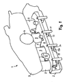
- suction device 1 for the supply of combustion air to the cylinders of an internal combustion engine comprises a mounting flange 2 made of plastic with a plurality of intake pipes 9, which is supplied via an upstream air distributor housing 3 with a central intake port 4 combustion air.
- a fuel distributor 5 is mounted with a high-pressure line, which is supplied via a feed nozzle 10 under high pressure fuel, which is distributed to the individual cylinders of the internal combustion engine.
- the supply nozzle 10 is located on a mounting plate 6, which is connected to the high pressure line of the fuel rail 5, in particular soldered, and on the top of the fuel rail extends.
- From the mounting plate 6 collar side mounting arms 7, which extend into the recesses between the adjacent intake pipes 9 of the mounting flange 2.
- holes 8 are introduced, can be inserted into the screws for connection to an underlying Zylinderkopfflansch and passed through the mounting flange 2.
- sockets 11 are connected to the mounting plate, which extend down toward the cylinder head and over which the mounting plate 6 are to be connected to the fuel rail 5 with the cylinder head.
- the number of bushes 11 corresponds to the number of intake pipes 9, which in turn corresponds to the number of cylinders of the internal combustion engine; if necessary, the number of sockets or the intake pipes can also differ from the number of cylinders.
- a pressure sensor 12 via which the fuel pressure in the high-pressure line 5 is to be measured, is arranged on the fuel distributor 5.
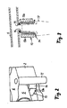
- Fig. 1 in conjunction with the cut-out magnification Fig. 2 and the sectional view to Fig. 3 can be seen on the mounting flange 2, the number of intake pipes 9 corresponding bracket pairs molded plastic 13, in which nozzle cups 14 are added, which are arranged on the underside of the fuel rail 5 and fixedly connected to it for example by means of soldering.
- the nozzle cups 14 have, inter alia, the function of holding elements, which are received positively in the pairs of clamps 13. Since the fuel distributor 5 rests with the mounting plate 6 on the mounting flange 2 of the suction device, thereby the mounting flange 2 is connected to the underlying cylinder head.
- each pair of brackets 13 comprises two cooperating bracket parts 13a and 13b, which define a receiving opening into which the nozzle cup 14 can be inserted and in which the nozzle cup is received positively.
- the nozzle cup 14 can be placed on a fuel nozzle 17, which is connected to the cylinder head and projects into a cylinder of the internal combustion engine.
- a flow opening 16 is introduced, which is aligned with a corresponding flow opening 15 in the wall of the fuel rail 5. The fuel flows via the flow-through openings 15 and 16 into the fuel nozzle 17 and is injected via this into the cylinder of the internal combustion engine.
- the nozzle cup 14 is appropriate as well as the fuel manifold made of metal and is suitably soldered to the fuel rail; but there are also other types of connections into consideration. It may also be expedient to provide a sealing ring on the fuel nozzle.
Landscapes
- Engineering & Computer Science (AREA)
- Chemical & Material Sciences (AREA)
- Combustion & Propulsion (AREA)
- Mechanical Engineering (AREA)
- General Engineering & Computer Science (AREA)
- Manufacturing & Machinery (AREA)
- Fuel-Injection Apparatus (AREA)
- Cylinder Crankcases Of Internal Combustion Engines (AREA)
Description
- Die Erfindung bezieht sich auf ein Ansaugeinrichtung für eine Brennkraftmaschine nach dem Oberbegriff des Anspruches 1.
- Eine derartige Ansaugeinrichtung wird beispielsweise in der Druckschrift
DE 199 44 855 A1 beschrieben. Die Ansaugeinrichtung umfasst ein aus Kunststoff bestehendes Gehäuse mit mehreren Ansaugrohren, die von einem gemeinsamen, als Sammelraum ausgebildeten Luftsammler abzweigen und über die Verbrennungsluft den Zylindern der Brennkraftmaschine zuzuführen ist. Das Kunststoffgehäuse der Ansaugeinrichtung wird über einen Befestigungsflansch am Zylinderkopf der Brennkraftmaschine angeschraubt. Die Verschraubung erfordert einen gewissen Montageaufwand. Außerdem muss darauf geachtet werden, dass im Bereich der Befestigungspunkte keine unzulässig hohen Kraftspitzen entstehen, die zu einer Materialzerstörung führen könnten. - Aus der
US 6 260 537 A ist eine Ansaugeinrichtung für eine Brennkraftmaschine bekannt mit einem integrierten Kraftstoffverteiler. Die Einspritzdüsen sind mittels Schnapphaken an der Ansaugeinrichtung gehalten. - Der Erfindung liegt das Problem zugrunde, mit einfachen Maßnahmen die Voraussetzungen für eine dauerhafte Verbindung zwischen dem Gehäuse einer Ansaugeinrichtung und dem Zylinderkopf zu schaffen. Die Verbindung soll eine leichte Montage- und Demontage der Ansaugeinrichtung ermöglichen.
- Dieses Problem wird erfindungsgemäß mit den Merkmalen des Anspruches 1 gelöst. Die Unteransprüche geben zweckmäßige Weiterbildungen an.
- Bei der erfindungsgemäßen Ansaugeinrichtung sind an dem Kunststoff-Befestigungsflansch bzw. Kunststoffgehäuse Klammerpaare angespritzt, in denen Halteelemente formschlüssig aufnehmbar sind, die in Montageposition am Zylinderkopf abgestützt sind. Die Halteelemente können in die Klammerpaare eingeschoben bzw. eingesteckt werden und werden von den beiden ein Paar bildenden Klammerteilen formschlüssig umgriffen. Auf diese Weise werden die Montage und auch die Demontage der Ansaugeinrichtung wesentlich vereinfacht, da der Befestigungsflansch lediglich auf den Zylinderkopf aufgesetzt bzw. gesteckt zu werden braucht und Verschraubungen grundsätzlich entfallen können oder zumindest die Anzahl der Verschraubungen reduziert werden kann.
- Für den Fall, dass zusätzliche Verschraubungen vorgesehen sind, bietet die Steckmöglichkeit des Befestigungsflansches den Vorteil einer zentrierten Ausrichtung der Schraubverbindungen zwischen dem Befestigungsflansch und dem Zylinderkopf. Montagekräfte können am Ort ihres Auftretens in den Zylinderkopf eingeleitet werden.
- Die Klammerpaare können im Spritzgussverfahren bei der Herstellung des Befestigungsflansches der Ansaugeinrichtung einteilig bzw. einstückig mit diesem hergestellt werden. Üblicherweise ist jedem Ansaugrohr ein Klammerpaar zugeordnet, wobei die Zahl der Ansaugrohre in der Regel der Zylinderanzahl der Brennkraftmaschine entspricht. Da eine Mehrzahl von Klammerpaaren vorgesehen ist, werden die Halte- und insbesondere die Montagekräfte zwischen dem Befestigungsflansch und dem Zylinderkopf über die Länge des Befestigungsflansches verteilt, wodurch die Gefahr einer Materialüberlastung reduziert ist. Die Krafteinleitung erfolgt im Bereich der Klammerpaare und der darin aufgenommene Halteelemente.
- Erfindungsgemäß sind die Halteelemente, welche in den Klammerpaaren aufgenommen und in Montageposition am Zylinderkopf gehalten sind, an einem Kraftstoffverteiler befestigt, der separat vom Befestigungsflansch ausgeführt ist. Über die Halteelemente wird eine zusätzliche Verbindung zwischen dem Kraftstoffverteiler und dem Befestigungsflansch geschaffen, so dass weitere Verbindungen zwischen diesen beiden Bauteilen entfallen können oder aber die Anzahl derartiger Verbindungen reduziert werden kann. Ein weiterer Vorteil ist darin zu sehen, dass der Befestigungsflansch in Montageposition zwischen dem Kraftstoffverteiler und dem Zylinderkopf eingeklemmt werden kann, was zur Folge hat, dass der auf dem Befestigungsflansch aufliegende Kraftstoffverteiler über seine gesamte Länge gleichmäßig einen Anpressdruck auf den Befestigungsflansch ausübt, wodurch jegliche Kraftspitzen vermieden werden. Der Kraftstoffverteiler besteht vorteilhaft aus Metall und ist daher in der Lage, problem- und gefahrlos höhere Kräfte aufzunehmen, die über die Halteelemente auf den Kraftstoffverteiler übertragen werden. Für den Fall, dass gemäß einer zweckmäßigen Ausführung die Halteelemente fest mit dem Kraftstoffverteiler verbunden sind, wird bei einem Einsetzen der Halteelemente in die hierfür vorgesehenen Klammerpaare zugleich eine formschlüssige Verbindung zwischen Befestigungsflansch und Kraftstoffverteiler geschaffen. Bei der Montage der gesamten Vorrichtung am Zylinderkopf müssen die Halteelemente lediglich zusätzlich in korrespondierende Gegenstücke am Zylinderkopf aufgesetzt bzw. mit diesem verbunden werden.
- Die Haltelemente können als so genannte Düsentassen ausgeführt sein, welche Tassenform aufweisen und deren Boden der Kraftstoffverteiler zugewandt ist, wobei im Boden eine Durchströmöffnung zur Strömungsverbindung mit dem Kraftstoffverteiler eingebracht ist. Die offene Seite der Düsentassen ist auf Kraftstoffdüsen am Zylinderkopf aufsetzbar, so dass der Kraftstoff aus der Hochdruckleitung des Kraftstoffverteilers über die Düsentassen den Kraftstoffdüsen zuführbar ist. Den Düsentassen kommt in dieser Ausführung die zusätzliche Funktion der Kraftstoffweiterleitung von der Hochdruckleitung in die Kraftstoffdüsen zu.
- Weitere Vorteile und zweckmäßige Ausführungen sind den weiteren Ansprüchen, der Figurenbeschreibung und den Zeichnungen zu entnehmen. Es zeigen:
- Fig. 1
- eine perspektivische Ansicht einer Ansaugeinrichtung für eine Brennkraftmaschine mit einem Befestigungsflansch und einem Luftverteilergehäuse und mit einer am Befestigungsflansch befestigten Kraftstoffverteiler,
- Fig. 2
- eine Ausschnittvergrößerung aus
Fig. 1 aus dem Bereich eines am Befestigungsflansch angespritzten Klammerpaares, in welchem eine mit der Kraftstoffverteiler verbundene Düsentasse aufgenommen ist, - Fig. 3
- einen Schnitt durch das Klammerpaar und die mit der Kraftstoffverteiler verbundene Düsentasse, die auf eine Kraftstoffdüse aufgesetzt ist.
- In den Figuren sind gleiche Bauteile mit gleichen Bezugszeichen versehen.
- Die in
Fig. 1 dargestellte Ansaugeinrichtung 1 für die Zufuhr von Verbrennungsluft zu den Zylindern einer Brennkraftmaschine umfasst einen Befestigungsflansch 2 aus Kunststoff mit einer Mehrzahl von Ansaugrohren 9, denen über ein vorgeschaltetes Luftverteilergehäuse 3 mit einer zentralen Ansaugöffnung 4 Verbrennungsluft zuzuführen ist. Auf den Befestigungsflansch 2 ist ein Kraftstoffverteiler 5 mit einer Hochdruckleitung aufgesetzt, der über einen Zuführstutzen 10 unter Hockdruck stehender Kraftstoff zuführbar ist, welcher auf die einzelnen Zylinder der Brennkraftmaschine verteilt wird. Der Zuführstutzen 10 befindet sich auf einer Befestigungsplatte 6, welche mit der Hochdruckleitung des Kraftstoffverteilers 5 verbunden ist, insbesondere angelötet ist, und sich über die Oberseite der Kraftstoffverteilers erstreckt. Von der Befestigungsplatte 6 kragen seitliche Befestigungsarme 7 aus, die sich in die Ausnehmungen zwischen den benachbarten Ansaugrohren 9 des Befestigungsflansches 2 erstrecken. In die Befestigungsarme 7 sind Bohrungen 8 eingebracht, in die Schrauben zur Verbindung mit einem darunter liegenden Zylinderkopfflansch eingesteckt und durch den Befestigungsflansch 2 hindurchgeführt werden können. - Auf der den Befestigungsarmen 7 gegenüberliegenden Seite der Befestigungsplatte 6 sind Buchsen 11 mit der Befestigungsplatte verbunden, welche sich nach unten in Richtung Zylinderkopf erstrecken und über die die Befestigungsplatte 6 mit dem Kraftstoffverteiler 5 mit dem Zylinderkopf zu verbinden sind. Die Anzahl der Buchsen 11 entspricht der Anzahl an Ansaugrohren 9, die wiederum der Zylinderanzahl der Brennkraftmaschine entspricht; gegebenenfalls kann die Anzahl der Buchsen bzw. der Ansaugrohre auch von der Zylinderanzahl abweichen.
- Des Weiteren ist auf dem Kraftstoffverteiler 5 ein Drucksensor 12 angeordnet, über den der Kraftstoffdruck in der Hochdruckleitung 5 zu messen ist.
- Wie
Fig. 1 in Verbindung mit der Ausschnittvergrößerung nachFig. 2 und der Schnittdarstellung nachFig. 3 zu entnehmen, sind am Befestigungsflansch 2 der Anzahl an Ansaugrohren 9 entsprechende Klammerpaare 13 aus Kunststoff angespritzt, in welchen Düsentassen 14 aufgenommen sind, die auf der Unterseite des Kraftstoffverteilers 5 angeordnet und beispielsweise mittels Löten fest mit diesem verbunden sind. Die Düsentassen 14 haben die unter anderem die Funktion von Halteelementen, welche in den Klammerpaaren 13 formschlüssig aufgenommen sind. Da der Kraftstoffverteiler 5 mit der Befestigungsplatte 6 auf dem Befestigungsflansch 2 der Ansaugeinrichtung aufliegt, wird hierdurch auch das Befestigungsflansch 2 mit dem darunter liegenden Zylinderkopf verbunden. - Der Schnittdarstellung nach
Fig. 3 ist zu entnehmen, dass jedes Klammerpaar 13 zwei zusammenwirkende Klammerteile 13a und 13b umfasst, die eine Aufnahmeöffnung begrenzen, in die die Düsentasse 14 einschiebbar ist und in der die Düsentasse formschlüssig aufgenommen ist. Die Düsentasse 14 ist auf eine Kraftstoffdüse 17 aufsetzbar, die mit dem Zylinderkopf verbunden ist und in einen Zylinder der Brennkraftmaschine einragt. In den dem Kraftstoffverteiler 5 zugewandten Boden der Düsentasse 14 ist eine Durchströmöffnung 16 eingebracht, die mit einer korrespondierenden Durchströmöffnung 15 in der Wandung des Kraftstoffverteilers 5 fluchtet. Der Kraftstoff strömt über die Durchströmöffnungen 15 und 16 in die Kraftstoffdüse 17 und wird über diese in den Zylinder der Brennkraftmaschine eingespritzt. - Die Düsentasse 14 besteht zweckmäßig ebenso wie die Kraftstoffverteiler aus Metall und ist zweckmäßig an den Kraftstoffverteiler angelötet; es kommen aber auch andere Verbindungsarten in Betracht. Es kann außerdem zweckmäßig sein, auf der Kraftstoffdüse einen Dichtring vorzusehen.
Claims (8)
- Ansaugeinrichtung für eine Brennkraftmaschine, bestehend aus einem Befestigungsflansch (2) mit mehreren Ansaugrohren (9) und einer Befestigungseinrichtung zur Befestigung des Befestigungsflansches (2) am Zylinderkopf der Brennkraftmaschine,wobei die Befestigungseinrichtung Klammerpaare (13) umfasst, in denen Halteelemente formschlüssig aufnehmbar sind, welche in der Abstützung zum Zylinderkopf liegen,
dadurch gekennzeichnet,
dass die Klammerpaare (13) am Befestigungsflansch (2) der Ansaugeinrichtung (1) angespritzt sind, wobei die Halteelemente an einem Kraftstoffverteiler (5) befestigt sind, der an dem Befestigungsflansch (2) abgestützt ist. - Ansaugeinrichtung nach Anspruch 1,
dadurch gekennzeichnet,
dass die Halteelemente Düsentassen (14) sind, welche in Montageposition auf Kraftstoffdüsen (17) aufgesetzt sind. - Ansaugeinrichtung nach Anspruch 2,
dadurch gekennzeichnet,
dass die Düsentassen (14) und der Kraftstoffverteiler (5) aus Metall gefertigt und die Düsentassen (14) an dem Kraftstoffverteiler (5) angelötet sind. - Ansaugeinrichtung nach Anspruch 3,
dadurch gekennzeichnet,
dass der Kraftstoffverteiler (5) an einer Befestigungsplatte (6) abgestützt ist, die mit dem Befestigungsflansch (2) verschraubt ist. - Ansaugeinrichtung nach Anspruch 4,
dadurch gekennzeichnet,
dass einteilig mit der Befestigungsplatte (6) ausgeführte Befestigungsarme (7) vorgesehen sind, über die die Befestigungsplatte (6) mit dem Befestigungsflansch (2) verschraubbar ist. - Ansaugeinrichtung nach einem der Ansprüche 1 bis 5,
dadurch gekennzeichnet,
dass an der Befestigungsplatte (6) Befestigungsbuchsen (11) zur Befestigung am Zylinderkopf vorgesehen sind. - Ansaugeinrichtung nach einem der Ansprüche 1 bis 6,
dadurch gekennzeichnet,
dass ein Luftverteilergehäuse (3) mit dem Befestigungsflansch (2) verbunden ist. - Ansaugeinrichtung nach einem der Ansprüche 1 bis 7,
dadurch gekennzeichnet,
dass die Anzahl der Klammerpaare (13) der Anzahl an Ansaugrohren (9) entspricht.
Applications Claiming Priority (2)
| Application Number | Priority Date | Filing Date | Title |
|---|---|---|---|
| DE2003154687 DE10354687A1 (de) | 2003-11-22 | 2003-11-22 | Ansaugeinrichtung für eine Brennkraftmaschine |
| DE10354687 | 2003-11-22 |
Publications (3)
| Publication Number | Publication Date |
|---|---|
| EP1533514A2 EP1533514A2 (de) | 2005-05-25 |
| EP1533514A3 EP1533514A3 (de) | 2010-09-22 |
| EP1533514B1 true EP1533514B1 (de) | 2012-08-01 |
Family
ID=34428862
Family Applications (1)
| Application Number | Title | Priority Date | Filing Date |
|---|---|---|---|
| EP20040104981 Expired - Lifetime EP1533514B1 (de) | 2003-11-22 | 2004-10-12 | Ansaugeinrichtung für eine Brennkraftmaschine |
Country Status (2)
| Country | Link |
|---|---|
| EP (1) | EP1533514B1 (de) |
| DE (1) | DE10354687A1 (de) |
Families Citing this family (4)
| Publication number | Priority date | Publication date | Assignee | Title |
|---|---|---|---|---|
| EP2148076A1 (de) * | 2008-07-24 | 2010-01-27 | Magneti Marelli Powertrain S.p.A. | Ansaugeinrichtung für eine Brennkraftmaschine |
| DE102009053986A1 (de) | 2009-11-23 | 2011-05-26 | Mahle International Gmbh | Flanschvorrichtung und Saugnalage |
| FR2965310B1 (fr) | 2010-09-27 | 2014-09-19 | Nature And People First | Procede et installation de production d'energie electrique d'appoint |
| FR2965308B1 (fr) | 2010-09-29 | 2015-03-06 | Mark Iv Systemes Moteurs Sa | Module fonctionnel d'alimentation en air integrant une rampe d'injection |
Family Cites Families (9)
| Publication number | Priority date | Publication date | Assignee | Title |
|---|---|---|---|---|
| JPS59200061A (ja) * | 1983-04-25 | 1984-11-13 | Honda Motor Co Ltd | 燃料噴射装置 |
| DE69200427T2 (de) * | 1991-04-04 | 1995-02-16 | Toyota Motor Co Ltd | Kraftstoffeinspritzvorrichtung einer Brennkraftmaschine. |
| US5394850A (en) * | 1993-11-19 | 1995-03-07 | Siemens Electric Limited | Top-feed fuel injector mounting in an integrated air-fuel system |
| DE19528047A1 (de) * | 1995-07-31 | 1997-02-06 | Bosch Gmbh Robert | Brennkraftmaschine mit einem daran befestigten Saugmodul bzw. Saugrohr und Verfahren zur Befestigung eines Saugmoduls bzw. Saugrohrs an einer Brennkraftmaschine |
| JP3620034B2 (ja) * | 1997-03-18 | 2005-02-16 | 株式会社デンソー | 内燃機関用吸気装置 |
| US6260537B1 (en) * | 1998-02-20 | 2001-07-17 | Delphi Technologies, Inc. | Side feed fuel injector and integrated fuel rail/intake manifold |
| DE19920195B4 (de) * | 1999-05-03 | 2007-12-06 | Audi Ag | Luftansaugsystem für eine mehrzylindrige Brennkraftmaschine |
| DE19960223A1 (de) * | 1999-07-15 | 2001-01-18 | Mann & Hummel Filter | Saugmodul für eine Brennkraftmaschine |
| DE19962987A1 (de) * | 1999-12-24 | 2001-07-05 | Mahle Filtersysteme Gmbh | Kolbenmotor |
-
2003
- 2003-11-22 DE DE2003154687 patent/DE10354687A1/de not_active Withdrawn
-
2004
- 2004-10-12 EP EP20040104981 patent/EP1533514B1/de not_active Expired - Lifetime
Also Published As
| Publication number | Publication date |
|---|---|
| DE10354687A1 (de) | 2005-06-16 |
| EP1533514A2 (de) | 2005-05-25 |
| EP1533514A3 (de) | 2010-09-22 |
Similar Documents
| Publication | Publication Date | Title |
|---|---|---|
| DE2908095C2 (de) | Kraftstoffeinspritzanlage für Brennkraftmaschinen | |
| DE8717886U1 (de) | Brennstoffeinspritzvorrichtung | |
| DE102009050337A1 (de) | Bauteileeinheit für ein Kraftstoffsystem einer Brennkraftmaschine sowie Brennkraftmaschine | |
| EP2504558B1 (de) | Flanschvorrichtung und sauganlage | |
| DE69712444T2 (de) | Brennstoffpumpenmodul für Brennstofftank eines Fahrzeugs | |
| DE102017209492A1 (de) | Halterung zur Befestigung eines Sensors, insbesondere Radarsensors, an einem Fahrzeug und ein System aus einer Halterung und dem Sensor | |
| EP1240423B1 (de) | Kolbenmotor | |
| EP2905461B1 (de) | Brennstoffeinspritzanlage mit einer Brennstoff führenden Komponente, einem Brennstoffeinspritzventil und einem Halter | |
| EP1722096B1 (de) | Kraftstoffinjektor mit einem Leckageanschluss | |
| EP1533514B1 (de) | Ansaugeinrichtung für eine Brennkraftmaschine | |
| DE102014207221A1 (de) | Kraftstofffördervorrichtung für einen Satteltank | |
| DE3415780A1 (de) | Kraftstoffeinspritzsystem | |
| EP2414646B1 (de) | Einspritzeinrichtung für harnstoffwasserlösung | |
| DE4228155C1 (de) | Vorrichtung zur Befestigung mindestens einer freiliegenden Leitung an einem Befestigungskörper, insbesondere Kraftstoffilter für eine Brennkraftmaschine | |
| DE102009014399B3 (de) | Kraftstoffverteiler mit Halterung | |
| DE102005033139A1 (de) | Niederhaltevorrichtung | |
| DE102012004595A1 (de) | Verteilermodul für in eine Auspuffleitung zu injizierendes Additiv | |
| EP0658456B1 (de) | Saugstrahlpumpeneinheit | |
| DE102012104480B3 (de) | Vorrichtung zur Befestigung eines Kraftstoffverteilers | |
| WO1997030282A1 (de) | Ansaugsystem | |
| DE19941770A1 (de) | Rücklaufeinrichtung | |
| DE10041484A1 (de) | Brennkraftmaschine, insbesondere für Motorräder | |
| EP1715168B1 (de) | Integriertes Einspritzsystem | |
| DE102006026656A1 (de) | Haltebauteil für eine Brennkraftmaschine, die mit einem Filter für Betriebsstoffe ausgestattet ist | |
| DE102014204270B4 (de) | Anordnung aus schlauchartiger Kraftstoffleitung und elektrisch leitfähigem Kontaktelement |
Legal Events
| Date | Code | Title | Description |
|---|---|---|---|
| PUAI | Public reference made under article 153(3) epc to a published international application that has entered the european phase |
Free format text: ORIGINAL CODE: 0009012 |
|
| AK | Designated contracting states |
Kind code of ref document: A2 Designated state(s): AT BE BG CH CY CZ DE DK EE ES FI FR GB GR HU IE IT LI LU MC NL PL PT RO SE SI SK TR |
|
| AX | Request for extension of the european patent |
Extension state: AL HR LT LV MK |
|
| PUAL | Search report despatched |
Free format text: ORIGINAL CODE: 0009013 |
|
| AK | Designated contracting states |
Kind code of ref document: A3 Designated state(s): AT BE BG CH CY CZ DE DK EE ES FI FR GB GR HU IE IT LI LU MC NL PL PT RO SE SI SK TR |
|
| AX | Request for extension of the european patent |
Extension state: AL HR LT LV MK |
|
| 17P | Request for examination filed |
Effective date: 20101027 |
|
| 17Q | First examination report despatched |
Effective date: 20110414 |
|
| AKX | Designation fees paid |
Designated state(s): AT BE BG CH CY CZ DE DK EE ES FI FR GB GR HU IE IT LI LU MC NL PL PT RO SE SI SK TR |
|
| GRAP | Despatch of communication of intention to grant a patent |
Free format text: ORIGINAL CODE: EPIDOSNIGR1 |
|
| GRAS | Grant fee paid |
Free format text: ORIGINAL CODE: EPIDOSNIGR3 |
|
| GRAA | (expected) grant |
Free format text: ORIGINAL CODE: 0009210 |
|
| AK | Designated contracting states |
Kind code of ref document: B1 Designated state(s): AT BE BG CH CY CZ DE DK EE ES FI FR GB GR HU IE IT LI LU MC NL PL PT RO SE SI SK TR |
|
| REG | Reference to a national code |
Ref country code: GB Ref legal event code: FG4D Free format text: NOT ENGLISH |
|
| RIN1 | Information on inventor provided before grant (corrected) |
Inventor name: DOBUSCH, HEINZ Inventor name: ZBIRAL, ROBERT |
|
| REG | Reference to a national code |
Ref country code: CH Ref legal event code: EP Ref country code: AT Ref legal event code: REF Ref document number: 568838 Country of ref document: AT Kind code of ref document: T Effective date: 20120815 |
|
| REG | Reference to a national code |
Ref country code: IE Ref legal event code: FG4D Free format text: LANGUAGE OF EP DOCUMENT: GERMAN |
|
| REG | Reference to a national code |
Ref country code: NL Ref legal event code: VDEP Effective date: 20120801 |
|
| REG | Reference to a national code |
Ref country code: DE Ref legal event code: R096 Ref document number: 502004013657 Country of ref document: DE Effective date: 20130117 |
|
| PG25 | Lapsed in a contracting state [announced via postgrant information from national office to epo] |
Ref country code: FI Free format text: LAPSE BECAUSE OF FAILURE TO SUBMIT A TRANSLATION OF THE DESCRIPTION OR TO PAY THE FEE WITHIN THE PRESCRIBED TIME-LIMIT Effective date: 20120801 Ref country code: CY Free format text: LAPSE BECAUSE OF FAILURE TO SUBMIT A TRANSLATION OF THE DESCRIPTION OR TO PAY THE FEE WITHIN THE PRESCRIBED TIME-LIMIT Effective date: 20120801 |
|
| PG25 | Lapsed in a contracting state [announced via postgrant information from national office to epo] |
Ref country code: GR Free format text: LAPSE BECAUSE OF FAILURE TO SUBMIT A TRANSLATION OF THE DESCRIPTION OR TO PAY THE FEE WITHIN THE PRESCRIBED TIME-LIMIT Effective date: 20121102 Ref country code: SI Free format text: LAPSE BECAUSE OF FAILURE TO SUBMIT A TRANSLATION OF THE DESCRIPTION OR TO PAY THE FEE WITHIN THE PRESCRIBED TIME-LIMIT Effective date: 20120801 Ref country code: PL Free format text: LAPSE BECAUSE OF FAILURE TO SUBMIT A TRANSLATION OF THE DESCRIPTION OR TO PAY THE FEE WITHIN THE PRESCRIBED TIME-LIMIT Effective date: 20120801 Ref country code: SE Free format text: LAPSE BECAUSE OF FAILURE TO SUBMIT A TRANSLATION OF THE DESCRIPTION OR TO PAY THE FEE WITHIN THE PRESCRIBED TIME-LIMIT Effective date: 20120801 Ref country code: PT Free format text: LAPSE BECAUSE OF FAILURE TO SUBMIT A TRANSLATION OF THE DESCRIPTION OR TO PAY THE FEE WITHIN THE PRESCRIBED TIME-LIMIT Effective date: 20121203 |
|
| PG25 | Lapsed in a contracting state [announced via postgrant information from national office to epo] |
Ref country code: NL Free format text: LAPSE BECAUSE OF FAILURE TO SUBMIT A TRANSLATION OF THE DESCRIPTION OR TO PAY THE FEE WITHIN THE PRESCRIBED TIME-LIMIT Effective date: 20120801 |
|
| BERE | Be: lapsed |
Owner name: MANN+HUMMEL G.M.B.H. Effective date: 20121031 |
|
| PG25 | Lapsed in a contracting state [announced via postgrant information from national office to epo] |
Ref country code: RO Free format text: LAPSE BECAUSE OF FAILURE TO SUBMIT A TRANSLATION OF THE DESCRIPTION OR TO PAY THE FEE WITHIN THE PRESCRIBED TIME-LIMIT Effective date: 20120801 Ref country code: EE Free format text: LAPSE BECAUSE OF FAILURE TO SUBMIT A TRANSLATION OF THE DESCRIPTION OR TO PAY THE FEE WITHIN THE PRESCRIBED TIME-LIMIT Effective date: 20120801 Ref country code: ES Free format text: LAPSE BECAUSE OF FAILURE TO SUBMIT A TRANSLATION OF THE DESCRIPTION OR TO PAY THE FEE WITHIN THE PRESCRIBED TIME-LIMIT Effective date: 20121112 Ref country code: CZ Free format text: LAPSE BECAUSE OF FAILURE TO SUBMIT A TRANSLATION OF THE DESCRIPTION OR TO PAY THE FEE WITHIN THE PRESCRIBED TIME-LIMIT Effective date: 20120801 Ref country code: DK Free format text: LAPSE BECAUSE OF FAILURE TO SUBMIT A TRANSLATION OF THE DESCRIPTION OR TO PAY THE FEE WITHIN THE PRESCRIBED TIME-LIMIT Effective date: 20120801 |
|
| PG25 | Lapsed in a contracting state [announced via postgrant information from national office to epo] |
Ref country code: SK Free format text: LAPSE BECAUSE OF FAILURE TO SUBMIT A TRANSLATION OF THE DESCRIPTION OR TO PAY THE FEE WITHIN THE PRESCRIBED TIME-LIMIT Effective date: 20120801 Ref country code: IT Free format text: LAPSE BECAUSE OF FAILURE TO SUBMIT A TRANSLATION OF THE DESCRIPTION OR TO PAY THE FEE WITHIN THE PRESCRIBED TIME-LIMIT Effective date: 20120801 Ref country code: MC Free format text: LAPSE BECAUSE OF NON-PAYMENT OF DUE FEES Effective date: 20121031 |
|
| REG | Reference to a national code |
Ref country code: CH Ref legal event code: PL |
|
| PLBE | No opposition filed within time limit |
Free format text: ORIGINAL CODE: 0009261 |
|
| STAA | Information on the status of an ep patent application or granted ep patent |
Free format text: STATUS: NO OPPOSITION FILED WITHIN TIME LIMIT |
|
| 26N | No opposition filed |
Effective date: 20130503 |
|
| REG | Reference to a national code |
Ref country code: IE Ref legal event code: MM4A |
|
| GBPC | Gb: european patent ceased through non-payment of renewal fee |
Effective date: 20121101 |
|
| REG | Reference to a national code |
Ref country code: FR Ref legal event code: ST Effective date: 20130628 |
|
| PG25 | Lapsed in a contracting state [announced via postgrant information from national office to epo] |
Ref country code: BE Free format text: LAPSE BECAUSE OF NON-PAYMENT OF DUE FEES Effective date: 20121031 Ref country code: BG Free format text: LAPSE BECAUSE OF FAILURE TO SUBMIT A TRANSLATION OF THE DESCRIPTION OR TO PAY THE FEE WITHIN THE PRESCRIBED TIME-LIMIT Effective date: 20121101 Ref country code: LI Free format text: LAPSE BECAUSE OF NON-PAYMENT OF DUE FEES Effective date: 20121031 Ref country code: CH Free format text: LAPSE BECAUSE OF NON-PAYMENT OF DUE FEES Effective date: 20121031 Ref country code: IE Free format text: LAPSE BECAUSE OF NON-PAYMENT OF DUE FEES Effective date: 20121012 |
|
| REG | Reference to a national code |
Ref country code: DE Ref legal event code: R097 Ref document number: 502004013657 Country of ref document: DE Effective date: 20130503 |
|
| PG25 | Lapsed in a contracting state [announced via postgrant information from national office to epo] |
Ref country code: FR Free format text: LAPSE BECAUSE OF NON-PAYMENT OF DUE FEES Effective date: 20121031 |
|
| PG25 | Lapsed in a contracting state [announced via postgrant information from national office to epo] |
Ref country code: GB Free format text: LAPSE BECAUSE OF NON-PAYMENT OF DUE FEES Effective date: 20121101 |
|
| REG | Reference to a national code |
Ref country code: AT Ref legal event code: MM01 Ref document number: 568838 Country of ref document: AT Kind code of ref document: T Effective date: 20121031 |
|
| PG25 | Lapsed in a contracting state [announced via postgrant information from national office to epo] |
Ref country code: AT Free format text: LAPSE BECAUSE OF NON-PAYMENT OF DUE FEES Effective date: 20121031 |
|
| PG25 | Lapsed in a contracting state [announced via postgrant information from national office to epo] |
Ref country code: TR Free format text: LAPSE BECAUSE OF FAILURE TO SUBMIT A TRANSLATION OF THE DESCRIPTION OR TO PAY THE FEE WITHIN THE PRESCRIBED TIME-LIMIT Effective date: 20120801 |
|
| PG25 | Lapsed in a contracting state [announced via postgrant information from national office to epo] |
Ref country code: LU Free format text: LAPSE BECAUSE OF NON-PAYMENT OF DUE FEES Effective date: 20121012 |
|
| PG25 | Lapsed in a contracting state [announced via postgrant information from national office to epo] |
Ref country code: HU Free format text: LAPSE BECAUSE OF FAILURE TO SUBMIT A TRANSLATION OF THE DESCRIPTION OR TO PAY THE FEE WITHIN THE PRESCRIBED TIME-LIMIT Effective date: 20041012 |
|
| PGFP | Annual fee paid to national office [announced via postgrant information from national office to epo] |
Ref country code: DE Payment date: 20171019 Year of fee payment: 14 |
|
| REG | Reference to a national code |
Ref country code: DE Ref legal event code: R119 Ref document number: 502004013657 Country of ref document: DE |
|
| PG25 | Lapsed in a contracting state [announced via postgrant information from national office to epo] |
Ref country code: DE Free format text: LAPSE BECAUSE OF NON-PAYMENT OF DUE FEES Effective date: 20190501 |