EP1533412A2 - Trommelwaschmaschine - Google Patents
Trommelwaschmaschine Download PDFInfo
- Publication number
- EP1533412A2 EP1533412A2 EP04254799A EP04254799A EP1533412A2 EP 1533412 A2 EP1533412 A2 EP 1533412A2 EP 04254799 A EP04254799 A EP 04254799A EP 04254799 A EP04254799 A EP 04254799A EP 1533412 A2 EP1533412 A2 EP 1533412A2
- Authority
- EP
- European Patent Office
- Prior art keywords
- tub
- drum
- water supply
- wash water
- washing machine
- Prior art date
- Legal status (The legal status is an assumption and is not a legal conclusion. Google has not performed a legal analysis and makes no representation as to the accuracy of the status listed.)
- Withdrawn
Links
Images


Classifications
-
- D—TEXTILES; PAPER
- D06—TREATMENT OF TEXTILES OR THE LIKE; LAUNDERING; FLEXIBLE MATERIALS NOT OTHERWISE PROVIDED FOR
- D06F—LAUNDERING, DRYING, IRONING, PRESSING OR FOLDING TEXTILE ARTICLES
- D06F39/00—Details of washing machines not specific to a single type of machines covered by groups D06F9/00 - D06F27/00
- D06F39/08—Liquid supply or discharge arrangements
- D06F39/088—Liquid supply arrangements
-
- D—TEXTILES; PAPER
- D06—TREATMENT OF TEXTILES OR THE LIKE; LAUNDERING; FLEXIBLE MATERIALS NOT OTHERWISE PROVIDED FOR
- D06F—LAUNDERING, DRYING, IRONING, PRESSING OR FOLDING TEXTILE ARTICLES
- D06F37/00—Details specific to washing machines covered by groups D06F21/00 - D06F25/00
- D06F37/26—Casings; Tubs
- D06F37/267—Tubs specially adapted for mounting thereto components or devices not provided for in preceding subgroups
-
- D—TEXTILES; PAPER
- D06—TREATMENT OF TEXTILES OR THE LIKE; LAUNDERING; FLEXIBLE MATERIALS NOT OTHERWISE PROVIDED FOR
- D06F—LAUNDERING, DRYING, IRONING, PRESSING OR FOLDING TEXTILE ARTICLES
- D06F39/00—Details of washing machines not specific to a single type of machines covered by groups D06F9/00 - D06F27/00
- D06F39/02—Devices for adding soap or other washing agents
- D06F39/024—Devices for adding soap or other washing agents mounted on the agitator or the rotating drum; Free body dispensers
-
- D—TEXTILES; PAPER
- D06—TREATMENT OF TEXTILES OR THE LIKE; LAUNDERING; FLEXIBLE MATERIALS NOT OTHERWISE PROVIDED FOR
- D06F—LAUNDERING, DRYING, IRONING, PRESSING OR FOLDING TEXTILE ARTICLES
- D06F39/00—Details of washing machines not specific to a single type of machines covered by groups D06F9/00 - D06F27/00
- D06F39/06—Arrangements for preventing or destroying scum
Definitions
- the present invention relates to a drum type washing machine, and more particularly, but not exclusively, to a drum type washing machine in which wash water fed to a tub via a water supply pipe is directly supplied into a drum, so that laundry contained in the drum is wetted by the wash water more rapidly.
- a drum type washing machine is an appliance for washing laundry contained in a drum by utilizing wash water generated during a rotation of the drum.
- a drum type washing machine includes a housing defining the appearance of the washing machine, a tub fixedly mounted in the housing, and adapted to contain wash water therein, and a drum rotatably mounted in the tub.
- a drive motor is installed at a side portion of the housing to rotate the drum.
- a plurality of through holes are perforated through the drum to allow the wash water in the tub to flow into the drum.
- a water supply valve to supply wash water into the tub
- a detergent box connected to the water supply valve via a connecting hose
- a water supply pipe for connecting the tub and detergent box.
- wash water is fed to the detergent box via the connecting hose, and is then supplied into the tub via the water supply pipe, along with the detergent contained in the detergent box.
- An access opening is formed at a front wall of the housing to allow laundry to be put into and taken out of the drum.
- a door is also mounted to the front wall of the housing around the access opening such that it is horizontally hingable to open and close the access opening.
- the water supply pipe which connects the detergent box and tub, is typically connected to the top of the tub. Due to such a water supply arrangement, the wash water supplied into the tub typically flows downwardly along an outer surface of the drum to gradually fill the interior of the tub from the bottom of the tub.
- wash water can flow into the drum through the through holes formed at the drum after passing through the connecting hose, detergent box, and water pipe in a sequential manner, in the opened state of the water valve, entering the tub to gradually fill the tub from the bottom of the tub, and then reaching a certain level in the water tub.
- the wash water introduced in the drum permeates the laundry contained in the drum.
- drum type washing machine comprising an improved water supply arrangement and capable of wetting laundry with wash water more rapidly.
- the present invention provides a drum type washing machine comprising a housing, a tub arranged in the housing to contain wash water therein, a drum rotatably mounted in the tub, a water supply pipe to supply wash water into the tub, and a water supply guide unit provided at the tub, to guide the wash water from the water supply pipe to be directly supplied into the drum.
- the present invention provides a drum type washing machine comprising a housing, a tub arranged in the housing to contain wash water therein, a drum rotatably mounted in the tub, a drum access opening provided at a front wall of the drum, a water supply pipe to supply wash water into the tub, and a water supply guide unit provided at the tub, to guide the wash water from the water supply pipe into the drum through the drum access opening.
- the tub preferably comprises a front wall having a tub access opening.
- the water supply guide unit is arranged at the front wall of the tub.
- the water supply guide unit preferably comprises a water supply hole formed at the front wall of the tub, and connected with an outlet of the water supply pipe, and a water supply guide member to guide the wash water introduced into the tub through the water supply hole to flow into the drum.
- the water supply hole and the water supply guide member are preferably arranged above the tub access opening to allow the wash water to fall due to the force of gravity.
- the water supply guide member preferably comprises an inner trough member arranged at an inner surface of the front wall of the tub to guide the wash water discharged from the water supply hole to flow toward the outside of the tub, and an outer trough member arranged at an outer surface of the front wall of the tub to guide the wash water flowing toward the outside of the tub in accordance with an operation of the inner trough member to flow toward the inside of the drum.
- the inner trough member is preferably arranged to cover the water supply hole and comprises a first inclined extension extending downwardly in a state of being inclined toward the outside of the tub.
- the outer trough member may be provided with a second inclined extension extending downwardly in a state of being inclined toward the inside of the tub.
- the first inclined extension is arranged over the second inclined extension.
- the housing preferably comprises a housing access opening at a front wall thereof facing the tub access opening, and a door to open and close the housing access opening.
- the door comprises a door frame to be supported by a portion of the front wall of the housing around the housing access opening in a closed state of the door, and a door glass extending inwardly from the door frame into the tub through the tub access opening by a predetermined length, to allow a user to view the interior of the tub from the outside.
- the second inclined extension feeds a portion of the wash water to the door glass.
- the second inclined extension preferably comprises at least one first guide portion extending into the tub by a predetermined extension length such that the wash water flowing along the second inclined extension falls onto the door glass, and at least one second guide portion extending into the tub by an extension length larger than that of the first guide portion such that the wash water flowing along the second inclined extension falls into the drum beyond the door glass.
- the at least one first guide portion preferably comprises a plurality of first guide portions, and the at least one second guide portion comprises a plurality of second guide portions.
- the first and second guide portions may be alternately arranged.
- the second inclined extension preferably comprises a trough at each of the first and second guide portions, and a crest between adjacent ones of the first and second guide portions, the wash water guided by the second inclined extension comprises constant flow directions respectively corresponding to the first and second guide portions.
- the drum type washing machine may further preferably comprise a bellows tube connected between the housing access opening and the tub access opening, to prevent leakage of wash water.
- the water supply hole may be arranged outside the bellows tube.
- the outer trough member may be arranged inside the bellows tube.
- FIGS. 1 and 2 a drum type washing machine according to an embodiment of the present invention is illustrated.
- the drum type washing machine comprises a housing 10 defining the appearance of the washing machine, and a tub 20 mounted in the housing 10, to contain wash water therein.
- the tub 20 is firmly supported by the housing 10 at upper and lower portions thereof via respective suspensions (not shown) and respective dampers 24 and comprises a drum 30 rotatably mounted therein.
- a drive motor 31 is installed at a side portion of the housing 10 to rotate the drum 30.
- a plurality of through holes 32 are perforated through the drum 30, to allow the wash water in the tub 20 to flow into the drum 30.
- a water supply valve 41 to supply wash water into the tub 20, a detergent box 42 to contain detergent therein, and a water supply pipe 43 to connect the tub 20 with the detergent box 42 are arranged at an upper portion of the housing 10.
- the water supply valve 41 and detergent box 42 are connected with each other by a connecting hose 44.
- wash water is fed to the detergent box 42 via the connecting hose 44, and is then supplied into the tub 20 via the water supply pipe 43, along with the detergent contained in the detergent box 42.
- a drainage pipe 45 and a drainage motor 46 are installed at a lower portion of the housing 10.
- a tub access opening 22 is formed at a front wall 21 of the tub 20 to allow laundry to be put into and taken out of the drum 30.
- a housing access opening 11 is also formed at a front wall of the housing 10 such that it is aligned with the tub access opening 22.
- a drum access opening 33 is formed at a front wall of the drum 30 such that it is aligned with the housing and tub access openings 11 and 22.
- a door 50 is hingably mounted to the front wall of the housing 10.
- the door 50 comprises a door frame 51 to be supported by a portion of the front wall of the housing 10 around the housing access opening 11 in a closed state of the door 50, and a door glass 52 provided at a central portion of the door frame 51 while extending inwardly into the interior of the tub 20 through the tub access opening 22 by a desired length to allow the user to view the interior of the tub 20 from the outside.
- a bellows tube 53 is connected between the housing access opening 11 and the tub access opening 22, to prevent the wash water in the tub 20 from leaking to the outside during operation of the washing machine.
- the interior of the tub 20 is maintained in a sealed state by the bellows tube 53.
- a water supply guide unit 60 is provided at the tub 20 to guide the wash water fed to the tub 20 via the water supply pipe 43 to be directly supplied into the drum 30. That is, the water supply guide unit 60 allows wash water to be supplied into the drum 30 through the drum access opening 33 immediately after supply of the wash water to the tub 20 is initiated, thereby allowing laundry contained in the drum 30 to be wetted by the wash water more rapidly, and thus, reducing the wash time of the laundry.
- the configuration of the water supply guide unit 60 will now be described in detail.
- the water supply guide unit 60 comprises a water supply hole 61 provide at the front wall 21 of the tub 20, and connected to an outlet of the water supply pipe 43, and a water supply guide member 70 provided at the front wall 21 of the tub 20, to guide wash water fed to the tub 20 through the water supply hole 61 to be immediately supplied into the drum 30.
- the water supply hole 61 and water supply guide member 70 are arranged above the tub access opening 22 so that wash water is supplied into the drum 30 due to the force of gravity without use of a pump or the like.
- the water supply guide member 70 comprises an inner trough member 80 arranged at an inner surface of the front wall 21 to guide wash water introduced into the tub 20 toward the outside of the tub 20, and an outer trough member 90 arranged at an outer surface of the front wall 21 to guide the wash water flowing toward the outside of the tub 20 in accordance with the guide of the inner trough member 80 to again flow toward the inside of the drum 30.
- the inner trough member 80 has an upper portion mounted to the inner surface of the front wall 21 while covering the water supply hole 61.
- the inner trough member 80 is also provided, at a lower end thereof, with a first inclined extension 81 extending downwardly from the lower end while being inclined toward the outside of the tub 20.
- an extension 23 extends from the front wall 21 around the tub access opening 22 toward the front wall of the housing 10.
- the outer trough member 90 is mounted, at an upper end thereof, to a free end of the extension 23 such that it is integral with the extension 23.
- the outer trough member 90 is provided, at a lower end thereof, with a second inclined extension 91 extending downwardly from the lower end while being inclined toward the inside of the tub 20.
- wash water fed to the water supply guide member 70 via the water supply pipe 43 is first introduced into the inner trough member 80.
- the wash water is then introduced into the outer trough member 90 as it is guided by the first inclined extension 81 of the inner trough member 80.
- the wash water is supplied into the drum 30 through the drum access opening 33 as it is guided by the second inclined extension 91.
- the first inclined extension 81 is arranged over the second inclined extension 91.
- the inner and outer trough members 80 and 90 forming the water supply guide member 70 are separately configured in such a manner that the inner trough member 80 is mounted to the inner surface of the front wall 21, whereas the outer trough member 90 is formed integrally with the front wall 21.
- the inner and outer trough members 80 and 90 may have an integral structure mounted to the front wall 21.
- the inner and outer trough members 80 and 90 have separate structures formed integrally with the front wall 21, respectively.
- the inner and outer trough members 80 and 90 have separate structures mounted to the inner and outer surfaces of the front wall 21, respectively.
- the impact point of the wash water falling into the drum 30 after being fed to the drum 30 via the water supply guide member 70 may vary, depending on the inclinations of the first and second inclined extensions 81 and 91. Accordingly, the inclinations of the first and second inclined extensions 81 and 91 are designed, taking into consideration the impact point of the wash water falling into the drum 30.
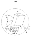
- the second inclined extension 91 supplies a portion of the wash water, fed into the drum 30, toward the door glass 52 of the door 50. That is, as shown in FIG. 5, the second inclined extension 91 comprises at least one first guide portion 92 extending into the tub 20 by a small extension length such that the wash water flowing along the second inclined extension 91 falls onto the door glass 52, and at least one second guide portion 93 extending into the tub 20 by an extension length larger than that of the first guide portion 92 such that the wash water flowing along the second inclined extension 91 falls into the drum 30 beyond the door glass 52.
- the second inclined extension 91 comprising the first and second guide portions 92 and 93
- a portion of the wash water guided to the drum via the water supply guide member 70 is directly supplied into the drum 30, to allow laundry contained in the drum 30 to be wetted more rapidly by the supplied wash water, whereas the remaining portion of the wash water is supplied into the drum 30 after falling onto the door glass 52, to remove foreign matter such as bubbles attached to the door glass 52. Accordingly, the user can easily visually identify the washed state of the laundry in the drum 30 through the door glass 52 from the outside.
- the second inclined extension 91 comprises a plurality of first guide portions 92 and a plurality of second guide portions 93 provided such that they are alternately arranged. That is, each first guide portion 92 is arranged between adjacent ones of the second guide portions 93, and each second guide portion 93 is arranged between adjacent ones of the first guide portions 92.
- the flow width of the wash water falling into the drum 30 and the flow width of the wash water falling onto the door glass 52 can be enlarged.
- Each of the first and second guide portions 92 and 93 comprises a trough 94. Also, a crest 95 is formed between adjacent ones of the first and second guide portions 92 and 93. By using the troughs 94 and crests 95, the wash water guided by the second inclined extension 91 flows constantly, respectively directed to the interior of the drum 30 and the door glass 52.
- the bellows tube 53 which is connected between the housing access opening 11 and the tub access opening 22 to seal the interior of the tub 20 in the closed state of the door 50, closes the water supply hole 61, or the outer trough member 90 of the water supply guide member 70, is exposed to the outside of the bellows tube 53, there is a difficulty in achieving the connection of the water supply pipe 43 or the supply of wash water into the drum 30. For this reason, it is preferred that the water supply hole 61 is arranged outside the bellows tube 53, and the outer trough member 90 is arranged inside the bellows tube 53.
- wash water fed to the tub 20 via the water supply pipe 43 is directly supplied into the drum 30 by the water supply guide unit 60 comprising the water supply hole 61 and water supply guide member 70, so that the laundry contained in the drum 30 can be wetted by the wash water more rapidly. Accordingly, it is possible to reduce the wash time for the laundry.
- a portion of the wash water, to be supplied into the drum 30, is fed to the door glass 52 of the door 50 by the first guide portions 92 provided at the second inclined extension 91 of the outer trough member 90 included in the water supply guide member 70. Accordingly, it is possible to effectively remove foreign matter such as bubbles attached to the door glass 52.
- wash water is fed to the detergent box 42 via the connecting hose 44, and is then introduced into the water supply pipe 43, along with detergent contained in the detergent box 42.
- the wash water is then fed to the tub 20 through the water supply hole 61 formed at the front wall 21 of the tub 20.
- the wash water fed to the tub 20 is guided by the first inclined extension 81 provided at the inner trough member 80 of the water supply guide member 70 to flow toward the outside of the tub 20 and then to reach the outer trough member 90 of the water supply guide member 70.
- the wash water reaching the outer trough member 90 is then guided by the second inclined extension 91 of the outer trough member 90 to flow toward the inside of the tub 20.
- the wash water guided by the first guide portions 92 of the second inclined extension 91 each having a small extension length falls onto the door glass 52, so that it removes foreign matter such as bubbles attached to the door glass 52 during a washing operation.
- the wash water guided by the second guide portions 93 each having an extension length larger than that of the first guide portions 92 falls into the drum 30 beyond the door glass 52, so that it immediately permeates the laundry contained in the drum 30.
- the laundry When the drum 30 rotates under this condition, the laundry is raised to the top of the drum 30 and dropped to the bottom of the drum 30, along with the wash water, in a sequential and repeated manner.
- the laundry is washed by the wash water generated in accordance with the above mentioned action of the laundry and wash water.
- the laundry can be completely washed within a reduced time because it has been wetted by the wash water immediately after the wash water has been supplied by the water supply guide unit 60.
- wash water fed to the tub via the water supply pipe is directly supplied into the drum by the water supply guide unit arranged at the front wall of the tub. Accordingly, laundry contained in the drum can be wetted by the wash water, immediately after the supply of the wash water. Thus, it is possible to reduce the wash time for the laundry.
- the water supply guide unit of the drum type washing machine guides a portion of the wash water, to be supplied into the drum, toward the door glass, to remove foreign matter such as bubbles attached to the door glass.
Landscapes
- Engineering & Computer Science (AREA)
- Textile Engineering (AREA)
- Main Body Construction Of Washing Machines And Laundry Dryers (AREA)
- Detail Structures Of Washing Machines And Dryers (AREA)
Applications Claiming Priority (2)
| Application Number | Priority Date | Filing Date | Title |
|---|---|---|---|
| KR1020030081561A KR101022225B1 (ko) | 2003-11-18 | 2003-11-18 | 드럼세탁기 |
| KR2003081561 | 2003-11-18 |
Publications (2)
| Publication Number | Publication Date |
|---|---|
| EP1533412A2 true EP1533412A2 (de) | 2005-05-25 |
| EP1533412A3 EP1533412A3 (de) | 2006-10-04 |
Family
ID=34431789
Family Applications (1)
| Application Number | Title | Priority Date | Filing Date |
|---|---|---|---|
| EP04254799A Withdrawn EP1533412A3 (de) | 2003-11-18 | 2004-08-10 | Trommelwaschmaschine |
Country Status (5)
| Country | Link |
|---|---|
| US (1) | US7322217B2 (de) |
| EP (1) | EP1533412A3 (de) |
| JP (1) | JP4105137B2 (de) |
| KR (1) | KR101022225B1 (de) |
| CN (1) | CN100519901C (de) |
Families Citing this family (13)
| Publication number | Priority date | Publication date | Assignee | Title |
|---|---|---|---|---|
| KR100751766B1 (ko) * | 2005-07-01 | 2007-08-24 | 주식회사 대우일렉트로닉스 | 드럼세탁기 |
| KR101253566B1 (ko) * | 2005-07-07 | 2013-04-11 | 삼성전자주식회사 | 드럼세탁기 |
| EP2063014B1 (de) * | 2007-11-21 | 2013-09-18 | LG Electronics Inc. | Waschmaschine |
| KR101435811B1 (ko) * | 2007-11-21 | 2014-08-29 | 엘지전자 주식회사 | 의류처리장치 |
| KR101521175B1 (ko) * | 2008-04-22 | 2015-05-20 | 삼성전자 주식회사 | 세탁기 및 그 제어방법 |
| EP2317001B1 (de) * | 2009-10-29 | 2016-05-25 | Electrolux Home Products Corporation N.V. | Haushaltsgerät mit wandbefestigung |
| KR101373617B1 (ko) | 2012-08-06 | 2014-03-12 | 동부대우전자 주식회사 | 벽걸이형 드럼세탁기 |
| AU2014404792B2 (en) * | 2014-08-28 | 2018-11-01 | Wuxi Little Swan Electric Co., Ltd. | Washing machine sprayer apparatus and drum washing machine having same |
| KR102402082B1 (ko) | 2015-06-30 | 2022-05-26 | 엘지전자 주식회사 | 의류처리장치 |
| CN208250683U (zh) * | 2018-02-14 | 2018-12-18 | 无锡小天鹅股份有限公司 | 滚筒洗衣机及其门封 |
| CN110158287B (zh) * | 2018-02-14 | 2024-03-05 | 无锡小天鹅电器有限公司 | 滚筒洗衣机及其门体和门玻璃 |
| CN110144695B (zh) * | 2018-02-14 | 2024-03-08 | 无锡小天鹅电器有限公司 | 滚筒洗衣机 |
| CN110396803B (zh) * | 2018-04-24 | 2022-04-05 | 青岛海尔洗涤电器有限公司 | 一种进水水流控制装置及洗衣机 |
Family Cites Families (15)
| Publication number | Priority date | Publication date | Assignee | Title |
|---|---|---|---|---|
| JPH0741115B2 (ja) | 1986-08-22 | 1995-05-10 | 株式会社日立製作所 | 洗濯機 |
| ES2007913A6 (es) | 1988-06-09 | 1989-07-01 | Balay Sa | Sistema de aclarado para lavadoras automaticas. |
| DE4210782A1 (de) | 1992-04-01 | 1993-10-07 | Licentia Gmbh | Programmgesteuerte Trommelwaschmaschine |
| DE4330079C2 (de) | 1993-09-06 | 2000-05-11 | Bsh Bosch Siemens Hausgeraete | Frontseitig beschickbare Trommelwaschmaschine |
| DE4331632C2 (de) | 1993-09-17 | 2003-06-26 | Aeg Hausgeraete Gmbh | Verfahren zum Spülen und Schleudern von Wäsche in einer programmgesteuerten Waschmaschine |
| DE4447160A1 (de) * | 1994-12-29 | 1996-07-04 | Bosch Siemens Hausgeraete | Waschmaschine mit einer Waschmittel-Einspüleinrichtung |
| DE19500370A1 (de) | 1995-01-09 | 1996-07-11 | Aeg Hausgeraete Gmbh | Programmgesteuerte Waschmaschine |
| DE19641309B4 (de) | 1996-10-08 | 2014-07-31 | Electrolux Rothenburg Gmbh Factory And Development | Trommelwaschmaschine |
| JP3536576B2 (ja) * | 1997-03-27 | 2004-06-14 | 松下電器産業株式会社 | ドラム式洗濯機 |
| KR19990048168A (ko) | 1997-12-08 | 1999-07-05 | 윤종용 | 드럼세탁기 |
| KR20000013785U (ko) * | 1998-12-29 | 2000-07-15 | 전주범 | 드럼세탁기 |
| CN2372345Y (zh) * | 1999-05-12 | 2000-04-05 | 海尔集团公司 | 滚筒洗衣机的喷淋装置 |
| DE19925917A1 (de) * | 1999-06-07 | 2000-12-14 | Bsh Bosch Siemens Hausgeraete | Von vorn beschickbare Waschmaschine mit einer drehbaren Wäschetrommel |
| GB0003008D0 (en) | 2000-02-11 | 2000-03-29 | Notetry Ltd | A method of operating a domestic appliance |
| DE10138067A1 (de) | 2001-08-03 | 2003-02-20 | Bsh Bosch Siemens Hausgeraete | Verfahren zum Betreiben einer programmgesteuerten Waschmaschine und Waschmaschine zur Durchführung des Verfahrens |
-
2003
- 2003-11-18 KR KR1020030081561A patent/KR101022225B1/ko not_active Expired - Fee Related
-
2004
- 2004-07-28 US US10/900,283 patent/US7322217B2/en not_active Expired - Fee Related
- 2004-08-10 EP EP04254799A patent/EP1533412A3/de not_active Withdrawn
- 2004-08-20 CN CNB2004100569201A patent/CN100519901C/zh not_active Expired - Fee Related
- 2004-09-28 JP JP2004282626A patent/JP4105137B2/ja not_active Expired - Fee Related
Also Published As
| Publication number | Publication date |
|---|---|
| US7322217B2 (en) | 2008-01-29 |
| JP2005144152A (ja) | 2005-06-09 |
| KR20050047773A (ko) | 2005-05-23 |
| CN1619047A (zh) | 2005-05-25 |
| KR101022225B1 (ko) | 2011-03-17 |
| CN100519901C (zh) | 2009-07-29 |
| US20050103063A1 (en) | 2005-05-19 |
| EP1533412A3 (de) | 2006-10-04 |
| JP4105137B2 (ja) | 2008-06-25 |
Similar Documents
| Publication | Publication Date | Title |
|---|---|---|
| AU2010203288B2 (en) | Laundry treating machine | |
| CN102482833B (zh) | 滚筒式洗衣机 | |
| JP5142838B2 (ja) | 洗濯機 | |
| EP1533412A2 (de) | Trommelwaschmaschine | |
| US20050229652A1 (en) | Apparatus for supplying detergent in washer | |
| KR20140018920A (ko) | 세탁장치의 제어방법 | |
| KR20130016932A (ko) | 세탁기 | |
| KR20180074459A (ko) | 세탁기 | |
| CN101341285A (zh) | 滚筒式洗衣机 | |
| KR20030066936A (ko) | 세탁기 | |
| KR100785555B1 (ko) | 드럼식 세탁기 | |
| KR101269463B1 (ko) | 드럼세탁기 | |
| JP2007014678A5 (de) | ||
| KR20110013060A (ko) | 세탁물 처리기기 | |
| KR101864277B1 (ko) | 세탁물 처리기기 | |
| KR101824985B1 (ko) | 세탁물 처리기기 | |
| KR100730923B1 (ko) | 드럼세탁기의 필터 조절장치 | |
| KR100659216B1 (ko) | 업소용 드럼세탁기의 구동수단의 구조 | |
| KR20060003478A (ko) | 세탁기 | |
| JP3975597B2 (ja) | 洗濯機 | |
| JP2009154025A (ja) | 洗濯機 | |
| KR200331224Y1 (ko) | 진동하는 세탁봉이 펄세이터에 설치된 세탁기 | |
| KR20030044460A (ko) | 세탁기 | |
| KR19990037243U (ko) | 실밥 자동 제거 기능을 구비한 전자동 세탁기 | |
| KR101241898B1 (ko) | 세탁기 |
Legal Events
| Date | Code | Title | Description |
|---|---|---|---|
| PUAI | Public reference made under article 153(3) epc to a published international application that has entered the european phase |
Free format text: ORIGINAL CODE: 0009012 |
|
| AK | Designated contracting states |
Kind code of ref document: A2 Designated state(s): AT BE BG CH CY CZ DE DK EE ES FI FR GB GR HU IE IT LI LU MC NL PL PT RO SE SI SK TR |
|
| AX | Request for extension of the european patent |
Extension state: AL HR LT LV MK |
|
| PUAL | Search report despatched |
Free format text: ORIGINAL CODE: 0009013 |
|
| AK | Designated contracting states |
Kind code of ref document: A3 Designated state(s): AT BE BG CH CY CZ DE DK EE ES FI FR GB GR HU IE IT LI LU MC NL PL PT RO SE SI SK TR |
|
| AX | Request for extension of the european patent |
Extension state: AL HR LT LV MK |
|
| 17P | Request for examination filed |
Effective date: 20070307 |
|
| AKX | Designation fees paid |
Designated state(s): DE ES FR GB IT |
|
| 17Q | First examination report despatched |
Effective date: 20070531 |
|
| RAP1 | Party data changed (applicant data changed or rights of an application transferred) |
Owner name: SAMSUNG ELECTRONICS CO., LTD. |
|
| STAA | Information on the status of an ep patent application or granted ep patent |
Free format text: STATUS: THE APPLICATION IS DEEMED TO BE WITHDRAWN |
|
| 18D | Application deemed to be withdrawn |
Effective date: 20160301 |