EP1533165B1 - Hybridgetriebe - Google Patents
Hybridgetriebe Download PDFInfo
- Publication number
- EP1533165B1 EP1533165B1 EP04026595A EP04026595A EP1533165B1 EP 1533165 B1 EP1533165 B1 EP 1533165B1 EP 04026595 A EP04026595 A EP 04026595A EP 04026595 A EP04026595 A EP 04026595A EP 1533165 B1 EP1533165 B1 EP 1533165B1
- Authority
- EP
- European Patent Office
- Prior art keywords
- differential device
- rotating member
- motor
- hybrid transmission
- generator
- Prior art date
- Legal status (The legal status is an assumption and is not a legal conclusion. Google has not performed a legal analysis and makes no representation as to the accuracy of the status listed.)
- Not-in-force
Links
- 230000005540 biological transmission Effects 0.000 title claims description 177
- 239000007787 solid Substances 0.000 claims 2
- 238000010586 diagram Methods 0.000 description 39
- 230000000717 retained effect Effects 0.000 description 12
- 230000008859 change Effects 0.000 description 6
- 230000007246 mechanism Effects 0.000 description 6
- 239000013598 vector Substances 0.000 description 6
- 238000006243 chemical reaction Methods 0.000 description 1
- 238000002485 combustion reaction Methods 0.000 description 1
- 150000001875 compounds Chemical class 0.000 description 1
- 238000007796 conventional method Methods 0.000 description 1
- 238000000034 method Methods 0.000 description 1
- 238000012986 modification Methods 0.000 description 1
- 230000004048 modification Effects 0.000 description 1
Images


Classifications
-
- F—MECHANICAL ENGINEERING; LIGHTING; HEATING; WEAPONS; BLASTING
- F16—ENGINEERING ELEMENTS AND UNITS; GENERAL MEASURES FOR PRODUCING AND MAINTAINING EFFECTIVE FUNCTIONING OF MACHINES OR INSTALLATIONS; THERMAL INSULATION IN GENERAL
- F16H—GEARING
- F16H3/00—Toothed gearings for conveying rotary motion with variable gear ratio or for reversing rotary motion
- F16H3/44—Toothed gearings for conveying rotary motion with variable gear ratio or for reversing rotary motion using gears having orbital motion
- F16H3/72—Toothed gearings for conveying rotary motion with variable gear ratio or for reversing rotary motion using gears having orbital motion with a secondary drive, e.g. regulating motor, in order to vary speed continuously
- F16H3/727—Toothed gearings for conveying rotary motion with variable gear ratio or for reversing rotary motion using gears having orbital motion with a secondary drive, e.g. regulating motor, in order to vary speed continuously with at least two dynamo electric machines for creating an electric power path inside the gearing, e.g. using generator and motor for a variable power torque path
- F16H3/728—Toothed gearings for conveying rotary motion with variable gear ratio or for reversing rotary motion using gears having orbital motion with a secondary drive, e.g. regulating motor, in order to vary speed continuously with at least two dynamo electric machines for creating an electric power path inside the gearing, e.g. using generator and motor for a variable power torque path with means to change ratio in the mechanical gearing
-
- B—PERFORMING OPERATIONS; TRANSPORTING
- B60—VEHICLES IN GENERAL
- B60K—ARRANGEMENT OR MOUNTING OF PROPULSION UNITS OR OF TRANSMISSIONS IN VEHICLES; ARRANGEMENT OR MOUNTING OF PLURAL DIVERSE PRIME-MOVERS IN VEHICLES; AUXILIARY DRIVES FOR VEHICLES; INSTRUMENTATION OR DASHBOARDS FOR VEHICLES; ARRANGEMENTS IN CONNECTION WITH COOLING, AIR INTAKE, GAS EXHAUST OR FUEL SUPPLY OF PROPULSION UNITS IN VEHICLES
- B60K6/00—Arrangement or mounting of plural diverse prime-movers for mutual or common propulsion, e.g. hybrid propulsion systems comprising electric motors and internal combustion engines ; Control systems therefor, i.e. systems controlling two or more prime movers, or controlling one of these prime movers and any of the transmission, drive or drive units Informative references: mechanical gearings with secondary electric drive F16H3/72; arrangements for handling mechanical energy structurally associated with the dynamo-electric machine H02K7/00; machines comprising structurally interrelated motor and generator parts H02K51/00; dynamo-electric machines not otherwise provided for in H02K see H02K99/00
- B60K6/20—Arrangement or mounting of plural diverse prime-movers for mutual or common propulsion, e.g. hybrid propulsion systems comprising electric motors and internal combustion engines ; Control systems therefor, i.e. systems controlling two or more prime movers, or controlling one of these prime movers and any of the transmission, drive or drive units Informative references: mechanical gearings with secondary electric drive F16H3/72; arrangements for handling mechanical energy structurally associated with the dynamo-electric machine H02K7/00; machines comprising structurally interrelated motor and generator parts H02K51/00; dynamo-electric machines not otherwise provided for in H02K see H02K99/00 the prime-movers consisting of electric motors and internal combustion engines, e.g. HEVs
- B60K6/22—Arrangement or mounting of plural diverse prime-movers for mutual or common propulsion, e.g. hybrid propulsion systems comprising electric motors and internal combustion engines ; Control systems therefor, i.e. systems controlling two or more prime movers, or controlling one of these prime movers and any of the transmission, drive or drive units Informative references: mechanical gearings with secondary electric drive F16H3/72; arrangements for handling mechanical energy structurally associated with the dynamo-electric machine H02K7/00; machines comprising structurally interrelated motor and generator parts H02K51/00; dynamo-electric machines not otherwise provided for in H02K see H02K99/00 the prime-movers consisting of electric motors and internal combustion engines, e.g. HEVs characterised by apparatus, components or means specially adapted for HEVs
- B60K6/36—Arrangement or mounting of plural diverse prime-movers for mutual or common propulsion, e.g. hybrid propulsion systems comprising electric motors and internal combustion engines ; Control systems therefor, i.e. systems controlling two or more prime movers, or controlling one of these prime movers and any of the transmission, drive or drive units Informative references: mechanical gearings with secondary electric drive F16H3/72; arrangements for handling mechanical energy structurally associated with the dynamo-electric machine H02K7/00; machines comprising structurally interrelated motor and generator parts H02K51/00; dynamo-electric machines not otherwise provided for in H02K see H02K99/00 the prime-movers consisting of electric motors and internal combustion engines, e.g. HEVs characterised by apparatus, components or means specially adapted for HEVs characterised by the transmission gearings
- B60K6/365—Arrangement or mounting of plural diverse prime-movers for mutual or common propulsion, e.g. hybrid propulsion systems comprising electric motors and internal combustion engines ; Control systems therefor, i.e. systems controlling two or more prime movers, or controlling one of these prime movers and any of the transmission, drive or drive units Informative references: mechanical gearings with secondary electric drive F16H3/72; arrangements for handling mechanical energy structurally associated with the dynamo-electric machine H02K7/00; machines comprising structurally interrelated motor and generator parts H02K51/00; dynamo-electric machines not otherwise provided for in H02K see H02K99/00 the prime-movers consisting of electric motors and internal combustion engines, e.g. HEVs characterised by apparatus, components or means specially adapted for HEVs characterised by the transmission gearings with the gears having orbital motion
-
- B—PERFORMING OPERATIONS; TRANSPORTING
- B60—VEHICLES IN GENERAL
- B60K—ARRANGEMENT OR MOUNTING OF PROPULSION UNITS OR OF TRANSMISSIONS IN VEHICLES; ARRANGEMENT OR MOUNTING OF PLURAL DIVERSE PRIME-MOVERS IN VEHICLES; AUXILIARY DRIVES FOR VEHICLES; INSTRUMENTATION OR DASHBOARDS FOR VEHICLES; ARRANGEMENTS IN CONNECTION WITH COOLING, AIR INTAKE, GAS EXHAUST OR FUEL SUPPLY OF PROPULSION UNITS IN VEHICLES
- B60K6/00—Arrangement or mounting of plural diverse prime-movers for mutual or common propulsion, e.g. hybrid propulsion systems comprising electric motors and internal combustion engines ; Control systems therefor, i.e. systems controlling two or more prime movers, or controlling one of these prime movers and any of the transmission, drive or drive units Informative references: mechanical gearings with secondary electric drive F16H3/72; arrangements for handling mechanical energy structurally associated with the dynamo-electric machine H02K7/00; machines comprising structurally interrelated motor and generator parts H02K51/00; dynamo-electric machines not otherwise provided for in H02K see H02K99/00
- B60K6/20—Arrangement or mounting of plural diverse prime-movers for mutual or common propulsion, e.g. hybrid propulsion systems comprising electric motors and internal combustion engines ; Control systems therefor, i.e. systems controlling two or more prime movers, or controlling one of these prime movers and any of the transmission, drive or drive units Informative references: mechanical gearings with secondary electric drive F16H3/72; arrangements for handling mechanical energy structurally associated with the dynamo-electric machine H02K7/00; machines comprising structurally interrelated motor and generator parts H02K51/00; dynamo-electric machines not otherwise provided for in H02K see H02K99/00 the prime-movers consisting of electric motors and internal combustion engines, e.g. HEVs
- B60K6/22—Arrangement or mounting of plural diverse prime-movers for mutual or common propulsion, e.g. hybrid propulsion systems comprising electric motors and internal combustion engines ; Control systems therefor, i.e. systems controlling two or more prime movers, or controlling one of these prime movers and any of the transmission, drive or drive units Informative references: mechanical gearings with secondary electric drive F16H3/72; arrangements for handling mechanical energy structurally associated with the dynamo-electric machine H02K7/00; machines comprising structurally interrelated motor and generator parts H02K51/00; dynamo-electric machines not otherwise provided for in H02K see H02K99/00 the prime-movers consisting of electric motors and internal combustion engines, e.g. HEVs characterised by apparatus, components or means specially adapted for HEVs
- B60K6/40—Arrangement or mounting of plural diverse prime-movers for mutual or common propulsion, e.g. hybrid propulsion systems comprising electric motors and internal combustion engines ; Control systems therefor, i.e. systems controlling two or more prime movers, or controlling one of these prime movers and any of the transmission, drive or drive units Informative references: mechanical gearings with secondary electric drive F16H3/72; arrangements for handling mechanical energy structurally associated with the dynamo-electric machine H02K7/00; machines comprising structurally interrelated motor and generator parts H02K51/00; dynamo-electric machines not otherwise provided for in H02K see H02K99/00 the prime-movers consisting of electric motors and internal combustion engines, e.g. HEVs characterised by apparatus, components or means specially adapted for HEVs characterised by the assembly or relative disposition of components
-
- B—PERFORMING OPERATIONS; TRANSPORTING
- B60—VEHICLES IN GENERAL
- B60K—ARRANGEMENT OR MOUNTING OF PROPULSION UNITS OR OF TRANSMISSIONS IN VEHICLES; ARRANGEMENT OR MOUNTING OF PLURAL DIVERSE PRIME-MOVERS IN VEHICLES; AUXILIARY DRIVES FOR VEHICLES; INSTRUMENTATION OR DASHBOARDS FOR VEHICLES; ARRANGEMENTS IN CONNECTION WITH COOLING, AIR INTAKE, GAS EXHAUST OR FUEL SUPPLY OF PROPULSION UNITS IN VEHICLES
- B60K6/00—Arrangement or mounting of plural diverse prime-movers for mutual or common propulsion, e.g. hybrid propulsion systems comprising electric motors and internal combustion engines ; Control systems therefor, i.e. systems controlling two or more prime movers, or controlling one of these prime movers and any of the transmission, drive or drive units Informative references: mechanical gearings with secondary electric drive F16H3/72; arrangements for handling mechanical energy structurally associated with the dynamo-electric machine H02K7/00; machines comprising structurally interrelated motor and generator parts H02K51/00; dynamo-electric machines not otherwise provided for in H02K see H02K99/00
- B60K6/20—Arrangement or mounting of plural diverse prime-movers for mutual or common propulsion, e.g. hybrid propulsion systems comprising electric motors and internal combustion engines ; Control systems therefor, i.e. systems controlling two or more prime movers, or controlling one of these prime movers and any of the transmission, drive or drive units Informative references: mechanical gearings with secondary electric drive F16H3/72; arrangements for handling mechanical energy structurally associated with the dynamo-electric machine H02K7/00; machines comprising structurally interrelated motor and generator parts H02K51/00; dynamo-electric machines not otherwise provided for in H02K see H02K99/00 the prime-movers consisting of electric motors and internal combustion engines, e.g. HEVs
- B60K6/42—Arrangement or mounting of plural diverse prime-movers for mutual or common propulsion, e.g. hybrid propulsion systems comprising electric motors and internal combustion engines ; Control systems therefor, i.e. systems controlling two or more prime movers, or controlling one of these prime movers and any of the transmission, drive or drive units Informative references: mechanical gearings with secondary electric drive F16H3/72; arrangements for handling mechanical energy structurally associated with the dynamo-electric machine H02K7/00; machines comprising structurally interrelated motor and generator parts H02K51/00; dynamo-electric machines not otherwise provided for in H02K see H02K99/00 the prime-movers consisting of electric motors and internal combustion engines, e.g. HEVs characterised by the architecture of the hybrid electric vehicle
- B60K6/44—Series-parallel type
- B60K6/445—Differential gearing distribution type
-
- B—PERFORMING OPERATIONS; TRANSPORTING
- B60—VEHICLES IN GENERAL
- B60K—ARRANGEMENT OR MOUNTING OF PROPULSION UNITS OR OF TRANSMISSIONS IN VEHICLES; ARRANGEMENT OR MOUNTING OF PLURAL DIVERSE PRIME-MOVERS IN VEHICLES; AUXILIARY DRIVES FOR VEHICLES; INSTRUMENTATION OR DASHBOARDS FOR VEHICLES; ARRANGEMENTS IN CONNECTION WITH COOLING, AIR INTAKE, GAS EXHAUST OR FUEL SUPPLY OF PROPULSION UNITS IN VEHICLES
- B60K6/00—Arrangement or mounting of plural diverse prime-movers for mutual or common propulsion, e.g. hybrid propulsion systems comprising electric motors and internal combustion engines ; Control systems therefor, i.e. systems controlling two or more prime movers, or controlling one of these prime movers and any of the transmission, drive or drive units Informative references: mechanical gearings with secondary electric drive F16H3/72; arrangements for handling mechanical energy structurally associated with the dynamo-electric machine H02K7/00; machines comprising structurally interrelated motor and generator parts H02K51/00; dynamo-electric machines not otherwise provided for in H02K see H02K99/00
- B60K6/20—Arrangement or mounting of plural diverse prime-movers for mutual or common propulsion, e.g. hybrid propulsion systems comprising electric motors and internal combustion engines ; Control systems therefor, i.e. systems controlling two or more prime movers, or controlling one of these prime movers and any of the transmission, drive or drive units Informative references: mechanical gearings with secondary electric drive F16H3/72; arrangements for handling mechanical energy structurally associated with the dynamo-electric machine H02K7/00; machines comprising structurally interrelated motor and generator parts H02K51/00; dynamo-electric machines not otherwise provided for in H02K see H02K99/00 the prime-movers consisting of electric motors and internal combustion engines, e.g. HEVs
- B60K6/50—Architecture of the driveline characterised by arrangement or kind of transmission units
- B60K6/52—Driving a plurality of drive axles, e.g. four-wheel drive
-
- B—PERFORMING OPERATIONS; TRANSPORTING
- B60—VEHICLES IN GENERAL
- B60K—ARRANGEMENT OR MOUNTING OF PROPULSION UNITS OR OF TRANSMISSIONS IN VEHICLES; ARRANGEMENT OR MOUNTING OF PLURAL DIVERSE PRIME-MOVERS IN VEHICLES; AUXILIARY DRIVES FOR VEHICLES; INSTRUMENTATION OR DASHBOARDS FOR VEHICLES; ARRANGEMENTS IN CONNECTION WITH COOLING, AIR INTAKE, GAS EXHAUST OR FUEL SUPPLY OF PROPULSION UNITS IN VEHICLES
- B60K1/00—Arrangement or mounting of electrical propulsion units
- B60K1/02—Arrangement or mounting of electrical propulsion units comprising more than one electric motor
-
- F—MECHANICAL ENGINEERING; LIGHTING; HEATING; WEAPONS; BLASTING
- F16—ENGINEERING ELEMENTS AND UNITS; GENERAL MEASURES FOR PRODUCING AND MAINTAINING EFFECTIVE FUNCTIONING OF MACHINES OR INSTALLATIONS; THERMAL INSULATION IN GENERAL
- F16H—GEARING
- F16H37/00—Combinations of mechanical gearings, not provided for in groups F16H1/00 - F16H35/00
- F16H37/02—Combinations of mechanical gearings, not provided for in groups F16H1/00 - F16H35/00 comprising essentially only toothed or friction gearings
- F16H37/06—Combinations of mechanical gearings, not provided for in groups F16H1/00 - F16H35/00 comprising essentially only toothed or friction gearings with a plurality of driving or driven shafts; with arrangements for dividing torque between two or more intermediate shafts
- F16H37/08—Combinations of mechanical gearings, not provided for in groups F16H1/00 - F16H35/00 comprising essentially only toothed or friction gearings with a plurality of driving or driven shafts; with arrangements for dividing torque between two or more intermediate shafts with differential gearing
- F16H37/10—Combinations of mechanical gearings, not provided for in groups F16H1/00 - F16H35/00 comprising essentially only toothed or friction gearings with a plurality of driving or driven shafts; with arrangements for dividing torque between two or more intermediate shafts with differential gearing at both ends of intermediate shafts
- F16H2037/103—Power split variators with each end of the CVT connected or connectable to a Ravigneaux set
-
- F—MECHANICAL ENGINEERING; LIGHTING; HEATING; WEAPONS; BLASTING
- F16—ENGINEERING ELEMENTS AND UNITS; GENERAL MEASURES FOR PRODUCING AND MAINTAINING EFFECTIVE FUNCTIONING OF MACHINES OR INSTALLATIONS; THERMAL INSULATION IN GENERAL
- F16H—GEARING
- F16H2200/00—Transmissions for multiple ratios
- F16H2200/20—Transmissions using gears with orbital motion
- F16H2200/2002—Transmissions using gears with orbital motion characterised by the number of sets of orbital gears
- F16H2200/2005—Transmissions using gears with orbital motion characterised by the number of sets of orbital gears with one sets of orbital gears
-
- F—MECHANICAL ENGINEERING; LIGHTING; HEATING; WEAPONS; BLASTING
- F16—ENGINEERING ELEMENTS AND UNITS; GENERAL MEASURES FOR PRODUCING AND MAINTAINING EFFECTIVE FUNCTIONING OF MACHINES OR INSTALLATIONS; THERMAL INSULATION IN GENERAL
- F16H—GEARING
- F16H2200/00—Transmissions for multiple ratios
- F16H2200/20—Transmissions using gears with orbital motion
- F16H2200/2002—Transmissions using gears with orbital motion characterised by the number of sets of orbital gears
- F16H2200/2007—Transmissions using gears with orbital motion characterised by the number of sets of orbital gears with two sets of orbital gears
-
- F—MECHANICAL ENGINEERING; LIGHTING; HEATING; WEAPONS; BLASTING
- F16—ENGINEERING ELEMENTS AND UNITS; GENERAL MEASURES FOR PRODUCING AND MAINTAINING EFFECTIVE FUNCTIONING OF MACHINES OR INSTALLATIONS; THERMAL INSULATION IN GENERAL
- F16H—GEARING
- F16H2200/00—Transmissions for multiple ratios
- F16H2200/20—Transmissions using gears with orbital motion
- F16H2200/2002—Transmissions using gears with orbital motion characterised by the number of sets of orbital gears
- F16H2200/201—Transmissions using gears with orbital motion characterised by the number of sets of orbital gears with three sets of orbital gears
-
- Y—GENERAL TAGGING OF NEW TECHNOLOGICAL DEVELOPMENTS; GENERAL TAGGING OF CROSS-SECTIONAL TECHNOLOGIES SPANNING OVER SEVERAL SECTIONS OF THE IPC; TECHNICAL SUBJECTS COVERED BY FORMER USPC CROSS-REFERENCE ART COLLECTIONS [XRACs] AND DIGESTS
- Y02—TECHNOLOGIES OR APPLICATIONS FOR MITIGATION OR ADAPTATION AGAINST CLIMATE CHANGE
- Y02T—CLIMATE CHANGE MITIGATION TECHNOLOGIES RELATED TO TRANSPORTATION
- Y02T10/00—Road transport of goods or passengers
- Y02T10/60—Other road transportation technologies with climate change mitigation effect
- Y02T10/62—Hybrid vehicles
Definitions
- the present invention relates generally to hybrid transmissions suitable for hybrid electric vehicles (HEVs) equipped with a prime mover such as an internal combustion engine (ICE) and with a motor/generator, and more particularly to a hybrid transmission for a four-wheel drive vehicle, including a differential mechanism connected between a prime mover and a motor/generator for continuously variable speed control.
- HEVs hybrid electric vehicles
- ICE internal combustion engine
- JP11-332019 shows a four-wheel drive hybrid vehicle.
- This hybrid vehicle includes a hybrid transmission to receive inputs from an engine and from an electric motor, and to output a driving torque to a first drive axle, and an additional electric motor mounted at a second drive axle, to drive the second drive axle.
- the additional electric motor outside the hybrid transmission is employed, and is connected to a power supply, to construct a four-wheel drive mechanism.
- This mechanism bears the following disadvantages.
- the maximum driving power for the second drive axle depends on the capacity of the additional motor. Accordingly, the second drive axle is not a main source of driving power.
- the first drive axle driven by the hybrid transmission connected to the engine is employed as a main drive axle. Therefore, this conventional technique produces a four-wheel drive hybrid vehicle only based on a two-wheel drive vehicle as a basic structure. In addition, there is a low flexibility in distribution of driving power or driving torque.
- the hybrid transmission comprises a first output shaft, a second output shaft, a first differential device with two degrees of freedom, including a first rotating member, a second rotating member, and a third rotating member, a second differential device with two degrees of freedom, including a first rotating member, a second rotating member, and a third rotating member, the first rotating member of the first differential device connected to the first rotating member of the second differential device, and to a first one of the three motors, the second rotating member of the first differential device connected to the first output shaft, the second rotating member of the second differential device connected to the second output shaft, the third rotating member of the first differential device connected to a second one of the three motors, and the third rotating member of the second differential device connected to a third one of the three motors.
- a hybrid transmission for a hybrid vehicle mounting thereon three motors including an engine, a first electric motor/generator, and a second electric motor/generator
- the hybrid transmission comprises a first output shaft, a second output shaft, first differential means for including a first rotating member, a second rotating member, and a third rotating member with two degrees of freedom, second differential means for including a first rotating member, a second rotating member, and a third rotating member with two degrees of freedom, the first rotating member of the first differential means connected to the first rotating member of the second differential means, and to a first one of the three motors, the second rotating member of the first differential means connected to the first output shaft, the second rotating member of the second differential means connected to the second output shaft, the third rotating member of the first differential means connected to a second one of the three motors, and the third rotating member of the second differential means connected to a third one of the three motors.
- FIG. 1 is a schematic diagram showing a top view of a hybrid vehicle mounting thereon a hybrid transmission, and a control system of the hybrid transmission, in accordance with an embodiment of the present invention.
- FIG. 2 is a schematic diagram showing a longitudinal sectional view of a hybrid transmission in accordance with a first embodiment of the present invention.
- FIG. 3 is a lever diagram showing a state in which the hybrid transmission of FIG. 2 operates in a medium speed range.
- FIG. 4 is a lever diagram showing a state in which the hybrid transmission of FIG. 2 operates in a low speed range.
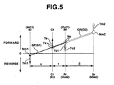
- FIG. 5 is a lever diagram showing a state in which the hybrid transmission of FIG. 2 operates in a high speed range.
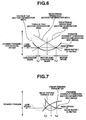
- FIG. 6 is a characteristic diagram showing torques, and rotational speeds of, and a power passing through, first and second motor/generators of the hybrid transmission of FIG. 2 , with respect to a gear ratio.
- FIG. 7 is a characteristic diagram showing a distribution of the driving torque to a front axle and a rear axle, with respect to the gear ratio, in the hybrid transmission of FIG. 2 .
- FIG. 8 is a schematic diagram showing a longitudinal sectional view of a hybrid transmission in accordance with a second embodiment of the present invention.
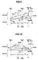
- FIG. 9 is a lever diagram showing a state in which the hybrid transmission of FIG. 8 operates in a medium speed range.
- FIG. 10 is a lever diagram showing a state in which the hybrid transmission of FIG. 8 operates in a low speed range.
- FIG. 11 is a lever diagram showing a state in which the hybrid transmission of FIG. 8 operates in a high speed range.
- FIG. 12 is a characteristic diagram showing torques, and rotational speeds of, and a power passing through, first and second motor/generators of the hybrid transmission of FIG. 8 , with respect to a gear ratio.
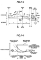
- FIG. 13 is a lever diagram equivalent to those of FIGS. 9 through 11 , showing definition of variables used in analysis of balances of rotational speeds and torques.
- FIG. 14 is a characteristic diagram showing a distribution of the driving torque to a front axle and a rear axle, with respect to a gear ratio, in the hybrid transmission of FIG. 8 .
- FIG. 15 is a schematic diagram showing a longitudinal sectional view of a hybrid transmission in accordance with a third embodiment of the present invention.
- FIG. 16 is a lever diagram showing a state in which the hybrid transmission of FIG. 15 operates in a medium speed range.
- FIG. 17 is a lever diagram showing a state in which the hybrid transmission of FIG. 15 operates in a low speed range.
- FIG. 18 is a lever diagram showing a state in which the hybrid transmission of FIG. 15 operates in a high speed range.
- FIG. 19 is a characteristic diagram showing torques, and rotational speeds of, and a power passing through, first and second motor/generators of the hybrid transmission of FIG. 15 , with respect to a gear ratio.
- FIG. 1 is a schematic diagram depicting a front-engine, four-wheel drive hybrid vehicle mounting thereon a hybrid transmission 1, and a control system of hybrid transmission 1, in accordance with an embodiment of the present invention.
- FIG. 2 shows a detailed presentation of the structure of hybrid transmission 1.
- hybrid transmission 1 includes a transmission housing 11 formed into a tubular shape.
- Transmission housing 11 houses two planetary gearsets in a rear section located far from an engine ENG in the axial direction (on the right side in the horizontal direction in FIG. 2 ). More specifically, a front planetary gearset GF is mounted nearer to engine ENG, and a rear planetary gearset GR is mounted farer from engine ENG. Both of the planetary gearsets are mounted coaxially with transmission housing 11.
- a pair of motor/generators such as a compound-current double-layer motor 12 is mounted coaxially with planetary gearsets GF, GR, or with transmission housing 11.
- Front planetary gearset GF is a simple planetary gearset, serving as a first differential device G1 including three major rotating members with two degrees of freedom.
- Rear planetary gearset GR is a double pinion planetary gearset, serving as a second differential device G2 including three major rotating members with two degrees of freedom. More specifically, front planetary gearset GF includes three major rotating members of a first sun gear Sf as a third rotating member, a first ring gear Rf as a second rotating member, and a first planet-pinion carrier Cf as a first rotating member.
- Rear planetary gearset GR includes three major rotating members of a second sun gear Sr as a third rotating member, a second ring gear Rr as a second rotating member, and a second planet-pinion carrier Cr as a first rotating member.
- First planet-pinion carrier Cf is rigidly coupled to second planet-pinion carrier Cr for rotation therewith.
- Rotation of engine ENG is input to an input shaft 13.
- Between input shaft 13 and second planet-pinion carrier Cr is selectively connected an engine clutch Cin.
- First ring gear Rf is connected to a tubular first output shaft Out1 mounted coaxially with input shaft 13 and extending outward through the rear end of transmission housing 11.
- Second ring gear Rr is connected to a second output shaft Out2 extending through the bore of first output shaft Out1 and outward through the rear end of transmission housing 11.
- an output clutch Cout Between' first output shaft Out1 and second output shaft Out2 is selectively connected an output clutch Cout, to regulate the relative rotation between them to zero.
- Compound-current double-layer motor 12 includes a pair of rotors including an inner rotor 12ri and an outer rotor 12ro of an annular shape surrounding inner rotor 12ri each coaxially and rotatably supported on a front section of transmission housing 11, and a stator 12s fixed with reference to transmission housing 11 and disposed in an annular space defined between inner rotor 12ri and outer rotor 12ro.
- stator 12s and inner rotor 12ri serve for a first motor/generator MG1
- stator 12s and outer rotor 12ro serve for a second motor/generator MG2.
- Motor/generators MG1, MG2 each function as a motor that during a compound current being supplied, outputs a rotational speed (including zero) in a direction in accordance with the supplied current, or each function as a generator that during an external torque being applied, outputs a power in accordance with a rotational speed by the external torque.
- First motor/generator MG1 (or inner rotor 12ri) is connected to first sun gear Sf.
- Second motor/generator MG2 (or outer rotor 12ro) is connected to second sun gear Sr.
- hybrid transmission 1 is mounted in a longitudinal position coaxially with, and on the rear end of, engine ENG, as shown in FIG. 1 .
- First output shaft Out1 is drivingly connected to left and right front wheels 32L and 32R via a front differential gear mechanism 31.
- Second output shaft Out2 is drivingly connected to left and right rear wheels 35L and 35R via a propeller shaft 33 and a rear differential gear mechanism 34.
- the control system includes a hybrid controller 21 to integrally control engine ENG and hybrid transmission 1 (including motor/generators MG1, MG2). More specifically, hybrid controller 21 issues a command to an engine controller 22 to adjust output torque Te of engine ENG to a target torque. Hybrid controller 21 also issues commands to a motor/generator controller 23 to adjust output torques Tm1, Tm2 of motor/generators MG1, MG2 to target torques. Motor/generator controller 23 controls motor/generators MG1, MG2 via an inverter 24 and via a battery 25 to adjust output torques Tm1, Tm2 to target torques.
- hybrid controller 21 issues a signal Scb to hybrid transmission 1 to selectively engage and release torque-transmitting mechanisms such as an engine clutch Cin and an output clutch Cout (and a brake in another embodiment).
- Hybrid transmission 1 selectively engages and releases engine clutch Cin and output clutch Cout, using hydraulic pressure supplied by a hydraulic source 28, in accordance with signal Scb.
- hybrid controller 21 receives information needed to determine the control method. The information includes a signal of accelerator opening APO output from an accelerator opening sensor 26, a signal of a vehicle speed VSP output from a vehicle speed sensor 27.
- FIG. 3 shows a lever diagram in accordance with an operating state of hybrid transmission 1 of FIG. 2 .
- front planetary gearset GF as first differential device G1
- the rotational speed varies monotonously in order of first sun gear Sf, first planet-pinion carrier Cf, and first ring gear Rf.
- first sun gear Sf, first planet-pinion carrier Cf, and first ring gear Rf have an extreme rotational speed, an intermediate rotational speed, and another extreme rotational speed, among the three rotating members of front planetary gearset GF, respectively.
- rear planetary gearset GR as second differential device G2
- the rotational speed varies monotonously in order of second planet-pinion carrier Cr, second ring gear Rr, and second sun gear Sr.
- second planet-pinion carrier Cr, second ring gear Rr, and second sun gear Sr have an extreme rotational speed, an intermediate rotational speed, and another extreme rotational speed, among the three rotating members of rear planetary gearset GR, respectively.
- First planet-pinion carrier Cf and second planet-pinion carrier Cr are coupled to each other.
- First ring gear Rf is connected to first output shaft Out1
- second ring gear Rr is connected to second output shaft Out2.
- Output clutch Cout selectively connects and disconnects first output shaft Out1 and second output shaft Out2, to establish and to release a differential lock.
- First sun gear Sf is connected to first motor/generator MG1 (or inner rotor 12ri).
- Second planet-pinion carrier Cr is connected to an input In from engine ENG (or input shaft 13) via engine clutch Cin.
- Second sun gear Sr is connected to second motor/generator MG2 (or outer rotor 12ro).
- the lever diagram as shown in FIG. 3 represents an operating state of hybrid transmission 1. Relative distances between the rotating members along the horizontal axis of the lever diagram are determined by gear ratios between the rotating members of hybrid transmission 1. In the lever diagram, with the distance between first ring gear Rf and first planet-pinion carrier Cf (the distance between second ring gear Rr and second planet-pinion carrier Cr) set to 1 as a reference, the distance between first planet-pinion carrier Cf and first sun gear Sf is ⁇ , and the distance between second ring gear Rr and second sun gear Sr is ⁇ . Positions along the vertical axis of the lever diagram indicate rotational speeds of the rotating members. A positive position above zero indicates a forward (normal) rotation, while a negative position below zero indicates a backward (reverse) rotation.
- torques such as torques Tm1, Tm2 of motor/generators MG1, MG2, engine torque Te, and torques To1, To2 of output shafts Out1, Out2, which are imposed on the associated rotating members, are indicated by vertical vectors.
- An upward vector indicates a torque to move upward the position (to positively increase the rotational speed) of a rotating member
- a downward vector indicates a torque to move downward the position (to decrease the rotational speed) of a rotating member.
- front planetary gearset GF is indicated by lever GF (G1)
- rear planetary gearset GR is indicated by lever GR (G2).
- output shafts Out1 and Out2 rotate at a same rotational speed No
- lever GF (G1)wand lever GR (G2) are overlapped with each other to form a straight line, as shown in FIGS. 3 through 5 .
- output shafts Out1 and Out2 rotate at a same rotational speed No, so as to rotate the front and the rear wheels with no difference in the rotational speed.
- Tm ⁇ 1 - ( Nm ⁇ 2 ⁇ Te ) / Nm ⁇ 2 ⁇ ( 1 + ⁇ ) + ⁇ ⁇ Nm ⁇ 1
- Tm ⁇ 2 ( Nm ⁇ 1 ⁇ Te ⁇ i ) / Nm ⁇ 1 ⁇ ( 1 + ⁇ ) + ⁇ ⁇ Nm ⁇ 2
- To ⁇ 1 - ⁇ ⁇ Tm ⁇ 1
- To ⁇ 2 ( 1 - ⁇ ) ⁇ Tm ⁇ 2
- engine torque Te is a positive torque (driving torque) in a steady-state driving condition.
- driving torques To1, To2 are both represented by negative torques (loading torques) in a lever diagram, because reaction forces from the road surface is imposed on hybrid transmission 1 in the opposite direction of driving torques To1, To2.
- torque Tm1 needs to be a negative torque or a generator torque biasing rotational speed Nm1 of first motor/generator MG1 downward toward zero.
- torque Tm2 needs to be a positive torque or a motor torque biasing rotational speed Nm2 of second motor/generator MG2 upward away from zero.
- first motor/generator MG1 functions as a generator
- second motor/generator MG2 functions as a motor.
- second motor/generator MG2 can be energized with a power generated by first motor/generator MG1, to keep the balances of rotational speeds and torques of the levers, in other words, to keep stable the operating state of hybrid transmission 1 as indicated by lever GF (G1) and lever GR (G2). If the operating state of hybrid transmission 1 is not retained without power supply from battery 25, the power balance between motor/generators MG1, MG2 is slightly shifted (Pb ⁇ 0) to keep the operating state of hybrid transmission 1.
- torque Tm1 of first motor/generator MG1 connected to first sun gear Sf, and torque Tm2 of second motor/generator MG2 connected to second sun gear Sr are determined so as to balance lever GF (G1) and lever GR (G2). More specifically, torque Tm1 needs to be a negative torque or a generator torque biasing rotational speed Nm1 of first motor/generator MG1 downward toward zero. On the other hand, torque Tm2 needs to be a positive torque or a generator torque biasing rotational speed Nm2 of second motor/generator MG2 upward toward zero.
- first motor/generator MG1 and second motor/generator MG2 both function as a generator, to store the generated electric power in battery 25, and to keep the balances of rotational speeds and torques of the levers, in other words, to keep stable the operating state of hybrid transmission 1 as indicated by lever GF (G1) and lever GR (G2).
- torque Tm1 of first motor/generator MG1 connected to first sun gear Sf, and torque Tm2 of second motor/generator MG2 connected to second sun gear Sr are determined so as to balance lever GF (G1) and lever GR (G2). More specifically, torque Tm1 needs to be a negative torque or a motor torque biasing rotational speed Nm1 of first motor/generator MG1 downward away from zero. On the other hand, torque Tm2 needs to be a positive torque or a motor torque biasing rotational speed Nm2 of second motor/generator MG2 upward away from zero.
- first motor/generator MG1 and second motor/generator MG2 both function as a motor, consuming the electric power in battery 25, to keep the balances of rotational speeds and torques of the levers, in other words, to keep stable the operating state of hybrid transmission 1 as indicated by lever GF (G1) and lever GR (G2).
- the variables include rotational speeds Nm1, Nm2 and torques Tm1, Tm2 of motor/generators MG1, MG2, and a power passing through first motor/generator MG1.
- the power passing through second motor/generator MG2 has a sign opposite to and a same magnitude as the power passing through first motor/generator MG1.
- Passing power P is zero, at a gear ratio i L at which rotational speed Nm2 of second motor/generator MG2 is zero and torque Tm1 of first motor/generator MG1 is zero, and at a gear ratio i H at which torque Tm2 of second motor/generator MG2 is zero and rotational speed Nm1 of first motor/generator MG1 is zero.
- the variables include driving torques To1, To2 of output shafts Out1, Out2, and passing power P.
- the operating state of hybrid transmission 1 shown in FIG. 3 is in the medium speed range with a gear ratio between gear ratios i L and i H .
- second motor/generator MG2 is energized by first motor/generator MG1, to retain stable the operating state of hybrid transmission 1 without power supply from battery 25.
- the operating state of hybrid transmission 1 shown in FIG. 4 is in the low speed range with a gear ratio higher than gear ratio i L .
- first motor/generator MG1 and second motor/generator MG2 both function as a generator, to retain stable the operating state of hybrid transmission 1 without power supply from battery 25.
- torque Tm2 of second motor/generator MG2 or rotational speed Nm1 of first motor/generator MG1 needs to be large.
- Motor/generators MG1, MG2 needs to be upsized to satisfy this requirement.
- the operating state of hybrid transmission 1 shown in FIG. 5 is in the high speed range with a gear ratio lower than gear ratio i H .
- first motor/generator MG1 and second motor/generator MG2 both function as a motor, to retain stable the operating state of hybrid transmission 1 without power supply from battery 25.
- torque Tm1 of first motor/generator MG1 or rotational speed Nm2 of second motor/generator MG2 needs to be large.
- Motor/generators MG1, MG2 needs to be upsized to satisfy this requirement.
- gear ratios i L and i H In the speed range between gear ratios i L and i H , the operating state of hybrid transmission 1 is retained stable without power supply from battery 25, resulting in downsizing of battery 25.
- rotational speeds Nm1, Nm2, and torques Tm1, Tm2, of motor/generators MG1, MG2 are small, as shown in FIG. 6 , resulting in downsizing of motor/generators MG1, MG2. Therefore, a gear ratio between gear ratios i L and i H is employed in a normal driving condition. Gear ratios out of this range may be employed unless desired rotational speeds and torques exceed the capacity of motor/generators MG1, MG2.
- hybrid transmission 1 With the gear ratio between gear ratio i L and gear ratio i H , hybrid transmission 1 employs a front drive mode in accordance with a higher gear ratio, and a rear drive mode or a four-wheel drive mode in accordance with a lower gear ratio. In this manner, hybrid transmission 1 provides a preferable distribution of the driving torque with respect to the gear ratio.
- front and rear driving torques are output from first ring gear Rf and second ring gear Rr of via output shafts Out1, Out2. Accordingly, four-wheel drive mode is achieved without an additional motor. This allows using a typical vehicle floor as a four-wheel drive hybrid vehicle.
- hybrid transmission 1 An arbitrary operating state of hybrid transmission 1 is retained stable by controlling motor/generators MG1, MG2, and engine ENG. Accordingly, driving torques To1, To2 of output shafts Out1, Out2 are determined as desired, so that there is no difference in the ability of driving wheels between front and rear driving axles. Therefore, this hybrid transmission bears a great flexibility in distribution of driving torque.
- Hybrid transmission 1 includes front planetary gearset GF, rear planetary gearset GR, and a central planetary gearset GC mounted coaxially with and between front planetary gearset GF and rear planetary gearset GR.
- Front planetary gearset GF is a double-pinion planetary gearset, serving as a first differential device G1 including three major rotating members with two degrees of freedom.
- Rear planetary gearset GR is a simple planetary gearset, serving as a second differential device G2 including three major rotating members with two degrees of freedom.
- Central planetary gearset GC is a simple planetary gearset, serving as a third differential device G3 including three major rotating members with two degrees of freedom. More specifically, front planetary gearset GF includes three major rotating members of a first sun gear Sf as a third rotating member, a first ring gear Rf as a second rotating member, and a first planet-pinion carrier Cf as a first rotating member. Rear planetary gearset GR includes three major rotating members of a second sun gear Sr as a first rotating member, a second ring gear Rr as a third rotating member, and a second planet-pinion carrier Cr as a second rotating member.
- Central planetary gearset GC includes three major rotating members of a third sun gear Sc, a third ring gear Rc, and a third planet-pinion carrier Cc. Rotation of engine ENG is input to input shaft 13. Between input shaft 13 and second ring gear Rr is selectively connected engine clutch Cin.
- First ring gear Rf is connected to a tubular first output shaft Out1 mounted coaxially with input shaft 13 and extending outward through the rear end of transmission housing 11.
- Second planet-pinion carrier Cr is connected to a second output shaft Out2 extending through the bore of first output shaft Out1 and outward through the rear end of transmission housing 11.
- an output clutch Cout Between first output shaft Out1 and second output shaft Out2 is selectively connected an output clutch Cout, to regulate the relative rotation between them to zero.
- Hybrid transmission 1 includes compound-current double-layer motor 12 as shown in FIG. 2 .
- stator 12s and outer rotor 12ro serve for a first motor/generator MG1
- stator 12s and inner rotor 12ri serve for a second motor/generator MG2.
- First motor/generator MG1 (or outer rotor 12ro) is connected to first sun gear Sf.
- Second motor/generator MG2 (or inner rotor 12ri) is connected to third sun gear Sc.
- Third sun gear Sc is rigidly connected to first planet-pinion carrier Cf.
- Third ring gear Rc is rigidly connected to second sun gear Sr.
- Third planet-pinion carrier Cc is selectively held against rotation by brake B.
- FIG. 9 shows a lever diagram in accordance with an operating state of hybrid transmission 1 of FIG. 8 .
- front planetary gearset GF as first differential device G1
- the rotational speed varies monotonously in order of first sun gear Sf, first ring gear Rf, and first planet-pinion carrier Cf.
- first sun gear Sf, first ring gear Rf, and first planet-pinion carrier Cf have an extreme rotational speed, an intermediate rotational speed, and another extreme rotational speed, among the three rotating members of front planetary gearset GF, respectively.
- rear planetary gearset GR as second differential device G2
- the rotational speed varies monotonously in order of second ring gear Rr, second planet-pinion carrier Cr, and second sun gear Sr.
- second ring gear Rr, second planet-pinion carrier Cr, and second sun gear Sr have an extreme rotational speed, an intermediate rotational speed, and another extreme rotational speed, among the three rotating members of rear planetary gearset GR, respectively.
- rotational speed varies monotonously in order of third sun gear Sc, third planet-pinion carrier Cc, and third ring gear Rc.
- third sun gear Sc, third planet-pinion carrier Cc, and third ring gear Rc have an extreme rotational speed, an intermediate rotational speed, and another extreme rotational speed, among the three rotating members of central planetary gearset GC, respectively:
- First ring gear Rf is connected to first output shaft Out1
- second planet-pinion carrier Cr is connected to second output shaft Out2.
- Output clutch Cout selectively connects and disconnects first output shaft Out1 and second output shaft Out2, to establish and to release a differential lock.
- First sun gear Sf is connected to first motor/generator MG1 (or outer rotor 12ro).
- Second ring gear Rr is connected to an input In from engine ENG (or input shaft 13) via engine clutch Cin.
- Third sun gear Sc is connected to second motor/generator MG2 (or inner rotor 12ri). Second sun gear Sr is connected to third ring gear Rc. First planet-pinion carrier Cf is connected to third sun gear Sc. Third planet-pinion carrier Cc is held against rotation by brake B. In this manner, the difference in the rotational speed between second sun gear Sr and first planet-pinion carrier Cf is controlled. In other words, first planet-pinion carrier Cf is connected to second sun gear Sr for reverse rotation.
- Central planetary gearset GC serves as the reverse connection.
- the lever diagram as shown in FIG. 9 represents an operating state of hybrid transmission 1. Relative distances between the rotating members along the horizontal axis of the lever diagram are determined by gear ratios between the rotating members of hybrid transmission 1.
- the distance between second ring gear Rr and second planet-pinion carrier Cr set to 1 as a reference the distance between second ring gear Rr and first sun gear Sf is ⁇
- the distance between second planet-pinion carrier Cr (first ring gear Rf) and second sun gear Sr (first planet-pinion carrier Cf) is ⁇ .
- the distance between third sun gear Sc and third planet-pinion carrier Cc set to 1 as a reference the distance between third planet-pinion carrier Cc and third ring gear Rc is ⁇ .
- a positive position above 0 indicates a forward (normal) rotation, while a negative position below 0 indicates a backward (reverse) rotation.
- torques such as torques Tm1, Tm2 of motor/generators MG1, MG2, engine torque Te, and torques To1, To2 of output shafts Out1, Out2, which are imposed on the associated rotating members, are indicated by vertical vectors.
- An upward vector indicates a torque to move upward the position (to positively increase the rotational speed) of a rotating member
- a downward vector indicates a torque to move downward the position (to decrease the rotational speed) of a rotating member.
- front planetary gearset GF is indicated by lever GF (G1)
- rear planetary gearset GR is indicated by lever GR (G2)
- central planetary gearset GC is indicated by lever GC (G3).
- output shafts Out1 and Out2 rotate at a same rotational speed No
- lever GF (G1) and lever GR (G2) intersect with each other at an angle which is produced by lever GC (G3) or by central planetary gearset GC, as shown in FIGS. 9 through 11 .
- output shafts Out1 and Out2 rotate at a same rotational speed No, so as to rotate the front and the rear wheels with no difference in the rotational speed.
- torque Tm1 needs to be a positive torque or a generator torque biasing rotational speed Nm1 of first motor/generator MG1 upward toward zero.
- torque Tm2 needs to be a positive torque or a motor torque biasing rotational speed Nm2 of second motor/generator MG2 upward away from zero.
- first motor/generator MG1 functions as a generator
- second motor/generator MG2 functions as a motor.
- second motor/generator MG2 can be energized with a power generated by first motor/generator MG1, to keep the balances of rotational speeds and torques of the levers, in other words, to keep stable the operating state of hybrid transmission 1 as indicated by lever GF (G1) and lever GR (G2). If the operating state of hybrid transmission 1 is not retained without power supply from battery 25, the power balance between motor/generators MG1, MG2 is slightly shifted (Pb ⁇ 0) to keep the operating state of hybrid transmission 1.
- torque Tm1 needs to be a positive torque or a motor torque biasing rotational speed Nm1 of first motor/generator MG1 upward away from zero.
- torque Tm2 needs to be a negative torque or a generator torque biasing rotational speed Nm2 of second motor/generator MG2 downward toward zero.
- first motor/generator MG1 functions as a motor
- second motor/generator MG2 functions as a generator.
- first motor/generator MG1 can be energized with a power generated by second motor/generator MG2, to keep the balances of rotational speeds and torques of the levers, in other words, to keep stable the operating state of hybrid transmission 1 as indicated by lever GF (G1) and lever GR (G2). If the operating state of hybrid transmission 1 is not retained without power supply from battery 25, the power balance between motor/generators MG1, MG2 is slightly shifted (Pb ⁇ 0) to keep the operating state of hybrid transmission 1.
- torque Tm1 of first motor/generator MG1 connected to first sun gear Sf, and torque Tm2 of second motor/generator MG2 connected to third sun gear Sc and first planet-pinion carrier Cf, are determined so as to balance lever GF (G1) and lever GR (G2). More specifically, torque Tm1 needs to be a negative torque or a generator torque biasing rotational speed Nm1 of first motor/generator MG1 downward toward zero. On the other hand, torque Tm2 needs to be a negative torque or a motor torque biasing rotational speed Nm2 of second motor/generator MG2 upward away from zero.
- first motor/generator MG1 functions as a generator
- second motor/generator MG2 functions as a motor.
- second motor/generator MG2 can be energized with a power generated by first motor/generator MG1, to keep the balances of rotational speeds and torques of the levers, in other words, to keep stable the operating state of hybrid transmission 1 as indicated by lever GF (G1) and lever GR (G2). If the operating state of hybrid transmission 1 is not retained without power supply from battery 25, the power balance between motor/generators MG1, MG2 is slightly shifted (Pb ⁇ 0) to keep the operating state of hybrid transmission 1.
- the variables include rotational speeds Nm1, Nm2 and torques Tm1, Tm2 of motor/generators MG1, MG2, and a power passing through first motor/generator MG1.
- the power passing through second motor/generator MG2 has a sign opposite to and a same magnitude as the power passing through first motor/generator MG1.
- Passing power P is zero, at a gear ratio i L at which rotational speed Nm2 of second motor/generator MG2 is zero and torque Tm1 of first motor/generator MG1 is zero, and at a gear ratio i H at which torque Tm2 of second motor/generator MG2 is zero and rotational speed Nm1 of first motor/generator MG1 is zero.
- the variables include driving torques To1, To2 of output shafts Out1, Out2, and passing power P.
- the operating state of hybrid transmission 1 shown in FIG. 9 is in the low speed range with a gear ratio higher than gear ratio i L .
- the operating state of hybrid transmission 1 shown in FIG. 10 is in the medium speed range with a gear ratio between gear ratios i L and i H .
- the operating state of hybrid transmission 1 shown in FIG. 11 is in the high speed range with a gear ratio lower than gear ratio i H .
- second motor/generator MG2 is energized by first motor/generator MG1, to retain stable the operating state of hybrid transmission 1 without power supply from battery 25. Therefore, the capacity of battery 25 may be small.
- hybrid transmission 1 of this embodiment operates in a wider speed range than that of the first embodiment.
- the operating state of hybrid transmission 1 is retained stable without power supply from battery 25, resulting in downsizing of battery 25.
- rotational speeds Nm1, Nm2, and torques Tm1, Tm2, of motor/generators MG1, MG2 are small, as shown in FIG. 12 , resulting in downsizing of motor/generators MG1, MG2. Therefore, it is preferable that a gear ratio between gear ratios i L and i H is employed in a normal driving condition. Gear ratios out of this range may be employed unless desired rotational speeds and torques exceed the capacity of motor/generators MG1, MG2.
- hybrid transmission 1 With the gear ratio between gear ratio i L and gear ratio i H , hybrid transmission 1 employs a four-wheel drive mode in accordance with a lower speed where a large driving force is needed, and a rear-wheel drive mode in accordance with a lower gear ratio. Thus, hybrid transmission 1 automatically selects a driving mode suitable for a driving condition.
- front and rear driving torques are output from first ring gear Rf and second ring gear Rr of via output shafts Out1, Out2. Accordingly, four-wheel drive mode is achieved without an additional motor. This allows using a typical vehicle floor as a four-wheel drive hybrid vehicle.
- hybrid transmission 1 An arbitrary operating state of hybrid transmission 1 is retained stable by controlling motor/generators MG1, MG2, and engine ENG. Accordingly, driving torques To1, To2 of output shafts Out1, Out2 are determined as desired, so that there is no difference in the ability of driving wheels between front and rear driving axles. Therefore, this hybrid transmission bears a great flexibility in distribution of driving torque. As discussed above, this feature is provided in all the speed ranges.
- Hybrid transmission 1 includes front double-pinion planetary gearset GF as first differential device G1, rear simple planetary gearset GR as second differential device G2, and central simple planetary gearset GC as third differential device G3 mounted coaxially with and between front planetary gearset GF and rear planetary gearset GR, as in the second embodiment as shown in FIG. 8 .
- Planetary gearsets GF, GR, and GC include rotating members connected to input shaft 13, output shafts Out1, Out2, and motor/generators MG1, MG2, as in the second embodiment as shown in FIG. 8 .
- hybrid transmission 1 includes a mode clutch Cm selectively connected between third ring gear Rc and third planet-pinion carrier Cc.
- mode clutch Cm is constantly engaged so that the all major rotating members of central planetary gearset GC rotate solidly with each other.
- brake B is constantly released.
- central planetary gearset GC is configured to rotate solidly with second sun gear Sr and with first planet-pinion carrier Cf.
- FIG. 16 shows a lever diagram in accordance with an operating state of hybrid transmission 1 of FIG. 15 .
- lever GC G3
- the operating state of hybrid transmission 1 as discussed below is determined by controlling second motor/generator MG2 to move up or down lever GC (G3), or by controlling first motor/generator MG1 to move up or down the point of first sun gear Sf.
- output shafts Out1 and Out2 rotate at a same rotational speed No
- lever GF (G1) and lever GR (G2) are overlapped with each other to form a straight line, as shown in FIG. 3 .
- output shafts Out1 and Out2 rotate at a same rotational speed No, so as to rotate the front and the rear wheels with no difference in the rotational speed.
- torque Tm1 needs to be a positive torque or a motor torque biasing rotational speed Nm1 of first motor/generator MG1 upward away from zero.
- torque Tm2 needs to be a positive torque or a generator torque biasing rotational speed Nm2 of second motor/generator MG2 upward toward zero.
- first motor/generator MG1 functions as a motor
- second motor/generator MG2 functions as a generator.
- first motor/generator MG1 can be energized with a power generated by second motor/generator MG2, to keep the balances of rotational speeds and torques of the levers, in other words, to keep stable the operating state of hybrid transmission 1 as indicated by lever GF (G1) and lever GR (G2).
- the power balance between motor/generators MG1, MG2 is slightly shifted (Pb#0) to keep the operating state of hybrid transmission 1.
- torque Tm1 of first motor/generator MG1 connected to first sun gear Sf, and torque Tm2 of second motor/generator MG2 connected to third sun gear Sc and first planet-pinion carrier Cf, are determined so as to balance lever GF (G1) and lever GR (G2). More specifically, torque Tm1 needs to be a positive torque or a generator torque biasing rotational speed Nm1 of first motor/generator MG1 upward toward zero. On the other hand, torque Tm2 needs to be a positive torque or a motor torque biasing rotational speed Nm2 of second motor/generator MG2 upward away from zero.
- first motor/generator MG1 functions as a generator
- second motor/generator MG2 functions as a motor.
- second motor/generator MG2 can be energized with a power generated by first motor/generator MG1, to keep the balances of rotational speeds and torques of the levers, in other words, to keep stable the operating state of hybrid transmission 1 as indicated by lever GF (G1) and lever GR (G2). If the operating state of hybrid transmission 1 is not retained without power supply from battery 25, the power balance between motor/generators MG1, MG2 is slightly shifted (Pb ⁇ 0) to keep the operating state of hybrid transmission 1.
- torque Tm1 needs to be a positive torque or a motor torque biasing rotational speed Nm1 of first motor/generator MG1 upward away from zero.
- torque Tm2 needs to be a positive torque or a motor torque biasing rotational speed Nm2 of second motor/generator MG2 upward away from zero.
- first motor/generator MG1 and second motor/generator MG2 both function as a motor, consuming the electric power in battery 25, to keep the balances of rotational speeds and torques of the levers, in other words, to keep stable the operating state of hybrid transmission 1 as indicated by lever GF (G1) and lever GR (G2).
- the variables include rotational speeds Nm1, Nm2 and torques Tm1, Tm2 of motor/generators MG1, MG2, and a power passing through first motor/generator MG1.
- the power passing through second motor/generator MG2 has a sign opposite to and a same magnitude as the power passing through first motor/generator MG1.
- Passing power P is zero, at a gear ratio i L at which rotational speed Nm2 of second motor/generator MG2 is zero and torque Tm1 of first motor/generator MG1 is zero, and at a gear ratio i H at which torque Tm2 of second motor/generator MG2 is zero and rotational speed Nm1 of first motor/generator MG1 is zero.
- the operating state of hybrid transmission 1 shown in FIG. 16 is in the low speed range with a gear ratio higher than gear ratio i L .
- the operating state of hybrid transmission 1 shown in FIG. 17 is in the high speed range with a gear ratio lower than gear ratio i H .
- the operating state of hybrid transmission 1 shown in FIG. 18 is in the medium speed range with a gear ratio between gear ratios i L and i H .
- one motor/generator is energized by the other motor/generator, to retain stable the operating state of hybrid transmission 1 without power supply from battery 25. Therefore, the capacity of battery 25 may be small.
- hybrid transmission 1 In the medium speed range with a gear ratio between gear ratios i L and i H , the operating state of hybrid transmission 1 is retained stable by consuming electric power in battery 25. In this rage, however, rotational speeds Nm1, Nm2, and torques Tm1, Tm2, of motor/generators MG1, MG2 are small, as shown in FIG. 19 , resulting in downsizing of motor/generators MG1, MG2.
- Which range of gear ratio is employed is determined based on which is regarded as important the downsizing of battery 25 or the downsizing of motor/generators MG1, MG2.
- Hybrid transmission 1 may be operate in as wide gear ratio range as possible, unless desired rotational speeds and torques exceed the capacity of motor/generators MG1, MG2.
- front and rear driving torques are output from first ring gear Rf and second ring gear Rr of via output shafts Out1, Out2. Accordingly, four-wheel drive mode is achieved without an additional motor. This allows using a typical vehicle floor as a four-wheel drive hybrid vehicle.
- hybrid transmission 1 An arbitrary operating state of hybrid transmission 1 is retained stable by controlling motor/generators MG1, MG2, and engine ENG. Accordingly, driving torques To1, To2 of output shafts Out1, Out2 are determined as desired, so that there is no difference in the ability of driving wheels between front and rear driving axles. Therefore, this hybrid transmission bears a great flexibility in distribution of driving torque.
- hybrid transmission 1 includes a tubular first output shaft Out1 extending outward through the rear end of transmission housing 11, and a second output shaft Out2 extending through the bore of first output shaft Out1 and outward through the rear end of transmission housing 11, to output driving power through two drive paths from a same portion of hybrid transmission 1.
- first output shaft Out1 may be connected to a front axle
- second output shaft Out2 may be connected to a rear axle.
- sharing a stator, layered first and second motor/generators MG1, MG2 are coaxially mounted between engine ENG and front planetary gearset GF. Mounting two motor/generators MG1, MG2 in this manner makes hybrid transmission 1 compact so that mountability of hybrid transmission 1 is enhanced.
Landscapes
- Engineering & Computer Science (AREA)
- Mechanical Engineering (AREA)
- Chemical & Material Sciences (AREA)
- Combustion & Propulsion (AREA)
- Transportation (AREA)
- General Engineering & Computer Science (AREA)
- Hybrid Electric Vehicles (AREA)
- Electric Propulsion And Braking For Vehicles (AREA)
- Arrangement And Driving Of Transmission Devices (AREA)
- Arrangement Of Transmissions (AREA)
- Motor Power Transmission Devices (AREA)
- Retarders (AREA)
- Structure Of Transmissions (AREA)
Claims (16)
- Hybridgetriebe für ein Hybridfahrzeug, in dem drei Motoren montiert sind, enthaltend eine Brennkraftmaschine (ENG), einen ersten Elektromotor / Generator (MG1) und einen zweiten Elektromotor / Generator (MG2), wobei das Hybridgetriebe aufweist:eine erste Ausgangswelle (Out1);eine zweite Ausgangswelle (Out2);eine erste Differentialvorrichtung (G1) mit zwei Freiheitsgraden, enthaltend ein erstes Drehteil (Cf), ein zweites Drehteil (Rf) und eine drittes Drehteil (Sf);eine zweite Differentialvorrichtung (G2) mit zwei Freiheitsgraden, enthaltend ein erstes Drehteil (Cr; Sr), ein zweites Drehteil (Rr; Cr) und eine drittes Drehteil (Sr; Rr);das erste Drehteil (Cf) der ersten Differentialvorrichtung (G1), verbunden mit dem ersten Drehteil (Cr; Sr) der zweiten Differentialvorrichtung (G2) und mit einem ersten der drei Motoren (ENG; MG2);das zweite Drehteil (Rf) der ersten Differentialvorrichtung (G1), verbunden mit der ersten Ausgangswelle (Out1);das zweite Drehteil (Rr; Cr) der zweiten Differentialvorrichtung (G2), verbunden mit der zweiten Ausgangswelle (Out2);das dritte Drehteil (Sr; Rr) der ersten Differentialvorrichtung (G1), verbunden mit einem zweiten der drei Motoren (MG1); unddas dritte Drehteil (Sr; Rr) der zweiten Differentialvorrichtung (G2), verbunden mit einem dritten der drei Motoren (MG2; ENG).
- Hybridgetriebe nach Anspruch 1, wobei:das erste Drehteil (Cf) der ersten Differentialvorrichtung (G1) eine Zwischendrehzahl unter den drei Drehteilen der ersten Differentialvorrichtung (G1) hat;das erste Drehteil (Cr) der zweiten Differentialvorrichtung (G2) eine extreme Drehzahl unter den drei Drehteilen der zweiten Differentialvorrichtung (G2) hat;das zweite Drehteil (Rf) der ersten Differentialvorrichtung (G1) eine extreme Drehzahl unter den drei Drehteilen der ersten Differentialvorrichtung (G1) hat;das zweite Drehteil (Rr) der zweiten Differentialvorrichtung (G2) eine Zwischendrehzahl unter den drei Drehteilen der zweiten Differentialvorrichtung (G2) hat;das dritte Drehteil (Sf) der ersten Differentialvorrichtung (G1) eine weitere extreme Drehzahl unter den drei Drehteilen der ersten Differentialvorrichtung (G1) hat;das dritte Drehteil (Rr) der zweiten Differentialvorrichtung (G2) eine weitere extreme Drehzahl unter den drei Drehteilen der zweiten Differentialvorrichtung (G2) hat;der erste Motor die Brennkraftmaschine (ENG) ist;der zweite Motor der erste Elektromotor / Generator (MG1) ist; undder dritte Motor der zweite Elektromotor / Generator (MG2) ist.
- Hybridgetriebe nach Anspruch 2, wobei:die erste Differentialvorrichtung (G1) ein einfacher Planetenradsatz ist, enthaltend ein erstes Sonnenrad (Sf), das als das dritte Drehteil dient, ein erstes Ringzahnrad (Rf), das als das zweite Drehteil dient, und einen ersten Planeten- Ritzelzahnradträger (Cf), der als das erste Drehteil dient und näher zu der Brennkraftmaschine (ENG) angeordnet ist; unddie zweite Differentialvorrichtung (G2) ein Doppel- Ritzelzahnrad- Planetenradsatz ist, der ein zweites Sonnenrad (Sr) enthält, das als das dritte Drehteil dient, ein zweites Ringzahnrad (Rr), das als das zweite Drehteil dient, und einen zweiten Planeten- Ritzelzahnradträger (Cr), der als das erste Drehteil dient und weiter entfernt von der Brennkraftmaschine (ENG) angeordnet ist.
- Hybridgetriebe nach Anspruch 2, wobei:die erste Ausgangswelle (Out1) in einer rohrförmigen Form gebildet ist, die sich nach außen durch ein hinteres Ende eines Getriebegehäuses (11) erstreckt; unddie zweite Ausgangswelle (Out2) sich durch eine Bohrung der ersten Ausgangswelle (Out1) und nach außen durch das hintere Ende des Getriebegehäuses (11) erstreckt.
- Hybridgetriebe nach Anspruch 1, wobei:das erste Drehteil (Cf) der ersten Differentialvorrichtung (G1) eine extreme Drehzahl unter den drei Drehteilen der ersten Differentialvorrichtung (G1) hat; das erste Drehteil (Sr) der zweiten Differentialvorrichtung (G2) eine extreme Drehzahl unter den drei Drehteilen der zweiten Differentialvorrichtung (G2) hat;das zweite Drehteil (Rf) der ersten Differentialvorrichtung (G1) eine Zwischendrehzahl unter den drei Drehteilen der ersten Differentialvorrichtung (G1) hat;das zweite Drehteil (Cr) der zweiten Differentialvorrichtung (G2) eine Zwischendrehzahl unter den drei Drehteilen der zweiten Differentialvorrichtung (G2) hat;das dritte Drehteil (Sf) der ersten Differentialvorrichtung (G1) eine weitere extreme Drehzahl unter den drei Drehteilen der ersten Differentialvorrichtung (G1) hat;das dritte Drehteil (Rr) der zweiten Differentialvorrichtung (G2) eine weitere extreme Drehzahl unter den drei Drehteilen der zweiten Differentialvorrichtung (G2) hat;der erste Motor der zweite Elektromotor / Generator (MG2) ist;der zweite Motor der erste Elektromotor / Generator (MG1) ist;der dritte Motor die Brennkraftmaschine (ENG) ist; unddas erste Drehteil (Cf) der ersten Differentialvorrichtung (G1) mit dem ersten Drehteil (Sr) der zweiten Differentialvorrichtung (G2) für eine Rückwärtsdrehung verbunden ist.
- Hybridgetriebe nach Anspruch 5, außerdem aufweisend eine dritte Differentialvorrichtung (G3), die als die Rückwärtsverbindung dient, die das erste Drehteil (Cf) der ersten Differentialvorrichtung (G1) und das erste Drehteil (Sr) der zweiten Differentialvorrichtüng (G2) für eine Rückwärtsdrehung verbindet.
- Hybridgetriebe nach Anspruch 6, wobei:die erste Differentialvorrichtung (G1) ein Doppel- Ritzelzahnrad- Planetenradsatz ist, der ein erstes Sonnenrad (Sf) enthält, das als das dritte Drehteil dient, ein erstes Ringzahnrad (Rf), das als das zweite Drehteil dient, und einen ersten Planeten- Ritzelzahnradträger (Cf), der als das erste Drehteil dient und näher zu der Brennkraftmaschine (ENG) angeordnet ist;die zweite Differentialvorrichtung (G2) ein einfacher Planetenradsatz ist, der ein zweites Sonnenrad (Sr) enthält, das als das erste Drehteil dient, ein zweites Ringzahnrad (Rr), das als das dritte Drehteil dient, und einen zweiten Planeten- Ritzelzahnradträger (Cr), der als das zweite Drehteil dient und weiter entfernt von der Brennkraftmaschine (ENG) angeordnet ist;die dritte Differentialvorrichtung (G3) ein einfacher Planetenradsatz ist, enthalttend ein drittes Sonnenrad (Sc), ein drittes Ringzahnrad (Rc) und einen dritten Planeten- Ritzelzahnradträger (Cc) und unter der ersten Differentialvorrichtung (G1) und der zweiten Differentialvorrichtung (G2) angeordnet ist, der erste Planeten- Ritzelzahnradträger (Cf) mit dem dritten Sonnenrad (Sc) verbunden ist;das zweite Sonnenrad (Sr) mit dem dritten Ringzahnrad (Rc) verbunden ist; undder dritte Planeten- Ritzelzahnradträger (Cc) gegen die Drehung gehalten ist.
- Hybridgetriebe nach Anspruch 7, außerdem aufweisend eine Bremse (B), die wahlweise den dritten Planeten- Ritzelzahnradträgers (Cc) gegen Drehung festlegt.
- Hybridgetriebe nach Anspruch 1, wobei:das erste Drehteil (Cf) der ersten Differentialvorrichtung (G1) eine extreme Drehzahl unter den drei Drehteilen der ersten Differentialvorrichtung (G1) hat;das erste Drehteil (Sr der zweiten Differentialvorrichtung (G2) eine extreme Drehzahl unter den drei Drehteilen der zweiten Differentialvorrichtung (G2) hat;das zweite Drehteil (Rf) der ersten Differentialvorrichtung (G1) eine Zwischendrehzahl unter den drei Drehteilen der ersten Differentialvorrichtung (G1) hat;das zweite Drehteil (Cr) der zweiten Differentialvorrichtung (G2) eine Zwischendrehzahl unter den drei Drehteilen der zweiten Differentialvorrichtung (G2) hat;das dritte Drehteil (Sf) der ersten Differentialvorrichtung (G1) eine weitere extreme Drehzahl unter den drei Drehteilen der ersten Differentialvorrichtung (G1) hat;das dritte Drehteil (Rf) der zweiten Differentialvorrichtung (G2) eine Zwischendrehzahl eine weitere extreme Drehzahl unter den drei Drehteilen der zweiten Differentialvorrichtung (G2) hat;der erste Motor der zweite Elektromotor / Generator (MG2) ist;der zweite Motor der erste Elektromotor / Generator (MG1) ist;der dritte Motor die Brennkraftmaschine (ENG) ist; unddas erste Drehteil (Cf) der ersten Differentialvorrichtung (G1) mit dem ersten Drehteil (Sr) der zweiten Differentialvorrichtung (G2) für eine feste Drehung Mit diesem verbunden ist.
- Hybridgetriebe nach Anspruch 9, außerdem aufweisend eine dritte Differentialvorrichtung (G3), die als die Verbindung dient, die das erste Drehteil (Cf) der ersten Differentialvorrichtung (G1) mit dem ersten Drehteil (Sr) der zweiten Differentialvorrichtung (G2) für eine feste Drehung mit diesem verbindet.
- Hybridgetriebe nach Anspruch 10, wobei:die erste Differentialvorrichtung (G1) ein Doppel- Ritzelzahnrad- Planetenradsatz ist, enthaltend ein erstes Sonnenrad (Sf), das als das dritte Drehteil dient,ein erstes Ringzahnrad (Rf), das als das zweite Drehteil dient, und einen zweiter Planeten- Ritzelzahnradträger (Cf), der als das erste Drehteil dient und näher zu der Brennkraftmaschine (ENG) angeordnet ist;die zweite Differentialvorrichtung (G2) ein einfacher Planetenradsatz ist, enthaltend ein zweites Sonnenrad (Sr), das als das erste Drehteil dient, ein zweites Ringzahnrad (Rr), das als das dritte Drehteil dient, und einen zweiten Planeten- Ritzelzahnradträger (Cf), der als das zweite Drehteil dient und weiter entfernt von der Brennkraftmaschine (ENG) angeordnet ist;die dritte Differentialvorrichtung (G3) ein einfacher Planetenradsatz ist, enthaltend ein drittes Sonnenrad (Sc), ein drittes Ringzahnrad (Rc) und einen dritten Planeten- Ritzelzahnradträger (Cc) und der zwischen der ersten Differentialvorrichtung (G1) und der zweiten Differentialvorrichtung (G2) angeordnet ist;der erste Planeten- Ritzelzahnradträger (Cf) mit dem dritten Sonnenrad (Sc) verbunden ist;das zweite Sonnenrad (Sr) mit dem dritten Ringzahnrad (Rc) verbunden ist; undder dritte Planeten- Ritzelzahnradträger (Cc) mit dem dritten Ringzahnrad (Rc) verbunden ist.
- Hybridgetriebe nach Anspruch 11, außerdem aufweisend eine Kupplung (Cm), die wahlweise den dritten Planeten- Ritzelzahnradträger (Cc) und das dritte Ringzahnrad (Rc) verbindet.
- Hybridgetriebe nach einem der Ansprüche 1 bis 12, wobei die erste Ausgangswelle (Out1) in einer rohrförmigen Form gebildet ist, die sich nach außen durch ein hinteres Ende eines Getriebegehäuses (11) erstreckt; und die zweite Ausgangswelle (Out2) sich durch eine Bohrung der ersten Ausgangswelle (Out1) und durch das hintere Ende des Getriebegehäuses (11) erstreckt.
- Hybridgetriebe nach einem der Ansprüche 1 bis 13, wobei der erste Motor / Generator (MG1) und der zweite Motor/Generator (MG2) einstückig gebildet sind, sich einen Stator teilend.
- Hybridgetriebe nach einem der Ansprüche 1 bis 14, wobei die erste Ausgangswelle (Out1) antreibend mit einer von einer Vorderachse oder einer Hinterachse des Fahrzeuges verbunden ist; und die zweite Ausgangswelle (Out2) antreibend mit der anderen der Vorderachse oder der Hinterachse verbunden ist.
- Hybridgetriebe nach Anspruch 15, wobei die Ausgangswelle der Differentialvorrichtung, die mit der Brennkraftmaschine verbunden ist, mit der Hinterachse verbunden ist.
Applications Claiming Priority (2)
| Application Number | Priority Date | Filing Date | Title |
|---|---|---|---|
| JP2003387932A JP3864950B2 (ja) | 2003-11-18 | 2003-11-18 | ハイブリッド変速機 |
| JP2003387932 | 2003-11-18 |
Publications (3)
| Publication Number | Publication Date |
|---|---|
| EP1533165A2 EP1533165A2 (de) | 2005-05-25 |
| EP1533165A3 EP1533165A3 (de) | 2006-10-04 |
| EP1533165B1 true EP1533165B1 (de) | 2008-12-31 |
Family
ID=34431542
Family Applications (1)
| Application Number | Title | Priority Date | Filing Date |
|---|---|---|---|
| EP04026595A Not-in-force EP1533165B1 (de) | 2003-11-18 | 2004-11-09 | Hybridgetriebe |
Country Status (5)
| Country | Link |
|---|---|
| US (1) | US7322896B2 (de) |
| EP (1) | EP1533165B1 (de) |
| JP (1) | JP3864950B2 (de) |
| CN (1) | CN1308159C (de) |
| DE (1) | DE602004018728D1 (de) |
Families Citing this family (55)
| Publication number | Priority date | Publication date | Assignee | Title |
|---|---|---|---|---|
| JP4179266B2 (ja) * | 2004-11-08 | 2008-11-12 | 日産自動車株式会社 | ハイブリッド4輪駆動システム |
| JP4337800B2 (ja) | 2005-06-27 | 2009-09-30 | トヨタ自動車株式会社 | ハイブリッド車両の動力伝達装置 |
| GB0607046D0 (de) * | 2006-04-07 | 2006-05-17 | Ford Global Tech Llc | |
| US8596165B2 (en) * | 2006-06-09 | 2013-12-03 | Parker-Hannifin Corporation | Multiple gear motor drive |
| KR100756724B1 (ko) | 2006-08-10 | 2007-09-07 | 현대자동차주식회사 | 하이브리드 차량의 파워트레인 |
| US8235853B2 (en) * | 2006-10-18 | 2012-08-07 | Magna Powertrain Inc. | Hybrid transmissions with planetary gearsets |
| US7703353B2 (en) * | 2006-11-28 | 2010-04-27 | Ford Global Technologies, Llc | Drive unit connected to a transmission output for producing forward and reverse device |
| US7652447B2 (en) * | 2007-01-23 | 2010-01-26 | Gm Global Technology Operations, Inc. | Power capacitors for AC motors mounted diametrically on associated transmissions |
| DE102008056622A1 (de) * | 2008-11-10 | 2010-05-12 | Volkswagen Ag | Aktive Differentialanordnung für ein Kraftfahrzeug |
| US8143823B2 (en) * | 2008-12-19 | 2012-03-27 | Tai-Her Yang | Bidirectional different speed ratio electric motor driving device with bidirectional input |
| US20100156210A1 (en) * | 2008-12-19 | 2010-06-24 | Tai-Her Yang | Bidirectional unequal speed electric motor driven constant directional output system |
| US8143822B2 (en) * | 2008-12-19 | 2012-03-27 | Tai-Her Yang | Bidirectional unequal speed electric motor driven bidirectional output system |
| CN201541233U (zh) * | 2008-12-19 | 2010-08-04 | 杨泰和 | 双向不等速电马达恒向输出驱动系统 |
| DE102010007941B4 (de) * | 2010-02-12 | 2023-07-27 | Dr. Ing. H.C. F. Porsche Aktiengesellschaft | Hybridfahrzeug |
| US8337352B2 (en) | 2010-06-22 | 2012-12-25 | Oshkosh Corporation | Electromechanical variable transmission |
| US8813935B2 (en) * | 2011-01-12 | 2014-08-26 | Gm Global Technology Operations, Llc | Launch / disconnect clutch for P2 hybrid powertrain |
| EP2832606B1 (de) * | 2012-03-26 | 2020-05-06 | Toyota Jidosha Kabushiki Kaisha | Antriebssteuerungsvorrichtung für ein hybridfahrzeug |
| DE102012206142A1 (de) * | 2012-04-16 | 2013-10-17 | Siemens Aktiengesellschaft | Antriebsvorrichtung für einen Kraftwagen |
| SE536663C2 (sv) * | 2012-06-27 | 2014-05-06 | Scania Cv Ab | Förfarande för att bromsa ett fordon |
| FI124819B (fi) * | 2012-11-21 | 2015-02-13 | Abb Oy | Menetelmä ja laite sähkökäyttöjärjestelmän energiatehokkuuden maksimoimiseksi |
| US9132736B1 (en) | 2013-03-14 | 2015-09-15 | Oshkosh Defense, Llc | Methods, systems, and vehicles with electromechanical variable transmission |
| US9347541B2 (en) | 2013-05-30 | 2016-05-24 | GM Global Technology Operations LLC | Modular power transfer unit assembly for a vehicle |
| US9568082B2 (en) | 2014-01-30 | 2017-02-14 | Byd Company Limited | Power transmission system for vehicle and vehicle comprising the same |
| US9568081B2 (en) | 2014-01-30 | 2017-02-14 | Byd Company Limited | Power transmission system for vehicle and vehicle comprising the same |
| WO2015113411A1 (en) | 2014-01-30 | 2015-08-06 | Byd Company Limited | Power transmission system for vehicle and vehicle comprising the same |
| CN104276031B (zh) | 2014-01-30 | 2016-01-13 | 比亚迪股份有限公司 | 车辆及其驱动控制方法 |
| WO2015113412A1 (en) | 2014-01-30 | 2015-08-06 | Byd Company Limited | Power transmission system for vehicle and vehicle comprising the same |
| CN104279311B (zh) | 2014-01-30 | 2015-11-25 | 比亚迪股份有限公司 | 车辆中同步器的控制方法及车辆 |
| US9944165B2 (en) | 2014-01-30 | 2018-04-17 | Byd Company Limited | Power transmission system for vehicle and vehicle comprising the same |
| DK3100886T3 (da) | 2014-01-30 | 2022-06-27 | Byd Co Ltd | Køretøj og kraftoverføringssystem deraf |
| CN104085301A (zh) * | 2014-06-25 | 2014-10-08 | 赵会芳 | 用于燃料车与电力车双动力的后桥 |
| EP2995487B1 (de) | 2014-09-10 | 2019-02-13 | BYD Company Limited | Kraftübertragungssystem und fahrzeug damit |
| WO2016037469A1 (en) | 2014-09-10 | 2016-03-17 | Byd Company Limited | Transmission unit, power transmission system and vehicle comprising the same |
| WO2016037468A1 (en) | 2014-09-10 | 2016-03-17 | Byd Company Limited | Power transmission system and vehicle comprising the same |
| CN104608760B (zh) | 2014-10-20 | 2016-05-25 | 比亚迪股份有限公司 | 混合动力汽车及其换挡控制方法、动力传动系统 |
| US10584775B2 (en) | 2015-02-17 | 2020-03-10 | Oshkosh Corporation | Inline electromechanical variable transmission system |
| US11701959B2 (en) | 2015-02-17 | 2023-07-18 | Oshkosh Corporation | Inline electromechanical variable transmission system |
| US9650032B2 (en) | 2015-02-17 | 2017-05-16 | Oshkosh Corporation | Multi-mode electromechanical variable transmission |
| US10982736B2 (en) | 2015-02-17 | 2021-04-20 | Oshkosh Corporation | Multi-mode electromechanical variable transmission |
| US9651120B2 (en) | 2015-02-17 | 2017-05-16 | Oshkosh Corporation | Multi-mode electromechanical variable transmission |
| US12078231B2 (en) | 2015-02-17 | 2024-09-03 | Oshkosh Corporation | Inline electromechanical variable transmission system |
| US10421350B2 (en) | 2015-10-20 | 2019-09-24 | Oshkosh Corporation | Inline electromechanical variable transmission system |
| US10578195B2 (en) | 2015-02-17 | 2020-03-03 | Oshkosh Corporation | Inline electromechanical variable transmission system |
| US9656659B2 (en) | 2015-02-17 | 2017-05-23 | Oshkosh Corporation | Multi-mode electromechanical variable transmission |
| DE102015215875A1 (de) | 2015-08-20 | 2017-02-23 | Schaeffler Technologies AG & Co. KG | Kupplungseinrichtung für Hybridantrieb |
| JP6358207B2 (ja) * | 2015-09-10 | 2018-07-18 | トヨタ自動車株式会社 | ハイブリッド車両 |
| CN105799501B (zh) * | 2015-11-03 | 2018-06-19 | 陕西同力重工股份有限公司 | 分离轴式双动力混合的工程车 |
| CN105782361B (zh) * | 2016-03-25 | 2018-06-01 | 安徽江淮汽车集团股份有限公司 | 一种发电机及其增速结构 |
| JP6446425B2 (ja) * | 2016-12-20 | 2018-12-26 | 本田技研工業株式会社 | 動力装置 |
| CN107323245B (zh) * | 2017-08-15 | 2023-04-28 | 吉林省晟林汽车传动科技有限公司 | 4dht混合动力汽车变速器 |
| JP7052262B2 (ja) * | 2017-09-08 | 2022-04-12 | トヨタ自動車株式会社 | 四輪駆動車用駆動装置 |
| CN107599820A (zh) * | 2017-10-24 | 2018-01-19 | 广西玉柴机器股份有限公司 | 混合动力总成系统 |
| CN107825954A (zh) * | 2017-12-08 | 2018-03-23 | 广西玉柴机器股份有限公司 | 一种双行星排双电机同轴混合动力传动装置 |
| CN214728144U (zh) * | 2021-03-15 | 2021-11-16 | 赛格威科技有限公司 | 混合动力全地形车 |
| DE102021208644A1 (de) | 2021-08-09 | 2023-02-09 | Zf Friedrichshafen Ag | Antriebsstrang für ein Fahrzeug |
Family Cites Families (28)
| Publication number | Priority date | Publication date | Assignee | Title |
|---|---|---|---|---|
| US1984830A (en) * | 1933-05-05 | 1934-12-18 | Frank R Higley | Vehicle drive |
| FR2158000A1 (de) * | 1971-10-30 | 1973-06-08 | Berkeley Stephens Hender | |
| JPH01182649A (ja) * | 1988-01-11 | 1989-07-20 | Daikin Mfg Co Ltd | ダンパーディスク |
| US5120282A (en) * | 1990-10-16 | 1992-06-09 | Fjaellstroem Bengt | Vehicle transmission system |
| US5168946A (en) * | 1991-09-09 | 1992-12-08 | General Electric Company | Track-laying vehicle electric drive system |
| US5421216A (en) * | 1993-05-14 | 1995-06-06 | Eaton Corp | Compound transmission having hybrid single and twin countershafts |
| DE29624299U1 (de) * | 1995-05-19 | 2001-11-22 | Toyota Motor Co Ltd | Kraftübertragungsvorrichtung, sowie Fahrzeug mit Vierradantrieb mit einer derartigen Kraftübertragungsvorrichtung |
| GB2324772B (en) * | 1995-09-29 | 1999-03-17 | Fuji Heavy Ind Ltd | Drive unit for hybrid vehicle |
| DE19606771C2 (de) | 1996-02-23 | 1998-10-01 | Bayerische Motoren Werke Ag | Hybridantrieb, insbesondere für Kraftfahrzeuge |
| JPH11332019A (ja) | 1998-05-13 | 1999-11-30 | Toyota Motor Corp | 動力伝達装置およびこれを用いた四輪駆動車輌 |
| US5935035A (en) * | 1998-06-24 | 1999-08-10 | General Motors Corporation | Electro-mechanical powertrain |
| DE19909424A1 (de) | 1999-02-23 | 2000-08-24 | Peter Tenberge | Hybridgetriebe für Fahrzeuge |
| US6579201B2 (en) * | 2000-08-22 | 2003-06-17 | New Venture Gear, Inc. | Electric hybrid four-wheel drive vehicle |
| US6491599B1 (en) * | 2000-09-15 | 2002-12-10 | General Motors Corporation | Two-mode, compound-split, electro-mechanical, vehicular transmission particulary adapted for track-laying vehicles |
| US6595884B1 (en) * | 2000-11-22 | 2003-07-22 | The Timken Company | Continuous variable transmission |
| US6464608B2 (en) * | 2001-02-08 | 2002-10-15 | New Venture Gear Inc. | Transfer case for hybrid vehicle |
| US6648785B2 (en) * | 2001-12-05 | 2003-11-18 | New Venture Gear, Inc. | Transfer case for hybrid vehicle |
| JP3578451B2 (ja) | 2001-07-23 | 2004-10-20 | 日産自動車株式会社 | 駆動装置 |
| EP1279543B1 (de) | 2001-07-23 | 2006-11-29 | Nissan Motor Co., Ltd. | Hybridantriebsstrang eines Kraftfahrzeugs |
| GB0129125D0 (en) * | 2001-12-05 | 2002-01-23 | Drivetec Uk Ltd | Automotive vehicle transmission systems |
| EP1321646B1 (de) | 2001-12-21 | 2007-08-01 | Ford Global Technologies, LLC | Brennkraftmaschine |
| US6793034B2 (en) * | 2002-01-18 | 2004-09-21 | Ford Global Technologies, Llc | Wheel-end and center axle disconnects for an electric or HEV |
| JP3641243B2 (ja) | 2002-02-26 | 2005-04-20 | 日産自動車株式会社 | ハイブリッド変速機 |
| US6638195B2 (en) * | 2002-02-27 | 2003-10-28 | New Venture Gear, Inc. | Hybrid vehicle system |
| JP3614409B2 (ja) * | 2002-03-25 | 2005-01-26 | 日産自動車株式会社 | ハイブリッド変速機 |
| JP2005029063A (ja) | 2003-07-09 | 2005-02-03 | Toyota Motor Corp | ハイブリッド車の駆動装置 |
| JP3922230B2 (ja) | 2003-07-11 | 2007-05-30 | トヨタ自動車株式会社 | ハイブリッド車の駆動装置 |
| JP3823968B2 (ja) * | 2003-12-02 | 2006-09-20 | 日産自動車株式会社 | ハイブリッド変速機 |
-
2003
- 2003-11-18 JP JP2003387932A patent/JP3864950B2/ja not_active Expired - Fee Related
-
2004
- 2004-11-08 US US10/982,885 patent/US7322896B2/en not_active Expired - Fee Related
- 2004-11-09 EP EP04026595A patent/EP1533165B1/de not_active Not-in-force
- 2004-11-09 DE DE602004018728T patent/DE602004018728D1/de active Active
- 2004-11-17 CN CNB2004100947309A patent/CN1308159C/zh not_active Expired - Fee Related
Also Published As
| Publication number | Publication date |
|---|---|
| JP3864950B2 (ja) | 2007-01-10 |
| CN1308159C (zh) | 2007-04-04 |
| EP1533165A2 (de) | 2005-05-25 |
| CN1618644A (zh) | 2005-05-25 |
| EP1533165A3 (de) | 2006-10-04 |
| DE602004018728D1 (de) | 2009-02-12 |
| JP2005147319A (ja) | 2005-06-09 |
| US7322896B2 (en) | 2008-01-29 |
| US20050107199A1 (en) | 2005-05-19 |
Similar Documents
| Publication | Publication Date | Title |
|---|---|---|
| EP1533165B1 (de) | Hybridgetriebe | |
| EP1637381B1 (de) | Hybridgetriebe | |
| US8930055B2 (en) | Dual-rotor motor for electric vehicles with a continuously variable transmisssion system with planet gear and control method thereof | |
| US7256510B2 (en) | Hybrid electro-mechanical transmission with single motor/generator and method of control | |
| US7053566B2 (en) | Drive train for hybrid electric vehicle | |
| US7219757B2 (en) | Mode transfer control apparatus and method for hybrid vehicle | |
| EP1502791B1 (de) | Hybridgetriebe und Schaltmodussteuerung für ein Hybridfahrzeug | |
| EP1350651B1 (de) | Elektrisches Hybridfahrzeug | |
| EP1350650B1 (de) | Getriebeschaltvorrichtung eines Hybridfahrzeuges | |
| US6481519B1 (en) | Electric drive axle for hybrid vehicle | |
| US6378638B1 (en) | Drive axle for hybrid vehicle | |
| EP1564056B1 (de) | Schaltmodussteuerung für ein Hybridgetriebe | |
| EP1529672A2 (de) | Antriebskraftsteuerung und Vorrichtung für ein Hybridfahrzeug | |
| US10801598B2 (en) | Hybrid axle drive with torque vectoring | |
| US20020129979A1 (en) | Electric drive motor axle with integrated reduction and differential gearset | |
| EP0937600A2 (de) | Hybridantriebssystem, und hiermit versehenes Fahrzeug bzw. Fahrrad | |
| US20050115750A1 (en) | Hybrid drive unit and vehicle mounted therewith | |
| WO2006035982A2 (ja) | 車両用駆動装置 | |
| JPH11208304A (ja) | 四輪駆動車 | |
| JP3823968B2 (ja) | ハイブリッド変速機 | |
| US20230114911A1 (en) | Vehicle drive device | |
| US11958471B2 (en) | Four-wheel drive vehicle | |
| US20230226902A1 (en) | Power-split axle drive and agricultural vehicle | |
| US20240100929A1 (en) | Powertrain for electric vehicle | |
| JP2006082761A (ja) | ハイブリッド変速機 |
Legal Events
| Date | Code | Title | Description |
|---|---|---|---|
| PUAI | Public reference made under article 153(3) epc to a published international application that has entered the european phase |
Free format text: ORIGINAL CODE: 0009012 |
|
| 17P | Request for examination filed |
Effective date: 20041109 |
|
| AK | Designated contracting states |
Kind code of ref document: A2 Designated state(s): AT BE BG CH CY CZ DE DK EE ES FI FR GB GR HU IE IS IT LI LU MC NL PL PT RO SE SI SK TR |
|
| AX | Request for extension of the european patent |
Extension state: AL HR LT LV MK YU |
|
| PUAL | Search report despatched |
Free format text: ORIGINAL CODE: 0009013 |
|
| AK | Designated contracting states |
Kind code of ref document: A3 Designated state(s): AT BE BG CH CY CZ DE DK EE ES FI FR GB GR HU IE IS IT LI LU MC NL PL PT RO SE SI SK TR |
|
| AX | Request for extension of the european patent |
Extension state: AL HR LT LV MK YU |
|
| AKX | Designation fees paid |
Designated state(s): DE FR GB |
|
| GRAP | Despatch of communication of intention to grant a patent |
Free format text: ORIGINAL CODE: EPIDOSNIGR1 |
|
| RIC1 | Information provided on ipc code assigned before grant |
Ipc: B60K 6/445 20071001ALI20080516BHEP Ipc: B60K 6/52 20071001ALI20080516BHEP Ipc: B60K 6/365 20071001AFI20080516BHEP |
|
| GRAS | Grant fee paid |
Free format text: ORIGINAL CODE: EPIDOSNIGR3 |
|
| GRAS | Grant fee paid |
Free format text: ORIGINAL CODE: EPIDOSNIGR3 |
|
| GRAA | (expected) grant |
Free format text: ORIGINAL CODE: 0009210 |
|
| AK | Designated contracting states |
Kind code of ref document: B1 Designated state(s): DE FR GB |
|
| REG | Reference to a national code |
Ref country code: GB Ref legal event code: FG4D |
|
| REF | Corresponds to: |
Ref document number: 602004018728 Country of ref document: DE Date of ref document: 20090212 Kind code of ref document: P |
|
| PLBE | No opposition filed within time limit |
Free format text: ORIGINAL CODE: 0009261 |
|
| STAA | Information on the status of an ep patent application or granted ep patent |
Free format text: STATUS: NO OPPOSITION FILED WITHIN TIME LIMIT |
|
| 26N | No opposition filed |
Effective date: 20091001 |
|
| PGFP | Annual fee paid to national office [announced via postgrant information from national office to epo] |
Ref country code: DE Payment date: 20091105 Year of fee payment: 6 |
|
| PGFP | Annual fee paid to national office [announced via postgrant information from national office to epo] |
Ref country code: FR Payment date: 20091123 Year of fee payment: 6 Ref country code: GB Payment date: 20091104 Year of fee payment: 6 |
|
| GBPC | Gb: european patent ceased through non-payment of renewal fee |
Effective date: 20101109 |
|
| REG | Reference to a national code |
Ref country code: FR Ref legal event code: ST Effective date: 20110801 |
|
| REG | Reference to a national code |
Ref country code: DE Ref legal event code: R119 Ref document number: 602004018728 Country of ref document: DE Effective date: 20110601 Ref country code: DE Ref legal event code: R119 Ref document number: 602004018728 Country of ref document: DE Effective date: 20110531 |
|
| PG25 | Lapsed in a contracting state [announced via postgrant information from national office to epo] |
Ref country code: FR Free format text: LAPSE BECAUSE OF NON-PAYMENT OF DUE FEES Effective date: 20101130 |
|
| PG25 | Lapsed in a contracting state [announced via postgrant information from national office to epo] |
Ref country code: GB Free format text: LAPSE BECAUSE OF NON-PAYMENT OF DUE FEES Effective date: 20101109 |
|
| PG25 | Lapsed in a contracting state [announced via postgrant information from national office to epo] |
Ref country code: DE Free format text: LAPSE BECAUSE OF NON-PAYMENT OF DUE FEES Effective date: 20110531 |