EP1529982A1 - Articulation élastique pour la liaison entre deux pièces et amortisseur avec une telle articulation élastique - Google Patents
Articulation élastique pour la liaison entre deux pièces et amortisseur avec une telle articulation élastique Download PDFInfo
- Publication number
- EP1529982A1 EP1529982A1 EP03292757A EP03292757A EP1529982A1 EP 1529982 A1 EP1529982 A1 EP 1529982A1 EP 03292757 A EP03292757 A EP 03292757A EP 03292757 A EP03292757 A EP 03292757A EP 1529982 A1 EP1529982 A1 EP 1529982A1
- Authority
- EP
- European Patent Office
- Prior art keywords
- joint according
- friction
- elastomeric body
- joint
- reibdämpfungseinrichtung
- Prior art date
- Legal status (The legal status is an assumption and is not a legal conclusion. Google has not performed a legal analysis and makes no representation as to the accuracy of the status listed.)
- Granted
Links
Images
Classifications
-
- B—PERFORMING OPERATIONS; TRANSPORTING
- B60—VEHICLES IN GENERAL
- B60G—VEHICLE SUSPENSION ARRANGEMENTS
- B60G13/00—Resilient suspensions characterised by arrangement, location or type of vibration dampers
- B60G13/001—Arrangements for attachment of dampers
- B60G13/003—Arrangements for attachment of dampers characterised by the mounting on the vehicle body or chassis of the damper unit
-
- F—MECHANICAL ENGINEERING; LIGHTING; HEATING; WEAPONS; BLASTING
- F16—ENGINEERING ELEMENTS AND UNITS; GENERAL MEASURES FOR PRODUCING AND MAINTAINING EFFECTIVE FUNCTIONING OF MACHINES OR INSTALLATIONS; THERMAL INSULATION IN GENERAL
- F16F—SPRINGS; SHOCK-ABSORBERS; MEANS FOR DAMPING VIBRATION
- F16F1/00—Springs
- F16F1/36—Springs made of rubber or other material having high internal friction, e.g. thermoplastic elastomers
- F16F1/38—Springs made of rubber or other material having high internal friction, e.g. thermoplastic elastomers with a sleeve of elastic material between a rigid outer sleeve and a rigid inner sleeve or pin, i.e. bushing-type
- F16F1/3863—Springs made of rubber or other material having high internal friction, e.g. thermoplastic elastomers with a sleeve of elastic material between a rigid outer sleeve and a rigid inner sleeve or pin, i.e. bushing-type characterised by the rigid sleeves or pin, e.g. of non-circular cross-section
-
- F—MECHANICAL ENGINEERING; LIGHTING; HEATING; WEAPONS; BLASTING
- F16—ENGINEERING ELEMENTS AND UNITS; GENERAL MEASURES FOR PRODUCING AND MAINTAINING EFFECTIVE FUNCTIONING OF MACHINES OR INSTALLATIONS; THERMAL INSULATION IN GENERAL
- F16F—SPRINGS; SHOCK-ABSORBERS; MEANS FOR DAMPING VIBRATION
- F16F1/00—Springs
- F16F1/36—Springs made of rubber or other material having high internal friction, e.g. thermoplastic elastomers
- F16F1/38—Springs made of rubber or other material having high internal friction, e.g. thermoplastic elastomers with a sleeve of elastic material between a rigid outer sleeve and a rigid inner sleeve or pin, i.e. bushing-type
- F16F1/387—Springs made of rubber or other material having high internal friction, e.g. thermoplastic elastomers with a sleeve of elastic material between a rigid outer sleeve and a rigid inner sleeve or pin, i.e. bushing-type comprising means for modifying the rigidity in particular directions
-
- F—MECHANICAL ENGINEERING; LIGHTING; HEATING; WEAPONS; BLASTING
- F16—ENGINEERING ELEMENTS AND UNITS; GENERAL MEASURES FOR PRODUCING AND MAINTAINING EFFECTIVE FUNCTIONING OF MACHINES OR INSTALLATIONS; THERMAL INSULATION IN GENERAL
- F16F—SPRINGS; SHOCK-ABSORBERS; MEANS FOR DAMPING VIBRATION
- F16F9/00—Springs, vibration-dampers, shock-absorbers, or similarly-constructed movement-dampers using a fluid or the equivalent as damping medium
- F16F9/32—Details
- F16F9/54—Arrangements for attachment
Definitions
- the invention relates to an elastic joint for elastically coupling two components and a damper.
- the elastic joint should be under load high frequency and low amplitude (typically 250 Hz, 0.01 mm) low Rigidity values and a weak damping to provide an acoustic insulation to reach the components to be connected elastically, ie the transmission of noise, for example, by rolling the tire on a road at high speed be caused to limit.
- high frequency and low amplitude typically 250 Hz, 0.01 mm
- a weak damping to provide an acoustic insulation to reach the components to be connected elastically, ie the transmission of noise, for example, by rolling the tire on a road at high speed be caused to limit.
- low frequencies with high amplitudes typically 10 Hz and 0.5 mm
- a high degree of damping is required, so when driving over, for example, road surveys safe driving characteristics are ensured for the motor vehicle.
- viscoelastic materials but with increasing frequency a solidification of the material goes along.
- an elastic joint and a damper with an elastic To create a joint that, while maintaining low manufacturing costs vibration loads in the entire spectrum of large and small amplitudes and frequencies one has good durability, the elastic joint an acoustic decoupling guaranteed even at low frequencies and high amplitude.
- a friction damping device with the elastomer body is connected, which is formed of a material which is more rigid than that of the elastomeric body is.
- the joint according to the invention has a softer material, which causes an acoustic coupling, especially in the high frequency range, and a stiffer Material that is responsible for the sliding and static friction in the joint and wear-resistant is ensured and a low-noise friction sliding.
- the elastomeric body and the Reibdämpfungsenutter at least partially from a Be made piece of material, wherein the Reibdämpfungs observed forming part by solidifying agent is stiffened to the desired level.
- the friction damping device has at least one friction surface on, at which the elastomeric body with one of the components directly or indirectly is coupled such that at a load of small amplitude a static friction and at a Gleitreibschlupf is formed of a large amplitude load.
- the friction surface directly with a mating surface area of the component or with the elastomeric body too interconnecting joint fitting cooperate according to the invention.
- the friction damping device is structurally independent, formed of the elastomeric body separate intermediate member, which on a the region of the elastomeric body assigned to the component to be connected is firmly attached.
- the intermediate component can be cupped or layered to reduce space requirements be formed, that is, with a dimension by one over the length and depth low strength is determined.
- the friction surface of the Reibdämpfungs is provided in the respective operating conditions the Haftreibschluß or Gleitreibschlupf permits.
- the friction damping device can be used on many various locations in the joint to form at least one, preferably two or a plurality of friction surfaces, preferably four friction surfaces, be provided.
- the friction surface of the friction damping device is such designed so that when exceeding an amplitude threshold, a function transition from the Haftreibschluß in Gleitreibschlupf takes place at the friction surface pre-determinable.
- This predeterminable setting of an amplitude threshold may be due to the particular choice the friction coefficient at the friction surface and / or by the friction surface through the Elastomer body acting normal force can be realized.
- the friction surface is particularly effective, i. especially then a lot of stress energy destroyed by friction losses, if they are substantially parallel to the main direction of the Vibration load is aligned.
- this angle is at least less than 45 °, i. the predominant directional component the area corresponds to the main direction of the vibration load.
- the elastomer body is for the application of a normal force responsible in the direction of the friction surface of the Reibdämpfungs founded to the corresponding To generate static friction or sliding friction.
- This normal force preferably caused by precompression of the elastomeric body.
- the precompression is preferably only when mounting the joint either directly to the used Components or to intermediate parts, such as hinged joints realized.
- the elastomeric body of the joint with two coupling arms which are substantially opposite to each other and substantially aligned parallel to the main direction of the vibration load, and with a with provided the Reibdämpfungs worn cooperating pressure arm.
- the pressure arm is on the one hand responsible for applying the normal force to the friction surface, on the other for receiving transversely to the main direction acting forces on the joint.
- the two Coupling arms are there to be connected for a basic damping between the elastic Components to ensure and the transition from Haftreibschluß- to GleitreibschlupfMap to shape continuously.
- the elastomeric body is in the assembled state in the area of all three arms, namely coupling arms and pressure arm, precompressed.
- the elastomeric body is rotationally shaped and has a T-shaped cross section, wherein the pressure arm forms the main leg, while the Side legs are realized by the coupling arms.
- a stop is provided which especially in a Gleitreibschlupf the Gleitreibterrorism the damping device the friction surface preferably limited in the main loading direction.
- the Movement limits by the stop according to a specific dimensioning of Reibdämpfungs leverage be set.
- the joint has a valve on, which has a Jacobreib Structure which is attributable to the friction surface.
- the counter friction surface and the friction surface abut each other and ensure at a vibration load small amplitude a safe Haftreibschluß for transmitting the vibrational forces from the fitting into the elastomer body or vice versa and at a vibration load large amplitude a Gleitreibschlupf.
- Gleitreibschlupf so there is a Relative movement between the valve and the friction surface of the Reibdämpfungs adopted forming section.
- the counter friction surface can also provide adjustable parameters, such as coefficient of friction can be used to determine the amplitude threshold at which a Haftreibschluß in the Gleitreibschlupf passes.
- the fitting is provided with a receptacle for the elastomeric body.
- the elastomeric body is completely mechanical attached to the fitting, i. without a vulcanization process or adhesive too use.
- a plurality of damping devices at least two Reibdämpfungs wornen provided, the flexibly connected together are.
- a manufacturing technology particularly simple and cost-effective solution for the Reibdämpfungs is realized when all Reibdämpfungs wornen and this connecting bridge pieces in one piece, in particular a plastic piece, preferably a piece of polyamide.
- the elastomeric body is pre-compressed to apply the normal force to the friction surface is the Reibdämpfungs adopted additionally reinforced.
- the friction damping device as an intermediate component is realized, and made of a rigid plastic, such as polyamide is, for solidification of the rigid plastic enrichment by glass fibers be provided.
- a 30% glass fiber content very good Gleitreibeigenschaften and static friction properties offering a long life.
- a particularly advantageous embodiment of the invention relates to a joint with two fittings, one of which is a fitting on one of the components and the other fitting on the other Component is attached.
- the two fittings connects the elastomeric body, at least a friction damping device is provided between a fitting and the elastomeric body is.
- the second fitting vulcanized in the elastomeric body or on the elastomeric body. at a preferred embodiment surrounds a rotary-shaped fitting, which is a receptacle for forms the elastomer body, the second valve.
- the invention relates to a damper for motor vehicles with an inventive Joint attached to the end of a shock absorber rod of a chassis damper and designed for mounting on a motor vehicle body.
- a particularly simple one Assembly can be realized with a joint that has a fitting for attachment to the Damper rod and a fitting for attachment to a motor vehicle body part has.
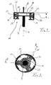
- Figure 1 shows schematically a body portion and an axle 1 with a mounted thereon Wheel 3, wherein the body portion 1 and the wheel axle 2 via a piston-cylinder damper 5 are connected.
- the damper 5 has a cylinder 7 and a damper rod 9 on. At the end of the damper rod 9, an inventive joint 11 is indicated.
- the hinge 11 has a first outer fitting 13, which is rotationally formed to form an axis is, which is coaxial with the longitudinal direction X of the damper rod 9.
- the main direction Z of the vibration load is parallel and coaxial with the longitudinal direction X.
- the outer fitting 13 extends in a body part (not shown) facing, closed portion 15 radially outward, and a portion 15 opposite, the piston-cylinder damper facing, open portion 17 is parallel formed to the closed portion 15, wherein the sections 15 and 17 with a to the sections perpendicular, axial connector form a Armaturiser.
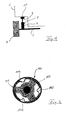
- the fitting comprises an inner receptacle 21, in which an elastomeric body 23 without use of vulcanization or adhesive is used mechanically.
- the elastomeric body 23 has a cross-sectionally T-shaped configuration, wherein two coupling arms 25 and 27 with the mutually sections 15 and 17 to form a Pressing force in contact.
- a perpendicular to the coupling arms 25, 27 and extending radially outward Pressure arm 31 is formed in contrast to the coupling arms 25, 27 only circular segments (see Fig. 2).
- the pressure arm 31 is pre-compressed in the receptacle 21 of the fitting 13 used that he a normal force in the direction perpendicular to the connecting piece 19th the armature 13 exerts, whereby an intermediate ring segment 33, which is a Reibdämpfungs adopted According to the invention, presses on the inner side surface of the armature 13.
- the intermediate ring segments 33 extend in the circumferential direction over the extent of Pressure arms 31 out to each other. In this way, a large friction surface between the intermediate ring segments 33 and the connecting piece 19 of the outer fitting 13 is provided become.
- a second armature 41 of the joint 11 is a rotation-shaped, disc-like armature 41st formed, which is fastened centrally to the free end of the damper rod 9.
- the peripheral edge the armature 41 is completely embedded in the elastomeric body 23.
- the joint according to the invention mainly has a vibration load in the direction of Z. This is via the damper rod 9 and the valve 41 in the elastomer body 23 initiated. At a vibration load of small amplitude is a static friction force between the friction surface of the intermediate ring segments 33 and the inner surface of the Connecting piece 19 of the outer fitting 13 so large that a slip of the intermediate ring segment 33 is prevented relative to the valve 13.
- FIG. 4 shows a further embodiment of a joint according to the invention, to which FIG the embodiment according to Figures 2 and 3 identical or similar components with the same Reference numerals are increased by 100.
- the embodiment according to FIG. 4 differs from that according to FIGS. 2 and 3 in that that the intermediate ring elements 133 are connected via flexible bridge pieces 143.
- the friction damping device consisting here of three intermediate ring elements 133 are made of one piece, which also the mountability of the Reibdämpfungs adopted simplified at the outer armature 113.
Priority Applications (2)
| Application Number | Priority Date | Filing Date | Title |
|---|---|---|---|
| DE50307574T DE50307574D1 (de) | 2003-11-04 | 2003-11-04 | Gelenk zum elastischen Koppeln zweier Bauteile und Dämpfer |
| EP03292757A EP1529982B1 (fr) | 2003-11-04 | 2003-11-04 | Articulation élastique pour la liaison entre deux pièces et amortisseur avec une telle articulation élastique |
Applications Claiming Priority (1)
| Application Number | Priority Date | Filing Date | Title |
|---|---|---|---|
| EP03292757A EP1529982B1 (fr) | 2003-11-04 | 2003-11-04 | Articulation élastique pour la liaison entre deux pièces et amortisseur avec une telle articulation élastique |
Publications (2)
| Publication Number | Publication Date |
|---|---|
| EP1529982A1 true EP1529982A1 (fr) | 2005-05-11 |
| EP1529982B1 EP1529982B1 (fr) | 2007-06-27 |
Family
ID=34429547
Family Applications (1)
| Application Number | Title | Priority Date | Filing Date |
|---|---|---|---|
| EP03292757A Expired - Fee Related EP1529982B1 (fr) | 2003-11-04 | 2003-11-04 | Articulation élastique pour la liaison entre deux pièces et amortisseur avec une telle articulation élastique |
Country Status (2)
| Country | Link |
|---|---|
| EP (1) | EP1529982B1 (fr) |
| DE (1) | DE50307574D1 (fr) |
Cited By (2)
| Publication number | Priority date | Publication date | Assignee | Title |
|---|---|---|---|---|
| WO2014108155A1 (fr) * | 2013-01-11 | 2014-07-17 | Audi Ag | Système amortisseur actif |
| CN111795925A (zh) * | 2019-04-05 | 2020-10-20 | 保时捷股份公司 | 在弹性结合的子系统中测定摩擦系数的方法和摩擦系数测定装置 |
Citations (11)
| Publication number | Priority date | Publication date | Assignee | Title |
|---|---|---|---|---|
| GB589383A (en) * | 1942-10-29 | 1947-06-19 | Lord Mfg Co | Resilient mountings |
| US2432050A (en) * | 1943-11-09 | 1947-12-02 | Gen Tire & Rubber Co | Energy dissipating antivibration device |
| FR1087744A (fr) * | 1953-11-23 | 1955-02-28 | Sncf | Amortisseur de choc à frottement sec |
| DE1074331B (de) * | 1956-08-27 | 1960-01-28 | W. H. Miner, Inc., Chicago, 111. (V. St. A.) | Reibungsstoßdämpfer |
| US3198506A (en) * | 1963-02-19 | 1965-08-03 | Lord Mfg Co | Mounting |
| US3232597A (en) * | 1962-09-13 | 1966-02-01 | Metalaslik Ltd | Dampers |
| FR2271454A1 (en) * | 1974-01-04 | 1975-12-12 | Kleber Colombes | Elastic shock absorber for wheel suspensions - with telescoping guide parts and elastic suspension sleeve of cellular elastomer |
| GB2041487A (en) * | 1979-02-09 | 1980-09-10 | Gomma Antivibranti Applic | Elastomeric mountings with friction damping of high amplitude movements |
| JPS62178410A (ja) * | 1986-01-31 | 1987-08-05 | Nissan Motor Co Ltd | ストラツトマウントインシユレ−タ |
| DE3624085A1 (de) * | 1986-07-17 | 1988-01-21 | Kloeckner Humboldt Deutz Ag | Stoss- und schwingungsdaempfendes lagerelement fuer die aufhaengung von antrieben |
| US20030015830A1 (en) * | 2001-07-20 | 2003-01-23 | Lord Corporation | Controlled equilibrium device with displacement dependent spring rates and integral damping |
-
2003
- 2003-11-04 DE DE50307574T patent/DE50307574D1/de not_active Expired - Lifetime
- 2003-11-04 EP EP03292757A patent/EP1529982B1/fr not_active Expired - Fee Related
Patent Citations (11)
| Publication number | Priority date | Publication date | Assignee | Title |
|---|---|---|---|---|
| GB589383A (en) * | 1942-10-29 | 1947-06-19 | Lord Mfg Co | Resilient mountings |
| US2432050A (en) * | 1943-11-09 | 1947-12-02 | Gen Tire & Rubber Co | Energy dissipating antivibration device |
| FR1087744A (fr) * | 1953-11-23 | 1955-02-28 | Sncf | Amortisseur de choc à frottement sec |
| DE1074331B (de) * | 1956-08-27 | 1960-01-28 | W. H. Miner, Inc., Chicago, 111. (V. St. A.) | Reibungsstoßdämpfer |
| US3232597A (en) * | 1962-09-13 | 1966-02-01 | Metalaslik Ltd | Dampers |
| US3198506A (en) * | 1963-02-19 | 1965-08-03 | Lord Mfg Co | Mounting |
| FR2271454A1 (en) * | 1974-01-04 | 1975-12-12 | Kleber Colombes | Elastic shock absorber for wheel suspensions - with telescoping guide parts and elastic suspension sleeve of cellular elastomer |
| GB2041487A (en) * | 1979-02-09 | 1980-09-10 | Gomma Antivibranti Applic | Elastomeric mountings with friction damping of high amplitude movements |
| JPS62178410A (ja) * | 1986-01-31 | 1987-08-05 | Nissan Motor Co Ltd | ストラツトマウントインシユレ−タ |
| DE3624085A1 (de) * | 1986-07-17 | 1988-01-21 | Kloeckner Humboldt Deutz Ag | Stoss- und schwingungsdaempfendes lagerelement fuer die aufhaengung von antrieben |
| US20030015830A1 (en) * | 2001-07-20 | 2003-01-23 | Lord Corporation | Controlled equilibrium device with displacement dependent spring rates and integral damping |
Non-Patent Citations (1)
| Title |
|---|
| PATENT ABSTRACTS OF JAPAN vol. 012, no. 018 (M - 660) 20 January 1988 (1988-01-20) * |
Cited By (5)
| Publication number | Priority date | Publication date | Assignee | Title |
|---|---|---|---|---|
| WO2014108155A1 (fr) * | 2013-01-11 | 2014-07-17 | Audi Ag | Système amortisseur actif |
| US9545831B2 (en) | 2013-01-11 | 2017-01-17 | Audi Ag | Active damper system |
| CN104918802B (zh) * | 2013-01-11 | 2017-07-21 | 奥迪股份公司 | 主动减振系统 |
| CN111795925A (zh) * | 2019-04-05 | 2020-10-20 | 保时捷股份公司 | 在弹性结合的子系统中测定摩擦系数的方法和摩擦系数测定装置 |
| CN111795925B (zh) * | 2019-04-05 | 2023-06-06 | 保时捷股份公司 | 在弹性结合的子系统中测定摩擦系数的方法和摩擦系数测定装置 |
Also Published As
| Publication number | Publication date |
|---|---|
| EP1529982B1 (fr) | 2007-06-27 |
| DE50307574D1 (de) | 2007-08-09 |
Similar Documents
| Publication | Publication Date | Title |
|---|---|---|
| DE102005046407B4 (de) | Motorabdeckung | |
| DE3831284C2 (de) | Strömungsmittelgefüllte elastische Buchse zum flexiblen Verbinden eines Schaftelements mit einem rohrförmigen Lagerelement | |
| DE7737712U1 (de) | Vorspannbares Lagerelement | |
| DE3028631A1 (de) | Axial belastbare huelsengummifeder | |
| DE102012107558A1 (de) | Struktur eines Aufhängungshalters für einen Hilfsrahmen | |
| DE102008009619A1 (de) | Abstimmbarer Massendämpfer für ein Mittenabstützlager einer Kardanwelle | |
| DE102017106289B4 (de) | Lagerbuchse | |
| DE102017108141B4 (de) | Achswellensystem mit zweistufiger steifigkeit und seite-zu-seite-steifigkeits-vorspannung | |
| WO2016162527A1 (fr) | Amortisseur d'oscillations pour chaîne cinématique | |
| WO2016091929A1 (fr) | Dispositif d'amortissement des vibrations | |
| DE202006008365U1 (de) | Wellenlager, insbesondere Gelenkwellenlager | |
| DE2933586C2 (de) | Schwingungstilger für rotierende Wellen | |
| DE102012019228A1 (de) | Zahnstangen-Lenkgetriebe mit Dämpfung an der Spurstangeneinheit | |
| DE4430393C5 (de) | Drehelastische Kupplung mit integriertem Torsionsschwingungsdämpfer | |
| EP1529982B1 (fr) | Articulation élastique pour la liaison entre deux pièces et amortisseur avec une telle articulation élastique | |
| DE19537462A1 (de) | Aggregatelager | |
| DE102017215768B4 (de) | Lager, vorzugsweise Motorlager oder Getriebelager | |
| EP0584821B1 (fr) | Accouplement élastique | |
| DE102013202690B4 (de) | Drehschwingungsdämpfer | |
| DE102014211051A1 (de) | Kraftfahrzeughinterachse | |
| DE4422579C2 (de) | Verbundbauteil als Zug-Druck-Stange für Schienenfahrzeuge | |
| DE102013005543A1 (de) | Achsführungslager zur Ankopplung einer Hinterachse an einen Fahrzeugaufbau eines Kraftfahrzeugs | |
| DE102012201227A1 (de) | Pendelstütze | |
| DE202008016135U1 (de) | Elastischer Gelenkkörper für eine Wellenanordnung | |
| DE102013010183A1 (de) | Bauteil für ein Schienenfahrzeugrad |
Legal Events
| Date | Code | Title | Description |
|---|---|---|---|
| PUAI | Public reference made under article 153(3) epc to a published international application that has entered the european phase |
Free format text: ORIGINAL CODE: 0009012 |
|
| AK | Designated contracting states |
Kind code of ref document: A1 Designated state(s): AT BE BG CH CY CZ DE DK EE ES FI FR GB GR HU IE IT LI LU MC NL PT RO SE SI SK TR |
|
| AX | Request for extension of the european patent |
Extension state: AL LT LV MK |
|
| 17P | Request for examination filed |
Effective date: 20050422 |
|
| AKX | Designation fees paid |
Designated state(s): DE FR |
|
| 17Q | First examination report despatched |
Effective date: 20050719 |
|
| GRAP | Despatch of communication of intention to grant a patent |
Free format text: ORIGINAL CODE: EPIDOSNIGR1 |
|
| GRAS | Grant fee paid |
Free format text: ORIGINAL CODE: EPIDOSNIGR3 |
|
| GRAA | (expected) grant |
Free format text: ORIGINAL CODE: 0009210 |
|
| AK | Designated contracting states |
Kind code of ref document: B1 Designated state(s): DE FR |
|
| REF | Corresponds to: |
Ref document number: 50307574 Country of ref document: DE Date of ref document: 20070809 Kind code of ref document: P |
|
| ET | Fr: translation filed | ||
| PLBE | No opposition filed within time limit |
Free format text: ORIGINAL CODE: 0009261 |
|
| STAA | Information on the status of an ep patent application or granted ep patent |
Free format text: STATUS: NO OPPOSITION FILED WITHIN TIME LIMIT |
|
| 26N | No opposition filed |
Effective date: 20080328 |
|
| REG | Reference to a national code |
Ref country code: FR Ref legal event code: PLFP Year of fee payment: 13 |
|
| REG | Reference to a national code |
Ref country code: DE Ref legal event code: R084 Ref document number: 50307574 Country of ref document: DE |
|
| REG | Reference to a national code |
Ref country code: FR Ref legal event code: PLFP Year of fee payment: 14 |
|
| REG | Reference to a national code |
Ref country code: FR Ref legal event code: PLFP Year of fee payment: 15 |
|
| PGFP | Annual fee paid to national office [announced via postgrant information from national office to epo] |
Ref country code: DE Payment date: 20201119 Year of fee payment: 18 Ref country code: FR Payment date: 20201120 Year of fee payment: 18 |
|
| REG | Reference to a national code |
Ref country code: DE Ref legal event code: R119 Ref document number: 50307574 Country of ref document: DE |
|
| PG25 | Lapsed in a contracting state [announced via postgrant information from national office to epo] |
Ref country code: DE Free format text: LAPSE BECAUSE OF NON-PAYMENT OF DUE FEES Effective date: 20220601 |
|
| PG25 | Lapsed in a contracting state [announced via postgrant information from national office to epo] |
Ref country code: FR Free format text: LAPSE BECAUSE OF NON-PAYMENT OF DUE FEES Effective date: 20211130 |