EP1529982A1 - Elastic mount between two units and shock absorber with such a mount - Google Patents
Elastic mount between two units and shock absorber with such a mount Download PDFInfo
- Publication number
- EP1529982A1 EP1529982A1 EP03292757A EP03292757A EP1529982A1 EP 1529982 A1 EP1529982 A1 EP 1529982A1 EP 03292757 A EP03292757 A EP 03292757A EP 03292757 A EP03292757 A EP 03292757A EP 1529982 A1 EP1529982 A1 EP 1529982A1
- Authority
- EP
- European Patent Office
- Prior art keywords
- joint according
- friction
- elastomeric body
- joint
- reibdämpfungseinrichtung
- Prior art date
- Legal status (The legal status is an assumption and is not a legal conclusion. Google has not performed a legal analysis and makes no representation as to the accuracy of the status listed.)
- Granted
Links
Images
Classifications
-
- B—PERFORMING OPERATIONS; TRANSPORTING
- B60—VEHICLES IN GENERAL
- B60G—VEHICLE SUSPENSION ARRANGEMENTS
- B60G13/00—Resilient suspensions characterised by arrangement, location or type of vibration dampers
- B60G13/001—Arrangements for attachment of dampers
- B60G13/003—Arrangements for attachment of dampers characterised by the mounting on the vehicle body or chassis of the damper unit
-
- F—MECHANICAL ENGINEERING; LIGHTING; HEATING; WEAPONS; BLASTING
- F16—ENGINEERING ELEMENTS AND UNITS; GENERAL MEASURES FOR PRODUCING AND MAINTAINING EFFECTIVE FUNCTIONING OF MACHINES OR INSTALLATIONS; THERMAL INSULATION IN GENERAL
- F16F—SPRINGS; SHOCK-ABSORBERS; MEANS FOR DAMPING VIBRATION
- F16F1/00—Springs
- F16F1/36—Springs made of rubber or other material having high internal friction, e.g. thermoplastic elastomers
- F16F1/38—Springs made of rubber or other material having high internal friction, e.g. thermoplastic elastomers with a sleeve of elastic material between a rigid outer sleeve and a rigid inner sleeve or pin, i.e. bushing-type
- F16F1/3863—Springs made of rubber or other material having high internal friction, e.g. thermoplastic elastomers with a sleeve of elastic material between a rigid outer sleeve and a rigid inner sleeve or pin, i.e. bushing-type characterised by the rigid sleeves or pin, e.g. of non-circular cross-section
-
- F—MECHANICAL ENGINEERING; LIGHTING; HEATING; WEAPONS; BLASTING
- F16—ENGINEERING ELEMENTS AND UNITS; GENERAL MEASURES FOR PRODUCING AND MAINTAINING EFFECTIVE FUNCTIONING OF MACHINES OR INSTALLATIONS; THERMAL INSULATION IN GENERAL
- F16F—SPRINGS; SHOCK-ABSORBERS; MEANS FOR DAMPING VIBRATION
- F16F1/00—Springs
- F16F1/36—Springs made of rubber or other material having high internal friction, e.g. thermoplastic elastomers
- F16F1/38—Springs made of rubber or other material having high internal friction, e.g. thermoplastic elastomers with a sleeve of elastic material between a rigid outer sleeve and a rigid inner sleeve or pin, i.e. bushing-type
- F16F1/387—Springs made of rubber or other material having high internal friction, e.g. thermoplastic elastomers with a sleeve of elastic material between a rigid outer sleeve and a rigid inner sleeve or pin, i.e. bushing-type comprising means for modifying the rigidity in particular directions
-
- F—MECHANICAL ENGINEERING; LIGHTING; HEATING; WEAPONS; BLASTING
- F16—ENGINEERING ELEMENTS AND UNITS; GENERAL MEASURES FOR PRODUCING AND MAINTAINING EFFECTIVE FUNCTIONING OF MACHINES OR INSTALLATIONS; THERMAL INSULATION IN GENERAL
- F16F—SPRINGS; SHOCK-ABSORBERS; MEANS FOR DAMPING VIBRATION
- F16F9/00—Springs, vibration-dampers, shock-absorbers, or similarly-constructed movement-dampers using a fluid or the equivalent as damping medium
- F16F9/32—Details
- F16F9/54—Arrangements for attachment
Definitions
- the invention relates to an elastic joint for elastically coupling two components and a damper.
- the elastic joint should be under load high frequency and low amplitude (typically 250 Hz, 0.01 mm) low Rigidity values and a weak damping to provide an acoustic insulation to reach the components to be connected elastically, ie the transmission of noise, for example, by rolling the tire on a road at high speed be caused to limit.
- high frequency and low amplitude typically 250 Hz, 0.01 mm
- a weak damping to provide an acoustic insulation to reach the components to be connected elastically, ie the transmission of noise, for example, by rolling the tire on a road at high speed be caused to limit.
- low frequencies with high amplitudes typically 10 Hz and 0.5 mm
- a high degree of damping is required, so when driving over, for example, road surveys safe driving characteristics are ensured for the motor vehicle.
- viscoelastic materials but with increasing frequency a solidification of the material goes along.
- an elastic joint and a damper with an elastic To create a joint that, while maintaining low manufacturing costs vibration loads in the entire spectrum of large and small amplitudes and frequencies one has good durability, the elastic joint an acoustic decoupling guaranteed even at low frequencies and high amplitude.
- a friction damping device with the elastomer body is connected, which is formed of a material which is more rigid than that of the elastomeric body is.
- the joint according to the invention has a softer material, which causes an acoustic coupling, especially in the high frequency range, and a stiffer Material that is responsible for the sliding and static friction in the joint and wear-resistant is ensured and a low-noise friction sliding.
- the elastomeric body and the Reibdämpfungsenutter at least partially from a Be made piece of material, wherein the Reibdämpfungs observed forming part by solidifying agent is stiffened to the desired level.
- the friction damping device has at least one friction surface on, at which the elastomeric body with one of the components directly or indirectly is coupled such that at a load of small amplitude a static friction and at a Gleitreibschlupf is formed of a large amplitude load.
- the friction surface directly with a mating surface area of the component or with the elastomeric body too interconnecting joint fitting cooperate according to the invention.
- the friction damping device is structurally independent, formed of the elastomeric body separate intermediate member, which on a the region of the elastomeric body assigned to the component to be connected is firmly attached.
- the intermediate component can be cupped or layered to reduce space requirements be formed, that is, with a dimension by one over the length and depth low strength is determined.
- the friction surface of the Reibdämpfungs is provided in the respective operating conditions the Haftreibschluß or Gleitreibschlupf permits.
- the friction damping device can be used on many various locations in the joint to form at least one, preferably two or a plurality of friction surfaces, preferably four friction surfaces, be provided.
- the friction surface of the friction damping device is such designed so that when exceeding an amplitude threshold, a function transition from the Haftreibschluß in Gleitreibschlupf takes place at the friction surface pre-determinable.
- This predeterminable setting of an amplitude threshold may be due to the particular choice the friction coefficient at the friction surface and / or by the friction surface through the Elastomer body acting normal force can be realized.
- the friction surface is particularly effective, i. especially then a lot of stress energy destroyed by friction losses, if they are substantially parallel to the main direction of the Vibration load is aligned.
- this angle is at least less than 45 °, i. the predominant directional component the area corresponds to the main direction of the vibration load.
- the elastomer body is for the application of a normal force responsible in the direction of the friction surface of the Reibdämpfungs founded to the corresponding To generate static friction or sliding friction.
- This normal force preferably caused by precompression of the elastomeric body.
- the precompression is preferably only when mounting the joint either directly to the used Components or to intermediate parts, such as hinged joints realized.
- the elastomeric body of the joint with two coupling arms which are substantially opposite to each other and substantially aligned parallel to the main direction of the vibration load, and with a with provided the Reibdämpfungs worn cooperating pressure arm.
- the pressure arm is on the one hand responsible for applying the normal force to the friction surface, on the other for receiving transversely to the main direction acting forces on the joint.
- the two Coupling arms are there to be connected for a basic damping between the elastic Components to ensure and the transition from Haftreibschluß- to GleitreibschlupfMap to shape continuously.
- the elastomeric body is in the assembled state in the area of all three arms, namely coupling arms and pressure arm, precompressed.
- the elastomeric body is rotationally shaped and has a T-shaped cross section, wherein the pressure arm forms the main leg, while the Side legs are realized by the coupling arms.
- a stop is provided which especially in a Gleitreibschlupf the Gleitreibterrorism the damping device the friction surface preferably limited in the main loading direction.
- the Movement limits by the stop according to a specific dimensioning of Reibdämpfungs leverage be set.
- the joint has a valve on, which has a Jacobreib Structure which is attributable to the friction surface.
- the counter friction surface and the friction surface abut each other and ensure at a vibration load small amplitude a safe Haftreibschluß for transmitting the vibrational forces from the fitting into the elastomer body or vice versa and at a vibration load large amplitude a Gleitreibschlupf.
- Gleitreibschlupf so there is a Relative movement between the valve and the friction surface of the Reibdämpfungs adopted forming section.
- the counter friction surface can also provide adjustable parameters, such as coefficient of friction can be used to determine the amplitude threshold at which a Haftreibschluß in the Gleitreibschlupf passes.
- the fitting is provided with a receptacle for the elastomeric body.
- the elastomeric body is completely mechanical attached to the fitting, i. without a vulcanization process or adhesive too use.
- a plurality of damping devices at least two Reibdämpfungs wornen provided, the flexibly connected together are.
- a manufacturing technology particularly simple and cost-effective solution for the Reibdämpfungs is realized when all Reibdämpfungs wornen and this connecting bridge pieces in one piece, in particular a plastic piece, preferably a piece of polyamide.
- the elastomeric body is pre-compressed to apply the normal force to the friction surface is the Reibdämpfungs adopted additionally reinforced.
- the friction damping device as an intermediate component is realized, and made of a rigid plastic, such as polyamide is, for solidification of the rigid plastic enrichment by glass fibers be provided.
- a 30% glass fiber content very good Gleitreibeigenschaften and static friction properties offering a long life.
- a particularly advantageous embodiment of the invention relates to a joint with two fittings, one of which is a fitting on one of the components and the other fitting on the other Component is attached.
- the two fittings connects the elastomeric body, at least a friction damping device is provided between a fitting and the elastomeric body is.
- the second fitting vulcanized in the elastomeric body or on the elastomeric body. at a preferred embodiment surrounds a rotary-shaped fitting, which is a receptacle for forms the elastomer body, the second valve.
- the invention relates to a damper for motor vehicles with an inventive Joint attached to the end of a shock absorber rod of a chassis damper and designed for mounting on a motor vehicle body.
- a particularly simple one Assembly can be realized with a joint that has a fitting for attachment to the Damper rod and a fitting for attachment to a motor vehicle body part has.
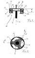
- Figure 1 shows schematically a body portion and an axle 1 with a mounted thereon Wheel 3, wherein the body portion 1 and the wheel axle 2 via a piston-cylinder damper 5 are connected.
- the damper 5 has a cylinder 7 and a damper rod 9 on. At the end of the damper rod 9, an inventive joint 11 is indicated.
- the hinge 11 has a first outer fitting 13, which is rotationally formed to form an axis is, which is coaxial with the longitudinal direction X of the damper rod 9.
- the main direction Z of the vibration load is parallel and coaxial with the longitudinal direction X.
- the outer fitting 13 extends in a body part (not shown) facing, closed portion 15 radially outward, and a portion 15 opposite, the piston-cylinder damper facing, open portion 17 is parallel formed to the closed portion 15, wherein the sections 15 and 17 with a to the sections perpendicular, axial connector form a Armaturiser.
- the fitting comprises an inner receptacle 21, in which an elastomeric body 23 without use of vulcanization or adhesive is used mechanically.
- the elastomeric body 23 has a cross-sectionally T-shaped configuration, wherein two coupling arms 25 and 27 with the mutually sections 15 and 17 to form a Pressing force in contact.
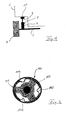
- a perpendicular to the coupling arms 25, 27 and extending radially outward Pressure arm 31 is formed in contrast to the coupling arms 25, 27 only circular segments (see Fig. 2).
- the pressure arm 31 is pre-compressed in the receptacle 21 of the fitting 13 used that he a normal force in the direction perpendicular to the connecting piece 19th the armature 13 exerts, whereby an intermediate ring segment 33, which is a Reibdämpfungs adopted According to the invention, presses on the inner side surface of the armature 13.
- the intermediate ring segments 33 extend in the circumferential direction over the extent of Pressure arms 31 out to each other. In this way, a large friction surface between the intermediate ring segments 33 and the connecting piece 19 of the outer fitting 13 is provided become.
- a second armature 41 of the joint 11 is a rotation-shaped, disc-like armature 41st formed, which is fastened centrally to the free end of the damper rod 9.
- the peripheral edge the armature 41 is completely embedded in the elastomeric body 23.
- the joint according to the invention mainly has a vibration load in the direction of Z. This is via the damper rod 9 and the valve 41 in the elastomer body 23 initiated. At a vibration load of small amplitude is a static friction force between the friction surface of the intermediate ring segments 33 and the inner surface of the Connecting piece 19 of the outer fitting 13 so large that a slip of the intermediate ring segment 33 is prevented relative to the valve 13.
- FIG. 4 shows a further embodiment of a joint according to the invention, to which FIG the embodiment according to Figures 2 and 3 identical or similar components with the same Reference numerals are increased by 100.
- the embodiment according to FIG. 4 differs from that according to FIGS. 2 and 3 in that that the intermediate ring elements 133 are connected via flexible bridge pieces 143.
- the friction damping device consisting here of three intermediate ring elements 133 are made of one piece, which also the mountability of the Reibdämpfungs adopted simplified at the outer armature 113.
Abstract
Description
Die Erfindung betrifft ein elastisches Gelenk zum elastischen Koppeln zweier Bauteile und einen Dämpfer.The invention relates to an elastic joint for elastically coupling two components and a damper.
Um einen Kolben-Zylinder-Dämpfer an ein Fahrzeugchassis anzubringen, ist bekannt, das Ende einer Stange des Kolbens des Dämpfers über ein elastisches Gelenk an ein Fahrzeugkarosseriebauteil zu befestigen. Derartige elastische Gelenke haben die allgemeine Funktion, unter Gewährleistung einer gewissen Steifheit auch gute Dämpfungseigenschaften bereitzustellen.To attach a piston-cylinder damper to a vehicle chassis, it is known End of a rod of the piston of the damper via an elastic joint to a vehicle body component to fix. Such elastic joints have the general function, while providing a certain stiffness and good damping properties.
Für eine anzustrebende Funktionsweise soll einerseits das elastische Gelenk bei einer Belastung mit hoher Frequenz und geringer Amplitude (üblicherweise 250 Hz, 0,01 mm) geringe Steifigkeitswerte und eine schwache Dämpfung erbringen, um damit eine akustische Isolierung der elastisch zu verbindenden Bauteilen zu erreichen, also um die Übertragung von Geräuschen, die beispielsweise durch das Rollen des Reifens auf einer Straße bei hoher Geschwindigkeit hervorgerufen werden, zu begrenzen. Andererseits sind bei kleinen Frequenzen mit großen Amplituden (üblicherweise 10 Hz und 0,5 mm) ein hohes Dämpfungsmaß erforderlich, damit beim Überfahren beispielsweise von Straßenerhebungen sichere Fahreigenschaften für das Kraftfahrzeug sichergestellt sind. Üblicherweise werden für elastische Gelenke viskoelastische Materialien herangezogen, bei denen allerdings mit Zunahme der Frequenz eine Verfestigung des Materials einhergeht.For a desired mode of functioning, on the one hand, the elastic joint should be under load high frequency and low amplitude (typically 250 Hz, 0.01 mm) low Rigidity values and a weak damping to provide an acoustic insulation to reach the components to be connected elastically, ie the transmission of noise, for example, by rolling the tire on a road at high speed be caused to limit. On the other hand, at low frequencies with high amplitudes (typically 10 Hz and 0.5 mm) a high degree of damping is required, so when driving over, for example, road surveys safe driving characteristics are ensured for the motor vehicle. Usually, for elastic joints viscoelastic materials, but with increasing frequency a solidification of the material goes along.
Ferner ist bekannt, einen Elastomerkörper zwischen zwei Armaturen eines Gelenks anzuordnen, wobei im Falle von großen Amplituden ein Reibschlupf zwischen der Armatur und dem Elastomerkörper realisiert wird. Aufgrund der dabei auftretenden Gleitreibung wird ein erheblicher Teil der in das elastische Gelenk eingeleiteten Energie vernichtet, nämlich in Wärme- und Reibarbeit umgewandelt, wodurch die oben genannten gewünschten Gelenkeigenschaften schon sehr zufriedenstellend realisierbar sind. Insbesondere werden sehr gute Dämpfungswerte bei einer Belastung hoher Amplitude erzielt. Furthermore, it is known to arrange an elastomeric body between two armatures of a joint, in the case of large amplitudes, a slip between the valve and the Elastomer body is realized. Due to the occurring sliding friction is a significant Part of the energy introduced into the elastic joint, namely heat and friction work, resulting in the above-mentioned desired joint properties already very satisfactorily realizable. In particular, very good attenuation values achieved at a high amplitude load.
Ein derartiges elastisches Gelenk ist allerdings insofern nachteilig, als das Gleiten des Elastomerkörpers entlang der Armatur starke störende Geräusche hervorrufen kann, die unmittelbar in die Fahrgastzelle übertragen werden. Diese Geräusche treten vor allem bei bestimmten Temperatur- und Luftfeuchtigkeitsverhältnissen verstärkt auf, weswegen es schwierig ist, diese Geräusche genau zu bestimmen und diese unter allen vorstellbaren Umständen unterbindende Gegenmaßnahmen zu treffen.However, such an elastic joint is disadvantageous insofar as the sliding of the elastomer body along the valve can cause strong disturbing noises, the immediate be transferred to the passenger compartment. These sounds occur especially at certain Temperature and humidity conditions, which is why it is difficult to pinpoint these noises and suppress them under all imaginable circumstances To take countermeasures.
Ferner leidet das bekannte elastische Gelenk mit Gleitreibschlupfbereich daran, daß sich der Elastomerkörper mit zunehmender Zeit aufgrund des Gleitreibung abnutzt und dadurch seine Dämpfungseigenschaft wegen des Kontaktverlusts mit dem zugeordneten Bauteil gänzlich verliert. Als Gegenmaßnahme gegen zu schnelle Abnutzung ist bekannt, statt natürlichem Elastomer ein Polyurethan-Material zu verwenden, das allerdings wegen dessen hohen Materialkosten für ein Massenprodukt, wie ein elastisches Gelenk an einem Kraftfahrzeugdämpfer, äußerst unwirtschaftlich ist.Furthermore, the known elastic joint with Gleitreibschlupfbereich suffers from the fact that the Elastomer body wears with increasing time due to the sliding friction and thereby its Damping property due to the loss of contact with the associated component entirely loses. As a countermeasure against too rapid wear is known, instead of natural Elastomer to use a polyurethane material, however, because of its high material costs for a mass product, such as an elastic joint on a vehicle damper, is extremely uneconomical.
Es ist Aufgabe der Erfindung, ein elastisches Gelenk und einen Dämpfer mit einem elastischen Gelenk zu schaffen, das unter Wahrung geringer Herstellungskosten Schwingungsbelastungen im gesamten Spektrum von großen und kleinen Amplituden und Frequenzen eine gute Dauerbeständigkeit aufweist, wobei das elastische Gelenk eine akustische Entkopplung auch bei niedrigen Frequenzen und hoher Amplitude gewährleistet.It is an object of the invention, an elastic joint and a damper with an elastic To create a joint that, while maintaining low manufacturing costs vibration loads in the entire spectrum of large and small amplitudes and frequencies one has good durability, the elastic joint an acoustic decoupling guaranteed even at low frequencies and high amplitude.
Diese Aufgabe wird dadurch gelöst, daß mit dem Elastomerkörper eine Reibdämpfungseinrichtung verbunden ist, welche aus einem Material gebildet ist, das starrer als das des Elastomerkörpers ist. Auf diese Weise weist das erfindungsgemäße Gelenk ein weicheres Material, das eine akustische Kopplung vor allem im Hochfrequenzbereich bewirkt, und ein steiferes Material auf, das für die Gleit- und Haftreibung im Gelenk zuständig ist und verschleißbeständig ist sowie ein geräuscharmes Reibgleiten gewährleistet. Dabei können erfindungsgemäß der Elastomerkörper und die Reibdämpfungsenrichtung zumindest teilweise aus einem Materialstück gefertigt sein, wobei der die Reibdämpfungseinrichtung bildende Teil durch verfestigende Mittel auf das gewünschte Maß versteift ist. Hierfür kann zum Beispiel ein Glasfasermaterial oder andere, den Elastomer verfestigende Werkstoffe herangezogen werden. Zudem weist erfindungsgemäß die Reibdämpfungseinrichtung wenigstens eine Reibfläche auf, an welcher der Elastomerkörper mit einem der Bauteile unmittelbar oder mittelbar derart gekoppelt ist, daß bei einer Belastung kleiner Amplitude ein Haftreibschluß und bei einer Belastung großer Amplitude ein Gleitreibschlupf gebildet ist. Dabei kann die Reibfläche direkt mit einem Gegenflächenbereich des Bauteils oder einer mit dem Elastomerkörper zu verbindenden Gelenkarmatur erfindungsgemäß zusammenwirken.This object is achieved in that a friction damping device with the elastomer body is connected, which is formed of a material which is more rigid than that of the elastomeric body is. In this way, the joint according to the invention has a softer material, which causes an acoustic coupling, especially in the high frequency range, and a stiffer Material that is responsible for the sliding and static friction in the joint and wear-resistant is ensured and a low-noise friction sliding. It can according to the invention the elastomeric body and the Reibdämpfungsenrichtung at least partially from a Be made piece of material, wherein the Reibdämpfungseinrichtung forming part by solidifying agent is stiffened to the desired level. For this example, a Fiberglass or other, the elastomer solidifying materials are used. In addition, according to the invention, the friction damping device has at least one friction surface on, at which the elastomeric body with one of the components directly or indirectly is coupled such that at a load of small amplitude a static friction and at a Gleitreibschlupf is formed of a large amplitude load. In this case, the friction surface directly with a mating surface area of the component or with the elastomeric body too interconnecting joint fitting cooperate according to the invention.
Bei einer bevorzugten Ausführung ist die Reibdämpfungseinrichtung als strukturell eigenständiges, von dem Elastomerkörper separates Zwischenbauteil ausgebildet, das an einem dem zu verbindenden Bauteil zugeordneten Bereich des Elastomerkörpers fest angebracht ist. Das Zwischenbauteil kann zur Reduzierung von Raumbedarf schalenartig oder lagenartig ausgebildet sein, also mit einer Abmessung, die durch eine gegenüber der Länge und Tiefe geringe Stärke bestimmt ist. An der von dem Elastomerkörper abgwandten, freien Seitenfläche des Zwischenbauteils ist die Reibfläche der Reibdämpfungseinrichtung vorgesehen, die in den jeweiligen Betriebszuständen den Haftreibschluß oder den Gleitreibschlupf zuläßt.In a preferred embodiment, the friction damping device is structurally independent, formed of the elastomeric body separate intermediate member, which on a the region of the elastomeric body assigned to the component to be connected is firmly attached. The intermediate component can be cupped or layered to reduce space requirements be formed, that is, with a dimension by one over the length and depth low strength is determined. At the abgwandten of the elastomeric body, free side surface the intermediate component, the friction surface of the Reibdämpfungseinrichtung is provided in the respective operating conditions the Haftreibschluß or Gleitreibschlupf permits.
Bei der separaten Ausbildung der Reibdämpfungseinrichtung als Zwischenbauteil hat es sich als besonders vorteilhaft herausgestellt, daß ein elastomerfreies Material verwendet werden kann. Überraschenderweise werden sehr gute, einstellbare Haftreibungs- und Gleitreibungseigenschaften durch starre Kunststoffmaterialien, wie Polyamide, erzielt. Als besonders geeignet stellte sich ein mit Glasfaser verstärktes Polyamid heraus.In the separate embodiment of the Reibdämpfungseinrichtung as an intermediate component, it has found to be particularly advantageous that an elastomer-free material can be used can. Surprisingly, very good, adjustable static friction and sliding friction properties achieved by rigid plastic materials, such as polyamides. As especially suitable turned out a glass fiber reinforced polyamide.
Ein weiterer Vorteil der strukturell separierten Ausbildung der Reibdämpfungseinrichtung besteht darin, daß die Herstellungskosten für das elastische Gelenk gegenüber den bekannten elastischen Gelenken mit Haftreibschluß und Gleitreibschlupf reduziert werden können. Als mit den bekannten Gelenken mit Polyurethan-Materialien für den Elastomerkörper eine teure Lösung für ein einigermaßen dauerbeständiges Gelenk vorgeschlagen wird, kann mit dem erfindungsgemäßen Gelenk ein natürlicher Elastomer für den Elastomerkörper, beispielsweise Kautschuk, verwendet werden, über das eine Menge Erfahrungswerte hinsichtlich der Fertigung von elastischen Gelenken existiert.Another advantage of the structurally separated design of Reibdämpfungseinrichtung is that the cost of manufacturing the elastic joint over the known elastic joints with Haftreibschluß and Gleitreibschlupf can be reduced. When with the known joints with polyurethane materials for the elastomeric body an expensive Solution for a reasonably durable joint can be proposed with the joint according to the invention a natural elastomer for the elastomeric body, for example Rubber, used, has a lot of experience in terms of manufacturing of elastic joints exists.
Je nach Belastungsart und Belastungsrichtung kann die Reibdämpfungseinrichtung an vielen verschiedenen Stellen im Gelenk unter Ausbildung von mindestens einer, vorzugsweise zwei oder mehreren Reibflächen, bevorzugterweise vier Reibflächen, vorgesehen sein.Depending on the type of load and the direction of loading, the friction damping device can be used on many various locations in the joint to form at least one, preferably two or a plurality of friction surfaces, preferably four friction surfaces, be provided.
Bei einer Weiterbildung der Erfindung ist die Reibfläche der Reibdämpfungseinrichtung derart ausgelegt, daß bei einer Überschreitung einer Amplitudenschwelle ein Funktionsübergang von dem Haftreibschluß in den Gleitreibschlupf an der Reibfläche vorbestimmbar stattfindet. Diese vorbestimmbare Einstellung einer Amplitudenschwelle kann durch die besondere Wahl des Reibungskoeffizienten an der Reibfläche und/oder durch die an der Reibfläche durch den Elastomerkörper wirkende Normalkraft verwirklicht werden. Hierbei erweist sich erneut die separate Ausbildung von Elastomerkörper und Reibdämpfungseinrichtung als Vorteil, als ein großes Spektrum an Reibflächen je nach Wahl des Materials für die Reibdämpfungseinrichtung zur Verfügung steht.In a further development of the invention, the friction surface of the friction damping device is such designed so that when exceeding an amplitude threshold, a function transition from the Haftreibschluß in Gleitreibschlupf takes place at the friction surface pre-determinable. This predeterminable setting of an amplitude threshold may be due to the particular choice the friction coefficient at the friction surface and / or by the friction surface through the Elastomer body acting normal force can be realized. This proves again the separate training of elastomeric body and Reibdämpfungseinrichtung as an advantage, as a wide range of friction surfaces depending on the choice of material for the Reibdämpfungseinrichtung is available.
Die Reibfläche ist besonders dann wirksam, d.h. kann besonders dann viel Belastungsenergie durch Reibungsverluste vernichten, wenn sie im wesentlichen parallel zur Hauptrichtung der Schwingungsbelastung ausgerichtet ist. Selbstverständlich kann die Reibfläche auch in einem Winkel zur Hauptrichtung der Schwingungsbelastung liegen, allerdings ist bevorzugt, daß dieser Winkel wenigstens kleiner als 45° ist, d.h. die überwiegenden Richtungskomponente der Fläche entspricht der Hauptrichtung der Schwingungsbelastung.The friction surface is particularly effective, i. especially then a lot of stress energy destroyed by friction losses, if they are substantially parallel to the main direction of the Vibration load is aligned. Of course, the friction surface in a Angle to the main direction of the vibration load, however, it is preferred that this angle is at least less than 45 °, i. the predominant directional component the area corresponds to the main direction of the vibration load.
Wie oben bereits angedeutet ist, ist der Elastomerkörper für das Aufbringen einer Normalkraft in Richtung auf die Reibfläche der Reibdämpfungseinrichtung verantwortlich, um die entsprechende Haftreibungs- bzw. Gleitreibungskraft zu erzeugen. Diese Normalkraft, wird vorzugsweise durch Vorkomprimierung des Elastomerkörpers hervorgerufen. Die Vorkomprimierung wird vorzugsweise erst bei Montage des Gelenks entweder direkt an die zu verwendenden Bauteile oder an Zwischenteile, wie Gelenkarmaturen, realisiert.As already indicated above, the elastomer body is for the application of a normal force responsible in the direction of the friction surface of the Reibdämpfungseinrichtung to the corresponding To generate static friction or sliding friction. This normal force, preferably caused by precompression of the elastomeric body. The precompression is preferably only when mounting the joint either directly to the used Components or to intermediate parts, such as hinged joints realized.
Bei einer bevorzugten Ausführung der Erfindung ist der Elastomerkörper des Gelenks mit zwei Kopplungsarmen, die im wesentlichen entgegengesetzt zueinander und im wesentlichen parallel zur Hauptrichtung der Schwingungsbelastung ausgerichtet sind, und mit einem mit der Reibdämpfungseinrichtung zusammenwirkenden Druckarm versehen. Der Druckarm ist zum einen zum Aufbringen der Normalkraft an der Reibfläche verantwortlich, zum anderen zum Aufnehmen von quer zur Hauptrichtung angreifenden Kräften an dem Gelenk. Die zwei Kopplungsarme sind dazu da, für eine Grunddämpfung zwischen den elastische zu verbindenden Bauteilen zu sorgen und den Übergang vom Haftreibschluß- zum Gleitreibschlupfzustand kontinuierlich zu gestalten. Vorzugsweise ist der Elastomerkörper im montierten Zustand im Bereich aller drei Arme, nämlich Kopplungsarme und Druckarm, vorkomprimiert. In a preferred embodiment of the invention, the elastomeric body of the joint with two coupling arms which are substantially opposite to each other and substantially aligned parallel to the main direction of the vibration load, and with a with provided the Reibdämpfungseinrichtung cooperating pressure arm. The pressure arm is on the one hand responsible for applying the normal force to the friction surface, on the other for receiving transversely to the main direction acting forces on the joint. The two Coupling arms are there to be connected for a basic damping between the elastic Components to ensure and the transition from Haftreibschluß- to Gleitreibschlupfzustand to shape continuously. Preferably, the elastomeric body is in the assembled state in the area of all three arms, namely coupling arms and pressure arm, precompressed.
Bei einer Weiterbildung der Erfindung ist der Elastomerkörper rotationsförmig und weist einen T-förmigen Querschnitt auf, wobei der Druckarm den Hauptschenkel bildet, während die Seitenschenkel durch die Kopplungsarme realisiert sind.In a further development of the invention, the elastomeric body is rotationally shaped and has a T-shaped cross section, wherein the pressure arm forms the main leg, while the Side legs are realized by the coupling arms.
Bei einer erfindungsgemäßen Weiterbildung des Gelenks ist ein Anschlag vorgesehen, der insbesondere bei einem Gleitreibschlupf die Gleitreibbewegung der Dämpfungseinrichtung an der Reibfläche vorzugsweise in Hauptbelastungsrichtung begrenzt. Beispielsweise können die Bewegungsgrenzen durch den Anschlag entsprechend einer bestimmten Dimensionierung der Reibdämpfungseinrichtung festgelegt werden.In a further development of the joint according to the invention, a stop is provided which especially in a Gleitreibschlupf the Gleitreibbewegung the damping device the friction surface preferably limited in the main loading direction. For example, the Movement limits by the stop according to a specific dimensioning of Reibdämpfungseinrichtung be set.
Bei einer besonders bevorzugten Weiterbildung der Erfindung weist das Gelenk eine Armatur auf, die eine Gegenreibfläche aufweist, welche der Reibfläche zuzuordnen ist. Die Gegenreibfläche und die Reibfläche liegen aneinander und gewährleisten bei einer Schwingungsbelastung kleiner Amplitude einen sicheren Haftreibschluß zur Übertragung der Schwingungskräfte von der Armatur in den Elastomerkörper oder umgekehrt und bei einer Schwingungsbelastung großer Amplitude einen Gleitreibschlupf. Beim Gleitreibschlupf besteht also eine Relativbewegung zwischen der Armatur und dem die Reibfläche der Reibdämpfungseinrichtung bildenden Abschnitt.In a particularly preferred embodiment of the invention, the joint has a valve on, which has a Gegenreibfläche which is attributable to the friction surface. The counter friction surface and the friction surface abut each other and ensure at a vibration load small amplitude a safe Haftreibschluß for transmitting the vibrational forces from the fitting into the elastomer body or vice versa and at a vibration load large amplitude a Gleitreibschlupf. When Gleitreibschlupf so there is a Relative movement between the valve and the friction surface of the Reibdämpfungseinrichtung forming section.
Auch die Gegenreibfläche kann einstellbare Parameter, wie Reibungskoeffizient, bieten, die zur Bestimmung der Amplitudenschwelle nutzbar sind, bei der ein Haftreibschluß in den Gleitreibschlupf übergeht.The counter friction surface can also provide adjustable parameters, such as coefficient of friction can be used to determine the amplitude threshold at which a Haftreibschluß in the Gleitreibschlupf passes.
Um die Gleitreibschlupfbewegung insbesondere in Hauptdämpfungsrichtung zu begrenzen, ist die Armatur mit einer Aufnahme für den Elastomerkörper versehen. Durch die besondere Dimensionierung der Aufnahme sowie der Reibdämpfungseinrichtung können großzügige bzw. enge Freiräume realisiert werden, die je nach Gelenkausführung eine große Bewegungsfreiheit bzw. eine reduzierte Bewegungsfreiheit für den Gleitreibschlupf bereitstellen.In order to limit the sliding friction slip movement, in particular in the main damping direction, the fitting is provided with a receptacle for the elastomeric body. By the special Dimensioning of the recording and the Reibdämpfungseinrichtung can generous or tight spaces are realized, depending on the joint design a large freedom of movement or provide a reduced freedom of movement for Gleitreibschlupf.
Bei einer bevorzugten Ausführung der Erfindung ist der Elastomerkörper vollständig mechanisch an der Armatur angebracht, d.h. ohne ein Vulkanisationsverfahren oder Haftmittel zu verwenden. In a preferred embodiment of the invention, the elastomeric body is completely mechanical attached to the fitting, i. without a vulcanization process or adhesive too use.
Bei einer besonderen Weiterbildung der Erfindung sind mehrere Dämpfungseinrichtungen, mindestens zwei Reibdämpfungseinrichtungen, vorgesehen, die miteinander flexibel verbunden sind. Mit dieser flexiblen Verbindung ist die Montage der separat ausgebildeten Reibdämpfungseinrichtung in einer Armatur wesentlich vereinfacht, denn die Reibdämpfungseinrichtung, an sich ein separates Bauteil, kann einfach zur Montage bezüglich der Armaturen und/oder des Elastomerkörpers positioniert werden.In a particular embodiment of the invention, a plurality of damping devices, at least two Reibdämpfungseinrichtungen provided, the flexibly connected together are. With this flexible connection, the assembly of the separately formed Reibdämpfungseinrichtung considerably simplified in a fitting, because the Reibdämpfungseinrichtung, in itself a separate component, can be easy to mount with respect to the fittings and / or the elastomeric body are positioned.
Eine fertigungstechnisch besonders einfache und kostengünstige Lösung für die Reibdämpfungseinrichtung wird realisiert, wenn sämtliche Reibdämpfungseinrichtungen sowie die diese verbindenden Brückenstücke aus einem Stück, insbesondere einem Kunststoffstück, vorzugsweise einem Polyamidstück, verbunden sind.A manufacturing technology particularly simple and cost-effective solution for the Reibdämpfungseinrichtung is realized when all Reibdämpfungseinrichtungen and this connecting bridge pieces in one piece, in particular a plastic piece, preferably a piece of polyamide.
Bei der bevorzugten Ausführung der Erfindung, bei der insbesondere der Elastomerkörper zum Aufbringen der Normalkraft an der Reibfläche vorkomprimiert ist, ist die Reibdämpfungseinrichtung zusätzlich verstärkt. Im Falle daß die Reibdämpfungseinrichtung als Zwischenbauteil realisiert ist, und aus einem starren Kunststoff, beispielsweise Polyamid, hergestellt ist, kann zur Verfestigung des starren Kunststoffs eine Anreicherung durch Glasfasern vorgesehen werden. Als besonders geeignet stellte sich hierbei überraschenderweise heraus, daß ein 30%iger Glasfaseranteil sehr gute Gleitreibeigenschaften sowie Haftreibeigenschaften bei Gewähren einer langen Lebensdauer bietet.In the preferred embodiment of the invention, in particular the elastomeric body is pre-compressed to apply the normal force to the friction surface is the Reibdämpfungseinrichtung additionally reinforced. In the case that the friction damping device as an intermediate component is realized, and made of a rigid plastic, such as polyamide is, for solidification of the rigid plastic enrichment by glass fibers be provided. Surprisingly, it turned out to be particularly suitable that a 30% glass fiber content very good Gleitreibeigenschaften and static friction properties offering a long life.
Eine besonders vorteilhafte Ausführung der Erfindung betrifft ein Gelenk mit zwei Armaturen, von denen eine Armatur an einem der Bauteile und die andere Armatur an dem anderen Bauteil befestigt ist. Die beiden Armaturen verbindet der Elastomerkörper, wobei zumindest zwischen einer Armatur und dem Elastomerkörper eine Reibdämpfungseinrichtung vorgesehen ist.A particularly advantageous embodiment of the invention relates to a joint with two fittings, one of which is a fitting on one of the components and the other fitting on the other Component is attached. The two fittings connects the elastomeric body, at least a friction damping device is provided between a fitting and the elastomeric body is.
Ist eine oder mehrere Reibdämpfungseinrichtungem nur an einem Bauteil, so ist vorzugsweise die zweite Armatur in dem Elastomerkörper oder an dem Elastomerkörper anvulkanisiert. Bei einer bevorzugten Ausführung umgibt eine rotationsförmige Armatur, die eine Aufnahme für den Elastomerkörper bildet, die zweite Armatur.If one or more Reibdämpfungseinrichtungemem only on a component, it is preferred the second fitting vulcanized in the elastomeric body or on the elastomeric body. at a preferred embodiment surrounds a rotary-shaped fitting, which is a receptacle for forms the elastomer body, the second valve.
Des weiteren betrifft die Erfindung einen Dämpfer für Kraftfahrzeuge mit einem erfindungsgemäßen Gelenk, das am Ende einer Dämpferstange eines Fahrwerksdämpfers befestigt ist und zum Montieren an einer Kraftfahrzeugkarosserie ausgelegt ist. Eine besonders einfache Montage kann mit einem Gelenk realisiert werden, das eine Armatur zum Anbringen an die Dämpferstange und eine Armatur zum Anbringen an ein Kraftfahrzeugkarosserieteil aufweist.Furthermore, the invention relates to a damper for motor vehicles with an inventive Joint attached to the end of a shock absorber rod of a chassis damper and designed for mounting on a motor vehicle body. A particularly simple one Assembly can be realized with a joint that has a fitting for attachment to the Damper rod and a fitting for attachment to a motor vehicle body part has.
Weitere Eigenschaften, Vorteile und Merkmale der Erfindung werden durch die nun folgende Beschreibung bevorzugter Ausführungen der Erfindung anhand der beiliegenden Zeichnungen deutlich, in denen zeigen:
- Fig. 1
- eine schematische Ansicht eines Fahrwerksabschnitts eines Kraftfahrzeugs mit einem erfindungsgemäßen Dämpfer;
- Fig. 2
- eine Querschnittsansicht eines erfindungsgemäßen Gelenks, gesehen in Hauptrichtung der Schwingungsbelastung;
- Fig. 3
- eine Querschnittsansicht des erfindungsgemäßen Gelenks entlang der Schnittlinie III-III gemäß Fig. 2; und
- Fig. 4
- eine Querschnittsansicht einer weiteren Ausführung eines erfindungsgemäßen Gelenks, gesehen in der Hauptrichtung der Schwingungsbelastung.
- Fig. 1
- a schematic view of a chassis section of a motor vehicle with a damper according to the invention;
- Fig. 2
- a cross-sectional view of a joint according to the invention, seen in the main direction of the vibration load;
- Fig. 3
- a cross-sectional view of the joint according to the invention along the section line III-III of FIG. 2; and
- Fig. 4
- a cross-sectional view of another embodiment of a joint according to the invention, seen in the main direction of the vibration load.
Figur 1 zeigt schematisch einen Karosserieabschnitt und eine Achse 1 mit einem daran montierten
Rad 3, wobei der Karosserieabschnitt 1 und die Radachse 2 über einen Kolben-Zylinder-Dämpfer
5 verbunden sind. Der Dämpfer 5 weist einen Zylinder 7 und eine Dämpferstange
9 auf. Am Ende der Dämpferstange 9 ist ein erfindungsgemäßes Gelenk 11 angedeutet.Figure 1 shows schematically a body portion and an axle 1 with a
In den Figuren 2 und 3 ist eine Ausführung des erfindungsgemäßen Gelenks näher dargestellt.
Das Gelenk 11 weist eine erste Außenarmatur 13 auf, die rotationsförmig zu einer Achse ausgebildet
ist, die koaxial zur Längsrichtung X der Dämpferstange 9 liegt.In Figures 2 and 3, an embodiment of the joint according to the invention is shown in more detail.
The
Die Hauptrichtung Z der Schwingungsbelastung liegt parallel und koaxial zur Längsrichtung X. The main direction Z of the vibration load is parallel and coaxial with the longitudinal direction X.
Die Außenarmatur 13 erstreckt sich in einem dem Karosserieteil (nicht dargestellt) zugewandten,
geschlossenen Abschnitt 15 radial nach außen, und ein dem Abschnitt 15 gegenüberliegender,
dem Kolben-Zylinder-Dämpfer zugewandter, offener Abschnitt 17 ist parallel
zum geschlossenen Abschnitt 15 ausgebildet, wobei die Abschnitte 15 und 17 mit einem zu
den Abschnitten senkrechten, axialen Verbindungsstück eine Armatureinheit bilden.The
Die Armatur umfaßt eine Innenaufnahme 21, in der ein Elastomerkörper 23 ohne Verwendung
von Vulkanisations- oder Haftmittel mechanisch eingesetzt ist.The fitting comprises an inner receptacle 21, in which an
Der Elastomerkörper 23 weist eine im Querschnitt T-förmige Gestalt auf, wobei zwei Kopplungsarme
25 bzw. 27 mit den zueinander Abschnitten 15 bzw. 17 unter Ausbildung einer
Andrückkraft in Kontakt sind.The
Ein sich zu den Kopplungsarmen 25, 27 senkrecht und radial nach außen erstreckender
Druckarm 31 ist im Gegensatz zu den Kopplungsarmen 25, 27 nur kreissegmentmäßig ausgebildet
(siehe Fig. 2). Der Druckarm 31 ist derart vorkomprimiert in der Aufnahme 21 der Armatur
13 eingesetzt, daß er eine Normalkraft in Richtung senkrecht zum Verbindungsstück 19
der Armatur 13 ausübt, wodurch ein Zwischenringsegment 33, das eine Reibdämpfungseinrichtung
gemäß der Erfindung darstellt, an die Innenseitenfläche der Armatur 13 drückt.A perpendicular to the
Bei der Ausführung des erfindungsgemäßen Gelenks gemäß Figur 2 und 3 sind jeweils drei
Zwischenringsegmente 33 vorgesehen, die nicht miteinander verbunden sind.In the embodiment of the joint according to the invention according to Figures 2 and 3 are each three
Die Zwischenringsegmente 33 erstrecken sich in Umfangsrichtung über die Ausdehnung der
Druckarme 31 hinaus aufeinander zu. Auf diese Weise kann eine große Reibfläche zwischen
den Zwischenringsegmenten 33 und dem Verbindungsstück 19 der Außenarmatur 13 bereitgestellt
werden.The
Eine zweite Armatur 41 des Gelenks 11 ist als rotationsförmige, scheibenartige Armatur 41
ausgebildet, die mittig an dem freien Ende der Dämpferstange 9 befestigt ist. Der Umfangsrand
der Armatur 41 ist vollständig in dem Elastomerkörper 23 eingebettet.A second armature 41 of the joint 11 is a rotation-shaped, disc-like armature 41st
formed, which is fastened centrally to the free end of the
Im Betrieb wirkt auf das erfindungsgemäße Gelenk hauptsächlich eine Schwingungsbelastung
in Richtung Z. Diese wird über die Dämpferstange 9 und der Armatur 41 in den Elastomerkörper
23 eingeleitet. Bei einer Schwingungsbelastung kleiner Amplitude ist eine Haftreibungskraft
zwischen der Reibfläche der Zwischenringsegmente 33 und der Innenfläche des
Verbindungsstücks 19 der Außenarmatur 13 derart groß, daß ein Schlupf des Zwischenringsegments
33 relativ zur Armatur 13 verhindert wird.In operation, the joint according to the invention mainly has a vibration load
in the direction of Z. This is via the
Bei einer Schwingungsbelastung großer Amplitude wird die an der Reibfläche angreifende
Belastungskraft derart groß, daß die Haftreibungskraft überwunden wird, und es zu einem
Schlupf an den Reibflächen der Zwischenringsegmente und der Innenfläche des Abschnitts 19
der Armatur 13 kommt. Auf diese Weise ist gewährleistet, daß das erfindungsgemäße Gelenk
eine hohe Dämpfungseigenschaft aufweist, wobei ein großer Teil der in das Gelenk eingebrachten
Belastungsarbeit durch die Gleitreibungsschlupfarbeit vernichtet wird.In a vibration load of high amplitude, the attacking on the friction surface
Loading force so large that the static friction force is overcome, and it to a
Slip on the friction surfaces of the intermediate ring segments and the inner surface of the portion 19th
the
In Figur 4 ist eine weitere erfindungsgemäße Ausführung eines Gelenks dargestellt, wobei zu der Ausführung gemäß den Figuren 2 und 3 identische oder ähnliche Bauteile mit denselben Bezugsziffern versehen sind, die um 100 erhöht sind.FIG. 4 shows a further embodiment of a joint according to the invention, to which FIG the embodiment according to Figures 2 and 3 identical or similar components with the same Reference numerals are increased by 100.
Die Ausführung gemäß Figur 4 unterscheidet sich von der gemäß den Figuren 2 und 3 darin,
daß die Zwischenringelemente 133 über flexible Brückenstücke 143 verbunden sind. Auf diese
Weise kann die Reibdämpfungseinrichtung bestehend hier aus drei Zwischenringelementen
133 aus einem Stück gefertigt werden, was zudem die Montierbarkeit der Reibdämpfungseinrichtung
an der äußeren Armatur 113 vereinfacht.The embodiment according to FIG. 4 differs from that according to FIGS. 2 and 3 in that
that the
Die in der vorstehenden Beschreibung, den Figuren und den Ansprüchen offenbarten Merkmale können sowohl einzeln als auch in beliebiger Kombination für die Realisierung der Erfindung in den verschiedenen Ausgestaltungen von Bedeutung sein. The features disclosed in the foregoing description, figures and claims can both individually and in any combination for the realization of the invention be important in the various embodiments.
- 11
- Karosserieabschnittbody section
- 22
- Achseaxis
- 33
- Radwheel
- 55
- Kolben-Zylinder-DämpferPiston-damper
- 77
- Zylindercylinder
- 99
- Dämpferstangedamper rod
- 1111
- Gelenkjoint
- 1313
- Außenarmaturoutside tap
- 1515
- geschlossener Abschnittclosed section
- 1717
- offener Abschnittopen section
- 1919
- Verbindungsstückjoint
- 2121
- InnenaufnahmeIndoors
- 2323
- Elastomerkörperelastomer body
- 25,2725.27
- Kopplungsarmecoupling arms
- 3131
- Druckarmpressure arm
- 3333
- ZwischenringsegmenteBetween ring segments
- 4141
- Armaturfitting
- 133133
- ZwischenringsegmenteBetween ring segments
- 143143
- flexible Brückenstückeflexible bridge pieces
- XX
- Längsrichtunglongitudinal direction
- ZZ
- HauptbelastungsrichtungMain load direction
Claims (17)
Priority Applications (2)
| Application Number | Priority Date | Filing Date | Title |
|---|---|---|---|
| EP03292757A EP1529982B1 (en) | 2003-11-04 | 2003-11-04 | Elastic mount between two units and shock absorber with such a mount |
| DE50307574T DE50307574D1 (en) | 2003-11-04 | 2003-11-04 | Joint for elastically coupling two components and dampers |
Applications Claiming Priority (1)
| Application Number | Priority Date | Filing Date | Title |
|---|---|---|---|
| EP03292757A EP1529982B1 (en) | 2003-11-04 | 2003-11-04 | Elastic mount between two units and shock absorber with such a mount |
Publications (2)
| Publication Number | Publication Date |
|---|---|
| EP1529982A1 true EP1529982A1 (en) | 2005-05-11 |
| EP1529982B1 EP1529982B1 (en) | 2007-06-27 |
Family
ID=34429547
Family Applications (1)
| Application Number | Title | Priority Date | Filing Date |
|---|---|---|---|
| EP03292757A Expired - Fee Related EP1529982B1 (en) | 2003-11-04 | 2003-11-04 | Elastic mount between two units and shock absorber with such a mount |
Country Status (2)
| Country | Link |
|---|---|
| EP (1) | EP1529982B1 (en) |
| DE (1) | DE50307574D1 (en) |
Cited By (2)
| Publication number | Priority date | Publication date | Assignee | Title |
|---|---|---|---|---|
| WO2014108155A1 (en) * | 2013-01-11 | 2014-07-17 | Audi Ag | Active damper system |
| CN111795925A (en) * | 2019-04-05 | 2020-10-20 | 保时捷股份公司 | Method for determining the coefficient of friction in an elastically integrated sub-system and device for determining the coefficient of friction |
Citations (11)
| Publication number | Priority date | Publication date | Assignee | Title |
|---|---|---|---|---|
| GB589383A (en) * | 1942-10-29 | 1947-06-19 | Lord Mfg Co | Resilient mountings |
| US2432050A (en) * | 1943-11-09 | 1947-12-02 | Gen Tire & Rubber Co | Energy dissipating antivibration device |
| FR1087744A (en) * | 1953-11-23 | 1955-02-28 | Sncf | Dry friction shock absorber |
| DE1074331B (en) * | 1956-08-27 | 1960-01-28 | W. H. Miner, Inc., Chicago, 111. (V. St. A.) | Friction shock absorbers |
| US3198506A (en) * | 1963-02-19 | 1965-08-03 | Lord Mfg Co | Mounting |
| US3232597A (en) * | 1962-09-13 | 1966-02-01 | Metalaslik Ltd | Dampers |
| FR2271454A1 (en) * | 1974-01-04 | 1975-12-12 | Kleber Colombes | Elastic shock absorber for wheel suspensions - with telescoping guide parts and elastic suspension sleeve of cellular elastomer |
| GB2041487A (en) * | 1979-02-09 | 1980-09-10 | Gomma Antivibranti Applic | Elastomeric mountings with friction damping of high amplitude movements |
| JPS62178410A (en) * | 1986-01-31 | 1987-08-05 | Nissan Motor Co Ltd | Strut mount insulator |
| DE3624085A1 (en) * | 1986-07-17 | 1988-01-21 | Kloeckner Humboldt Deutz Ag | Shock- and vibration-damping support element for the suspension mount of drives |
| US20030015830A1 (en) * | 2001-07-20 | 2003-01-23 | Lord Corporation | Controlled equilibrium device with displacement dependent spring rates and integral damping |
-
2003
- 2003-11-04 DE DE50307574T patent/DE50307574D1/en not_active Expired - Lifetime
- 2003-11-04 EP EP03292757A patent/EP1529982B1/en not_active Expired - Fee Related
Patent Citations (11)
| Publication number | Priority date | Publication date | Assignee | Title |
|---|---|---|---|---|
| GB589383A (en) * | 1942-10-29 | 1947-06-19 | Lord Mfg Co | Resilient mountings |
| US2432050A (en) * | 1943-11-09 | 1947-12-02 | Gen Tire & Rubber Co | Energy dissipating antivibration device |
| FR1087744A (en) * | 1953-11-23 | 1955-02-28 | Sncf | Dry friction shock absorber |
| DE1074331B (en) * | 1956-08-27 | 1960-01-28 | W. H. Miner, Inc., Chicago, 111. (V. St. A.) | Friction shock absorbers |
| US3232597A (en) * | 1962-09-13 | 1966-02-01 | Metalaslik Ltd | Dampers |
| US3198506A (en) * | 1963-02-19 | 1965-08-03 | Lord Mfg Co | Mounting |
| FR2271454A1 (en) * | 1974-01-04 | 1975-12-12 | Kleber Colombes | Elastic shock absorber for wheel suspensions - with telescoping guide parts and elastic suspension sleeve of cellular elastomer |
| GB2041487A (en) * | 1979-02-09 | 1980-09-10 | Gomma Antivibranti Applic | Elastomeric mountings with friction damping of high amplitude movements |
| JPS62178410A (en) * | 1986-01-31 | 1987-08-05 | Nissan Motor Co Ltd | Strut mount insulator |
| DE3624085A1 (en) * | 1986-07-17 | 1988-01-21 | Kloeckner Humboldt Deutz Ag | Shock- and vibration-damping support element for the suspension mount of drives |
| US20030015830A1 (en) * | 2001-07-20 | 2003-01-23 | Lord Corporation | Controlled equilibrium device with displacement dependent spring rates and integral damping |
Non-Patent Citations (1)
| Title |
|---|
| PATENT ABSTRACTS OF JAPAN vol. 012, no. 018 (M - 660) 20 January 1988 (1988-01-20) * |
Cited By (5)
| Publication number | Priority date | Publication date | Assignee | Title |
|---|---|---|---|---|
| WO2014108155A1 (en) * | 2013-01-11 | 2014-07-17 | Audi Ag | Active damper system |
| US9545831B2 (en) | 2013-01-11 | 2017-01-17 | Audi Ag | Active damper system |
| CN104918802B (en) * | 2013-01-11 | 2017-07-21 | 奥迪股份公司 | Active vibration-reducing system |
| CN111795925A (en) * | 2019-04-05 | 2020-10-20 | 保时捷股份公司 | Method for determining the coefficient of friction in an elastically integrated sub-system and device for determining the coefficient of friction |
| CN111795925B (en) * | 2019-04-05 | 2023-06-06 | 保时捷股份公司 | Method for determining friction coefficient in elastic combination subsystem and friction coefficient determining device |
Also Published As
| Publication number | Publication date |
|---|---|
| EP1529982B1 (en) | 2007-06-27 |
| DE50307574D1 (en) | 2007-08-09 |
Similar Documents
| Publication | Publication Date | Title |
|---|---|---|
| DE102005046407B4 (en) | engine cover | |
| DE3831284C2 (en) | Fluid-filled elastic bushing for flexibly connecting a shaft element to a tubular bearing element | |
| DE7737712U1 (en) | Prestressable bearing element | |
| DE3028631A1 (en) | AXIAL LOADABLE SLEEVE RUBBER SPRING | |
| DE102012107558A1 (en) | Structure of a suspension bracket for a subframe | |
| DE102008009619A1 (en) | Tunable mass damper for a center support bearing of a cardan shaft | |
| DE102017108141B4 (en) | AXLE WHEEL STIFFNESS AND PAGE-TO-SIDE STIFFNESS PRELOAD | |
| WO2018171963A1 (en) | Bearing bush | |
| WO2016162527A1 (en) | Vibration damper for a drive train | |
| WO2016091929A1 (en) | Device for damping vibrations | |
| DE202006008365U1 (en) | Bearing support for articulated automotive drive shaft has foam plastic support sleeve | |
| DE2933586C2 (en) | Vibration absorber for rotating shafts | |
| DE102012019228A1 (en) | Rack and pinion steering with damping on the tie rod unit | |
| DE4430393C5 (en) | Torsionally flexible coupling with integrated torsional vibration damper | |
| EP1529982B1 (en) | Elastic mount between two units and shock absorber with such a mount | |
| DE19537462A1 (en) | Aggregate bearing comprising step bearing | |
| DE102012201227A1 (en) | Hinged support for supporting e.g. gear box, in car, has elastomeric body mounted inside receiving opening of bearing housing, where rib is provided in receiving opening for engaging undercut of elastomeric body | |
| DE102017215768B4 (en) | Bearings, preferably engine bearings or gear bearings | |
| EP0584821B1 (en) | Flexible coupling | |
| DE102013202690B4 (en) | Torsional vibration damper | |
| DE102014211051A1 (en) | Motor vehicle rear axle | |
| DE102013005543A1 (en) | Achsführungslager for coupling a rear axle to a vehicle body of a motor vehicle | |
| DE10018744C2 (en) | Torsionally flexible coupling for pulleys | |
| DE202008016135U1 (en) | Elastic joint body for a shaft arrangement | |
| DE102013010183A1 (en) | Component for a rail vehicle wheel |
Legal Events
| Date | Code | Title | Description |
|---|---|---|---|
| PUAI | Public reference made under article 153(3) epc to a published international application that has entered the european phase |
Free format text: ORIGINAL CODE: 0009012 |
|
| AK | Designated contracting states |
Kind code of ref document: A1 Designated state(s): AT BE BG CH CY CZ DE DK EE ES FI FR GB GR HU IE IT LI LU MC NL PT RO SE SI SK TR |
|
| AX | Request for extension of the european patent |
Extension state: AL LT LV MK |
|
| 17P | Request for examination filed |
Effective date: 20050422 |
|
| AKX | Designation fees paid |
Designated state(s): DE FR |
|
| 17Q | First examination report despatched |
Effective date: 20050719 |
|
| GRAP | Despatch of communication of intention to grant a patent |
Free format text: ORIGINAL CODE: EPIDOSNIGR1 |
|
| GRAS | Grant fee paid |
Free format text: ORIGINAL CODE: EPIDOSNIGR3 |
|
| GRAA | (expected) grant |
Free format text: ORIGINAL CODE: 0009210 |
|
| AK | Designated contracting states |
Kind code of ref document: B1 Designated state(s): DE FR |
|
| REF | Corresponds to: |
Ref document number: 50307574 Country of ref document: DE Date of ref document: 20070809 Kind code of ref document: P |
|
| ET | Fr: translation filed | ||
| PLBE | No opposition filed within time limit |
Free format text: ORIGINAL CODE: 0009261 |
|
| STAA | Information on the status of an ep patent application or granted ep patent |
Free format text: STATUS: NO OPPOSITION FILED WITHIN TIME LIMIT |
|
| 26N | No opposition filed |
Effective date: 20080328 |
|
| REG | Reference to a national code |
Ref country code: FR Ref legal event code: PLFP Year of fee payment: 13 |
|
| REG | Reference to a national code |
Ref country code: DE Ref legal event code: R084 Ref document number: 50307574 Country of ref document: DE |
|
| REG | Reference to a national code |
Ref country code: FR Ref legal event code: PLFP Year of fee payment: 14 |
|
| REG | Reference to a national code |
Ref country code: FR Ref legal event code: PLFP Year of fee payment: 15 |
|
| PGFP | Annual fee paid to national office [announced via postgrant information from national office to epo] |
Ref country code: DE Payment date: 20201119 Year of fee payment: 18 Ref country code: FR Payment date: 20201120 Year of fee payment: 18 |
|
| REG | Reference to a national code |
Ref country code: DE Ref legal event code: R119 Ref document number: 50307574 Country of ref document: DE |
|
| PG25 | Lapsed in a contracting state [announced via postgrant information from national office to epo] |
Ref country code: DE Free format text: LAPSE BECAUSE OF NON-PAYMENT OF DUE FEES Effective date: 20220601 |
|
| PG25 | Lapsed in a contracting state [announced via postgrant information from national office to epo] |
Ref country code: FR Free format text: LAPSE BECAUSE OF NON-PAYMENT OF DUE FEES Effective date: 20211130 |