EP1529713B1 - Lenkapparat - Google Patents
Lenkapparat Download PDFInfo
- Publication number
- EP1529713B1 EP1529713B1 EP04026218A EP04026218A EP1529713B1 EP 1529713 B1 EP1529713 B1 EP 1529713B1 EP 04026218 A EP04026218 A EP 04026218A EP 04026218 A EP04026218 A EP 04026218A EP 1529713 B1 EP1529713 B1 EP 1529713B1
- Authority
- EP
- European Patent Office
- Prior art keywords
- outer jacket
- slit
- bracket segments
- inner column
- notch
- Prior art date
- Legal status (The legal status is an assumption and is not a legal conclusion. Google has not performed a legal analysis and makes no representation as to the accuracy of the status listed.)
- Expired - Fee Related
Links
Images


Classifications
-
- B—PERFORMING OPERATIONS; TRANSPORTING
- B62—LAND VEHICLES FOR TRAVELLING OTHERWISE THAN ON RAILS
- B62D—MOTOR VEHICLES; TRAILERS
- B62D1/00—Steering controls, i.e. means for initiating a change of direction of the vehicle
- B62D1/02—Steering controls, i.e. means for initiating a change of direction of the vehicle vehicle-mounted
- B62D1/16—Steering columns
- B62D1/18—Steering columns yieldable or adjustable, e.g. tiltable
- B62D1/184—Mechanisms for locking columns at selected positions
Definitions
- This invention relates to a steering apparatus, and particularly to a tilt-telescopic steering apparatus capable of adjusting the tilting angle of a steering wheel and the position thereof in an axial direction according to the driving posture of a driver.
- Apreviously known steering apparatus for a motor vehicle is a tilt-telescopic steering capable of the tilting angle of a steering wheel according to the physique and driving attitude of a driver and the axial position of the steering wheel.
- JP-T-10-512826 discloses a steering apparatus in which the yoke supporting the steering shaft arranged in an outer column tube is shifted along a vertical groove formed at a pair of bracket segments, thereby adjusting the tilting angle of the steering shaft.
- An other example is the UA-A-6 139 057.
- the yoke is provided between the outer column tube and the steering shaft, in order to realize the telescopic adjustment in this structure, it is necessary to provide an inner column tube having a long hole in an axial direction outside the yoke in the radial direction, separately from the outer column tube.
- the provision of the inner column tube outside the yoke presents a problem of large-scaling of the device.
- a certain gap allowing relative sliding during the adjustment must be provided between the inner column tube and the yoke. If the gap is large, a back-lash may be generated.
- the gap is small, the sliding resistance increases. This presents a problem that dimension adjustment of the gap must be strictly carried out.
- a gap for relative sliding must be provided also between the inner column tube and the outer column tube. This gives rise to the same problem and also increases the labor and time of machining.
- the inventors of this invention have developed a steering apparatus in which an outer jacket incorporating an inner column movably in a direction of the axial line and being at least partially cylindrical is provided and using the friction force acted between its diameter-reduced portion and the inner column is used to fix the inner column.
- a slit is preferably formed on the outer periphery thereof.
- the provision of the slit gives rise to stress concentration on the outer jacket.
- increasing the rigidity of the outer jacket by e.g. increasing the sectional thickness of the outer jacket can be proposed. This, however, presents a new problem that increases in size and weight of the steering apparatus occur and a large operating force is required during tilting.
- this invention has been accomplished, and intends to provide a steering apparatus having an outer jacket with optimi zed balance of rigidity.
- the invention provides a steering apparatus including: an inner column which rotatably supports a steering shaft; an outer jacket which incorporates the inner column shiftably in an axial direction, at least a portion of the outer jacket being cylindrical; and an urging member for urging the inner column; wherein the outer jacket includes: a pressed portion which extends in a direction leaving an axial line from the outer periphery of the outer jacket and is urged by the urging member, a slit which extends in the axial direction over the pressed portion from the end of the outer jacket, and a notch which leads to the slit extending over the pressed portion; and the notch has a tapered shape which enlarges toward an opening side when the outer jacket is viewed in an urging direction of the urging member.
- the invention provides a steering apparatus, including: an inner column which rotatably supports a steering shaft; an outer jacket which incorporates the inner column shiftably in an axial direction, at least a portion of the outer jacket being cylindrical; and an urging member for urging the inner column; wherein the outer jacket includes: a pressed portion which extends in a direction leaving an axial line from the outer periphery of the outer jacket and is urged by the urging member, a slit which extends in the axial direction over the pressed portion from the end of the outer jacket, a notch which leads to the slit extending over the pressed portion, and a rib extending in the axial direction on the outer periphery opposite to the slit with respect to the axial line.
- the invention provides a steering apparatus for supporting a steering shaft attached to a steering wheel shiftably in an axial direction, including: an inner column which rotatably supports the steering shaft; a pair of bracket segments attached to a vehicle body and arranged at opposite positions with respect to an axial line of the steering shaft; a tension member extended between the pair of bracket segments; two fixing members for fixing the tension member from outside of the pair of bracket segments; a displacement applying member arranged between the tension member and the fixing members for applying a relative displacement between the bracket segments and the fixing members in interlock with a movement of an operating lever; and a cylindrical outer jacket held to the vehicle body by coupling the tension member, the bracket segments and the fixing member and having a flange with an outer periphery to be in contact with the bracket segments by the relative displacement of the bracket segments at least between the pair of bracket segments, and an inner periphery wrapping the outer periphery of the inner column; wherein the pair of bracket segments approach each other by the relative displacement given by the applying member so that a pressing force is given to the
- the invention provides a steering apparatus for supporting a steering shaft attached to a steering wheel shiftably in an axial direction, comprising: an inner column which rotatably supports the steering shaft; a pair of bracket segments attached to a vehicle body and arranged at opposite positions with respect to an axial line of the steering shaft; a tension member extended between the pair of bracket segments; two fixing members for fixing the tension member from outside of the pair of bracket segments; a displacement applying member arranged between the tension member and the firing members for applying a relative displacement between the bracket segments and the fixing members in interlock with a movement of an operating lever; and a cylindrical outer jacket held to the vehicle body by coupling the tensionmember, the bracket segments and the fixing member and having a flange with an outer periphery to be in contact with the bracket segments by the relative displacement of the bracket segments at least between the pair of bracket segments, and an inner periphery wrapping the outer periphery of the inner column; the pair of bracket segments approach each other by the relative displacement given by the applying member so that a pressing force is given to the inner
- the notch is formed within a range of ⁇ 90° from the center of the slit.
- Fig. 1 is a side view of a tilt-telescopic steering apparatus 10 according to an embodiment of this invention.
- Fig. 2 is a bottom view of the steering apparatus 10 shown in Fig. 1.
- Fig. 3 is a perspective view of the steering apparatus shown in Fig. 1 in its exploded state (a coil spring 30 is not shown) .
- Fig. 4 is a view taken in line IV-IV in Fig. 1 when viewed in an arrow direction.
- an attached bracket 12 has a structure in which bracket segments 12a, 12a extending in parallel in a vertical direction are coupled by a coupling plate 12d, the bracket segments having a pair of body attaching holes 12c (formed in a pair of body attaching planes 12e, respectively) which are employed to attach the bracket 12 to a vehicle body B (Fig. 4) by bolts 28 (Fig. 4).
- the attached bracket 12 is made by bending a single plate material.
- the respective bracket segments 12a, 12a has equal plate thicknesses and shapes which are line-symmetrical with respect to a vertical line passing a steering axial line.
- a tension member 13 is arranged between the bracket segments 12a and 12a.
- the tension member 13 is attached to sandwich the outer periphery at the end of the outer j jacket 21. Namely, the tension member 13 can be divided into the body 13a and the tube 13b, so that it is excellent in the assembling property when loaded in the vehicle.
- the tension member 13 has a ring shape which is circumferentially continuous and hence provides high rigidity.
- the bolt 14 may be a standard product.
- the tube 13b can be made by only cutting a cylindrical tube in a predetermined length. Thus, the tension member 13 can be made at a lower cost.
- the tube 13b may be also made by welding a rolled plate material.
- the outer jacket 21 includes a cylinder 21a and a pair of first plate-like flange 21c (near to the end) and second plate-like flanges 21d (far from the end) which are arranged axially apart to sandwich the tension member 13 on the outer periphery at the end of the cylinder 21a.
- the outer jacket 21 has an ear 21h formed at the upper position of the left end of the cylinder 21a in Fig. 1.
- the ear 21h has a through-hole 21i. Using a bolt (not shown) passed through the through-hole 21i and fixed to the vehicle body, the outer jacket 21 is swingably attached to the vehicle body 21.
- the cylinder 21a has a notch 21f having a triangular shape when viewed in direction indicated in Fig. 1 on the lower surface of the outer jacket 21 at a more forward position of the vehicle than the flanges 21c and 21d.
- the cylinder 21a internally holds (incorporates) the inner column 11 on the lower surface of the outer jacket 21.
- the cylinder 21a is pivotally supported to the vehicle body (not shown) (vertically in Fig. 1) around a pivoting point O which accords with the axial line of the through-hole 21i. Between the flanges 21c and 21d functioning as the pressed portion, the tension member 13 is arranged.
- the cylinder 21a has an upper flat surface 21s between the flanges 21c and 21d so that the tension member 13a is stably mounted on the cylinder 21a.
- a slit 21e is formed to extend axially across at least the flanges 21c and 21d from the end of the cylinder 21a.
- the line connecting the centers of the fixing members 16 and 17 may cross the axial of the inner column 11.
- a steering shaft S is internally passed through the cylindrical inner column 11 sheathed by the outer jacket 21, and rotatably supported by the inner column 11 by a bearing 29 (Fig. 1) .
- the inner column 11 may have a long hole serving as a telescopic stopper formed in parallel to the axis of the steering shaft S and engaged with a bolt implanted in the outer jacket.
- this structure is not indispensable.
- Each bracket segment 12a has a tilting groove 12b which serves as a part of the arc around a pivoting point O.
- the tilting groove 12b is located at the position displaced backward of the vehicle in an axial line of the inner column from a body attaching hole 12c of the bracket 12 which is the body attaching portion arranged at a height near the axial line of the steering shaft S (see Figs. 1 and 2).
- a fixing member 16 is passed through the tilting groove 12b.
- a fixing member 17 is passed through the tilting groove 12b.
- the end of the bracket segment 12a on the side of the tilting groove 12b with respect to the body attaching hole 12c may be bent.
- the fixing bolt 16 which is a headed bolt includes a disk-shaped head 16a which is larger than the width of the tilting groove 12b on the left side in Fig. 4 and has a tool engaging hole, a cylindrical tilt-guiding segment 16b which is guided in engagement in the tilting groove 12b, and a male screw 16c which is firmly screw-engaged in a screw hole 13c formed in the body 13a of the tension member 13.
- the fixing member 17 includes a hexagonal head 17a to which a tool is to be engaged, a first screw segment 17b, a cylindrical shaft 17c, a small flange 17d and a second screw segment 17e.
- the second screw segment 17e is firmly screw-engaged in the screw hole 13d formed in the body 13a of the tension member 13 so that the small flange 17d is in contact with the surface 13a of the body 13.
- a fixed cam 18 which consists of a tilt-guiding segment 18a having an elliptical section engaged to the width of the tilting groove 12b and fixed cam segment 18b having a larger diameter than the width
- a movable cam 19 having a cam face to be engaged to the fixed cam segment 18b
- an operating lever 20 which rotates integrally to the fixed cam 19
- a thrust bearing which may be a rolling or a sliding bearing 22.
- the fixed cam 18, movable cam 19, bracket segments 12a, 12a function as an urging member.
- the fixed cam 18 and the movable cam 19 function as a displacement applying member.
- the fixing member 17, nut 23 and fixing member 16 function as a fixing member.
- a coil spring 30 is arranged to surround the inner column 11 and to be secured, at its ends 30a, to the respective bracket segments 12a.
- the coil spring 30 has a pair of coil segments 30b on its both sides and a central contact segment 30c which is in contact with the lower surface of the inner column 11 exposed from the notch 21f of the outer jacket 21.
- the lower surface of the inner column 11 is, therefore, always urgedupward by the urging force of the coil spring 30.
- a projection 21k is provided at the lowermost position of the notch 21f to prevent the coil spring 30 from coming off.
- Fig. 5 is a side view of the flange side of the outer jacket 21 viewed from side (urging direction of the urging member).
- Fig. 6 is a bottom view of the flange side of the outer jacket 21 viewed from bottom.
- Fig. 7 is a view of the configuration taken in line VII-VII in Fig. 5 and viewed from the arrow direction. As seen from Figs. 5 and 6, the notch 21f formed to be contiguous to the second flange segment 21d leads to a slit 21e which extends over the second flange 21d.
- the notch 21f has a tapered shape which expands toward an opening side (lower side) .
- the angle ⁇ 1 formed by the line La and vertical line V may be greater than 45°.
- the vertical line V passes the axial line of the outer jacket 21 and center of the slit 21e (it should be noted that this is not true when the outer jacket is actually installed on the vehicle body) .
- the angle ⁇ 2 formed by the line Lb and vertical line V may be smaller than 90°. However, if the angle ⁇ 2 is so small, the effect of alleviating stress concentration is attenuated. In this embodiment, the angle ⁇ 2 is set at 70 to 80°.
- the fixing member 16 also moves rightwards so that the inside of the tilting groove 12b is pressed to the sides of the flanges 21c and 21d to provide a suitable pressing force.
- the outer jacket 21 is secured to the bracket segment 12a, thereby stopping the displacement of the inner column 11 in the tilting direction.
- bracket segment 12a on the right side in Fig. 4 pressed by the fixed cam 18 shifts leftwards on the basis of the rotation of the operating lever 20 in the tightening direction, it is brought into contact with the right half of the flanges 21c, 21d to be shifted leftward likewise. Further, the force given to the tension member 13 is transmitted to the fixing member 16 on the opposite side so that the bracket segment 12a on the left side in Fig. 4 shifts rightwards. Then, the bracket segment 12a on the left side is brought into contact with the left half of the flanges 21c, 21d to be shifted rightward likewise. Thus, pressing force is given to the outer periphery of the outer jacket 21.
- bracket segments 12a have approximately the same shape and plate-thickness, i.e. equal bending elastic coefficients (i.e. rigidities)
- the bracket segments are subjected to the force approaching each other by the tightening operation of the operating lever 20 and are shifted by approximately equal quantities.
- the inner column 11 suffers from the pressing force from both left and right sides in Fig. 4 by the flanges 21c and 21d and hence is fixed so that its center accords with the position of dividing the distance between the bracket segments 12a, 12a into two. This stops the displacement in the telescopic direction of the inner column 11 and restrains the eccentricity of the steering shaft S.
- the attaching planes 12e are disposed at a height position that is in proximity of the height position of the axial line of the steering shaft S.
- the inner column 11 can be shifted in the axial direction (placed in a state where it is shiftable in the axial direction) so that the tilting direction and telescopic direction of the inner column can be optionally adjusted.
- the coil spring 30 has a function of hooking the inner column 11 at a medium position of tilting by the use of its urging force during the tilt adjustment so that the steering shaft S does not swing downward owing to the weight of the steering wheel (not shown).
- the outer jacket 21 since the outer jacket 21 has the slit 21e, the end rigidity of the outer jacket 21 is reduced so that the diameter of the outer jacket 21 can be easily decreased, thereby enhancing the holding force of the inner column 11. Further, as seen from Figs. 5 to 7, since the notch 21f having the suitable shape are provided, the stress concentration when the flanges 21c and 21d are urged by the bracket segments 12a, 12a can be alleviated, thereby effectively restraining the large-scaling of the outer jacket 21.
- Fig. 8 is a view of the tilt-telescopic steering apparatus according to this embodiment in an assembled state viewed in the arrow VIII in Fig. 3.
- the line coupling the centers of the fixing members 16 and 17 is apart from the axial line X of the inner column 11.
- the pressing force necessary to hold the inner column 11 given by the fixingmembers 16 and 17 is F1
- Fig. 9 is a side view of an outer jacket 21' according to a modification of this invention which is similar to Fig. 5.
- this modification only the shape of a notch 21f' is different from the embodiment of Fig. 5.
- the slope of the notch 21f' is bent to include a gentle segment 21fa' and a steep segment 21fb'.
- the angle formed by the vertical line V and the straight line La' drawn from the uppermost point P1' of the notch 21f' to the lowermost point P2' is larger than 45°.
- Fig. 10 is a side view of an outer jacket 21" according to a modification of this invention which is similar to Fig. 5.
- this modification only the shape of a notch 21f" is different from the embodiment of Fig. 5.
- the slope of the notch 21f' includes a plurality of arcs.
- the angle formed by the vertical line V and the straight line La' drawn from the uppermost point P1" of the notch 21f" to the lowermost point P2" is larger than 45°.
- the shape of the notch of the outer jacket should not be limited to those described above.
- the notch 21f"' can be regarded as an extension of a slit 21e'".
- the function of alleviating the stress concentration is attenuated so that the notch 21f"' is preferably made as long as possible.
- the notch 21f"' may be extended along the entire length of the outer jacket 21'".
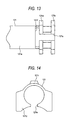
- Fig. 12 is a side view of the flange side of an outer jacket 121 viewed from side according to a second embodiment of this invention.
- Fig. 13 is a bottom view of the flange side of the outer jacket 121 viewed from bottom according to the second embodiment.
- Fig. 14 is a view of the configuration taken in line XIV-XIV in Fig. 11.
- the notch 121f which leads to a slit 121e has a shape which is narrow in the width in the axial direction.
- a rib 121r extending in the axial direction is provided on the outer periphery of the outer jacket 121 opposite to the slit 121e. The provision of such a rib 121r serves to reinforce the portion which is fragile for the stress concentration due to narrowing the width of the notch 121f, thereby restraining possibility of large-scaling the outer jacket 21.
- the rib 121r maybe adopted together with the notch having the shape shown in Fig. 5, 9 or 11.
- the sectional shape of the rib 121r in this embodiment should not be limited to a trapezoid shown in Fig. 14, but may be any shape such as a rectangular or semi-circular shape capable of restraining the interference with a peripheral component(s).
- the remaining structure whichmaybe identical to that in the embodiment described above, will not be explained here.
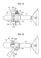
- Fig. 15 is a top view of a tilt-telescopic steering apparatus according to a third embodiment of this invention.
- Fig. 16 is a side view of a tilt-telescopic steering apparatus according to the third embodiment.
- Fig. 17 is a view taken in line XVII-XVII in Fig. 16 when viewed in the arrow direction.
- an inner column 11 shiftable in an axial direction is arranged within an outer jacket 221 is attached to a vehicle body (not shown) through a bracket 212.
- a steering shaft S is arranged within the inner column 11.
- a steering wheel H is attached to the right end of the steering shaft S in Fig. 15, a steering wheel H is attached.
- the left end of the steering shaft S is coupled with a pinion (tooth-engaged with the rack shaft of the steering apparatus) through e. g. a universal joint.
- the outer jacket 221 may incorporate a power unit for assisting steering power by supplying assisting power of an electric motor to the steering shaft.
- an attached bracket 12 has a structure in which bracket segments 212a, 212a extending in parallel in a vertical direction are coupled by a coupling plate 212d, the bracket segments having a pair of body attaching holes 212c (formed in a pair of body attaching planes 12e, respectively) which are employed to attach the bracket 12 to a vehicle body (not shown).
- the attached bracket 12 is made by bending a single plate material or welding a plurality of plate materials.
- the respective bracket segments 212a, 212a has equal plate thicknesses and shapes which are line-symmetrical with respect to a vertical line passing a steering axis.
- Each bracket segment 212a has a tilting groove 212b which serves as a part of the arc around the pivoting point (not shown) of the outer jacket 221.
- the body attaching hole 212c is displaced backward of the vehicle from the axial line of a fixing member 217 (described later) in the axial line of the inner column 11.
- the end 212f of the bracket segment 212a on the side of the tilting groove 212b with the body attaching hole 212c is bent to improve the rigidity.
- the outer jacket 221 is arranged between the bracket segments 212a and212a. At the lower portion of the outer jacket 221, a slit 221e is formed to extend in the axial direction. A through-hole 221n is formed to cross the slit 221e.
- the fixing member 217 which is headed, inserted into the tilting groove 212b of the bracket segment 212b from the left side in Fig. 17 is passed through the through-hole 221n formed in the bracket segment 212a on the left side in Fig. 17 and the outer jacket 221 and projects from the tilting groove 212b on the opposite side.
- a fixed cam 218 which consists of a tilt-guiding segment 18a having an elliptical section engaged to the width of the tilting groove 212b and fixed cam segment 218b having a larger diameter than the width
- a movable cam 219 having a cam face to be engaged to the fixed cam segment 218b
- an operating lever 220 which rotates integrally to the fixed cam 219
- a thrust bearing 222 which may be a rolling or a sliding bearing.
- the fixed cam 218, movable cam 219, bracket segments 212a, 212a constitute an urging member defined in claims.
- the fixing member 17, nut 23 and fixing member 16 functions as a fixing member.
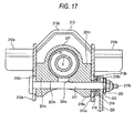
- Fig. 18 is a side view of the outer jacket 221 viewed from the side.
- Fig. 19 is a bottom view of the outer jacket 221 viewed from the bottom.
- the outer jacket 221 has, on the right end side thereof in Fig. 18 (on the side of the steering wheel side), pressing segments 221c which extend in a radial direction from the lower half of the outer periphery of the cylindrical portion 221a of the outer jacket 221 and are kept in contact with the bracket segments 212a, 212a.
- Recess 221f formed to be adjacent to the pressing segments 221c lead to a slit 221e which extends over the pressing segments 221c.
- the notch 221f has a tapered shape which expands toward the opening side (lower side) .
- Such a shape of the notch 221 is similar to that in the embodiment shown in Fig. 5.
- the outer jacket 221 is deformed in the direction of opening the slit 221e.
- the inner diameter of the outer jacket 221 is increased, thereby allowing movement of the inner column 11 in the telescopic direction (placed in the state where the inner column in the axial direction is shiftable/adjustable).
- the friction force between the outer jacket 221 and the brackets 212a, 212a is attenuated so that the movement of the inner column 211 along the tiling grooves 212b in the tilting direction is also allowed.
- the outer jacket 221 since the outer jacket 221 has the slit 221e, the end rigidity of the outer jacket 221 is reduced so that the diameter of the outer jacket 221 can be easily decreased, thereby enhancing the holding force of the inner column 11. Further, as seen from Figs. 18 and 19, since the notch 221f having the suitable shape are provided, the stress concentration when the pressing segments 221c are urged by the bracket segments 12a, 12a canbe alleviated, thereby effectively restraining the large-scaling of the outer jacket 221.
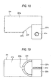
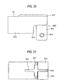
- Fig. 20 is a side view of an outer jacket 321 viewed from the side.
- Fig. 21 is a bottom view of the outer jacket 321 viewed from the bottom.
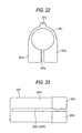
- Fig. 22 is a view when viewed in arrow XXII in Fig. 20.
- the notch 321f unlike the embodiment illustrated in Figs. 18 and 19, has a shape which is narrow in the width in the axial direction.
- a slit 321e extends in the axial direction to cross the notch 321f.
- a rib 321r extending in the axial direction is provided on the outer periphery of the outer jacket 321 opposite to the slit 321e. The provision of such a rib 321r serves to reinforce the portion which is fragile for the stress concentration due to narrowing the width of the notch 321f, thereby restraining possibility of large-scaling the inner column 11.
- the rib 321r may be adopted together with the notch having the shape shown in Fig. 18 and others.
- the sectional shape of the rib 321r in this embodiment should not be limited to a trapezoid shown in Fig. 22, but may be any shape such as a rectangular or semi-circular shape which restrains the interference with a peripheral component (s).
- the remaining structure whichmaybe identical to that in the embodiment shown in Figs. 15 to 19, will not be explained here.
- the shape of the notch of the outer jacket should not be limited to those described above.
- the notch 321f can be regarded as an extension of a slit 321.
- the function of alleviating the stress concentration is attenuated so that the notch 321 f is preferably made as long as possible.
- the notch 321f may be extended along the entire length of the outer jacket 321' .
- the slit was located on the lower side of the outer jacket, the slit may be located at the upper side of the outer jacket.
- the sectional shape of the flange is upside down from the case in the above embodiments.
- the outer jacket was arranged on the lower side whereas the inner column was arranged on the upper side, a layout may be adopted in which the outer jacket was arranged on the upper side whereas the inner column was arranged on the lower side.
- the outer jacket includes a pressed portion which extends in a direction leaving the axial line from the outer periphery of the outer jacket and is urged by the urging member, a slit which extends in the axial line direction over the pressed portion from the end of the outer jacket, and a notch which leads to the slit extending over the pressed portion; and the notch has a tapered shape which enlarges toward the opening side when the outer jacket is viewed in an urging direction of the urging member.
- the notch is provided, stress concentration when the pressed portion is urged by the urging member can be alleviated, thereby effectively restraining the large-scaling of the outer jacket.
- the notch has a tapered shape which enlarges toward the opening side, even when the outer jacket is largely deformed, the possibility of its large-scaling can be restrained.
- the outer jacket includes a pressed portion which extends in a direction leaving an axial line from the outer periphery of the outer jacket and is urged by the urging member, a slit which extends in the axial line direction over the pressed portion from the end of the outer jacket, a notch which leads to the slit extending over the pressed portion and a rib extending in the axial direction on the outer periphery opposite to the slit with respect to the axial line of the outer jacket.
- the rigidity of the outer jacket is reduced so that the diameter of the outer jacket can be easily decreased.
- the notch is provided, stress concentration when the pressed portion is urged by the urging member can be alleviated, thereby effectively restraining the large-scaling of the outer jacket.
- the rib extending in the axial direction is provided on the outer periphery opposite to the slit with respect to the axial line, the portion which is fragile for the stress is reinforced, thereby restraining possibility of large-scaling the outer jacket.
- the center of the slit is at an angle of 0° on the section orthogonal to the axial line of the outer jacket, the notch is formed within a range of ⁇ 90° from the center of the slit.
- Such a configuration serves to further restrain the possibility of large-scaling the outer jacket.
- the outer jacket includes the flange which extends in a direction leaving the axial line from the outer periphery of the outer jacket and is pressed by the pair of bracket segments, a slit which extends in the direction of the axial line from the end of the outer jacket to cross the flange and a notch which leads to the slit extending over the pressed portion; and the notch has a tapered shape which enlarges toward the opening side when the outer jacket is viewed from the bracket segments.
- the rigidity of the outer jacket is reduced so that the diameter of the outer jacket can be easily decreased.
- the notch is provided, stress concentration when the flange is urged by the bracket segments can be alleviated, thereby effectively restraining the large-scaling of the outer jacket.
- the notch has a tapered shape which enlarges toward the opening side, even when the outer jacket is largely deformed, the possibility of its large-scaling can be restrained.
- the outer jacket includes the flange which extends in a direction leaving the axial line from the outer periphery of the outer jacket and is pressed by the pair of bracket segments, a slit which extends in the axial direction from the end of the outer jacket to cross the flange, a notch which leads to the slit extending over the pressed portion and a rib extending in the axial direction on the outer periphery opposite to the slit with respect to the axial line of the outer jacket.
- the rigidity of the outer jacket is reduced so that the diameter of the outer jacket can be easily decreased.
- the notch is provided, stress concentration when the flange is urged by the bracket segments can be alleviated, thereby effectively restraining the large-scaling of the outer jacket.
- the rib extending in the axial direction is provided on the outer periphery opposite to the slit with respect to the axial line, the portion which is fragile for the stress is reinforced, thereby restraining possibility of large-scaling the outer jacket.
- the center of the slit is at an angle of 0° on the section orthogonal to the axial line of the outer jacket, the notch is formed within a range of ⁇ 90° from the center of the slit.
- Such a configuration serves to further restrain the possibility of large-scaling the outer jacket.
Claims (8)
- Ein Lenkapparat umfassend:eine innere Säule, welche einen Lenkschaft drehbar lagert;einen äußeren Mantel, welcher die innere Säule verstellbar in einer axialen Richtung aufnimmt, wobei zumindest ein Abschnitt des äußeren Mantels zylindrisch ist; undein Verdrängungselement zum Verdrängen der inneren Säule;wobei der äußere Mantel umfasst:einen gedrückten Abschnitt, welcher sich in einer Richtung erstreckt, die eine axiale Linie vom äußeren Umfang des äußeren Mantels verlässt und der von dem Verdrängungselement verdrängt wird,einen Schlitz, welcher sich in der axialen Richtung über den gedrückten Abschnitt vom Ende des äußeren Mantels erstreckt, undeine Einkerbung, welche zu dem Schlitz führt, der sich über den gedrückten Abschnitt erstreckt; undwobei die Einkerbung eine zugespitzte Form aufweist, welche sich in Richtung einer Öffnungsseite vergrößert, wenn der äußere Mantel in einer Verdrängungsrichtung des Verdrängungselementes betrachtet wird.
- Der Lenkapparat nach Anspruch 1, wobei, in der Annahme, dass die Mitte des Schlitzes an dem Abschnitt orthogonal zur axialen Linie des äußeren Mantels in einem Winkel von 0° angeordnet ist, die Einkerbung in einem Bereich von ±90° von der Mitte des Schlitzes ausgebildet ist.
- Ein Lenkapparat, umfassend:eine innere Säule, welche einen Lenkschaft drehbar lagert;einen äußeren Mantel, welcher die innere Säule verstellbar in einer axialen Richtung aufnimmt, wobei zumindest ein Abschnitt des äußeren Mantels zylindrisch ist; undein Verdrängungselement zum Verdrängen der inneren Säule;wobei der äußere Mantel umfasst:einen gedrückten Abschnitt, welcher sich in einer Richtung erstreckt, welche eine axiale Linie vom äußeren Umfang des äußeren Mantels verlässt und welcher von dem Verdrängungselement verdrängt wird,einen Schlitz, welcher sich vom Ende des äußeren Mantels in der axialen Richtung über den gedrückten Abschnitt erstreckt,eine Einkerbung, welche zu dem Schlitz führt, welcher sich über den gedrückten Abschnitt erstreckt, undeine Rippe, welche sich am äußeren Umfang in der axialen Richtung erstreckt, entgegengesetzt zu dem Schlitz mit Bezug auf die axiale Linie.
- Der Lenkapparat nach Anspruch 3, wobei, in der Annahme, dass die Mitte des Schlitzes an dem Abschnitt orthogonal zur axialen Linie des äußeren Mantels in einem Winkel von 0° angeordnet ist, die Einkerbung in einem Bereich von ±90° von der Mitte des Schlitzes ausgebildet ist.
- Ein Lenkapparat zum Lagem eines Lenkschaftes, der verstellbar in einer axialen Richtung an einem Lenkrad angebracht ist, umfassend:eine innere Säule, welche den Lenkschaft drehbar lagert,ein Paar von Haltersegmenten, angebracht an einem Fahrzeugkörper und angeordnet in entgegengesetzten Positionen in Bezug auf eine axiale Linie des Lenkschaftes;ein Anspannungselement, welches sich zwischen dem Paar von Haltersegmenten erstreckt;zwei Fixierelemente zum Fixieren des Anspannungselements von der Außenseite des Paars der Haltersegmente;ein Verschiebungsausübungselement, angeordnet zwischen dem Anspannungselement und den Fixierelementen zum Ausüben einer relativen Verschiebung zwischen den Haltersegmenten und den Fixierelementen in Verriegelung mit einer Bewegung eines Betätigungshebels; undein zylindrischer äußerer Mantel, der durch Kopplung des Anspannungselements, der Haltersegmente und des Fixierelements am Fahrzeugkörper gehalten wird und der einen Flansch aufweist, wobei ein äußerer Umfang mit den Haltersegmenten in Kontakt zu bringen ist durch die relative Verschiebung der Haltersegmente zumindest zwischen dem Paar von Haltersegmenten, und wobei ein innerer Umfang den äußeren Umfang der inneren Säule umhüllt,wobei das Paar der Haltersegmente sich durch die relative Verschiebung, die von dem Ausübungselement vorgegeben wird, aneinander annähert, so dass durch den Flansch des äußeren Mantels eine Druckkraft auf die innere Säule ausgeübt wird, so dass die innere Säule mit den Haltersegmenten durch den äußeren Mantel hindurch in ihrer axialen Position gehalten wird;
wobei der äußere Mantel umfasst: den Flansch, welcher sich in einer Richtung erstreckt, welche die axiale Linie vom äußeren Umfang des äußeren Mantels verlässt und welcher mit dem Paar von Haltersegmenten gedrückt wird, einen Schlitz, welcher sich vom Ende des äußeren Mantels in der axialen Richtung erstreckt, um den Flansch zu kreuzen, und eine Einkerbung, welche zu dem Schlitz führt, der sich über den gedrückten Abschnitt erstreckt; und wobei die Einkerbung eine zugespitzte Form aufweist, welche sich in Richtung der Öffnungsseite vergrößert, wenn der äußere Mantel von den Haltersegmenten aus betrachtet wird. - Der Lenkapparat nach Anspruch 5, wobei, in der Annahme, dass die Mitte des Schlitzes an dem Abschnitt orthogonal zur axialen Linie des äußeren Mantels in einem Winkel von 0° angeordnet ist, die Einkerbung in einem Bereich von ±90° von der Mitte des Schlitzes ausgebildet ist.
- Ein Lenkapparat zum Lagem eines Lenkschaftes, der in einer axialen Richtung verstellbar an einem Lenkrad angebracht ist, umfassend:eine innere Säule, welche den Lenkschaft drehbar lagert;ein Paar von Haltersegmenten, angebracht an einem Fahrzeugkörper und angeordnet in entgegengesetzten Positionen mit Bezug auf eine axiale Linie des Lenkschaftes;ein Anspannungselement, welches sich zwischen dem Paar von Haltersegmenten erstreckt;zwei Fixierelemente, um das Anspannungselement von der Außenseite des Paars von Haltersegmenten zu fixieren;ein Verschiebungsausübungselement, angeordnet zwischen dem Anspannungselement und den Fixierelementen zum Ausüben einer relativen Verschiebung zwischen den Haltersegmenten und den Fixierelementen in Verriegelung mit einer Bewegung eines Betätigungshebels; undeinen zylindrischen äußeren Mantel, der durch Kopplung des Verspannungselements, der Haltersegmente und des Fixierelements am Fahrzeugkörper gehalten wird und der einen Flansch aufweist, wobei ein äußerer Umfang mit den Haltersegmenten in Kontakt zu bringen ist durch die relative Verschiebung der Haltersegmente zumindest zwischen dem Paar von Haltersegmenten, und wobei ein innerer Umfang den äußeren Umfang der inneren Säule umhüllt;wobei sich das Paar von Haltersegmenten durch die relative Verschiebung, die von dem Ausübungselement ausgeübt wird, aneinander annähert, so dass durch den Flansch des äußeren Mantels eine Druckkraft auf die innere Säule aufgeübt wird, wobei die innere Säule mit den Haltersegmenten durch den äußeren Mantel hindurch in ihrer axialen Position gehalten wird;
wobei der äußere Mantel umfasst: den Flansch, welcher sich in einer Richtung erstreckt, welche die axiale Linie vom äußeren Umfang des äußeren Mantels verlässt und welcher von dem Paar von Haltersegmenten gedrückt wird, einen Schlitz, welcher sich vom Ende des äußeren Mantels in der axialen Richtung erstreckt, um den Flansch zu kreuzen, eine Einkerbung, welche zu dem Schlitz führt, welcher sich über den gedrückten Abschnitt erstreckt und eine Rippe, welche sich in der axialen Richtung am äußeren Umfang erstreckt, entgegengesetzt zu dem Schlitz mit Bezug auf die axiale Linie. - Der Lenkapparat nach Anspruch 7, wobei, in der Annahme, dass die Mitte des Schlitzes an dem Abschnitt orthogonal zur axialen Linie des äußeren Mantels in einem Winkel von 0° angeordnet ist, die Einkerbung in einem Bereich von ±90° von der Mitte des Schlitzes ausgebildet ist.
Applications Claiming Priority (2)
| Application Number | Priority Date | Filing Date | Title |
|---|---|---|---|
| JP2003375095 | 2003-11-05 | ||
| JP2003375095A JP4390134B2 (ja) | 2003-11-05 | 2003-11-05 | ステアリング装置 |
Publications (3)
| Publication Number | Publication Date |
|---|---|
| EP1529713A2 EP1529713A2 (de) | 2005-05-11 |
| EP1529713A3 EP1529713A3 (de) | 2005-08-10 |
| EP1529713B1 true EP1529713B1 (de) | 2007-01-17 |
Family
ID=34431269
Family Applications (1)
| Application Number | Title | Priority Date | Filing Date |
|---|---|---|---|
| EP04026218A Expired - Fee Related EP1529713B1 (de) | 2003-11-05 | 2004-11-04 | Lenkapparat |
Country Status (4)
| Country | Link |
|---|---|
| US (1) | US7354069B2 (de) |
| EP (1) | EP1529713B1 (de) |
| JP (1) | JP4390134B2 (de) |
| DE (1) | DE602004004343T8 (de) |
Families Citing this family (28)
| Publication number | Priority date | Publication date | Assignee | Title |
|---|---|---|---|---|
| JP4390135B2 (ja) * | 2003-11-07 | 2009-12-24 | 日本精工株式会社 | ステアリング装置 |
| CN101200195B (zh) * | 2004-07-27 | 2010-10-27 | 日本精工株式会社 | 转向柱装置 |
| GB0517781D0 (en) * | 2005-09-01 | 2005-10-12 | Trw Lucasvarity Electric Steer | Steering column assembly |
| JP4951258B2 (ja) * | 2006-03-29 | 2012-06-13 | 富士機工株式会社 | ステアリングコラム装置 |
| KR100848500B1 (ko) * | 2007-01-31 | 2008-07-28 | 주식회사 만도 | 틸트 및 텔레스코프 조향장치 |
| JP5092880B2 (ja) * | 2007-05-17 | 2012-12-05 | 日本精工株式会社 | ステアリング装置 |
| GB0714161D0 (en) * | 2007-07-20 | 2007-08-29 | Trw Ltd | Steering column assembly |
| JP2009233815A (ja) * | 2008-03-28 | 2009-10-15 | Ihi Corp | 台座の補強構造及び台座の補強方法 |
| JP5279741B2 (ja) * | 2009-03-30 | 2013-09-04 | 株式会社山田製作所 | ステアリング装置 |
| KR101268248B1 (ko) * | 2009-07-09 | 2013-05-31 | 주식회사 만도 | 자동차의 조향 컬럼 |
| JP5662115B2 (ja) * | 2010-01-20 | 2015-01-28 | 株式会社山田製作所 | ステアリング装置 |
| JP5279743B2 (ja) * | 2010-02-19 | 2013-09-04 | 株式会社山田製作所 | ステアリング位置調整装置 |
| GB201110277D0 (en) | 2011-06-17 | 2011-08-03 | Trw Ltd | A clamp assembly for a steering column assembly |
| KR20130027122A (ko) | 2011-09-07 | 2013-03-15 | 주식회사 만도 | 자동차의 조향 컬럼 및 이를 포함하는 자동차의 조향장치 |
| GB201208791D0 (en) | 2012-05-18 | 2012-07-04 | Trw Ltd | Steering column assembly |
| DE102012104644B3 (de) * | 2012-05-30 | 2013-08-08 | Thyssenkrupp Presta Aktiengesellschaft | Lenksäule für ein Kraftfahrzeug |
| JP5787036B2 (ja) * | 2013-02-13 | 2015-09-30 | 日本精工株式会社 | アウタコラム |
| US8997603B2 (en) * | 2013-03-14 | 2015-04-07 | Steering Solutions Ip Holding Corporation | Steering column assembly with improved attachment to a vehicle structure |
| JP6343177B2 (ja) * | 2014-05-23 | 2018-06-13 | 株式会社ミツバ | ワイパアーム |
| DE102015000027A1 (de) * | 2015-01-08 | 2016-07-14 | Thyssenkrupp Ag | Lenksäule mit flexibel montierbarem Lagersitz |
| JP6497543B2 (ja) * | 2015-01-22 | 2019-04-10 | 株式会社ジェイテクト | ステアリング装置 |
| JP6527001B2 (ja) * | 2015-03-31 | 2019-06-05 | 富士機工株式会社 | ステアリングコラム装置 |
| JP6142967B2 (ja) * | 2015-05-19 | 2017-06-07 | 日本精工株式会社 | テレスコピック式ステアリング装置 |
| GB2566704A (en) * | 2017-09-21 | 2019-03-27 | Ford Global Tech Llc | A steering assembly |
| US11034377B2 (en) * | 2018-07-31 | 2021-06-15 | Steering Solutions Ip Holding Corporation | System and method of automatically stowing and unstowing a steering column assembly |
| US11292504B2 (en) * | 2019-03-20 | 2022-04-05 | Volvo Car Corporation | Vehicle having multiple driving positions |
| JP7351684B2 (ja) * | 2019-09-13 | 2023-09-27 | 株式会社ジェイテクト | ステアリングコラム装置 |
| US11345390B2 (en) * | 2020-03-27 | 2022-05-31 | Yamada Manufacturing Co., Ltd. | Steering device |
Family Cites Families (17)
| Publication number | Priority date | Publication date | Assignee | Title |
|---|---|---|---|---|
| FR2588047B1 (fr) | 1985-09-30 | 1988-01-08 | Peugeot Cycles | Dispositif de fixation pour une piece tubulaire en particulier pour une colonne de direction de vehicule |
| JP3335485B2 (ja) | 1994-09-13 | 2002-10-15 | 富士機工株式会社 | 車両用ステアリングコラム |
| GB2295445A (en) | 1994-11-24 | 1996-05-29 | Torrington Co | Adjustable steering column |
| JP3440605B2 (ja) | 1995-02-27 | 2003-08-25 | 日本精工株式会社 | チルト式ステアリング装置 |
| LV11728B (en) | 1995-08-21 | 1997-08-20 | Kalvins Ivars | Pharmaceutical composition |
| FR2787842B1 (fr) * | 1998-12-29 | 2001-02-23 | Lemforder Nacam Sa | Dispositif de serrage en trois points d'un systeme de reglage en position d'un element par rapport a un autre element |
| US6139057A (en) | 1999-02-04 | 2000-10-31 | Delphi Technologies, Inc. | Position control apparatus for steering column |
| DE10026671A1 (de) * | 1999-06-05 | 2001-01-18 | Delphi Tech Inc | Klemmvorrichtung für eine Lenksäule |
| GB2352286A (en) * | 1999-07-19 | 2001-01-24 | Delphi Tech Inc | Clamping device for a steering column |
| JP2001191927A (ja) | 2000-01-13 | 2001-07-17 | Nsk Ltd | 車両用ステアリング装置 |
| JP4613402B2 (ja) | 2000-02-15 | 2011-01-19 | 日本精工株式会社 | 車両用ステアリング装置 |
| EP1125820B2 (de) * | 2000-02-15 | 2012-07-11 | Nsk Ltd | Lenkung für ein Automobil |
| JP2002059848A (ja) | 2000-08-16 | 2002-02-26 | Nsk Ltd | 車両用ステアリング装置 |
| JP2002059850A (ja) | 2000-08-23 | 2002-02-26 | Nsk Ltd | 車両用ステアリング装置 |
| JP4470302B2 (ja) | 2000-09-11 | 2010-06-02 | 日本精工株式会社 | 車両用ステアリング装置 |
| JP4147579B2 (ja) | 2002-01-17 | 2008-09-10 | 日本精工株式会社 | ステアリング装置 |
| AU2003227417A1 (en) | 2002-05-10 | 2003-11-11 | Nsk Ltd. | Steering device |
-
2003
- 2003-11-05 JP JP2003375095A patent/JP4390134B2/ja not_active Expired - Fee Related
-
2004
- 2004-11-04 DE DE602004004343T patent/DE602004004343T8/de not_active Expired - Fee Related
- 2004-11-04 EP EP04026218A patent/EP1529713B1/de not_active Expired - Fee Related
- 2004-11-04 US US10/980,777 patent/US7354069B2/en active Active
Also Published As
| Publication number | Publication date |
|---|---|
| DE602004004343T2 (de) | 2007-05-10 |
| US7354069B2 (en) | 2008-04-08 |
| DE602004004343D1 (de) | 2007-03-08 |
| DE602004004343T8 (de) | 2008-01-10 |
| EP1529713A2 (de) | 2005-05-11 |
| US20050093283A1 (en) | 2005-05-05 |
| JP2005138644A (ja) | 2005-06-02 |
| EP1529713A3 (de) | 2005-08-10 |
| JP4390134B2 (ja) | 2009-12-24 |
Similar Documents
| Publication | Publication Date | Title |
|---|---|---|
| EP1529713B1 (de) | Lenkapparat | |
| EP3257725B1 (de) | Teleskopische lenksäule und lenkvorrichtung | |
| US10059363B2 (en) | Steering device | |
| JP5152548B2 (ja) | 車両用操舵装置 | |
| US8813594B2 (en) | Rack and pinion steering gear unit | |
| EP3257721B1 (de) | Teleskopische lenkvorrichtung | |
| US10093340B2 (en) | Steering device | |
| US20030164608A1 (en) | Automotive steering system | |
| JP2003276614A (ja) | ステアリング装置 | |
| US9889875B2 (en) | Steering column device | |
| JP2005047487A (ja) | ステアリング装置 | |
| EP1529714A2 (de) | Lenksäulen-Klemmvorrichtung | |
| WO2005037627A1 (ja) | ステアリング装置 | |
| JP7405703B2 (ja) | ステアリングコラム装置 | |
| JP6403334B2 (ja) | ステアリング装置 | |
| JP2009090737A (ja) | ステアリングコラム装置 | |
| JP2009292429A (ja) | 車両のステアリング装置 | |
| JP7279581B2 (ja) | カム装置及びステアリング装置 | |
| JP6935698B2 (ja) | ステアリング装置 | |
| JP2022145498A (ja) | ステアリング装置 | |
| JP6972760B2 (ja) | ステアリング装置 | |
| JP2006182203A (ja) | ステアリング装置 | |
| JP2005067451A (ja) | ステアリング装置 | |
| JP2016016734A (ja) | ステアリング装置 |
Legal Events
| Date | Code | Title | Description |
|---|---|---|---|
| PUAI | Public reference made under article 153(3) epc to a published international application that has entered the european phase |
Free format text: ORIGINAL CODE: 0009012 |
|
| AK | Designated contracting states |
Kind code of ref document: A2 Designated state(s): AT BE BG CH CY CZ DE DK EE ES FI FR GB GR HU IE IS IT LI LU MC NL PL PT RO SE SI SK TR |
|
| AX | Request for extension of the european patent |
Extension state: AL HR LT LV MK YU |
|
| PUAL | Search report despatched |
Free format text: ORIGINAL CODE: 0009013 |
|
| AK | Designated contracting states |
Kind code of ref document: A3 Designated state(s): AT BE BG CH CY CZ DE DK EE ES FI FR GB GR HU IE IS IT LI LU MC NL PL PT RO SE SI SK TR |
|
| AX | Request for extension of the european patent |
Extension state: AL HR LT LV MK YU |
|
| GRAP | Despatch of communication of intention to grant a patent |
Free format text: ORIGINAL CODE: EPIDOSNIGR1 |
|
| 17P | Request for examination filed |
Effective date: 20051103 |
|
| AKX | Designation fees paid |
Designated state(s): DE FR GB |
|
| GRAS | Grant fee paid |
Free format text: ORIGINAL CODE: EPIDOSNIGR3 |
|
| GRAA | (expected) grant |
Free format text: ORIGINAL CODE: 0009210 |
|
| AK | Designated contracting states |
Kind code of ref document: B1 Designated state(s): DE FR GB |
|
| RAP1 | Party data changed (applicant data changed or rights of an application transferred) |
Owner name: NSK STEERING SYSTEMS CO., LTD. Owner name: NSK LTD. |
|
| REG | Reference to a national code |
Ref country code: GB Ref legal event code: FG4D |
|
| REF | Corresponds to: |
Ref document number: 602004004343 Country of ref document: DE Date of ref document: 20070308 Kind code of ref document: P |
|
| ET | Fr: translation filed | ||
| PLBE | No opposition filed within time limit |
Free format text: ORIGINAL CODE: 0009261 |
|
| STAA | Information on the status of an ep patent application or granted ep patent |
Free format text: STATUS: NO OPPOSITION FILED WITHIN TIME LIMIT |
|
| 26N | No opposition filed |
Effective date: 20071018 |
|
| PGFP | Annual fee paid to national office [announced via postgrant information from national office to epo] |
Ref country code: DE Payment date: 20081103 Year of fee payment: 5 |
|
| PGFP | Annual fee paid to national office [announced via postgrant information from national office to epo] |
Ref country code: FR Payment date: 20081112 Year of fee payment: 5 |
|
| PGFP | Annual fee paid to national office [announced via postgrant information from national office to epo] |
Ref country code: GB Payment date: 20081029 Year of fee payment: 5 |
|
| GBPC | Gb: european patent ceased through non-payment of renewal fee |
Effective date: 20091104 |
|
| REG | Reference to a national code |
Ref country code: FR Ref legal event code: ST Effective date: 20100730 |
|
| PG25 | Lapsed in a contracting state [announced via postgrant information from national office to epo] |
Ref country code: FR Free format text: LAPSE BECAUSE OF NON-PAYMENT OF DUE FEES Effective date: 20091130 |
|
| PG25 | Lapsed in a contracting state [announced via postgrant information from national office to epo] |
Ref country code: DE Free format text: LAPSE BECAUSE OF NON-PAYMENT OF DUE FEES Effective date: 20100601 |
|
| PG25 | Lapsed in a contracting state [announced via postgrant information from national office to epo] |
Ref country code: GB Free format text: LAPSE BECAUSE OF NON-PAYMENT OF DUE FEES Effective date: 20091104 |