EP1529639B1 - Transportsystem in einer Bedruckstoff verarbeitenden Maschine und Verfahren zur Herstellung eines Primärteils eines elektrischen Linearantriebs - Google Patents
Transportsystem in einer Bedruckstoff verarbeitenden Maschine und Verfahren zur Herstellung eines Primärteils eines elektrischen Linearantriebs Download PDFInfo
- Publication number
- EP1529639B1 EP1529639B1 EP20040105466 EP04105466A EP1529639B1 EP 1529639 B1 EP1529639 B1 EP 1529639B1 EP 20040105466 EP20040105466 EP 20040105466 EP 04105466 A EP04105466 A EP 04105466A EP 1529639 B1 EP1529639 B1 EP 1529639B1
- Authority
- EP
- European Patent Office
- Prior art keywords
- switch
- height
- transport system
- winding cores
- guide
- Prior art date
- Legal status (The legal status is an assumption and is not a legal conclusion. Google has not performed a legal analysis and makes no representation as to the accuracy of the status listed.)
- Expired - Lifetime
Links
- 238000007639 printing Methods 0.000 title claims description 40
- 238000004519 manufacturing process Methods 0.000 title claims description 11
- 238000000034 method Methods 0.000 title claims description 10
- 239000000463 material Substances 0.000 title claims description 9
- 238000004804 winding Methods 0.000 claims description 65
- 238000012545 processing Methods 0.000 claims description 13
- 238000000227 grinding Methods 0.000 claims description 2
- 238000003801 milling Methods 0.000 claims description 2
- 230000008569 process Effects 0.000 claims description 2
- 238000004080 punching Methods 0.000 claims description 2
- 238000003754 machining Methods 0.000 claims 2
- 230000032258 transport Effects 0.000 description 64
- 239000000758 substrate Substances 0.000 description 11
- 230000004907 flux Effects 0.000 description 9
- 230000008901 benefit Effects 0.000 description 7
- 238000010586 diagram Methods 0.000 description 5
- 238000004364 calculation method Methods 0.000 description 4
- 238000004088 simulation Methods 0.000 description 4
- 238000012546 transfer Methods 0.000 description 4
- 238000005452 bending Methods 0.000 description 3
- 238000005520 cutting process Methods 0.000 description 3
- 238000011144 upstream manufacturing Methods 0.000 description 3
- 241000114304 Laterallus jamaicensis Species 0.000 description 2
- 239000004744 fabric Substances 0.000 description 2
- 238000004806 packaging method and process Methods 0.000 description 2
- 238000012805 post-processing Methods 0.000 description 2
- 230000001105 regulatory effect Effects 0.000 description 2
- 241000531809 Laterallus Species 0.000 description 1
- 238000004026 adhesive bonding Methods 0.000 description 1
- 230000008859 change Effects 0.000 description 1
- 239000011248 coating agent Substances 0.000 description 1
- 238000000576 coating method Methods 0.000 description 1
- 230000008878 coupling Effects 0.000 description 1
- 238000010168 coupling process Methods 0.000 description 1
- 238000005859 coupling reaction Methods 0.000 description 1
- 238000013461 design Methods 0.000 description 1
- 238000011161 development Methods 0.000 description 1
- 230000018109 developmental process Effects 0.000 description 1
- 230000005672 electromagnetic field Effects 0.000 description 1
- 239000000696 magnetic material Substances 0.000 description 1
- 239000007769 metal material Substances 0.000 description 1
- 238000007645 offset printing Methods 0.000 description 1
- 239000004033 plastic Substances 0.000 description 1
- 230000011218 segmentation Effects 0.000 description 1
- 238000000926 separation method Methods 0.000 description 1
Images


Classifications
-
- H—ELECTRICITY
- H02—GENERATION; CONVERSION OR DISTRIBUTION OF ELECTRIC POWER
- H02K—DYNAMO-ELECTRIC MACHINES
- H02K41/00—Propulsion systems in which a rigid body is moved along a path due to dynamo-electric interaction between the body and a magnetic field travelling along the path
- H02K41/02—Linear motors; Sectional motors
- H02K41/03—Synchronous motors; Motors moving step by step; Reluctance motors
-
- B—PERFORMING OPERATIONS; TRANSPORTING
- B41—PRINTING; LINING MACHINES; TYPEWRITERS; STAMPS
- B41F—PRINTING MACHINES OR PRESSES
- B41F13/00—Common details of rotary presses or machines
- B41F13/004—Electric or hydraulic features of drives
- B41F13/0045—Electric driving devices
-
- H—ELECTRICITY
- H02—GENERATION; CONVERSION OR DISTRIBUTION OF ELECTRIC POWER
- H02K—DYNAMO-ELECTRIC MACHINES
- H02K3/00—Details of windings
- H02K3/04—Windings characterised by the conductor shape, form or construction, e.g. with bar conductors
- H02K3/18—Windings for salient poles
-
- B—PERFORMING OPERATIONS; TRANSPORTING
- B41—PRINTING; LINING MACHINES; TYPEWRITERS; STAMPS
- B41P—INDEXING SCHEME RELATING TO PRINTING, LINING MACHINES, TYPEWRITERS, AND TO STAMPS
- B41P2213/00—Arrangements for actuating or driving printing presses; Auxiliary devices or processes
- B41P2213/10—Constitutive elements of driving devices
- B41P2213/11—Motors
- B41P2213/124—Electric motors
- B41P2213/128—Linear electric motors
Definitions
- the present invention relates to a transport system in a printing machine using the features of the preamble of claim 1.
- the present invention relates to a method for producing a primary part of an electric linear drive with the features of the preamble of claim 9.
- the substrate to be processed for. B. substrate sheet (hereinafter arc) to transport by means of a transport system based on electric linear actuators.
- switches may be designed as mechanically active or mechanically passive switches, d. H. they comprise moving mechanical components, for example, for changing the travel path. B. rail sections, or not.
- document DE 196 21 507 Cl discloses a sheet-fed web retractor with a mechanically active switch.
- the device has a guide rail, in which a pulling device for pulling the web is movable, on.
- the propulsion is generated by an electric linear drive, which is a stator made of cores magnetizable material electromagnets each with it having wound coils.
- the cores can be connected to each other via pole plates.
- the linear drive also has as a runner on the drawbar on which two or more permanent magnets or closed, electrically excitable coils are attached.
- the pulling device can be designed as an elongated link chain whose length is greater than the distance between two adjacent drive stations designed as coils.
- the device also has one or more switchable points, which are each designed as a rotatable disc, on which in each case curved portions of the guide rail are arranged in different directions. Depending on the rotational position of the disc, a web path for the entry of the web can be adjusted.
- the switch described can only be used in conjunction with the drawbar designed as a link, since no drive stations are in the area of the switch, and thus the towing device must be drivingly detected by the switch before or downstream drive stations.
- the rotor of the drive forming propulsion elements of magnetic material, for. B. from permanent magnets.
- the drive stations forming the stator of the drive comprise known electromagnetic coils which generate an electromagnetic traveling field for propulsion of the propulsion elements.
- the transport system has a guide device with a mechanically passive switch, which can be formed, for example, by two additional drive stations, which are arranged at the beginning of a respective branching path of the transport system and which are energized alternately according to the path to be taken (ie targeted connection and disconnection of electromagnetic fields in parts of the transport path for generating cornering forces), whereby the propulsion elements are conveyed in one or the other path.
- a mechanically passive switch which can be formed, for example, by two additional drive stations, which are arranged at the beginning of a respective branching path of the transport system and which are energized alternately according to the path to be taken (ie targeted connection and disconnection of electromagnetic fields in parts of the transport path for generating cornering forces), whereby the propulsion elements are conveyed in one or the other path.
- the proposed solution has the problem that the proposed design of the switch as a mechanically passive switch, d. H. without moving components, although a fast switching of the switch and a undercut-free arrangement of the branching paths allowed, however, may be undesirably limited in terms of the guiding accuracy of the drive elements in the region of the switch compared to the rigid guide with mechanically active points.
- Such a system is in each case in the JP 59-6763 A and in the JP 5-140903 A described.
- the switchable switches described therein are designed so that not only guide devices, eg. B. rail sections are moved, but together with these, the stator of the drive.
- guide devices eg. B. rail sections are moved, but together with these, the stator of the drive.
- such a system has the problem that for switching or to place the switch massive elements must be moved so that a fast switching of the switch with short switching times does not seem possible.
- a slow shift appears acceptable in the area of passenger transport systems, as the individual features of the system have large distances to each other.
- the winding cores (or teeth) of the primary part are - as usual - arranged such that grooves are formed between the winding cores, in which the windings, which are placed around the hubs, are added.
- the transport system according to the invention has a specially designed primary part of the electric linear drive. According to the invention, at least one winding core in the region of the switch of lesser height than winding cores is outside the region of the switch.
- the provided by the lower height of the winding core recess in the primary part advantageously allows the inclusion of at least one guide segment, such as a rail section.
- a switch can be formed in the transport system by at the junction guide means, for. B. rails, are guided by the recess in the primary part.
- the rails are at least in the region of the recess advantageously made of non-metallic material, eg. B. plastic.
- Another advantage of the invention is found in that the runners of the linear drive, d. H. the carriages or carriages of the transport system, also in the area of the switch, are constantly under the driving influence of the electric linear drive and consequently a safe and precise guiding of the carriages is also made possible in the area of the switch.
- a transport system according to the invention thus provides a stiff and therefore accurate mechanical guidance, but also allows the fast path change by highly dynamically and independently switchable, segmented guide elements.
- a respective further advantage of the invention is the separation of the drive system (linear electric component) from the mechanical switching elements (segmented guide elements or rail pieces) the realization of switching times that are less than the transit times of a runner (wagon) through the switch and the Possibility of switching the switch even during the presence of a runner in the area of the switch.
- a transport system according to the invention can be used in sheet-fed printing machines, in particular in sheet-fed rotary printing presses, for transporting, conveying, feeding in and out of sheets.
- a transport system according to the invention can furthermore be used in web-fed printing presses, in particular in rotary offset rotary printing presses, for transporting, conveying or drawing in one or more webs.
- An inventive transport system can also be used in folders for transporting signatures or folded products.
- a transport system according to the invention can also be used in post-processing machines (postpress machines), in particular in gluing machines, binding machines, punches, stacking machines or packaging machines for transporting or conveying printed products.
- postpress machines post-processing machines
- gluing machines binding machines
- punches punches
- stacking machines packaging machines for transporting or conveying printed products.
- An inventive transport system can also be used in digital printing machines, especially in copying, for transporting or conveying of printing material.
- a transport system according to the invention can also be used in the pre-press stage (in prepress machines), in particular in platesetters, for transporting or conveying printing plates instead of printing material.
- An embodiment of the transport system according to the invention is characterized in that the winding cores are provided with windings only in a lower portion with respect to the height of winding cores outside the region of the switch. All winding cores or only winding cores in the region of the switch can be designed in this way.
- a transport system is characterized in that the hubs with respect to the height of hubs outside the area of the switch only in a lower portion of less than about 75% or 50% of the height, in particular less than about 40% or 30% or 25% of the height, are provided with windings.
- a preferred embodiment of the transport system according to the invention can be characterized in that the at least one guide segment is arranged stationarily in the recess.
- the transport system according to the invention is characterized in that the at least one guide segment at least partially in the recess or laterally to the recess zoom is movable, in particular linearly movable or pivotable configured.
- the at least one guide segment between a passive position and an active position is movable.
- a further guide segment between the active position and another passive position is movable.
- a method according to the invention for producing a primary part of an electric linear drive, in which a number of winding cores of the primary part are provided with windings, is characterized in that the number of winding cores is provided with windings only in a lower section with respect to their height and that at least one Winding core is made with a lower height.
- the method according to the invention advantageously allows the simple production of special primary parts of electric linear drives.
- Primary parts manufactured in this way can be used with advantage in transport systems, which are equipped with branches and switches arranged at the branches.
- the primary parts produced according to the invention permit the recessed space above the winding core of lesser height for guide devices, for As rails, so that the rails are passed through the primary part and can be found in this way the primary part in the area of a switch.
- a further advantage of the production method according to the invention can be found in the fact that primary parts for electric linear drives can be produced in a simple manner, which permit an uninterrupted and trouble-free driving of a rotor of the drive also in the region of points.
- an inventive method is characterized in that the number of hubs with respect to their height only in a lower portion of less than about 75% or 50% of the height, in particular less than about 40% or 30% or 25% of Height, is provided with windings.
- a preferred embodiment of the method according to the invention may be distinguished by the fact that the production of the smaller height of the at least one winding core takes place by cutting, in particular milling or grinding, or non-cutting, in particular punching.
- FIG. 1 shows a schematic side view of a printing unit 2 of a substrate 3 (eg., In the form of substrate sheet) processing printing machine 1.
- the printing unit 2 at least one unit 4, z. B. another printing unit or a sheet feeder, upstream and at least two units 6, 8, z.
- coating units, dryers, sheet delivery or post-processing facilities for example, cutting machines, folders, punches, binding machines or packaging stations, downstream.
- the printing unit has a inking and / or dampening unit 200 with rollers, a forme cylinder 202 with a clamped printing forme 203 (eg printing plate or printing sleeve), a transfer cylinder 204 with a mounted transfer cloth 205 (eg rubber blanket or rubber blanket sleeve) and an impression cylinder 206.
- the printing unit 2 may have a separate motor 208 for driving the cylinders and rollers or the printing unit may be driven by a common drive of several printing units.
- the printing machine 1 comprises a transport system 10 for the sheet 3, which extends along the transport path and which at least one guide device 12 and at least one along the guide device movable carriage 14, on which the sheet 3 are held.
- the carriages 14 are guided back to the unit 4 on a return section 16 of the transport system 10.
- the transport system may have opposing guide means on each side of the printing press which follow substantially the same path of the web for guiding the carriage 14.
- FIG. 1 It can be seen that the transport system has a switch 18, at which a first path 20 of the guide device 12 branches into a second and third path 22, 24 of the guide device 12. The switch is thus arranged at a branch of the transport path.
- FIG. 2 shows a sectional view of the transport system 10. It is shown for simplicity, only one side end portion of a carriage 14 and a leading end portion of this guide means 14 which z. B. can be arranged on a side wall of the printing machine 1 or 2 of the printing unit. However, the carriage can with its opposite further (not shown) lateral end portion also be guided in a guide device, which is preferably arranged on the opposite wall of the printing press or the printing unit.
- the guide device 12 of the transport system 10 comprises two mutually spaced rails 30, 32 (which extend in the figure in the plane), between which a primary part 34 of an electric linear motor 36 is arranged.
- the secondary part 38 of the electric linear motor 36 comprises the carriage 14 designed as a runner, a section 38 of the carriage 14 or an element 38 arranged on the carriage 14.
- the carriage 14 forms a section 38 of the carriage 14 or an element 38 arranged on the carriage 14 the secondary part 38 of the electric linear motor 36th
- the carriage 14 is supported on the rails 30, 32 via wheels 40, 42, 44, 46 in such a manner that the carriage is securely guided both in the vertical direction 47 and in the lateral direction 48 to the track, d. H. can perform essentially no movements, and in the direction of the rail track (in the figure in the drawing plane inside) is movable.
- the magnetic attraction forces between 38 and 34 act as an abutment to the wheels 44, 46th
- the carriage 14 has a traverse 49 on which gripper units 50 are arranged, the gripper units 50 holding the sheet 3 to be transported or processed between gripper pads 52 and movable grippers 54.
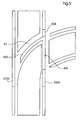
- FIG. 3 the transport system 10 according to the invention is shown in the region of the switch.
- the region of the switch can be understood to be the region which extends along the guide device 12 substantially over the branch of the guide device 12.
- the region of the switch can be understood as the area of the transport system in which the transport system, the Guide device or the primary part of the electric linear drive elements of the switch has.
- the movable (alternatively: movable, movable or propellable) carriage 14 is shown.
- FIG. 3 at the same time shows the two possible paths 22, 24 of the carriage 14 after leaving the switch 18.
- the exact position or positioning of the rails 30, 32 in the region of the switch is clearly shown in the other figures.
- the primary part 34 is composed of successive winding cores 60 (alternative designation: winding heads, pole elements or stator teeth) in the path direction, which for supporting windings (see also FIG. 9 ) are designed.
- winding cores 60 alternative designation: winding heads, pole elements or stator teeth
- the switch 18 have at least some hubs or Teeth 60 (in whole or in part) has a lower height, such that a recess 62 is formed in the primary part 34, in which portions or segments of the rails 30, 32 are received or receivable, for. B. by arranging, pivoting and / or linear moving or by replacing (see also FIG. 4 ).
- the recesses allow unhindered passage of the rails 30, 32 through the primary part 34 in the region of the switch 18.
- FIG. 4 is represented by arrows, as the placement of the switch 18 can be achieved by pivoting and / or linear movement of segments or by exchanging segments of the rails 30, 32.
- segments 300A, 300B and 302A, 302B By pivoting together and thus exchanging segments 300A, 300B and 302A, 302B, it is possible to shift between outgoing path 22 (straight ahead direction) and outgoing path 24 (branch direction).
- the segments 300A, 300B show in FIG FIG. 4 the straight ahead guide position while segments 302A, 302B in FIG. 4 show the position for curve guidance (this representation is only to show the different control possibilities, in the application both pairs of segments are set uniformly, ie either in straight or in the direction of the curve).
- the respective segments 304, 306 of the two rails 30, 32 can be adjusted by moving up and down linearly between two positions, with recesses for the wheels of the carriage being released in the lower or lowered position so that the carriage follows a curve towards path 24 can, while in an upper or raised position, the rails are closed in the straight-ahead direction substantially completely, so that the carriage can be guided straight to path 22.
- the segments 308, 310 can also be pivoted from a respective lower to a respective upper position and / or moved linearly. In this case, the segments 308, 310 release the straight-ahead direction in their lower position, while in their upper or raised position they close gaps of the rails 30, 32 in the branching direction.
- segments of the rails 30, 32 are arranged stationary.
- the described segments are formed by a segmentation of the guide device in the direction of movement.
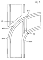
- FIGS. 7 and 8th In the presentation of the FIGS. 7 and 8th can be seen which segments are arranged in which position to the position of the switch in the branching direction (second position of the switch).
- the segments 300A and 302A are in their respective active position, as well as segment 304.
- the segments 300B, 302B and 310 are in their respective active position. Active position is understood to mean that the affected segments are parts of the track. In a corresponding passive position (or: park position) the affected segments are not part of the track.
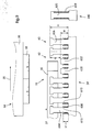
- FIG. 9 shown sectional view through the primary part 34 can see the hubs 60 of magnetizable material, wherein in the region of the switch 18, two hubs 600, 602 compared to the height H of hubs 604, 606 outside the area of the switch 18 a smaller (or: reduced or reduced) Have height H '. This results in a recess 62 of height h, through which the rails 30 (or 32) can pass unhindered.
- the windings 608 can be fixed by lugs 610 arranged on the winding cores 60, the lugs 610 preferably being arranged at the same height (substantially H ") on all winding cores 60.
- the lugs 610 can also be formed by projections on the winding cores 60.
- FIG. 9 also shows the trained as a carriage or carriage 14 secondary part 38, ie the rotor of the drive, which by an air gap 37 spaced from the Primary part 34 is movably arranged.
- at least one permanent magnet 33 (alternatively: a rotor cage of an asynchronous machine) is arranged on the carriage 14 for coupling.
- the permanent magnet 33 may also be provided a magnetizable winding core and an electrically energizable coil.
- the primary part 34 (and in particular the winding cores 60) consist of many layers against each other insulated electrical sheets and form a laminated stator core.
- the propulsion movement of the carriage 14 can be influenced in a customary manner by means not shown control or regulating devices which control the energization of the windings 608 or regulated in the desired manner, ie the carriage 14 may, for. B. accelerated or braked, with constant speed, distance to other cars or be moved in accordance with the register.
- Primaries 340 outside the region of the switch, particularly in paths 20, 22 and 24, may conventionally have windings 609 which utilize substantially the full height of the hubs 620 and thus have an optimized fill factor and produce a larger magnetic flux density in the gap , In this way it can be achieved in an advantageous manner that high winding cores are used with low fill factor only in the area of the switch.
- FIG. 9 illustrated primary part 34 may be part of a switch component, so that the term used in this application "within the range of the switch” can also be understood so that it is meant in the region of the switch component, while the primary part 340 part of a (soft) track component can, so the in This term “outside the area of the switch” can also be understood to mean that it is meant in the area of the track component.
- Turnout unit 70 (front view) shown comprises a linear guide 72 (with rail 73) for a mounting element 74 (alternative designation: base plate), on which the segment 302B of the rail 32 is arranged.
- the segment 302 B can be moved from its active position linearly along the linear guide (in the figure up) in its passive position. This movement is illustrated by the arrow 76.
- the linear adjustment movement takes place substantially perpendicular to the direction of the incoming path 20 and in the plane spanned by the two rails 30, 32 level.
- the segment 302A may be moved from its passive position (in FIG. 10 behind the mounting plate 74, not visible) linearly along a linear guide (in the figure forward, see direction of movement 78) are moved from its passive position to the active position.
- This adjustment movement takes place substantially perpendicular to the direction of the incoming path 20 and perpendicular to the plane spanned by the two rails 30, 32 level.
- segments 300A, 3 are adjusted by means of linear guides 80, 82.
- the segments 304, 310 can be moved by means of linear guides alternately from passive to active positions and back.
- FIG. 11 the point setting unit is shown from the rear (rear view), with segment 300B being seen in its passive position.
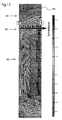
- FIG. 12 1 shows a detail of a simulated winding core 90 and an overlying, separated by an air gap 92 of the winding core 90 (spaced) permanent magnet 94 and the field lines 96 of the magnetic flux density B in this section.
- the gray values used in the figure indicate the magnitude of the magnetic flux density B.
- the numbers 0 and 5 indicate the position in the air gap, as shown in the diagram in FIG. 13 plotted on the abscissa.
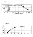
- FIG. 3 shows a diagram in which the magnetic flux density B (in Tesla) is above the position in the air gap 92 (see numbers 0 and 5 in FIG FIG. 12 ) is applied for different free heights of the winding core 90.
- B in Tesla
- free heights of the winding core is to be understood the portion of the winding core, which is not wrapped by a coil. It can be seen clearly that the variable (see various drawn curves), only partially wrapping the winding core has only a small influence on the magnetic flux density B. Further, the magnetic flux density is substantially constant over about 3/5 of the gap area (0 to 3).
- FIG. 14 is a diagram in which the average relative flux density (in Tesla) over the fill factor (in%) is plotted.
Landscapes
- Engineering & Computer Science (AREA)
- Power Engineering (AREA)
- Mechanical Engineering (AREA)
- Physics & Mathematics (AREA)
- Chemical & Material Sciences (AREA)
- Combustion & Propulsion (AREA)
- Electromagnetism (AREA)
- Linear Motors (AREA)
- Feeding Of Articles By Means Other Than Belts Or Rollers (AREA)
- Non-Mechanical Conveyors (AREA)
Applications Claiming Priority (2)
| Application Number | Priority Date | Filing Date | Title |
|---|---|---|---|
| DE2003151619 DE10351619A1 (de) | 2003-11-05 | 2003-11-05 | Transportsystem in einer Bedruckstoff verarbeitenden Maschine |
| DE10351619 | 2003-11-05 |
Publications (2)
| Publication Number | Publication Date |
|---|---|
| EP1529639A1 EP1529639A1 (de) | 2005-05-11 |
| EP1529639B1 true EP1529639B1 (de) | 2012-08-08 |
Family
ID=34428565
Family Applications (1)
| Application Number | Title | Priority Date | Filing Date |
|---|---|---|---|
| EP20040105466 Expired - Lifetime EP1529639B1 (de) | 2003-11-05 | 2004-11-03 | Transportsystem in einer Bedruckstoff verarbeitenden Maschine und Verfahren zur Herstellung eines Primärteils eines elektrischen Linearantriebs |
Country Status (5)
| Country | Link |
|---|---|
| EP (1) | EP1529639B1 (enExample) |
| JP (1) | JP4587285B2 (enExample) |
| CN (1) | CN100503400C (enExample) |
| DE (1) | DE10351619A1 (enExample) |
| RU (1) | RU2004132145A (enExample) |
Cited By (1)
| Publication number | Priority date | Publication date | Assignee | Title |
|---|---|---|---|---|
| DE102013009812A1 (de) | 2012-06-15 | 2013-12-19 | Heidelberger Druckmaschinen Ag | Verfahren und Vorrichtung für das indirekte Bedrucken von Drucksubstraten |
Families Citing this family (6)
| Publication number | Priority date | Publication date | Assignee | Title |
|---|---|---|---|---|
| CN1986219B (zh) | 2005-12-23 | 2011-04-20 | 海德堡印刷机械股份公司 | 修正承印材料侧向位置的方法和装置、输送系统和加工机器 |
| EP2049344B1 (de) | 2006-07-26 | 2015-09-30 | Müller Martini Holding AG | Buchbindemaschine |
| DE102007014876B4 (de) * | 2007-03-26 | 2010-04-08 | Kba-Metronic Aktiengesellschaft | Transportsystem |
| DE102008031734A1 (de) * | 2008-07-04 | 2010-02-04 | Heidelberger Druckmaschinen Ag | Verfahren zum Separieren von wenigstens zwei Brücken eines segmentierten Transportsystems für Bedruckstoffe |
| EP4339140A1 (de) * | 2022-09-14 | 2024-03-20 | Siemens Aktiengesellschaft | Anordnung, weiche, verfahren, computersystem, computerprogrammprodukt |
| US12103402B2 (en) | 2022-09-14 | 2024-10-01 | Rockwell Automation Technologies, Inc. | System and method for controlling direction of a vehicle in an independent cart system |
Family Cites Families (18)
| Publication number | Priority date | Publication date | Assignee | Title |
|---|---|---|---|---|
| JPS596763A (ja) * | 1982-07-02 | 1984-01-13 | Toshiba Corp | 超電導磁気浮上式鉄道用分岐装置 |
| JPS59122601A (ja) * | 1982-12-29 | 1984-07-16 | 株式会社 富士電機総合研究所 | 吸引力形磁気浮上車の軌道分岐装置 |
| DE3338199A1 (de) * | 1983-10-20 | 1985-05-09 | Götz Dipl.-Phys. 8136 Percha Heidelberg | Transporteinrichtung nach art einer foerderbandeinrichtung |
| JPS60204250A (ja) * | 1984-03-26 | 1985-10-15 | Toshiba Corp | 搬送装置 |
| JPS61202505U (enExample) * | 1985-06-05 | 1986-12-19 | ||
| JPS62200666U (enExample) * | 1986-06-11 | 1987-12-21 | ||
| JPS63101241A (ja) * | 1986-10-20 | 1988-05-06 | Hitachi Ltd | 媒体搬送装置 |
| JPS63172439A (ja) * | 1987-01-09 | 1988-07-16 | Mitsubishi Electric Corp | 半導体ウエ−ハ移送装置 |
| JPS6449238A (en) * | 1987-08-19 | 1989-02-23 | Fuji Electric Co Ltd | Transfer equipment |
| NL8902586A (nl) * | 1989-10-19 | 1991-05-16 | Vanderlande Ind Nederland | Transportinrichting. |
| JPH03293222A (ja) * | 1990-04-06 | 1991-12-24 | Fujitsu Ltd | 搬送装置 |
| JP3068287B2 (ja) * | 1991-11-21 | 2000-07-24 | 財団法人鉄道総合技術研究所 | 鉄道の分岐装置 |
| DE4311863C1 (de) * | 1993-04-10 | 1994-08-04 | Robert Ecker | Kurvenbandförderer mit Faltengurt |
| WO1997045267A1 (de) * | 1996-05-29 | 1997-12-04 | Heidelberger Druckmaschinen Aktiengesellschaft | Bogentransportsystem für eine rotationsdruckmaschine |
| DE19621507C1 (de) * | 1996-05-29 | 1997-09-18 | Heidelberger Druckmasch Ag | Bahneinzugsvorrichtung für eine bahnförmiges Material verarbeitende Maschine, insbesondere eine Rollenrotations-Druckmaschine |
| JP4027424B2 (ja) * | 1996-05-29 | 2007-12-26 | ハイデルベルガー ドルツクマシーネン アクチエンゲゼルシヤフト | 輪転印刷機のための枚葉紙搬送機構 |
| US5947361A (en) * | 1996-07-25 | 1999-09-07 | Emo Elektromotorenwerk Kamenz Gmbh | Apparatus for transporting fabrics and web-shaped material with an electric drive device |
| JP2002320373A (ja) * | 2001-04-18 | 2002-10-31 | Hitachi Kiden Kogyo Ltd | リニアモータ |
-
2003
- 2003-11-05 DE DE2003151619 patent/DE10351619A1/de not_active Withdrawn
-
2004
- 2004-10-27 JP JP2004312997A patent/JP4587285B2/ja not_active Expired - Fee Related
- 2004-10-28 CN CNB2004100899860A patent/CN100503400C/zh not_active Expired - Fee Related
- 2004-11-03 EP EP20040105466 patent/EP1529639B1/de not_active Expired - Lifetime
- 2004-11-04 RU RU2004132145/12A patent/RU2004132145A/ru not_active Application Discontinuation
Cited By (1)
| Publication number | Priority date | Publication date | Assignee | Title |
|---|---|---|---|---|
| DE102013009812A1 (de) | 2012-06-15 | 2013-12-19 | Heidelberger Druckmaschinen Ag | Verfahren und Vorrichtung für das indirekte Bedrucken von Drucksubstraten |
Also Published As
| Publication number | Publication date |
|---|---|
| RU2004132145A (ru) | 2006-04-10 |
| JP4587285B2 (ja) | 2010-11-24 |
| DE10351619A1 (de) | 2005-06-09 |
| EP1529639A1 (de) | 2005-05-11 |
| CN1613736A (zh) | 2005-05-11 |
| JP2005139002A (ja) | 2005-06-02 |
| CN100503400C (zh) | 2009-06-24 |
Similar Documents
| Publication | Publication Date | Title |
|---|---|---|
| EP0907515B1 (de) | Bogentransportsystem für eine rotationsdruckmaschine | |
| EP1508441B1 (de) | Rollenrotationsdruckmaschine und Trichteranordnung | |
| DE10141589B4 (de) | Verfahren zum Betreiben einer Bogen verarbeitenden Maschine und Maschine zur Bearbeitung von Bogen | |
| DE102008021317A1 (de) | Vorrichtung zur Korrektur der Position eines Bedruckstoffs in seitlicher Richtung | |
| DE102004033923A1 (de) | Rollenrotationsdruckmaschine | |
| DE102004033920B4 (de) | Druckform einer Druckmaschine und Rollenrotationsdruckmaschine | |
| DE19748870C2 (de) | Wendeeinrichtung mit einem Linearantrieb für eine Bogenrotationsdruckmaschine | |
| EP1590283B1 (de) | Druckmaschine mit wenigstens einem druckwerk, einem falzapparat und wenigstens einer wende- und mischstufe | |
| EP1529639B1 (de) | Transportsystem in einer Bedruckstoff verarbeitenden Maschine und Verfahren zur Herstellung eines Primärteils eines elektrischen Linearantriebs | |
| EP1388516A2 (de) | Schnittregister-Einstellvorrichtung | |
| DD234644A1 (de) | Vorrichtung zur regelung der bahnlage | |
| EP1612044A2 (de) | Rollenrotationsdruckmaschine | |
| DE102004033912A1 (de) | Offsetdruckwerk und Rollenrotationsdruckmaschine | |
| EP1055626B1 (de) | Vorrichtung und Verfahren zum Ablenken von Bedruckstoffbogen | |
| EP1556217B1 (de) | Druckmaschine | |
| DE19924265A1 (de) | Vorrichtung zum Verlangsamen von Exemplaren | |
| EP1110894B1 (de) | Verfahren und Vorrichtung zum Falzen von Materialbogen | |
| DE202007012353U1 (de) | Bogenstanz- und -prägemaschine | |
| DE10262338B4 (de) | Rollenrotationsdruckmaschine mit einer mindestens zweit Drucktürme aufweisenden Sektion | |
| EP1383655A1 (de) | Einziehvorrichtung mit einer magnetisch betätigbaren weiche | |
| DE102004043417A1 (de) | Druckmaschine | |
| DE10111648A1 (de) | Vorrichtung zum Schneiden und Falzen von Signaturen | |
| DE202004021116U1 (de) | Druckmaschinen sowie Druckprodukte |
Legal Events
| Date | Code | Title | Description |
|---|---|---|---|
| PUAI | Public reference made under article 153(3) epc to a published international application that has entered the european phase |
Free format text: ORIGINAL CODE: 0009012 |
|
| AK | Designated contracting states |
Kind code of ref document: A1 Designated state(s): AT BE BG CH CY CZ DE DK EE ES FI FR GB GR HU IE IS IT LI LU MC NL PL PT RO SE SI SK TR |
|
| AX | Request for extension of the european patent |
Extension state: AL HR LT LV MK YU |
|
| 17P | Request for examination filed |
Effective date: 20051111 |
|
| AKX | Designation fees paid |
Designated state(s): AT BE BG CH CY CZ DE DK EE ES FI FR GB GR HU IE IS IT LI LU MC NL PL PT RO SE SI SK TR |
|
| REG | Reference to a national code |
Ref country code: DE Ref legal event code: R079 Ref document number: 502004013674 Country of ref document: DE Free format text: PREVIOUS MAIN CLASS: B41F0013004000 Ipc: H02K0003120000 |
|
| GRAP | Despatch of communication of intention to grant a patent |
Free format text: ORIGINAL CODE: EPIDOSNIGR1 |
|
| RIC1 | Information provided on ipc code assigned before grant |
Ipc: H02K 41/03 20060101ALI20120206BHEP Ipc: H02K 3/18 20060101ALI20120206BHEP Ipc: H02K 3/12 20060101AFI20120206BHEP |
|
| RTI1 | Title (correction) |
Free format text: DEVICE FOR CONVEYING PRINTING MATERIAL IN A MACHINE AND METHOD FOR THE PRODUCTION OF A PRIMARY MEMBER OF AN ELECTRICAL LINEAR MOTOR |
|
| RIN1 | Information on inventor provided before grant (corrected) |
Inventor name: SCHAEFFER, THOMAS, DR. Inventor name: FRANK, HENDRIK Inventor name: BALLANDT, FRANK, DR. Inventor name: BERGER, DIETMAR Inventor name: SCHLEWEIS, IVONNE |
|
| GRAS | Grant fee paid |
Free format text: ORIGINAL CODE: EPIDOSNIGR3 |
|
| GRAA | (expected) grant |
Free format text: ORIGINAL CODE: 0009210 |
|
| AK | Designated contracting states |
Kind code of ref document: B1 Designated state(s): AT BE BG CH CY CZ DE DK EE ES FI FR GB GR HU IE IS IT LI LU MC NL PL PT RO SE SI SK TR |
|
| REG | Reference to a national code |
Ref country code: GB Ref legal event code: FG4D Free format text: NOT ENGLISH Ref country code: DE Ref legal event code: R081 Ref document number: 502004013674 Country of ref document: DE Owner name: HEIDELBERGER DRUCKMASCHINEN AG, DE Free format text: FORMER OWNER: HEIDELBERGER DRUCKMASCHINEN AG, 69115 HEIDELBERG, DE |
|
| REG | Reference to a national code |
Ref country code: CH Ref legal event code: EP Ref country code: AT Ref legal event code: REF Ref document number: 570185 Country of ref document: AT Kind code of ref document: T Effective date: 20120815 |
|
| REG | Reference to a national code |
Ref country code: IE Ref legal event code: FG4D Free format text: LANGUAGE OF EP DOCUMENT: GERMAN |
|
| REG | Reference to a national code |
Ref country code: DE Ref legal event code: R096 Ref document number: 502004013674 Country of ref document: DE Effective date: 20121011 |
|
| REG | Reference to a national code |
Ref country code: NL Ref legal event code: VDEP Effective date: 20120808 |
|
| PG25 | Lapsed in a contracting state [announced via postgrant information from national office to epo] |
Ref country code: CY Free format text: LAPSE BECAUSE OF FAILURE TO SUBMIT A TRANSLATION OF THE DESCRIPTION OR TO PAY THE FEE WITHIN THE PRESCRIBED TIME-LIMIT Effective date: 20120808 Ref country code: IS Free format text: LAPSE BECAUSE OF FAILURE TO SUBMIT A TRANSLATION OF THE DESCRIPTION OR TO PAY THE FEE WITHIN THE PRESCRIBED TIME-LIMIT Effective date: 20121208 Ref country code: FI Free format text: LAPSE BECAUSE OF FAILURE TO SUBMIT A TRANSLATION OF THE DESCRIPTION OR TO PAY THE FEE WITHIN THE PRESCRIBED TIME-LIMIT Effective date: 20120808 |
|
| PG25 | Lapsed in a contracting state [announced via postgrant information from national office to epo] |
Ref country code: PL Free format text: LAPSE BECAUSE OF FAILURE TO SUBMIT A TRANSLATION OF THE DESCRIPTION OR TO PAY THE FEE WITHIN THE PRESCRIBED TIME-LIMIT Effective date: 20120808 Ref country code: SI Free format text: LAPSE BECAUSE OF FAILURE TO SUBMIT A TRANSLATION OF THE DESCRIPTION OR TO PAY THE FEE WITHIN THE PRESCRIBED TIME-LIMIT Effective date: 20120808 Ref country code: GR Free format text: LAPSE BECAUSE OF FAILURE TO SUBMIT A TRANSLATION OF THE DESCRIPTION OR TO PAY THE FEE WITHIN THE PRESCRIBED TIME-LIMIT Effective date: 20121109 Ref country code: SE Free format text: LAPSE BECAUSE OF FAILURE TO SUBMIT A TRANSLATION OF THE DESCRIPTION OR TO PAY THE FEE WITHIN THE PRESCRIBED TIME-LIMIT Effective date: 20120808 Ref country code: PT Free format text: LAPSE BECAUSE OF FAILURE TO SUBMIT A TRANSLATION OF THE DESCRIPTION OR TO PAY THE FEE WITHIN THE PRESCRIBED TIME-LIMIT Effective date: 20121210 |
|
| PG25 | Lapsed in a contracting state [announced via postgrant information from national office to epo] |
Ref country code: NL Free format text: LAPSE BECAUSE OF FAILURE TO SUBMIT A TRANSLATION OF THE DESCRIPTION OR TO PAY THE FEE WITHIN THE PRESCRIBED TIME-LIMIT Effective date: 20120808 |
|
| PGFP | Annual fee paid to national office [announced via postgrant information from national office to epo] |
Ref country code: FR Payment date: 20121214 Year of fee payment: 9 |
|
| PG25 | Lapsed in a contracting state [announced via postgrant information from national office to epo] |
Ref country code: ES Free format text: LAPSE BECAUSE OF FAILURE TO SUBMIT A TRANSLATION OF THE DESCRIPTION OR TO PAY THE FEE WITHIN THE PRESCRIBED TIME-LIMIT Effective date: 20121119 Ref country code: RO Free format text: LAPSE BECAUSE OF FAILURE TO SUBMIT A TRANSLATION OF THE DESCRIPTION OR TO PAY THE FEE WITHIN THE PRESCRIBED TIME-LIMIT Effective date: 20120808 Ref country code: DK Free format text: LAPSE BECAUSE OF FAILURE TO SUBMIT A TRANSLATION OF THE DESCRIPTION OR TO PAY THE FEE WITHIN THE PRESCRIBED TIME-LIMIT Effective date: 20120808 Ref country code: CZ Free format text: LAPSE BECAUSE OF FAILURE TO SUBMIT A TRANSLATION OF THE DESCRIPTION OR TO PAY THE FEE WITHIN THE PRESCRIBED TIME-LIMIT Effective date: 20120808 Ref country code: EE Free format text: LAPSE BECAUSE OF FAILURE TO SUBMIT A TRANSLATION OF THE DESCRIPTION OR TO PAY THE FEE WITHIN THE PRESCRIBED TIME-LIMIT Effective date: 20120808 |
|
| BERE | Be: lapsed |
Owner name: HEIDELBERGER DRUCKMASCHINEN A.G. Effective date: 20121130 |
|
| PG25 | Lapsed in a contracting state [announced via postgrant information from national office to epo] |
Ref country code: SK Free format text: LAPSE BECAUSE OF FAILURE TO SUBMIT A TRANSLATION OF THE DESCRIPTION OR TO PAY THE FEE WITHIN THE PRESCRIBED TIME-LIMIT Effective date: 20120808 Ref country code: IT Free format text: LAPSE BECAUSE OF FAILURE TO SUBMIT A TRANSLATION OF THE DESCRIPTION OR TO PAY THE FEE WITHIN THE PRESCRIBED TIME-LIMIT Effective date: 20120808 |
|
| PLBE | No opposition filed within time limit |
Free format text: ORIGINAL CODE: 0009261 |
|
| STAA | Information on the status of an ep patent application or granted ep patent |
Free format text: STATUS: NO OPPOSITION FILED WITHIN TIME LIMIT |
|
| REG | Reference to a national code |
Ref country code: CH Ref legal event code: PL |
|
| 26N | No opposition filed |
Effective date: 20130510 |
|
| GBPC | Gb: european patent ceased through non-payment of renewal fee |
Effective date: 20121108 |
|
| PG25 | Lapsed in a contracting state [announced via postgrant information from national office to epo] |
Ref country code: BG Free format text: LAPSE BECAUSE OF FAILURE TO SUBMIT A TRANSLATION OF THE DESCRIPTION OR TO PAY THE FEE WITHIN THE PRESCRIBED TIME-LIMIT Effective date: 20121108 Ref country code: CH Free format text: LAPSE BECAUSE OF NON-PAYMENT OF DUE FEES Effective date: 20121130 Ref country code: LI Free format text: LAPSE BECAUSE OF NON-PAYMENT OF DUE FEES Effective date: 20121130 |
|
| REG | Reference to a national code |
Ref country code: IE Ref legal event code: MM4A |
|
| PG25 | Lapsed in a contracting state [announced via postgrant information from national office to epo] |
Ref country code: BE Free format text: LAPSE BECAUSE OF NON-PAYMENT OF DUE FEES Effective date: 20121130 |
|
| REG | Reference to a national code |
Ref country code: DE Ref legal event code: R097 Ref document number: 502004013674 Country of ref document: DE Effective date: 20130510 |
|
| PG25 | Lapsed in a contracting state [announced via postgrant information from national office to epo] |
Ref country code: IE Free format text: LAPSE BECAUSE OF NON-PAYMENT OF DUE FEES Effective date: 20121103 |
|
| PG25 | Lapsed in a contracting state [announced via postgrant information from national office to epo] |
Ref country code: GB Free format text: LAPSE BECAUSE OF NON-PAYMENT OF DUE FEES Effective date: 20121108 |
|
| REG | Reference to a national code |
Ref country code: AT Ref legal event code: MM01 Ref document number: 570185 Country of ref document: AT Kind code of ref document: T Effective date: 20121130 |
|
| PG25 | Lapsed in a contracting state [announced via postgrant information from national office to epo] |
Ref country code: AT Free format text: LAPSE BECAUSE OF NON-PAYMENT OF DUE FEES Effective date: 20121130 |
|
| PG25 | Lapsed in a contracting state [announced via postgrant information from national office to epo] |
Ref country code: TR Free format text: LAPSE BECAUSE OF FAILURE TO SUBMIT A TRANSLATION OF THE DESCRIPTION OR TO PAY THE FEE WITHIN THE PRESCRIBED TIME-LIMIT Effective date: 20120808 Ref country code: MC Free format text: LAPSE BECAUSE OF NON-PAYMENT OF DUE FEES Effective date: 20121130 |
|
| PG25 | Lapsed in a contracting state [announced via postgrant information from national office to epo] |
Ref country code: LU Free format text: LAPSE BECAUSE OF NON-PAYMENT OF DUE FEES Effective date: 20121103 |
|
| PG25 | Lapsed in a contracting state [announced via postgrant information from national office to epo] |
Ref country code: HU Free format text: LAPSE BECAUSE OF FAILURE TO SUBMIT A TRANSLATION OF THE DESCRIPTION OR TO PAY THE FEE WITHIN THE PRESCRIBED TIME-LIMIT Effective date: 20041103 |
|
| REG | Reference to a national code |
Ref country code: FR Ref legal event code: ST Effective date: 20140731 |
|
| PG25 | Lapsed in a contracting state [announced via postgrant information from national office to epo] |
Ref country code: FR Free format text: LAPSE BECAUSE OF NON-PAYMENT OF DUE FEES Effective date: 20131202 |
|
| REG | Reference to a national code |
Ref country code: DE Ref legal event code: R081 Ref document number: 502004013674 Country of ref document: DE Owner name: HEIDELBERGER DRUCKMASCHINEN AG, DE Free format text: FORMER OWNER: HEIDELBERGER DRUCKMASCHINEN AKTIENGESELLSCHAFT, 69115 HEIDELBERG, DE |
|
| PGFP | Annual fee paid to national office [announced via postgrant information from national office to epo] |
Ref country code: DE Payment date: 20181130 Year of fee payment: 15 |
|
| REG | Reference to a national code |
Ref country code: DE Ref legal event code: R119 Ref document number: 502004013674 Country of ref document: DE |
|
| PG25 | Lapsed in a contracting state [announced via postgrant information from national office to epo] |
Ref country code: DE Free format text: LAPSE BECAUSE OF NON-PAYMENT OF DUE FEES Effective date: 20200603 |